EP0179271A2 - Filling arrangement for filling closed liquid heating circuits - Google Patents
Filling arrangement for filling closed liquid heating circuits Download PDFInfo
- Publication number
- EP0179271A2 EP0179271A2 EP85111774A EP85111774A EP0179271A2 EP 0179271 A2 EP0179271 A2 EP 0179271A2 EP 85111774 A EP85111774 A EP 85111774A EP 85111774 A EP85111774 A EP 85111774A EP 0179271 A2 EP0179271 A2 EP 0179271A2
- Authority
- EP
- European Patent Office
- Prior art keywords
- pressure
- valve
- filling device
- filling
- backflow preventer
- Prior art date
- Legal status (The legal status is an assumption and is not a legal conclusion. Google has not performed a legal analysis and makes no representation as to the accuracy of the status listed.)
- Granted
Links
- 238000010438 heat treatment Methods 0.000 title claims abstract description 5
- 239000007788 liquid Substances 0.000 title 1
- 239000003638 chemical reducing agent Substances 0.000 claims abstract description 51
- 238000013459 approach Methods 0.000 claims description 10
- 230000001419 dependent effect Effects 0.000 claims description 2
- 238000007789 sealing Methods 0.000 description 7
- 238000000926 separation method Methods 0.000 description 4
- 238000005429 filling process Methods 0.000 description 3
- XLYOFNOQVPJJNP-UHFFFAOYSA-N water Substances O XLYOFNOQVPJJNP-UHFFFAOYSA-N 0.000 description 3
- 230000007423 decrease Effects 0.000 description 2
- 238000011161 development Methods 0.000 description 2
- 230000018109 developmental process Effects 0.000 description 2
- 238000013022 venting Methods 0.000 description 2
- 241001295925 Gegenes Species 0.000 description 1
- 244000089486 Phragmites australis subsp australis Species 0.000 description 1
- 230000033228 biological regulation Effects 0.000 description 1
- 230000006835 compression Effects 0.000 description 1
- 238000007906 compression Methods 0.000 description 1
- 238000013461 design Methods 0.000 description 1
- 238000006073 displacement reaction Methods 0.000 description 1
- 230000000694 effects Effects 0.000 description 1
- 239000012528 membrane Substances 0.000 description 1
- 238000000034 method Methods 0.000 description 1
- 238000012986 modification Methods 0.000 description 1
- 230000004048 modification Effects 0.000 description 1
- 108090000623 proteins and genes Proteins 0.000 description 1
- 210000002023 somite Anatomy 0.000 description 1
- 238000012546 transfer Methods 0.000 description 1
- 238000009423 ventilation Methods 0.000 description 1
- 238000011179 visual inspection Methods 0.000 description 1
Images
Classifications
-
- F—MECHANICAL ENGINEERING; LIGHTING; HEATING; WEAPONS; BLASTING
- F24—HEATING; RANGES; VENTILATING
- F24D—DOMESTIC- OR SPACE-HEATING SYSTEMS, e.g. CENTRAL HEATING SYSTEMS; DOMESTIC HOT-WATER SUPPLY SYSTEMS; ELEMENTS OR COMPONENTS THEREFOR
- F24D3/00—Hot-water central heating systems
- F24D3/10—Feed-line arrangements, e.g. providing for heat-accumulator tanks, expansion tanks ; Hydraulic components of a central heating system
- F24D3/1083—Filling valves or arrangements for filling
-
- F—MECHANICAL ENGINEERING; LIGHTING; HEATING; WEAPONS; BLASTING
- F24—HEATING; RANGES; VENTILATING
- F24D—DOMESTIC- OR SPACE-HEATING SYSTEMS, e.g. CENTRAL HEATING SYSTEMS; DOMESTIC HOT-WATER SUPPLY SYSTEMS; ELEMENTS OR COMPONENTS THEREFOR
- F24D19/00—Details
- F24D19/10—Arrangement or mounting of control or safety devices
- F24D19/1006—Arrangement or mounting of control or safety devices for water heating systems
- F24D19/1009—Arrangement or mounting of control or safety devices for water heating systems for central heating
- F24D19/1015—Arrangement or mounting of control or safety devices for water heating systems for central heating using a valve or valves
- F24D19/1036—Having differential pressure measurement facilities
-
- F—MECHANICAL ENGINEERING; LIGHTING; HEATING; WEAPONS; BLASTING
- F24—HEATING; RANGES; VENTILATING
- F24D—DOMESTIC- OR SPACE-HEATING SYSTEMS, e.g. CENTRAL HEATING SYSTEMS; DOMESTIC HOT-WATER SUPPLY SYSTEMS; ELEMENTS OR COMPONENTS THEREFOR
- F24D3/00—Hot-water central heating systems
- F24D3/10—Feed-line arrangements, e.g. providing for heat-accumulator tanks, expansion tanks ; Hydraulic components of a central heating system
Definitions
- the invention relates to a filling device for filling a closed system, e.g. a heating system, with a filling medium to a predetermined internal pressure, consisting of a pressure reducer connectable on the inlet side to a supply line and on the outlet side via a backflow preventer to the closed system.
- a filling device for filling a closed system, e.g. a heating system, with a filling medium to a predetermined internal pressure, consisting of a pressure reducer connectable on the inlet side to a supply line and on the outlet side via a backflow preventer to the closed system.
- Pressure reducers of this type for example the filling group type 2128 from the applicant, are used, for example, for filling a closed heating system and are used to fill this system automatically.
- the pressure reducer is set to a predetermined pressure and closes when this pressure is reached, so that the pressure in the closed system cannot exceed a predetermined value.
- the backflow preventer is provided between the outlet side of the pressure reducer and the closed system changes that the filling medium or water from the closed system can be pushed back into the supply line if the inlet pressure of the pressure reducer drops below the internal pressure of the closed system.
- the known filling device is not constantly connected to the closed system according to existing regulations, but only via a hose line to be removed after the filling process.
- This has a disadvantageous effect, particularly in the case of larger systems, because the venting process of such systems takes long times, possibly up to 6 months, and during this venting period, filling medium or water must be constantly topped up in the system so that the required pressure within the closed system is maintained. Repeated refilling operations of this type are tedious, and for this reason attempts have been made to automatically fill the closed system in compliance with the legal provisions by connecting an unpressurized water tank, which is controlled by a float valve, to the closed system via a booster pump becomes.
- a booster pump is relatively complex and also disadvantageous in that a booster pump must be used, although the pressure in the supply line itself would be sufficient to ensure the necessary filling pressure of the closed system.
- the object of the invention is an automatic filling device to create the type mentioned above, which can be connected directly to the supply line and allows the pressure in the supply line to be used to automatically fill the closed system.
- this object is achieved in that a pipe separator is arranged between the pressure reducer and the backflow preventer and a pressure-dependent control arrangement is provided for the pipe separator, by means of which the pipe separator can be set into a closed position at a first pressure which corresponds to the predetermined internal pressure of the filled system is, in which the connection between the pressure reducer and the backflow preventer is interrupted, and at a second pressure, which is lower than the first pressure, can be set to a second position, in which the pressure reducer is connected to the backflow preventer via the pipe separator and the Permitted passage of the filling medium to the backflow preventer.
- the filling device designed according to the invention represents a unitary assembly that uses the pipe separator to establish a connection between the supply line and the closed system.
- This module can always be left in connection with the supply line and the closed system without the risk that the filling medium is pressed back out of the closed system into the supply line.
- the interposition of the pipe separator controlled by the control arrangement brings about a safe separation of the supply line from the closed system, if its predetermined Internal pressure is reached.
- the pipe separator ensures that filling medium is pressed back into the supply line from the filled system if the pressure in the supply line drops below the internal pressure prevailing in the filled system.
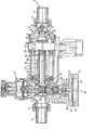
- the figure shows a longitudinal section through the embodiment of the filling device.
- This consists of an essentially conventionally constructed pressure reducer, which is generally designated 1.
- This pressure reducer is set to a pressure which is matched to the predetermined internal pressure or filling pressure of the closed system.
- the structure of the pressure reducer 1 and its function and setting are known and are therefore not described in detail.
- the pressure reducer On the input side, the pressure reducer is provided with a connecting piece 2, to which a connecting piece 4 is fastened by means of a union nut 3, by means of which the pressure reducer 1 can be permanently connected to a supply line, not shown.
- a shoulder 5 is firmly connected to the pressure reducer 1, which continues pipe separator described below.
- a backflow preventer In the free end 6 of the neck 5, a backflow preventer, generally designated 7, is inserted by means of a connecting part 8.
- the backflow preventer 7 carries at the other end on a connecting piece 9 a union nut 10, through which a connector 11 is held, by means of which the entire filling device can be permanently connected as a uniform fitting to the closed system, not shown.
- the backflow preventer 7 contains a spring-loaded closing body which is held by the spring load in a closing system in a seat and blocks the backflow preventer 7 against the neck 5 and thus against the pressure reducer 1.
- the connecting part 8 of the backflow preventer 7 contains a bypass line 13 which bypasses the closing body 12 and opens into an annular chamber 14, in which the internal pressure of the closed system therefore prevails.
- a separation point 15 is installed, which allows a visual inspection of the space between the pipe separator 20 described below and the check valve 7 and in the usual and therefore not particularly described Is trained.
- a leak drain pipe 16 branches off from the attachment 5 and is connected in a conventional manner to an existing disposal line.
- the pressure reducer 1 also carries on one side a not particularly marked setting device of conventional design for setting an off gear pressure, which is matched to the predetermined internal pressure or filling pressure of the closed system. On the opposite side, the pressure reducer 1 carries a control arrangement 40, described in detail below, for controlling the pipe separator 20.
- the approach 5 of the pressure reducer 1 is designed so that it serves as a housing for the pipe separator 20.
- This pipe separator 20 consists of a pipe 21 which is closed on one side and which is inserted in a sealing manner in the attachment 5 on the pressure reducer 1.
- At the closed end of the tube 21 through openings 22 are formed in its side wall, three of which can be seen in the figure.
- An annular piston 23 is displaceable on the tube 21 against the force of a spring 24.
- the head 25 of the annular piston 23 faces the pressure reducer 1; the spring 24 acts on the side of the head 25 facing away from the pressure reducer 1 and is supported on an abutment 26 which is held on the extension 5 in the vicinity of the separation point 15.
- the annular piston 23 also has a recess 27 in its wall and forms an annular gap 28 between the recess 27 and the through openings 22 in the tube 21 which is closed on one side.
- the pipe separator 20 is shown in its closed position in the figure. In this position, the annular piston 23 lies in a sealing manner against the tube 21, which is closed on one side, so that the through openings 22 of the tube 21 are closed.
- the connecting part 8 of the backflow preventer 7 contains on the opposite side of the pipe separator 20 a recess 29 which on the ring-shaped gene piston 23 of the pipe separator 20 is adapted and this in its second or open position.
- the recess 29 is provided with sealing means 30, by means of which the annular piston 23 is sealingly inserted into the recess 29 in the second or open position.
- the control arrangement 40 consists essentially of control valves and a differential pressure transmitter for controlling the control valves; the control arrangement 40 is arranged on the pressure regulator 1 on the side opposite the adjusting device.
- the differential pressure transmitter 41 consists essentially of two chambers 42, 43, which are separated from one another by a movable wall 44 in the form of a membrane.
- the chamber 42 facing away from the pressure reducer 1 is connected to the outlet side of the pressure reducer 1 via a connecting line 45 shown in broken lines.
- the chamber 43 is connected to the ring channel 14 in the connecting part 8 of the check valve 7 via a connecting line 46 shown in broken lines.
- the differential pressure sensor 41 is fastened in a sealing manner to a further extension 48 of the pressure reducer 1 by means of a union nut 47.
- the movable wall 44 carries a plate 49, to which a control rod 50 is fastened, which extends sealingly into the interior of the further extension 48 through a sealing body 51.
- a valve seat body 52 is formed in the interior of the pressure reducer 1 on the outlet side thereof in the further extension 48.
- On the valve seat body 52 is located on the side facing away from the pressure difference transmitter 41 a valve seat 53 of a control valve with a spring-loaded valve body 54.
- the valve body 54 is closed by a compression spring which is supported on an opposite part of the pressure reducer 1, in the exemplary embodiment on its single-seat valve held at its valve seat 53.
- the valve body 56 is under the action of a tension spring which is arranged on the valve seat body 52 and the valve body 56 in a closed contact with its valve seat 55 holds.
- An axial bore 57 extends through the valve seat body 52, from which a control line 58 branches off between the valve seats 53 and 55, which connects the axial bore 57 and an annular space of the extension 5 and on a side opposite in the head 25 of the annular piston 23 of the pipe separator 20 opens into the annular space 60.
- a relief line 59 extends from the further extension 48, which extends essentially parallel to the control line 58 and extension 5 and extends to the leakage drain pipe 16.
- the control rod 50 of the differential pressure sensor 41 extends sealingly but slidably through the valve body 56 and the valve seat 55 of the relief valve and through the axial bore 57 of the valve seat body 52 and carries at its free end a control body 61 which cooperates with the valve body 54 of the control valve.
- filling medium can pass through the pressure reducer 1 and the tube 21 closed on one side and its through openings 22 into the interior of the annular piston 23 and from there through the recess 29 in the connecting part 8 of the check valve 7 while adjusting its closing body 12 into the closed system flow.
- the filling process continues until pressure equalization between the outlet side of the pressure reducer 1 and the internal pressure of the closed system is established.
- the valve body 56 of the relief valve in which the control rod 50 can be displaceably moved in a sealing manner, remains in the position shown, that is to say in closed contact with the valve seat 55 of the relief valve.
- the filling medium can then flow through the axial bore 57 and the valve seat 55 of the relief valve on the valve seat body 52 into the relief line 59, and the spring 24 brings about the resetting of the annular piston 23.
- the valve body 56 After resetting the annular piston 23 and pressure compensation in the control line 58, the valve body 56 the relief valve is brought back into its closing system on its valve seat 55, so that the filling device again assumes the closed position shown in the figure.
- the pipe separator 20 can under certain circumstances also form a part which is separate from the pressure reducer 1 and which is connected to the outlet side of the pressure reducer 1 using conventional connecting means.
- the chamber 43 of the differential pressure sensor 41 can also be connected in any other conceivable way, that the internal pressure or filling pressure prevailing in the closed system is present in this chamber.
- the relief line 59 can also be routed separately from the attachment 5 to the leak drain pipe 16.
- the arrangement of the different lugs and connecting pieces is arbitrary and does not need to be opposite one another in a crosswise manner as in the exemplary embodiment shown.
Landscapes
- Engineering & Computer Science (AREA)
- General Engineering & Computer Science (AREA)
- Chemical & Material Sciences (AREA)
- Thermal Sciences (AREA)
- Combustion & Propulsion (AREA)
- Mechanical Engineering (AREA)
- Physics & Mathematics (AREA)
- Filling Or Discharging Of Gas Storage Vessels (AREA)
- Safety Valves (AREA)
- Packaging Of Special Articles (AREA)
- Resistance Heating (AREA)
- Instantaneous Water Boilers, Portable Hot-Water Supply Apparatuses, And Control Of Portable Hot-Water Supply Apparatuses (AREA)
- Thermally Insulated Containers For Foods (AREA)
- Basic Packing Technique (AREA)
Abstract
Die Fülleinrichtung besteht aus einem Druckminderer, der eingangsseitig an eine Versorgungsleitung und ausgangsseitig über einen Rückflußverhinderer (7) an eine geschlossene Anlage, z.B: eine Heizungsanlage, anschließbar ist. Zwischen dem Rückflußverhinderer (7) und dem Ausgang des Druckminderers (1) ist ein gesteuerter Rohrtrenner (20) vorgesehen. Eine Steueranordnung (40) aus einem Differenzdruckgeber (41) enthält eine bewegliche Wand (44), die auf einer Seite mit dem Ausgangsdruck des Druckminderers (1) und auf der anderen Seite mit dem Innendruck der geschlossenen Anlage beaufschlagt wird. Mit der beweglichen Wand (44) ist ein federbelasteter Ventilkörper (54) eines Steuerventils gekoppelt, das eine Steuerlei. tung (58) beherrscht und im geöffneten Zustand den Rohr. trenner (20) unter dem Ausgangsdruck des Druckminderers (1) öffnet, so daß Füllmedium durch den Druckminderer (1) hindurch in die geschlossene Anlage übertreten kann. Bei Druckgleichheit bzw. Erreichen des vorgegebenen Fülldrucks wird das Steuerventil geschlossen und der Rohrtrenner (20) mittels eines Entlastungsventils entlastet und in die Schließstellung zurückgeführt.
Description
Die Erfindung betrifft eine Fülleinrichtung zur Füllung einer geschlossenen Anlage, z.B. einer Heizungsanlage, mit einem Füllmedium auf einen vorbestimmten Innendruck, bestehend aus einem eingangsseitig an eine Versorgungsleitung und ausgangsseitig über einen Rückflußverhinderer an die geschlossene Anlage anschließbaren Druckminderer.The invention relates to a filling device for filling a closed system, e.g. a heating system, with a filling medium to a predetermined internal pressure, consisting of a pressure reducer connectable on the inlet side to a supply line and on the outlet side via a backflow preventer to the closed system.
Druckminderer dieser Art, z.B. die Füllgruppe Typ 2128 der Anmelderin, werden beispielsweise zur Füllung an eine geschlossene Heizungsanlage verwendet und dienen dazu, diese Anlage automatisch zu befüllen. Der Druckminderer wird auf einen vorbestimmten Druck eingestellt und schließt bei Erreichen dieses Druckes, so daß der Druck in der geschlossenen Anlage einen so vorgegebenen Wert nicht überschreiten kann. Der Rückflußverhinderer ist zwischen der Ausgangsseite des Druckminderers und der geschlossenen Anlage vorgesehen und verhindert, daß das Füllmedium bzw. Wasser aus der geschlossenen Anlage heraus in die Versorgungsleitung zurückgedrückt werden kann, falls der Eingangsdruck des Druckminderers unter den Innendruck der geschlossenen Anlage abfällt.Pressure reducers of this type, for example the filling group type 2128 from the applicant, are used, for example, for filling a closed heating system and are used to fill this system automatically. The pressure reducer is set to a predetermined pressure and closes when this pressure is reached, so that the pressure in the closed system cannot exceed a predetermined value. The backflow preventer is provided between the outlet side of the pressure reducer and the closed system changes that the filling medium or water from the closed system can be pushed back into the supply line if the inlet pressure of the pressure reducer drops below the internal pressure of the closed system.
Die bekannte Fülleinrichtung wird nach bestehenden Vorschriften nicht ständig, sondern nur über eine nach Beendigung des Füllvorgangs abzunehmende Schlauchleitung an die geschlossene Anlage angeschlossen. Dies wirkt sich besonders bei ausgedehnteren Anlagen nachteilhaft aus, weil der Entlüftungsvorgang solcher Anlagen lange Zeiten, unter Umständen bis zu 6 Monaten, benötigt und während dieser Entlüftungsperiode ständig Füllmedium bzw. Wasser in die Anlage nachgefüllt werden muß, damit der erforderliche Druck innerhalb der geschlossenen Anlage aufrechterhalten bleibt. Solche wiederholt durchzuführenden Nachfüllvorgänge sind mühsam, und aus diesem Grunde hat man versucht, unter Einhaltung der gesetzlichen Bestimmungen eine selbsttätige Füllung der geschlossenen Anlage dadurch zu erreichen, daß ein druckloser Wasserbehälter, der über ein Schwimmerventil gesteuert wird, über eine Druckerhöhungspumpe mit der geschlossenen Anlage verbunden wird. Jedoch ist eine solche Nachfülleinrichtung relativ aufwendig und auch dadurch nachteilhaft, daß eine Druckerhöhungspumpe eingesetzt werden muß, obwohl der Druck in der Versorgungsleitung an sich völlig ausreichen würde, um den notwendigen Fülldruck der geschlossenen Anlage zu gewährleisten.The known filling device is not constantly connected to the closed system according to existing regulations, but only via a hose line to be removed after the filling process. This has a disadvantageous effect, particularly in the case of larger systems, because the venting process of such systems takes long times, possibly up to 6 months, and during this venting period, filling medium or water must be constantly topped up in the system so that the required pressure within the closed system is maintained. Repeated refilling operations of this type are tedious, and for this reason attempts have been made to automatically fill the closed system in compliance with the legal provisions by connecting an unpressurized water tank, which is controlled by a float valve, to the closed system via a booster pump becomes. However, such a refill is relatively complex and also disadvantageous in that a booster pump must be used, although the pressure in the supply line itself would be sufficient to ensure the necessary filling pressure of the closed system.
Dementsprechend besteht die Aufgabe der Erfindung darin, eine selbsttätige Fülleinrichtung der eingangs genannten Art zu schaffen, die direkt an die Versorgungsleitung anschließbar ist und die Ausnutzung des in der Versorgungsleitung herrschenden Druckes zum selbsttätigen Befüllen der geschlossenen Anlage gestattet.Accordingly, the object of the invention is an automatic filling device to create the type mentioned above, which can be connected directly to the supply line and allows the pressure in the supply line to be used to automatically fill the closed system.
Erfindungsgemäß wird diese Aufgabe dadurch gelöst, daß zwischen dem Druckminderer und dem Rückflußverhinderer ein Rohrtrenner angeordnet ist und eine druckabhängige Steueranordnung für den Rohrtrenner vorgesehen ist, mittels derer der Rohrtrenner bei einem ersten Druck, der dem vorbestimmten Innendruck der gefüllten Anlage entspricht, in eine Schließstellung einstellbar ist, in der die Verbindung zwischen dem Druckminderer und dem Rückflußverhinderer unterbrochen ist, und bei einem zweiten Druck, der niedriger als der erste Druck ist, in eine zweite Stellung einstellbar ist, in der der Druckminderer über den Rohrtrenner mit dem Rückflußverhinderer verbunden ist und den Durchtritt des Füllmediums zum Rückflußverhinderer gestattet.According to the invention, this object is achieved in that a pipe separator is arranged between the pressure reducer and the backflow preventer and a pressure-dependent control arrangement is provided for the pipe separator, by means of which the pipe separator can be set into a closed position at a first pressure which corresponds to the predetermined internal pressure of the filled system is, in which the connection between the pressure reducer and the backflow preventer is interrupted, and at a second pressure, which is lower than the first pressure, can be set to a second position, in which the pressure reducer is connected to the backflow preventer via the pipe separator and the Permitted passage of the filling medium to the backflow preventer.
Die erfindungsgemäß ausgebildete Fülleinrichtung stellt eine einheitliche Baugruppe dar, die mittels des Rohrtrenners eine Verbindung zwischen der Versorgungsleitung und der geschlossenen Anlage herstellt. Diese Baugruppe kann ständig in Verbindung mit der Versorgungsleitung und der geschlossenen Anlage belassen bleiben, ohne daß die Gefahr besteht, daß das Füllmedium aus der geschlossenen Anlage in die Versorgungsleitung zurückgedrückt wird. Die Zwischenschaltung des von der Steueranordnung gesteuerten Rohrtrenners bewirkt eine sichere Abtrennung der Versorgungsleitung von der geschlossenen Anlage, wenn deren vorbestimmter Innendruck erreicht ist. Durch den Rohrtrenner wird zusätzlich zu dem Rückflußverhinderer eine Sicherheit dagegen geschaffen, daß aus der gefüllten Anlage Füllmedium in die Versorgungsleitung zurückgedrückt wird, falls der Druck in der Versorgungsleitung unter den in der gefüllten Anlage herrschenden Innendruck absinkt.The filling device designed according to the invention represents a unitary assembly that uses the pipe separator to establish a connection between the supply line and the closed system. This module can always be left in connection with the supply line and the closed system without the risk that the filling medium is pressed back out of the closed system into the supply line. The interposition of the pipe separator controlled by the control arrangement brings about a safe separation of the supply line from the closed system, if its predetermined Internal pressure is reached. In addition to the backflow preventer, the pipe separator ensures that filling medium is pressed back into the supply line from the filled system if the pressure in the supply line drops below the internal pressure prevailing in the filled system.
Vorteilhafte Ausbildungen und Weiterbildungen der Fülleinrichtung nach der Erfindung sind in den Unteransprüchen gekennzeichnet.Advantageous developments and developments of the filling device according to the invention are characterized in the subclaims.
Ein Ausführungsbeispiel der erfindungsgemäßen Fülleinrichtung ist in der Abbildung dargestellt und wird nachfolgend anhand der Bezugszeichen im einzelnen erläutert und beschrieben.An embodiment of the filling device according to the invention is shown in the figure and is explained and described in detail below with reference to the reference numerals.
Die Abbildung zeigt einen Längsschnitt durch das Ausführungsbeispiel der Fülleinrichtung. Diese besteht aus einem im wesentlichen konventionell aufgebauten Druckminderer , der allgemein mit 1 bezeichnet ist. Dieser Druckminderer ist auf einen Druck eingestellt, der auf den vorbestimmten Innendruck oder Fülldruck der geschlossenen Anlage abgestimmt ist. Der Aufbau des Druckminderers 1 und dessen Funktion und Einstellung sind bekannt und werden daher nicht im einzelnen beschrieben. An der Eingangsseite ist der Druckminderer mit einem Anschlußstutzen 2 versehen, an dem mittels einer Überwurfmutter 3 ein Anschlußstück 4 befestigt ist, mittels dessen der Druckminderer 1 bleibend an eine nicht dargestellte Versorgungsleitung angeschlossen werden kann. An der gegenüberliegenden Ausgangsseite des Druckminderers 1 ist ein Ansatz 5 fest mit dem Druckminderer 1 verbunden, der den weiter unten beschriebenen Rohrtrenner aufnimmt. In das freie Ende 6 des Ansatzes 5 ist ein allgemein mit 7 bezeichneter Rückflußverhinderer mittels eines Anschlußteils 8 eingesetzt. Der Rückflußverhinderer 7 trägt am anderen Ende an einem Anschlußstutzen 9 eine Überwurfmutter 10, durch die ein Anschlußstück 11 gehaltert wird, mittels dessen die gesamte Fülleinrichtung als einheitliche Armatur bleibend an die nicht dargestellte geschlossene Anlage angeschlossen werden kann. Der Rückflußverhinderer 7 enthält einen federbelasteten Schließkörper der durch die Federbelastung in schließender Anlage an einem Sitz gehalten wird und den Rückflußverhinderer 7 gegen den Ansatz 5 und damit gegen den Druckminderer 1 absperrt. Das Anschlußteil 8 des Rückflußverhinderers 7 enthält eine Umgehungsleitung 13, die den Schließkörper 12 umgeht und in eine Ringkammer 14 mündet, in der somit der Innendruck der geschlossenen Anlage herrscht.The figure shows a longitudinal section through the embodiment of the filling device. This consists of an essentially conventionally constructed pressure reducer, which is generally designated 1. This pressure reducer is set to a pressure which is matched to the predetermined internal pressure or filling pressure of the closed system. The structure of the pressure reducer 1 and its function and setting are known and are therefore not described in detail. On the input side, the pressure reducer is provided with a connecting piece 2, to which a connecting piece 4 is fastened by means of a
In den Ansatz 5 ist von der geschlossenen Anlage her gesehen vor dem Abschlußteil 8 des Rückflußverhinderers 7 eine Trennstelle 15 eingebaut, die eine visuelle Überprüfung des Zwischenraums zwischen dem weiter unten beschriebenen Rohrtrenner 20 und dem Rückflußverhinderer 7 ermöglicht und in üblicher und daher in nicht besonders beschriebener Weise ausgebildet ist. Im Bereich der Trennstelle 15 zweigt von dem Ansatz 5 ein Leckabflußrohr 16 ab, das in üblicher Weise an eine vorhandene Entsorgungsleitung angeschlossen ist.In the approach 5 is seen from the closed system in front of the end part 8 of the check valve 7, a
Der Druckminderer 1 trägt weiterhin an einer Seite eine nicht besonders gekennzeichnete Einstellvorrichtung üblicher Bauart zur Einstellung eines Ausgangsdrucks, der auf den vorbestimmten Innendruck oder Fülldruck der geschlossenen Anlage abgestimmt ist. An der gegenüberliegenden Seite trägt der Druckminderer 1 eine weiter unten im einzelnen beschriebene Steueranordnung 40 zur Steuerung des Rohrtrenners 20.The pressure reducer 1 also carries on one side a not particularly marked setting device of conventional design for setting an off gear pressure, which is matched to the predetermined internal pressure or filling pressure of the closed system. On the opposite side, the pressure reducer 1 carries a
Der Ansatz 5 des Druckminderers 1 ist so ausgebildet, daß er als Gehäuse für den Rohrtrenner 20 dient..Dieser Rohrtrenner 20 besteht aus einem einseitig geschlossenen Rohr 21, das an dem Druckminderer 1 abdichtend in den Ansatz 5 eingesetzt ist. Am geschlossenen Ende des Rohres 21 sind in dessen Seitenwand Durchgangsöffnungen 22 ausgebildet, von denen drei in der Abbildung erkennbar sind. Auf dem Rohr 21 ist ein ringförmiger Kolben 23 gegen die Kraft einer Feder 24 verschiebbar. Der Kopf 25 des ringförmigen Kolbens 23 ist dem Druckminderer 1 zugekehrt; die Feder 24 wirkt auf die dem Druckminderer 1 abgekehrte Seite des Kopfes 25 und stützt sich an einem Widerlager 26 ab, das in der Nähe der Trennstelle 15 an dem Ansatz 5 gehaltert ist. Der ringförmige Kolben 23 weist weiter in seiner Wandung eine Ausnehmung 27 auf und bildet zwischen der Ausnehmung 27 und den Durchgangsöffnungen 22 in dem einseitig geschlossenen Rohr 21 einen Ringspalt 28.The approach 5 of the pressure reducer 1 is designed so that it serves as a housing for the
Der Rohrtrenner 20 ist in der Abbildung in seiner Schließstellung dargestellt. In dieser Stellung liegt der ringförmige Kolben 23 dem einseitig geschlossenen Rohr 21 abdichtend an, so daß die Durchgangsöffnungen 22 des Rohres 21 geschlossen sind. Das Anschlußteil 8 des Rückflußverhinderers 7 enthält an der dem Rohrtrenner 20 gegenüberliegenden Seite eine Ausnehmung 29, die an den ringförmigen Kolben 23 des Rohrtrenners 20 angepaßt ist und diesen in dessen zweiter oder geöffneter Stellung aufnimmt. Die Ausnehmung 29 ist mit Dichtmitteln 30 versehen, mittels derer der ringförmige Kolben 23 in der zweiten oder geöffneten Stellung abdichtend in die Ausnehmung 29 eingeführt ist.The
Die Steueranordnung 40 besteht im wesentlichen aus Steuerventilen und einem Differenzdruckgeber zur Steuerung der Steuerventile; die Steueranordnung 40 ist an der der Einstellvorrichtung gegenüberliegenden Seite an dem Druckminderer 1 angeordnet.The
Der Differenzdruckgeber 41 besteht im wesentlichen aus zwei Kammern 42,43, die durch eine bewegliche Wand 44 in Gestalt einer Membran voneinander getrennt sind. Die dem Druckminderer 1 abgekehrte Kammer 42 ist über eine gestrichelt gezeichnete Verbindungsleitung 45 an die Ausgangsseite des Druckminderers 1 angeschlossen. Die Kammer 43 ist über eine gestrichelt gezeichnete Verbindungsleitung 46 an den Ringkanal 14 im Anschlußteil 8 des Rückflußverhinderers 7 angeschlossen. Der Differenzdruckgeber 41 ist durch eine Überwurfmutter 47 an einem weiteren Ansatz 48 des Druckminderers 1 abdichtend befestigt.The differential pressure transmitter 41 consists essentially of two
Die bewegliche Wand 44 trägt einen Teller 49, an dem eine Steuerstange 50 befestigt ist, die durch einen Dichtkörper 51 abdichtend in das Innere des weiteren Ansatzes 48 verläuft.The
Im Inneren des Druckminderers 1 ist an dessen Ausgangsseite in dem weiteren Ansatz 48 ein Ventilsitzkörper 52 ausgebildet. An dem Ventilsitzkörper 52 befindet sich an der dem Druckdifferenzgeber 41 abgekehrten Seite ein Ventilsitz 53 eines Steuerventils mit einem federbelasteten Ventilkörper 54. Der Ventilkörper 54 wird durch eine Druckfeder, die sich an einem gegenüberliegenden Teil des Druckminderers 1, im Ausführungsbeispiel an dessen Einsitzventil, abstützt, in schließender Anlage an seinem Ventilsitz 53 gehalten. An der dem Differenzdruckgeber 41 zugekehrten Seite des Ventilsitzkörpers 52 befindet sich ein Ventilsitz 55 eines Entlastungsventils mit einem federbelasteten Ventilkörper 56. Der Ventilkörper 56 steht unter Wirkung einer Zugfeder, die an dem Ventilsitzkörper 52 angeordnet ist und den Ventilkörper 56 in schließender Anlage an seinem Ventilsitz 55 hält. Durch den Ventilsitzkörper 52 hindurch erstreckt sich eine Axialbohrung 57, von der zwischen den Ventilsitzen 53 und 55 eine Steuerleitung 58 abzweigt, die die Axialbohrung 57 und einen Ringraum des Ansatzes 5 verbindet und an einer im Kopf 25 des ringförmigen Kolbens 23 des Rohrtrenners 20 gegenüberliegenden Seite in den Ringraum 60 einmündet. Auf der Höhe des Ventilsitzes 55 des Entlastungsventils erstreckt sich aus dem weiteren Ansatz 48 eine Entlastungsleitung 59, die im wesentlichen parallel zur Steuerleitung 58 und zum Ansatz 5 verläuft und sich zum Leckabflußrohr 16 hin erstreckt.A
Die Steuerstange 50 des Differenzdruckgebers 41 erstreckt sich abdichtend, aber gleitbeweglich durch den Ventilkörper 56 und den Ventilsitz 55 des Entlastungsventils und durch die Axialbohrung 57 des Ventilsitzkörpers 52 hindurch und trägt an ihrem freien Ende einen Steuerkörper 61, der mit dem Ventilkörper 54 des Steuerventils zusammenwirkt.The
Die vorstehend beschriebene Fülleinrichtung arbeitet wie folgt:
- In der Abbildung sind die Fülleinrichtung und der
Rohrtrenner 20 in ihrer Schließstellung dargestellt. Dementsprechend ist der Rückflußverhinderer 7 durch denSchließkörper 12 gegen den Ansatz 5 bzw. das Druckmindererventil 1 geschlossen. Eventuell amSchließkörper 12 austretendes Füllmedium wird durch dasLeckabflußrohr 16 abgeleitet. Derringförmige Kolben 23 ist unter der Wirkung derFeder 24 in die zurückgezogene Stellung eingebracht, in der er dieDurchgangsöffnungen 22 des einseitig geschlossenen Rohres 21 imRohrtrenner 20 verschließt. Der Innendruck oder Fülldruck der geschlossenen Anlage ist dem Ausgangsdruck des Druckminderers 1 gleich, und daher sind auch die in denKammern 42 und 43 des Differenzdruckgebers 41 herrschenden Drücke gleich. DieSteuerstange 51 befindet sich somit in ihrer zurückgezogenen Stellung und derVentilkörper 54 des Steuerventils an der Ausgangsseite des Druckminderers 1 liegt dem Ventilsitz 53 schließend an. Die Steuerleitung 58 und der Innenraum des Ansatzes 5 sind drucklos, so daß auch der Ventilkörper 56 des Entlastungsventils dessenVentilsitz 55 schließend anliegt.
- The figure shows the filling device and the
pipe separator 20 in their closed position. Accordingly, the backflow preventer 7 is closed by theclosing body 12 against the attachment 5 or the pressure reducing valve 1. Any filling medium escaping from the closingbody 12 is drained off through theleakage drain pipe 16. Theannular piston 23 is brought under the action of thespring 24 into the retracted position in which it closes the throughopenings 22 of the tube 21 closed on one side in thetube separator 20. The internal pressure or filling pressure of the closed system is the same as the outlet pressure of the pressure reducer 1, and therefore the pressures prevailing in thechambers control rod 51 is thus in its retracted position and thevalve body 54 of the control valve on the output side of the pressure reducer 1 is in contact with thevalve seat 53. The control line 58 and the interior of the extension 5 are depressurized, so that the valve body 56 of the relief valve, thevalve seat 55 of which is in close contact.
Wenn aus irgendwelchen Gründen, z.B. infolge einer Entlüftung, der Druck des Füllmediums in der geschlossenen Anlage abnimmt, tritt diese Druckabnahme über die Umgehungsleitung 13 und die Ringkammer 14 sowie die Verbindungsleitung 46 auch in der Kammer 43 des Differenzdruckgebers 41 auf. Infolgedessen verschieben sich die mit der beweglichen Wand 44 gekoppelte Steuerstange 50, so daß der Ventilkörper 54 des Steuerventils von seinem Sitz 53 abgehoben wird. Von der Ausgangsseite des Druckmindererventils 1 tritt daher unter Fülldruck stehendes Füllmedium in die Steuerleitung 58 ein und Ubt einen Druck auf den Kopf 25 des ringförmigen Kolbens 23 aus. Wenn dieser Druck die Kraft der Feder 24 überwindet, wird der ringförmige Kolben 23 in die Ausnehmung 29 des Anschlußteils 8 des Rückflußverhinderers 7 verschoben. Durch diese Verschiebung kann Füllmedium durch den Druckminderer 1 und das einseitig geschlossene Rohr 21 und dessen Durchgangsöffnungen 22 hindurch in den Innenraum des ringförmigen Kolbens 23 übertreten und von da durch die Ausnehmung 29 im Anschlußteil 8 des RUckflußverhinderers 7 unter Verstellung dessen Schließkörpers 12 in die geschlossene Anlage fließen. Der Füllvorgang dauert an bis Druckausgleich zwischen der Ausgangsseite des Druckminderers 1 und dem Innendruck der geschlossenen Anlage hergestellt ist. Während des Füllvorgangs bleibt der Ventilkörper 56 des Entlastungsventils, in dem die Steuerstange 50 abdichtend gleitbeweglich verschiebbar ist, in der dargestellten Stellung, d.h. in schließender Anlage an dem Ventilsitz 55 des Entlastungsventils.If, for any reason, for example due to ventilation, the pressure of the filling medium in the closed system decreases, this decrease in pressure occurs via the
Bei Eintritt des Druckausgleichs schließt der Schließkörper 12 des Rückflußverhinderers 7; weiterhin besteht Druckgleichheit in den beiden Kammern 42,43 des Differenzdruckgebers 41, so daß die Steuerstange 50 mit dem Steuerkörper 61 zurückgezogen und das Steuerventil durch Anlage des federbelasteten Ventilkörpers 54 an den Ventilsitz 53 geschlossen wird. Der federbelastete Ventilkörper 56 des Entlastungsventils wird unter der Wir kung des Ausgangsdrucks des Druckminderers 1 in der Steuerleitung 58 und dem Ringraum 60 im Ansatz 5 von seinem Ventilsitz 55 gegen die Kraft seiner Zugfeder abgehoben und auf der Steuerstange 50 bis zur Anlage an die dem Ventilsitzkörper 52 zugekehrte Stirnfläche des Dichtkörpers 51 verschoben. Das FUllmedium kann dann durch die Axialbohrung 57 und den Ventilsitz 55 des Entlastungsventils am Ventilsitzkörper 52 in die Entlastungsleitung 59 abströmen und die Feder 24 bewirkt die Rückstellung des ringförmigen Kolbens 23. Nach Rückstellung des ringförmigen Kolbens 23 und Druckausgleich in der Steuerleitung 58 wird der Ventilkörper 56 des Entlastungsventils wieder in schließende Anlage an seinen Ventilsitz 55 gebracht, so daß die Fülleinrichtung wieder die in der Abbildung dargestellte Schließstellung einnimmt. In dieser Schließstellung ist es ausgeschlossen, daß ein Druckabfall in der an das Anschlußstück 4 angeschlossenen Versorgungsleitung einen Übertritt von Füllmedium durch den Rückflußverhinderer 7 in die Versorgungsleitung bewirkt, da der Rohrtrenner 20 den Druckminderer 1 wirksam gegen aus dem Rückflußverhinderer 7 austretendes Füllmedium abschließt und andererseits gegebenenfalls austretendes Füllmedium durch das Leckabflußrohr 16 abgeleitet wird.When pressure equalization occurs, the closing
Es sind verschiedene Abwandlungen von dem dargestellten Ausführungsbeispiel möglich. So kann der Rohrtrenner 20 unter Umständen auch ein von dem Druckminderer 1 getrenntes Teil bilden, das mit konventionellen Verbindungsmitteln an die Ausgangsseite des Druckminderers 1 angeschlossen ist. Auch kann die Kammer 43 des Differenzdruckgebers 41 in jeder anderen denkbaren Weise so verbunden werden, daß in dieser Kammer der in der geschlossenen Anlage jeweils herrschende Innendruck oder Fülldruck anliegt. Die Entlastungsleitung 59 kann auch getrennt von dem Ansatz 5 zum Leckabflußrohr 16 geführt sein. Schließlich ist die Anordnung der verschiedenen Ansätze und Anschlußstutzen beliebig und braucht nicht kreuzweise gegenüberliegend zu sein wie in dem dargestellten Ausführungsbeispiel.Various modifications of the illustrated embodiment are possible. Thus, the
Claims (16)
dadurch gekennzeichnet, daß zwischen dem Druckminderer (1) und dem Rückflußverhinderer (7) ein Rohrtrenner (20) angeordnet ist und eine druckabhängige Steueranordnung (40) für den Rohrtrenner (20) vorgesehen ist, mittels derer der Rohrtrenner (20) bei einem ersten Druck, der dem vorbestimmten Fülldruck der gefüllten Anlage entspricht, in eine Schließstellung einstellbar ist, in der die Verbindung zwischen dem Druckminderer (1) und dem Rückflußverhinderer (3) unterbrochen ist, und bei einem zweiten Druck, der niedriger als der erste Druck ist, in eine zweite Stellung einstellbar ist, in der der Druckminderer (1) über den Rohrtrenner (20) mit dem Rückflußverhinderer (7) verbunden ist und den Durchtritt zum Rückflußverhinderer (7) gestattet.1. Filling device for filling a closed system, for example a heating system, with a filling medium to a predetermined filling pressure, consisting of a pressure reducer that can be connected to the supply line on the input side and to the system on the output side via a backflow preventer,
characterized in that a pipe separator (20) is arranged between the pressure reducer (1) and the backflow preventer (7) and a pressure-dependent control arrangement (40) for the pipe separator (20) is provided, by means of which the pipe separator (20) at a first pressure , which corresponds to the predetermined filling pressure of the filled system, is adjustable into a closed position in which the connection between the pressure reducer (1) and the backflow preventer (3) is interrupted, and at a second pressure which is lower than the first pressure, in a second position can be set, in which the pressure reducer (1) is connected to the backflow preventer (7) via the pipe separator (20) and allows passage to the backflow preventer (7).
Priority Applications (1)
| Application Number | Priority Date | Filing Date | Title |
|---|---|---|---|
| AT85111774T ATE51955T1 (en) | 1984-09-25 | 1985-09-18 | FILLING DEVICE FOR FILLING CLOSED PLANTS. |
Applications Claiming Priority (2)
| Application Number | Priority Date | Filing Date | Title |
|---|---|---|---|
| DE19843435127 DE3435127A1 (en) | 1984-09-25 | 1984-09-25 | FILLING DEVICE FOR FILLING CLOSED SYSTEMS |
| DE3435127 | 1984-09-25 |
Publications (3)
| Publication Number | Publication Date |
|---|---|
| EP0179271A2 true EP0179271A2 (en) | 1986-04-30 |
| EP0179271A3 EP0179271A3 (en) | 1988-01-07 |
| EP0179271B1 EP0179271B1 (en) | 1990-04-11 |
Family
ID=6246291
Family Applications (1)
| Application Number | Title | Priority Date | Filing Date |
|---|---|---|---|
| EP85111774A Expired - Lifetime EP0179271B1 (en) | 1984-09-25 | 1985-09-18 | Filling arrangement for filling closed liquid heating circuits |
Country Status (3)
| Country | Link |
|---|---|
| EP (1) | EP0179271B1 (en) |
| AT (1) | ATE51955T1 (en) |
| DE (2) | DE3435127A1 (en) |
Cited By (5)
| Publication number | Priority date | Publication date | Assignee | Title |
|---|---|---|---|---|
| EP0972995A1 (en) * | 1998-07-16 | 2000-01-19 | Hans Sasserath & Co Kg | Filling armature for filling a closed hot water heating system |
| EP1239231A3 (en) * | 2001-01-26 | 2003-11-26 | Jan Henk Cnossen | System for temperature treatment with transfer medium |
| EP1452652A3 (en) * | 2003-02-27 | 2006-04-26 | Hans Sasserath & Co Kg | Valve arrangement for a back flow preventer |
| GB2437175A (en) * | 2006-04-12 | 2007-10-17 | Gledhill Water Storage | Water heating system control |
| GB2528912A (en) * | 2014-08-02 | 2016-02-10 | Robert Foster | Mechanical filling device 19 |
Families Citing this family (1)
| Publication number | Priority date | Publication date | Assignee | Title |
|---|---|---|---|---|
| DE102005006790B4 (en) * | 2005-02-14 | 2007-06-06 | Hans Sasserath & Co. Kg | Valve arrangement with pressure-dependent controlled valve |
Family Cites Families (4)
| Publication number | Priority date | Publication date | Assignee | Title |
|---|---|---|---|---|
| DE2018852A1 (en) * | 1970-04-20 | 1971-11-04 | Marx, Heinrich, 6365 Ober-Rosbach; Schubert, Werner, 6376 Oberhöchstadt | Automatic filling device for heating and pressure systems with double backflow prevention |
| DE2445200C2 (en) * | 1974-09-21 | 1982-12-23 | Honeywell-Braukmann GmbH, 6950 Mosbach | Filling fittings, in particular for heating systems |
| DE3007454A1 (en) * | 1980-02-28 | 1981-09-10 | Hans Sasserath & Co Kg, 4052 Korschenbroich | Heating system filling valve - has hand-controlled by=pass across pressure-reducing valve and reverse-flow prevention device |
| DE3020797A1 (en) * | 1980-05-31 | 1981-12-17 | Hans Sasserath & Co Kg, 4052 Korschenbroich | THERMALLY CONTROLLED SAFETY DEVICE FOR BOILERS IN CLOSED HEATING SYSTEMS |
-
1984
- 1984-09-25 DE DE19843435127 patent/DE3435127A1/en not_active Withdrawn
-
1985
- 1985-09-18 EP EP85111774A patent/EP0179271B1/en not_active Expired - Lifetime
- 1985-09-18 AT AT85111774T patent/ATE51955T1/en not_active IP Right Cessation
- 1985-09-18 DE DE8585111774T patent/DE3577136D1/en not_active Expired - Fee Related
Cited By (5)
| Publication number | Priority date | Publication date | Assignee | Title |
|---|---|---|---|---|
| EP0972995A1 (en) * | 1998-07-16 | 2000-01-19 | Hans Sasserath & Co Kg | Filling armature for filling a closed hot water heating system |
| EP1239231A3 (en) * | 2001-01-26 | 2003-11-26 | Jan Henk Cnossen | System for temperature treatment with transfer medium |
| EP1452652A3 (en) * | 2003-02-27 | 2006-04-26 | Hans Sasserath & Co Kg | Valve arrangement for a back flow preventer |
| GB2437175A (en) * | 2006-04-12 | 2007-10-17 | Gledhill Water Storage | Water heating system control |
| GB2528912A (en) * | 2014-08-02 | 2016-02-10 | Robert Foster | Mechanical filling device 19 |
Also Published As
| Publication number | Publication date |
|---|---|
| EP0179271A3 (en) | 1988-01-07 |
| ATE51955T1 (en) | 1990-04-15 |
| DE3577136D1 (en) | 1990-05-17 |
| EP0179271B1 (en) | 1990-04-11 |
| DE3435127A1 (en) | 1986-04-03 |
Similar Documents
| Publication | Publication Date | Title |
|---|---|---|
| EP1350896B1 (en) | Valve arrangement for a back flow preventer | |
| DE69203156T2 (en) | Automatic vent valve. | |
| DE2748079A1 (en) | WATER PRESSURE GAIN SYSTEM AND CONTROL VALVE AND CONTROL METHOD | |
| EP1741843B1 (en) | Backflow prevention assembly | |
| DE2922062C2 (en) | Backstop device | |
| DE69407704T2 (en) | Flow control valve | |
| EP0130306B1 (en) | Method and device for controlling a pipe isolator | |
| DE2616251A1 (en) | PRESSURE REGULATING AND SUCTION VALVE | |
| EP0179271A2 (en) | Filling arrangement for filling closed liquid heating circuits | |
| DE1600733A1 (en) | Pressure reducer | |
| DE2631922A1 (en) | COMBINED PRESSURE LIMIT VALVE AND CHECK VALVE | |
| EP1691115A1 (en) | Valve assembly with a pressure regulated valve | |
| EP1950354B1 (en) | System separator | |
| DE3532591A1 (en) | HYDRAULIC DEVICE, IN PARTICULAR 2-WAY PROPORTIONAL THROTTLE VALVE | |
| DE2240012C3 (en) | Control device for hydrostatic power steering or the like. | |
| DE3013084A1 (en) | FLOW CONTROL VALVE | |
| DE2932523C2 (en) | Hydraulically releasable seat valve | |
| DE19642567C1 (en) | Combined hydraulic valve with switching and pressure reduction functions e.g. for holding brake | |
| WO2012097888A1 (en) | Valve unit for a fuel pump | |
| WO1989005382A1 (en) | Nonreturn valve, in particular for incorporation in drinking water pipes | |
| DE4445146A1 (en) | Protection system for a pressure medium system | |
| DE19962807C2 (en) | Hydraulic drive system for a vehicle | |
| DE19855755C2 (en) | Two-stage gas pressure regulator | |
| DE2727225A1 (en) | AXIAL FLOW THROTTLE ORGAN | |
| DE3308082A1 (en) | Trailer control valve |
Legal Events
| Date | Code | Title | Description |
|---|---|---|---|
| PUAI | Public reference made under article 153(3) epc to a published international application that has entered the european phase |
Free format text: ORIGINAL CODE: 0009012 |
|
| AK | Designated contracting states |
Kind code of ref document: A2 Designated state(s): AT CH DE FR LI |
|
| PUAL | Search report despatched |
Free format text: ORIGINAL CODE: 0009013 |
|
| AK | Designated contracting states |
Kind code of ref document: A3 Designated state(s): AT CH DE FR LI |
|
| RHK1 | Main classification (correction) |
Ipc: F24D 3/10 |
|
| 17P | Request for examination filed |
Effective date: 19880407 |
|
| 17Q | First examination report despatched |
Effective date: 19890120 |
|
| GRAA | (expected) grant |
Free format text: ORIGINAL CODE: 0009210 |
|
| AK | Designated contracting states |
Kind code of ref document: B1 Designated state(s): AT CH DE FR LI |
|
| REF | Corresponds to: |
Ref document number: 51955 Country of ref document: AT Date of ref document: 19900415 Kind code of ref document: T |
|
| REF | Corresponds to: |
Ref document number: 3577136 Country of ref document: DE Date of ref document: 19900517 |
|
| ET | Fr: translation filed | ||
| PLBE | No opposition filed within time limit |
Free format text: ORIGINAL CODE: 0009261 |
|
| STAA | Information on the status of an ep patent application or granted ep patent |
Free format text: STATUS: NO OPPOSITION FILED WITHIN TIME LIMIT |
|
| 26N | No opposition filed | ||
| PGFP | Annual fee paid to national office [announced via postgrant information from national office to epo] |
Ref country code: FR Payment date: 19960731 Year of fee payment: 12 |
|
| PGFP | Annual fee paid to national office [announced via postgrant information from national office to epo] |
Ref country code: AT Payment date: 19960913 Year of fee payment: 12 |
|
| PGFP | Annual fee paid to national office [announced via postgrant information from national office to epo] |
Ref country code: CH Payment date: 19961108 Year of fee payment: 12 |
|
| PGFP | Annual fee paid to national office [announced via postgrant information from national office to epo] |
Ref country code: DE Payment date: 19961126 Year of fee payment: 12 |
|
| PG25 | Lapsed in a contracting state [announced via postgrant information from national office to epo] |
Ref country code: AT Free format text: LAPSE BECAUSE OF NON-PAYMENT OF DUE FEES Effective date: 19970918 |
|
| PG25 | Lapsed in a contracting state [announced via postgrant information from national office to epo] |
Ref country code: LI Free format text: LAPSE BECAUSE OF NON-PAYMENT OF DUE FEES Effective date: 19970930 Ref country code: FR Free format text: THE PATENT HAS BEEN ANNULLED BY A DECISION OF A NATIONAL AUTHORITY Effective date: 19970930 Ref country code: CH Free format text: LAPSE BECAUSE OF NON-PAYMENT OF DUE FEES Effective date: 19970930 |
|
| REG | Reference to a national code |
Ref country code: CH Ref legal event code: PL |
|
| PG25 | Lapsed in a contracting state [announced via postgrant information from national office to epo] |
Ref country code: DE Free format text: LAPSE BECAUSE OF NON-PAYMENT OF DUE FEES Effective date: 19980603 |
|
| REG | Reference to a national code |
Ref country code: FR Ref legal event code: ST |