EP0039949A2 - Dispositif pour alimenter automatiquement en vis - Google Patents
Dispositif pour alimenter automatiquement en vis Download PDFInfo
- Publication number
- EP0039949A2 EP0039949A2 EP81103636A EP81103636A EP0039949A2 EP 0039949 A2 EP0039949 A2 EP 0039949A2 EP 81103636 A EP81103636 A EP 81103636A EP 81103636 A EP81103636 A EP 81103636A EP 0039949 A2 EP0039949 A2 EP 0039949A2
- Authority
- EP
- European Patent Office
- Prior art keywords
- screw
- screwdriver
- screws
- feed trough
- container
- Prior art date
- Legal status (The legal status is an assumption and is not a legal conclusion. Google has not performed a legal analysis and makes no representation as to the accuracy of the status listed.)
- Granted
Links
- 238000000034 method Methods 0.000 claims description 9
- 229910000831 Steel Inorganic materials 0.000 claims description 2
- 239000010959 steel Substances 0.000 claims description 2
- 235000019504 cigarettes Nutrition 0.000 claims 1
- 238000010276 construction Methods 0.000 abstract description 3
- 238000003825 pressing Methods 0.000 description 4
- 239000011093 chipboard Substances 0.000 description 2
- 230000005484 gravity Effects 0.000 description 2
- 238000004519 manufacturing process Methods 0.000 description 2
- 241001295925 Gegenes Species 0.000 description 1
- 240000003085 Quassia amara Species 0.000 description 1
- 230000001154 acute effect Effects 0.000 description 1
- 230000015572 biosynthetic process Effects 0.000 description 1
- 230000006835 compression Effects 0.000 description 1
- 238000007906 compression Methods 0.000 description 1
- 230000008878 coupling Effects 0.000 description 1
- 238000010168 coupling process Methods 0.000 description 1
- 238000005859 coupling reaction Methods 0.000 description 1
- 230000000994 depressogenic effect Effects 0.000 description 1
- 230000000694 effects Effects 0.000 description 1
- 239000002184 metal Substances 0.000 description 1
- 230000000284 resting effect Effects 0.000 description 1
- 238000003860 storage Methods 0.000 description 1
- 239000002023 wood Substances 0.000 description 1
Images


Classifications
-
- B—PERFORMING OPERATIONS; TRANSPORTING
- B25—HAND TOOLS; PORTABLE POWER-DRIVEN TOOLS; MANIPULATORS
- B25B—TOOLS OR BENCH DEVICES NOT OTHERWISE PROVIDED FOR, FOR FASTENING, CONNECTING, DISENGAGING OR HOLDING
- B25B23/00—Details of, or accessories for, spanners, wrenches, screwdrivers
- B25B23/02—Arrangements for handling screws or nuts
- B25B23/04—Arrangements for handling screws or nuts for feeding screws or nuts
- B25B23/06—Arrangements for handling screws or nuts for feeding screws or nuts using built-in magazine
Definitions
- the invention relates to a device for automatically feeding screws to the screw pin of a screwdriver, in particular a quick-action screwdriver.
- drywall screwdriver For screwing in screws, e.g. B. wood screws in wooden plates or strips of wood, in particular for fastening chipboard t s on the floor, drywall screwdriver be used, with which the single screw machine without screwdriver (manual operation) can be screwed.
- Such a quick-action screwdriver has a similar shape to a hand drill and has an opening at the front end into which a screw pin can be inserted and fastened, which screw pin is formed at its free end is that a Phillips head screw z. B. can be screwed in.
- the operator placed each screw individually on the free end of the screwdriver pin; this was very time consuming and the number of screws screwed in per unit time was therefore low.
- devices have been developed in which the individual screws are automatically fed to the screwdriver pin.
- the screws are inserted into a belt webbing which is wound up and placed in a drum which can be fastened to the quick-action screwdriver.
- the belt is designed as a U-shaped plastic belt, the leg ends of which are slotted, into which slots the screws are inserted, in such a way that each screw runs parallel to the belt web and perpendicular to the legs between the latter.
- the belt is then guided out of the magazine, which is designed as a drum, to an automatic feed device, into which the belt is inserted and which is fastened to the quick-action screwdriver.
- the device has a first part, which during the screwing process directly on the board, for. B. is placed, a second part, which is guided relative to the first part, is firmly connected to the quick-action screwdriver and between the two parts there is a spring that tries to push the two parts apart.
- the object of the invention is to avoid these disadvantages.
- commercially available screws packed in packs of approx. 500 etc. should be able to be used directly without the use of a belt or a similar device.
- a feed channel is provided which is movable relative to the screwdriver in the direction of the central axis of the screwdriver, via which the screw pin can be fed from a container firmly connected to the screwdriver, and that a spring is connected between the feed channel and the screwdriver g is arranged, which pushes the two as far apart as far as it will go that the screw pin in the released state passes over the screw head or is located above the screw head.
- the device according to the invention can mainly be used only for screwing in screws downwards. Horizontal screwing and such an upward is not possible in this form because of the arrangement and design of the container for receiving the screws and the design of the feed trough. Nevertheless, the advantages of the device can be optimally exploited in screwdriving work in which screws have to be screwed in downwards or slightly obliquely to the vertical, for example when fixing chipboard to the floor or similar screwdriving cases in carpentry shops, etc. As is known, this work includes a very large part of the Work to be carried out by fast construction screwdrivers. In any case, however, with such vertical downward screwing work or slightly oblique screwing work, a significant saving in costs can be achieved in comparison with the known devices, in particular during later use.
- the feed trough can be formed from two wall parts arranged at a distance from one another, the distance between the two wall parts being greater than the outer screw diameter and smaller than the outer screw head diameter, so that the screw head always remains above the wall parts.
- the wall parts are advantageously guided in the container and then, when a screwing-in process has just ended, they protrude above the bottom of the container. So that the screws can slide out of the container towards the screw-in point, the wall parts are inclined at their edge in the container at an angle to the screw point.
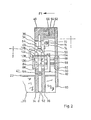
- FIG. 1 shows a partial section of a device according to the invention.
- a quick-action screwdriver 10 which is clamped vertically downward in a clamping element 14 with a clamping element 12 projecting downwards.
- the clamping element 14 is detachably fastened on the upper side of a carrier 16, which carrier 16 is fastened by means of a welded connection 18 to a container 20, perpendicular to its front side wall 22 (cf. FIG. 4).
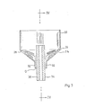
- the container 20 has an approximately rectangular shape and, as can be seen from FIG. 3, is provided at the bottom with obliquely downwardly inclined bottom walls 24 and 26 which not only run obliquely towards the center line, but also from the rear wall 28 front to the front side wall 22.
- the two bottom walls end in a bend 30 or 32, which leave a distance D between them, protrude through the two opposite wall parts 34 and 36 or protrude between the two bends 30 and 32.
- the two wall parts are by means of a bar 38 indicated on the left in FIG. 4 and a further bar 40 (see FIG. 2, which, depending on the production, with the two wall parts can be formed in one piece) kept at a distance, which distance is d.
- This distance d is larger by a certain amount than the screw body 42, but smaller than the screw head 44, so that, as can be seen from FIG. 4, the screw head slides on the upper edge 46 of the wall parts.
- the upper edges of the wall parts thus together form the feed channel for the individual screws.
- This feed trough which is also to be designated by the reference number 46, is inclined parallel to the bottom walls 24, 26 towards the screwing area, so that the individual screws can slide down the inclined plane while working.
- the inclined plane widens in the area of the screw-in point 48 in such a way that a circular passage 50 is formed, into which the feed trough 46 or the intermediate space 52 opens between the wall parts 34, 36, which area 50 is so large in diameter that the Heads 44 of the screws can fall through.
- a rod-like permanent magnet 54 which is oriented in the screw-in direction and which, as shown in FIG. 4, with its magnetic attraction pulls a screw 42/44 and precisely aligns it with the quick-assembly screwdriver 16. 4 that a screw pin 56 is clamped in the clamping element 12, the free end of which is provided with a screwdriver attachment 58 which is adapted to the slot or the cross recess on the screw head.
- the permanent magnet 54 is aligned so that the screw 42 adhering to it aligns with its axis with the axis of the screw pin 56.
- the device can be seen before the screwing process begins.
- the screwdriver 10 To screw it in, the screwdriver 10 must be pressed in the direction of the arrow F, the container 20 being moved over the wall parts. So that this can be carried out optimally, a holding wall 60 is fastened to the container 20 parallel to the wall parts 34, 36, on the free end of which a guide bar 62 is fastened parallel to the screwing-in direction, which in a c-shaped manner. Groove 64 ends.
- a T-shaped formation 66 is formed on the strip 40, which is guided in the recess 54 and slides it.
- On the carrier 16 there is also an angled guide element 68 which projects into and encompasses the path of the screw pin 56 such that the screw pin engages through an opening 70 in the guide element.
- a compression spring 72 is arranged, which is designed as a helical spring and engages around a pin 74 also serving as a guide. The guidance of the wall parts or onto the container and the quick-assembly screwdriver therefore takes place on the guide bar 62 or between the two bevels 30 and 32.
- the two components container with quick-action screwdriver and retaining wall 60
- edges 76 therefore have an inclination to the horizontal so that the device can be tilted or inclined Angle (X in the feed trough must not be too small, since otherwise the screws will not slide down due to the frictional force to be overcome between the edges 46 and the screw heads 44; the angle therefore results simply from the friction between heads 44 and edge 46.
- the feed trough does not need to be parallel to the drains who are 76; it has proven to be expedient for the manufacture of the wall parts 34, 36.
- Carrier 16 in the region of guide element 68 is screwed on an adjusting screw 78, a helical spring 80 being provided between its head and guide element 68.
- the screw 80 is used to set the maximum path between the fully deflected position (relaxed spring) and the fully screwed-in position (not shown in the figures).
- FIG. 2 shows a separating device which is known per se from VDI 3 240.
- a 1-shaped one is on the wall part 36 Support member 82 attached;
- a sheet metal plate 84 is provided on the outer surface of the opposite wall part 34, on which guide pins 86 and 88 are fastened, which guide pins extend through both wall parts 34, 36 and are firmly connected to a further guide plate 90 on the other side of the wall part 36.
- the guide plate 90 protrudes partially into the holding wall 60 and so that this is possible, the holding wall 60 has a recess 92, which is formed by pressing out a tab 94, which tab forms an inclined surface 96, which together with the when the quick-action screwdriver 10 is pressed down Holding wall 60 presses the guide plate 90 together with the guide rods 86 and 88 transversely to the wall parts 34, 36 in the direction of arrow F 1. Separating pins 98 and 100 are located between the guide pins 86 and 88.
- a tension spring 106 is arranged between an extension 102 on the guide plate 84 and a pin 104 on the element 82, which spring separates the separating device and in particular the two holding or guide plates 84 and 90 always applied in the opposite direction of the arrow F 1, so that the guide plate 84 always abuts the outer surface of the wall part 34.
- the separating pin 98 is now dimensioned such that it only slightly projects beyond the inner surface of the wall part 36, so that there is sufficient space between the inner surface of the wall part 34 and the end of the Vereirenzelungszapens 98 for the passage of a screw.
- the separating pin connected to the plate 84 is designed such that it covers the spacing d, so that in the position shown, a screw comes to rest in the space between the two separating pins and is held there.
- the quick-action screwdriver 10 is pressed downward, the tab or the inclined surface 96 runs onto the guide plate 90 and presses it in the direction of the arrow F1, so that the free end of the separating pin 98 is at least partially into the inner wall of the wall part 34, whereas the free end of the separating pin 100 retracts practically into the inner surface of the wall part 34 and thus the screw lying between the two separating pins clears the way down to the area 48.
- the wall parts 34 are dimensioned such that they lie below the base 24 in the state shown in the figure (relaxed coil spring 72). If the screwdriver 10 is pressed down together with the carrier and the container 20, the upper edge or the upper edge 46 of the wall parts 3 4 or 36 passes over the bottom 24, as can be seen for example from FIG. 3 can, in which a position is shown as it forms after completion of the screwing-in process.
- the upper edges 46 of the two wall parts 34 and 36 have, as can be seen, the floor parts or floor walls 24 and 26 clearly protruding.
- a boom spring-like steel spring 116 is provided on the inner wall or inner surface of the front wall 22, the free end 118 pointing towards the upper edge 46 is chamfered, so that each screw is also suitable Form is preceded.
Landscapes
- Engineering & Computer Science (AREA)
- Mechanical Engineering (AREA)
- Details Of Spanners, Wrenches, And Screw Drivers And Accessories (AREA)
Priority Applications (1)
| Application Number | Priority Date | Filing Date | Title |
|---|---|---|---|
| AT81103636T ATE9880T1 (de) | 1980-05-14 | 1981-05-12 | Automatische schraubenzufuehrvorrichtung. |
Applications Claiming Priority (2)
| Application Number | Priority Date | Filing Date | Title |
|---|---|---|---|
| DE3018382 | 1980-05-14 | ||
| DE3018382A DE3018382C2 (de) | 1980-05-14 | 1980-05-14 | Vorrichtung zum automatischen Zuführen von Schrauben zu dem Schraubstift eines Schraubers, insbesondere eines Schnellbauschraubers |
Publications (3)
| Publication Number | Publication Date |
|---|---|
| EP0039949A2 true EP0039949A2 (fr) | 1981-11-18 |
| EP0039949A3 EP0039949A3 (en) | 1982-02-10 |
| EP0039949B1 EP0039949B1 (fr) | 1984-10-17 |
Family
ID=6102369
Family Applications (1)
| Application Number | Title | Priority Date | Filing Date |
|---|---|---|---|
| EP81103636A Expired EP0039949B1 (fr) | 1980-05-14 | 1981-05-12 | Dispositif pour alimenter automatiquement en vis |
Country Status (4)
| Country | Link |
|---|---|
| US (1) | US4416172A (fr) |
| EP (1) | EP0039949B1 (fr) |
| AT (1) | ATE9880T1 (fr) |
| DE (1) | DE3018382C2 (fr) |
Cited By (2)
| Publication number | Priority date | Publication date | Assignee | Title |
|---|---|---|---|---|
| EP0292604A3 (en) * | 1987-05-28 | 1989-05-17 | Harald Zahn | Method and device for mechanically fastening roof sealing foils and insulating materials to roofs |
| GB2225974A (en) * | 1988-10-22 | 1990-06-20 | Yoshitaka Aoyama | Apparatus for feeding slender parts |
Families Citing this family (24)
| Publication number | Priority date | Publication date | Assignee | Title |
|---|---|---|---|---|
| US4662557A (en) * | 1985-04-29 | 1987-05-05 | Lee Lawrence L | Guide directed hammer having speed multiplying means |
| US4667545A (en) * | 1985-06-03 | 1987-05-26 | Gould Jr Frederick H | Screw gun automatic feed |
| US4875612A (en) * | 1988-08-05 | 1989-10-24 | Lee Lawrence L | Guided hammer |
| DE3922350A1 (de) * | 1989-07-07 | 1991-01-17 | Itw Ateco Gmbh | Magazin fuer schrauben |
| DE9016493U1 (fr) * | 1990-12-05 | 1991-03-14 | Paslode Gmbh, 6236 Eschborn, De | |
| DE4141961A1 (de) * | 1991-12-19 | 1993-06-24 | Wuerth Adolf Gmbh & Co Kg | Verschraubungsgeraet |
| US5372280A (en) * | 1992-08-29 | 1994-12-13 | Yoshitaka Aoyama | Chucking type parts feeding apparatus |
| US5398616A (en) * | 1993-08-06 | 1995-03-21 | Oak Industries, Inc. | Automatic rail fastener applicator |
| US5577447A (en) * | 1995-06-12 | 1996-11-26 | Oak Industries, Inc. | Automatiac railway fastener remover |
| US5975350A (en) * | 1997-06-19 | 1999-11-02 | Han; Ki Su | Screw feeding apparatus |
| US5904285A (en) * | 1997-11-26 | 1999-05-18 | Rayco Industries, Inc. | Nail transfer apparatus |
| GB2401079B (en) * | 2003-04-30 | 2005-04-27 | Black & Decker Inc | Screw feeder |
| US6945140B2 (en) | 2003-08-21 | 2005-09-20 | Black & Decker Inc. | Automatic screwfeeder |
| JP2005217136A (ja) * | 2004-01-29 | 2005-08-11 | Tdk Corp | 積層電子部品の整列方法及び装置 |
| US20080147240A1 (en) * | 2006-12-19 | 2008-06-19 | Gambro Bct Inc. | Apparatus for separating a composite liquid with process control on a centrifuge rotor |
| CN201227799Y (zh) * | 2008-07-03 | 2009-04-29 | 鸿富锦精密工业(深圳)有限公司 | 螺钉供给装置 |
| DE102011013878B4 (de) | 2011-03-11 | 2014-07-17 | Oleksandr Kozin | Vorrichtung zum automatischen Zuführen von Schrauben zu dem Schraubstift eines Schraubers, insbesondere eines Akkuschraubers |
| US11325235B2 (en) | 2016-06-28 | 2022-05-10 | Black & Decker, Inc. | Push-on support member for fastening tools |
| US11267114B2 (en) | 2016-06-29 | 2022-03-08 | Black & Decker, Inc. | Single-motion magazine retention for fastening tools |
| US11279013B2 (en) | 2016-06-30 | 2022-03-22 | Black & Decker, Inc. | Driver rebound plate for a fastening tool |
| US10987790B2 (en) | 2016-06-30 | 2021-04-27 | Black & Decker Inc. | Cordless concrete nailer with improved power take-off mechanism |
| US11400572B2 (en) | 2016-06-30 | 2022-08-02 | Black & Decker, Inc. | Dry-fire bypass for a fastening tool |
| US10926385B2 (en) * | 2017-02-24 | 2021-02-23 | Black & Decker, Inc. | Contact trip having magnetic filter |
| JP7338502B2 (ja) * | 2020-02-21 | 2023-09-05 | トヨタ自動車株式会社 | ボルト供給装置 |
Citations (4)
| Publication number | Priority date | Publication date | Assignee | Title |
|---|---|---|---|---|
| CH328832A (fr) * | 1955-02-07 | 1958-03-31 | F I E M M E Fabrication Import | Machine pour la pose automatique de vis et applications analogues |
| FR1242671A (fr) * | 1959-12-11 | 1960-09-30 | Calmore Buffalo Inc | Appareil pour la fourniture de vis, pour tournevis actionné mécaniquement |
| US2955630A (en) * | 1957-10-21 | 1960-10-11 | Russell Auto Feed Screwdrivers | Screw-driving machines |
| US3596821A (en) * | 1969-05-13 | 1971-08-03 | Irney Lee Rogers | Hopper-type fastener infeed device for fastener-driving tools |
Family Cites Families (8)
| Publication number | Priority date | Publication date | Assignee | Title |
|---|---|---|---|---|
| GB701848A (en) * | 1951-08-27 | 1954-01-06 | Skoda Works Plzen Nat Corp | An automatic device for delivering articles from hoppers |
| US2806219A (en) * | 1954-09-01 | 1957-09-17 | Arthur A Cavanaugh | Nailing machine |
| GB825223A (en) * | 1956-07-05 | 1959-12-09 | Nat Res Dev | Improvements in or relating to article feeding mechanisms |
| US2951516A (en) * | 1958-07-09 | 1960-09-06 | Gen Motors Corp | Fastener driving tool with hopper and feed means |
| DE2027642A1 (de) * | 1970-06-05 | 1971-12-09 | C.& E. Fein, 7000 Stuttgart | Motorisch angetriebenes Schrauberhandwerkzeug |
| US3820705A (en) * | 1972-08-07 | 1974-06-28 | W Beals | Nailing machine |
| DE2322324A1 (de) * | 1973-05-03 | 1974-11-14 | Erich Jaspes | Vorrichtung zum einschlagen von wellennaegeln oder dgl |
| US4101054A (en) * | 1976-09-30 | 1978-07-18 | Francis Edmund Frost | Pneumatic automatic screwfeeder |
-
1980
- 1980-05-14 DE DE3018382A patent/DE3018382C2/de not_active Expired
-
1981
- 1981-05-12 AT AT81103636T patent/ATE9880T1/de active
- 1981-05-12 EP EP81103636A patent/EP0039949B1/fr not_active Expired
- 1981-05-14 US US06/263,361 patent/US4416172A/en not_active Expired - Fee Related
Patent Citations (4)
| Publication number | Priority date | Publication date | Assignee | Title |
|---|---|---|---|---|
| CH328832A (fr) * | 1955-02-07 | 1958-03-31 | F I E M M E Fabrication Import | Machine pour la pose automatique de vis et applications analogues |
| US2955630A (en) * | 1957-10-21 | 1960-10-11 | Russell Auto Feed Screwdrivers | Screw-driving machines |
| FR1242671A (fr) * | 1959-12-11 | 1960-09-30 | Calmore Buffalo Inc | Appareil pour la fourniture de vis, pour tournevis actionné mécaniquement |
| US3596821A (en) * | 1969-05-13 | 1971-08-03 | Irney Lee Rogers | Hopper-type fastener infeed device for fastener-driving tools |
Cited By (3)
| Publication number | Priority date | Publication date | Assignee | Title |
|---|---|---|---|---|
| EP0292604A3 (en) * | 1987-05-28 | 1989-05-17 | Harald Zahn | Method and device for mechanically fastening roof sealing foils and insulating materials to roofs |
| GB2225974A (en) * | 1988-10-22 | 1990-06-20 | Yoshitaka Aoyama | Apparatus for feeding slender parts |
| GB2225974B (en) * | 1988-10-22 | 1993-03-31 | Yoshitaka Aoyama | Apparatus for feeding slender parts |
Also Published As
| Publication number | Publication date |
|---|---|
| EP0039949A3 (en) | 1982-02-10 |
| ATE9880T1 (de) | 1984-11-15 |
| DE3018382A1 (de) | 1981-11-26 |
| DE3018382C2 (de) | 1986-11-13 |
| US4416172A (en) | 1983-11-22 |
| EP0039949B1 (fr) | 1984-10-17 |
Similar Documents
| Publication | Publication Date | Title |
|---|---|---|
| EP0039949B1 (fr) | Dispositif pour alimenter automatiquement en vis | |
| DE10235226B4 (de) | Magazin zur Verwendung in einem Nagelgerät | |
| DE102008053329B4 (de) | Automatische Schraubenzuführvorrichtung für einen elektrischen Schraubenzieher | |
| DE3690023C1 (de) | Vorrichtung zum Eindrehen von Schrauben mit Unterlegscheiben | |
| EP0119542A1 (fr) | Outil pour chasser des clous | |
| DE1946587C3 (de) | Magazin an einem Nagler für kopflose Nägel | |
| EP0229195B1 (fr) | Magasin pour un outil motorisé apte à enfoncer des pointes ou clous ou similaires | |
| DE19538812A1 (de) | Vorrichtung zum Befestigen von Dachdichtungs- und Isoliermaterial auf Flachdächern | |
| DE2926881A1 (de) | Eintreibgeraet fuer koepfe und schaefte aufweisende befestigungsmittel | |
| EP0749808B1 (fr) | Dispositif de transport d'un magasin pour vis en forme de bande | |
| DE2138325A1 (de) | Lagerung für einen Bandförderer | |
| EP0346903A2 (fr) | Dispositif d'isolation d'objets du même type, en particulier de composants électroniques, comme les circuits intégrés | |
| DE3120093A1 (de) | Nietmaschine, insbesondere zum aufnieten der bremsbelaege auf den belagtraeger von bremsbacken | |
| CH656544A5 (de) | Vorrichtung zur laengsverstellung von skibindungsteilen. | |
| CH617862A5 (en) | Heel depressor for a ski binding and associated adjusting device | |
| DE3047599A1 (de) | "verfahren und vorrichtung zum anbringen einer hartmetallplatte am kopf eines spiralbohrers" | |
| EP0547638B1 (fr) | Outil de vissage | |
| EP0123805A1 (fr) | Appareil actionné par force pour enfoncer differents éléments d'attache | |
| EP1536081B1 (fr) | Gabarit de montage | |
| DE2163557A1 (de) | Magazin für eine Pistole zum Eintreiben von Nägeln | |
| DE3913956A1 (de) | Sicherheitsskibindung | |
| DE4141961A1 (de) | Verschraubungsgeraet | |
| DE2523551C2 (de) | Halterung für Beschläge | |
| DE1602698C (de) | Werkzeugfutter | |
| DE102004050538B4 (de) | Im Möbelbau zu verwendende Vorrichtung zum rechtwinkeligen Verbinden von zwei plattenartigen Profilteilen |
Legal Events
| Date | Code | Title | Description |
|---|---|---|---|
| PUAI | Public reference made under article 153(3) epc to a published international application that has entered the european phase |
Free format text: ORIGINAL CODE: 0009012 |
|
| AK | Designated contracting states |
Designated state(s): AT BE CH FR GB IT LU NL SE |
|
| PUAL | Search report despatched |
Free format text: ORIGINAL CODE: 0009013 |
|
| AK | Designated contracting states |
Designated state(s): AT BE CH FR GB IT LU NL SE |
|
| 17P | Request for examination filed |
Effective date: 19820727 |
|
| GRAA | (expected) grant |
Free format text: ORIGINAL CODE: 0009210 |
|
| AK | Designated contracting states |
Designated state(s): AT BE CH FR GB IT LI LU NL SE |
|
| PG25 | Lapsed in a contracting state [announced via postgrant information from national office to epo] |
Ref country code: IT Free format text: LAPSE BECAUSE OF FAILURE TO SUBMIT A TRANSLATION OF THE DESCRIPTION OR TO PAY THE FEE WITHIN THE PRESCRIBED TIME-LIMIT;WARNING: LAPSES OF ITALIAN PATENTS WITH EFFECTIVE DATE BEFORE 2007 MAY HAVE OCCURRED AT ANY TIME BEFORE 2007. THE CORRECT EFFECTIVE DATE MAY BE DIFFERENT FROM THE ONE RECORDED. Effective date: 19841017 Ref country code: SE Effective date: 19841017 Ref country code: NL Effective date: 19841017 |
|
| REF | Corresponds to: |
Ref document number: 9880 Country of ref document: AT Date of ref document: 19841115 Kind code of ref document: T |
|
| ET | Fr: translation filed | ||
| NLV1 | Nl: lapsed or annulled due to failure to fulfill the requirements of art. 29p and 29m of the patents act | ||
| PG25 | Lapsed in a contracting state [announced via postgrant information from national office to epo] |
Ref country code: AT Effective date: 19850512 |
|
| PG25 | Lapsed in a contracting state [announced via postgrant information from national office to epo] |
Ref country code: LU Free format text: LAPSE BECAUSE OF NON-PAYMENT OF DUE FEES Effective date: 19850531 Ref country code: CH Effective date: 19850531 Ref country code: LI Effective date: 19850531 |
|
| PLBE | No opposition filed within time limit |
Free format text: ORIGINAL CODE: 0009261 |
|
| STAA | Information on the status of an ep patent application or granted ep patent |
Free format text: STATUS: NO OPPOSITION FILED WITHIN TIME LIMIT |
|
| 26N | No opposition filed | ||
| REG | Reference to a national code |
Ref country code: CH Ref legal event code: PL |
|
| PGFP | Annual fee paid to national office [announced via postgrant information from national office to epo] |
Ref country code: FR Payment date: 19891130 Year of fee payment: 9 Ref country code: GB Payment date: 19891130 Year of fee payment: 9 |
|
| PGFP | Annual fee paid to national office [announced via postgrant information from national office to epo] |
Ref country code: BE Payment date: 19891212 Year of fee payment: 9 |
|
| PG25 | Lapsed in a contracting state [announced via postgrant information from national office to epo] |
Ref country code: GB Effective date: 19900512 |
|
| PG25 | Lapsed in a contracting state [announced via postgrant information from national office to epo] |
Ref country code: BE Effective date: 19900531 |
|
| BERE | Be: lapsed |
Owner name: MEDINGER WALTER Effective date: 19900531 |
|
| GBPC | Gb: european patent ceased through non-payment of renewal fee | ||
| PG25 | Lapsed in a contracting state [announced via postgrant information from national office to epo] |
Ref country code: FR Effective date: 19910131 |
|
| REG | Reference to a national code |
Ref country code: FR Ref legal event code: ST |