EP0346903A2 - Dispositif d'isolation d'objets du même type, en particulier de composants électroniques, comme les circuits intégrés - Google Patents
Dispositif d'isolation d'objets du même type, en particulier de composants électroniques, comme les circuits intégrés Download PDFInfo
- Publication number
- EP0346903A2 EP0346903A2 EP89110891A EP89110891A EP0346903A2 EP 0346903 A2 EP0346903 A2 EP 0346903A2 EP 89110891 A EP89110891 A EP 89110891A EP 89110891 A EP89110891 A EP 89110891A EP 0346903 A2 EP0346903 A2 EP 0346903A2
- Authority
- EP
- European Patent Office
- Prior art keywords
- stop element
- control circuit
- conveying direction
- frequency
- plunger
- Prior art date
- Legal status (The legal status is an assumption and is not a legal conclusion. Google has not performed a legal analysis and makes no representation as to the accuracy of the status listed.)
- Withdrawn
Links
- 230000007423 decrease Effects 0.000 claims description 2
- 230000001154 acute effect Effects 0.000 claims 1
- 238000000605 extraction Methods 0.000 claims 1
- 238000000926 separation method Methods 0.000 description 14
- 238000012360 testing method Methods 0.000 description 4
- 238000004519 manufacturing process Methods 0.000 description 2
- 230000004888 barrier function Effects 0.000 description 1
- 230000006835 compression Effects 0.000 description 1
- 238000007906 compression Methods 0.000 description 1
- 238000010276 construction Methods 0.000 description 1
- 230000001419 dependent effect Effects 0.000 description 1
- 238000011161 development Methods 0.000 description 1
- 230000018109 developmental process Effects 0.000 description 1
- 230000009977 dual effect Effects 0.000 description 1
- 230000007257 malfunction Effects 0.000 description 1
- 230000036316 preload Effects 0.000 description 1
- 230000000284 resting effect Effects 0.000 description 1
- 238000004904 shortening Methods 0.000 description 1
- 230000003068 static effect Effects 0.000 description 1
- 230000001960 triggered effect Effects 0.000 description 1
Images

Classifications
-
- H—ELECTRICITY
- H05—ELECTRIC TECHNIQUES NOT OTHERWISE PROVIDED FOR
- H05K—PRINTED CIRCUITS; CASINGS OR CONSTRUCTIONAL DETAILS OF ELECTRIC APPARATUS; MANUFACTURE OF ASSEMBLAGES OF ELECTRICAL COMPONENTS
- H05K13/00—Apparatus or processes specially adapted for manufacturing or adjusting assemblages of electric components
- H05K13/0084—Containers and magazines for components, e.g. tube-like magazines
-
- H—ELECTRICITY
- H05—ELECTRIC TECHNIQUES NOT OTHERWISE PROVIDED FOR
- H05K—PRINTED CIRCUITS; CASINGS OR CONSTRUCTIONAL DETAILS OF ELECTRIC APPARATUS; MANUFACTURE OF ASSEMBLAGES OF ELECTRICAL COMPONENTS
- H05K13/00—Apparatus or processes specially adapted for manufacturing or adjusting assemblages of electric components
- H05K13/02—Feeding of components
-
- H—ELECTRICITY
- H05—ELECTRIC TECHNIQUES NOT OTHERWISE PROVIDED FOR
- H05K—PRINTED CIRCUITS; CASINGS OR CONSTRUCTIONAL DETAILS OF ELECTRIC APPARATUS; MANUFACTURE OF ASSEMBLAGES OF ELECTRICAL COMPONENTS
- H05K13/00—Apparatus or processes specially adapted for manufacturing or adjusting assemblages of electric components
- H05K13/04—Mounting of components, e.g. of leadless components
- H05K13/043—Feeding one by one by other means than belts
-
- Y—GENERAL TAGGING OF NEW TECHNOLOGICAL DEVELOPMENTS; GENERAL TAGGING OF CROSS-SECTIONAL TECHNOLOGIES SPANNING OVER SEVERAL SECTIONS OF THE IPC; TECHNICAL SUBJECTS COVERED BY FORMER USPC CROSS-REFERENCE ART COLLECTIONS [XRACs] AND DIGESTS
- Y10—TECHNICAL SUBJECTS COVERED BY FORMER USPC
- Y10T—TECHNICAL SUBJECTS COVERED BY FORMER US CLASSIFICATION
- Y10T29/00—Metal working
- Y10T29/53—Means to assemble or disassemble
- Y10T29/5313—Means to assemble electrical device
-
- Y—GENERAL TAGGING OF NEW TECHNOLOGICAL DEVELOPMENTS; GENERAL TAGGING OF CROSS-SECTIONAL TECHNOLOGIES SPANNING OVER SEVERAL SECTIONS OF THE IPC; TECHNICAL SUBJECTS COVERED BY FORMER USPC CROSS-REFERENCE ART COLLECTIONS [XRACs] AND DIGESTS
- Y10—TECHNICAL SUBJECTS COVERED BY FORMER USPC
- Y10T—TECHNICAL SUBJECTS COVERED BY FORMER US CLASSIFICATION
- Y10T29/00—Metal working
- Y10T29/53—Means to assemble or disassemble
- Y10T29/53478—Means to assemble or disassemble with magazine supply
Definitions
- the invention relates to a device according to the preamble of claim 1.
- DE-OS 32 17 531 a device for separating electronic components is described and shown, which is formed in the direction of flow of the existing conveyor channel for the components elastic band, which replaces a wall section of the conveyor channel and in contact with the foremost components one existing row of components in the conveyor channel.
- the components can be separated, the device being independent of the respective length of the components , because the conveyor belt has different switch-on times Lengths of the components can be taken into account.
- a relatively large wear of the elastic conveyor belt is to be expected, so that such a relatively often has to be replaced with a considerable amount of work and time.
- such a separating device is relatively space-consuming, and it is therefore difficult to integrate it into a plurality of conveying channels lying side by side and forming a magazine.
- two stop elements which are adjustable transversely to the conveying channel and interact with two successive components are provided, of which the first stop element has a stop for the respective first component forms while the second stop element presses on the component immediately behind.
- the two stop elements are driven so that only one stop element is immersed in the conveyor channel.
- the separation device is dependent on the length of the components.
- the invention has for its object to design a device of the type mentioned in such a way that, while ensuring a relatively long service life, it is suitable for use in particular in terms of length of different components.
- the dwell time of the respective first component in the area of the stop element caused by the effectiveness of the stop element is changed as a function of the resulting or a desired clock frequency at the removal point or a further processing point.
- the dwell time and thus the separation speed can be adapted to a constant or variable arrival or removal repetition frequency, which results in the separation after the end of the dwell time of the first component in the area of the stop element.
- the separating device can be adjusted to components of different lengths. Due to the adaptability of the separation to different clock frequencies at the point of removal of further processing It is also possible to adapt to different working speeds of the processing or testing device downstream of the separating device.
- the solution according to the invention is reliable, of simple and inexpensive construction and of a long service life, since the stop element exhibits only negligible wear, if any.
- the singulation frequency the frequency of the pulses with which the stop element is applied against the component to be separated, the contact or pressure time during which the stop element is in contact with the component to be separated, and / or to change the release time in which the stop element is not in contact with the component.
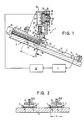
- the separating device is assigned to a magazine for IC's 3, generally designated 2.
- the magazine 2 is assigned to a device (not shown) for testing electronic components, here the IC's 3, and it has a plurality of guide or conveying channels 4 running parallel to one another, which are arranged on an inclined magazine plate 5. The inclination is so great that the IC's 3 slide down in the conveying channels 4 due to their own weight.
- a separation device 1 is assigned to each conveyor channel 4.
- the magazine 2 or the delivery channels 4 are set up to receive ICs 3 which have a platelet shape with a plastic housing and contact elements arranged over the entire circumference.
- ICs are known under the short name PLCC.
- the contact elements designated 6 project over a broad side of the ICs. In the present embodiment, this broadside is directed downwards, i.e. the IC's 3 lie or slide on the contact elements 6 pointing downward, while the upper broad side is free of contact elements 6.
- the conveyor channels 4 are each formed or delimited by two lateral and an upper guide bar 7, 8, which results in the respective conveyor channel 4 in which the ICs are accommodated with play.
- the conveying channels 4 extend from the separating devices 1 arranged next to one another over a certain distance up to a removal point 9 for the IC's 3, each of which is defined by a stop piece 11 delimiting the delivery channel 4, to which the isolated IC's 3 slide.
- a sensor 12 preferably in the form of a light barrier, is provided, which is able to emit a signal when an isolated IC 3 is present at the removal point 9.
- magazine bars 13 are arranged in line with the conveying channels 4, which are indicated and can be used in connections or sockets (not shown in detail) and can therefore be replaced, by an empty magazine bar 13 against a magazine bar 13 filled with ICs 3 exchange.
- Each separating device 1 has a stop element, generally designated 15, arranged above the associated conveying channel 4 in the form of a pin-shaped plunger 16 which extends transversely to the conveying channel 4 and can be moved up and down, and which passes through an opening 17 in the upper guide bar 8 into the cross section of the conveying channel 4 immerse and can stop by contact with the IC 3 arranged in this area, so that it does not slip.
- the plunger 16 is designed as an armature of an electrical coil 18 or is connected to such an armature.
- the coil former 18 is fastened on the inside to a leg of an angular or U-shaped holder piece 19, which is fastened to an intermediate plate 22 by means of screws 21.
- the intermediate plate 22 is also fastened to a guide bracket 24 by means of two screws 23, the screws 23 passing through the fastening part of the guide bracket 24 in elongated holes 25.
- the guide bracket 24 is also fastened to a fastening plate 28, the elongated holes 25, 27 extending essentially vertically.
- the stop element 15 transversely to the magazine plate 5 in terms of its height (screw 26) and its stroke (screws 23) in and fix.
- the fastening plate 28 is part of a holder 30 which is arranged and held on the magazine plate 5 or the guide strips 7, 8.
- the plunger 16 surrounds the guide leg 29 of the guide bracket 24 in a guide hole 31, whereby it receives a secure guide with the guide hole also arranged in the lower leg 32 of the holder 19 but not shown.
- a compression spring 33 is clamped between the legs 29, 32, which is supported on the leg 32 and acts against an annular shoulder 34 of the plunger 16 resting on the guide leg 29.
- the plunger 16 is thus biased into its extended stroke end position.
- This stroke end position is to be arranged lower than the upper side 35 of the IC 3 to be separated, so that the stop element 15 acts with the prestress against the IC 3 and presses it against its base and prevents it from sliding further.
- the preload is to be dimensioned so large that even when there is a long row of ICs 3 in the magazine rod 13 and the resulting weight, the IC 3 to be separated can be safely stopped.
- the stop element 15 When the respective conveyor channel 4 is loaded with new ICs, the first IC 3 to be separated abuts the stop element 15, which thus acts as a stop.
- the stop element 15 is always at the top 35 of the one to be separated after the separation has started IC's 3, the latter being able to assume a position which is indicated as 3.1 in FIG. 1. However, this position is not fixed, it can vary.
- the sensor 12 is connected by an electrical control line to a processor P which is connected by a further electrical control line via a current control circuit 30 to the electromagnetic drive of the plunger 16, generally designated 36, and controls the plunger 16 in such a way that the plunger 16 with a certain Cycle frequency stands out from the IC 3 to be separated and presses again against the IC due to the spring force.
- a processor P which is connected by a further electrical control line via a current control circuit 30 to the electromagnetic drive of the plunger 16, generally designated 36, and controls the plunger 16 in such a way that the plunger 16 with a certain Cycle frequency stands out from the IC 3 to be separated and presses again against the IC due to the spring force.
- the dwell time of the IC 3 to be separated can be in the area of the stop element 15 and thus the speed of the separation control or regulate.
- the speed of the separation is controlled in accordance with the arrival repetition frequency or the withdrawal repetition frequency at the withdrawal point 9. That is, the separation is adapted to the passage of the ICs 3 after the separation device 1, and it can also be adapted to the speed of removal at the removal point 9.
- the arrangement is preferably made so that the stop element 15 contacts each IC 3 to be separated at least twice or three times. As a result, since a clear position of the IC 3 to be separated relative to the stop element 16 is not predetermined, it is prevented that, in the presence of a relatively high pressure resulting from a long row of IC 3, which is effective in the conveying direction generally designated 37, the pressure to be separated IC 3 following IC 3 accidentally slips.
- the plunger 16 Since the plunger 16 is urged into its stop position by the spring force, the stop function is ensured even in the event of a power failure, so that the separating device 1 can continue to operate without interruption when current occurs.
- the separation is preferably controlled by lengthening or shortening either the pressing time of the plunger 16 or the lifting time of the plunger 16. This works in detail as follows. After a single IC 3 has left the stop element 15, the plunger 16 is pressed against the IC 3 that has slipped beneath it at least twice in the sense of the clock sequence, the sensor 12 checking whether the IC 3 that has left has arrived. Then, when the sensor 12 signals the removal of the IC 3 at the removal point 9, the IC 3 now to be separated is released. However, if the IC 12 does not signal even with the longest pressing time (for long ICs), the processor P automatically determines that the conveyor channel 4 in question is empty or at least one IC 3 is jammed in it. Then a signal can be triggered and / or the one or the next delivery channel 4 can also be activated and the stop element 15 can be controlled by the processor P.
- the IC 3 is also possible for the IC 3 to be separated to be released before the sensor 12 signals the removal at the removal point 9.
- the processor P is programmed accordingly.
- the shortest cycle frequency is stored and used as a control criterion when commissioning one or the next conveyor channel 4.
- a separating device 1 is created, which is completely independent of the length 1 of the ICs 3 and also their width b or their weight.
- the stop device having the stop element 15 such that the longitudinal axis 38 of the plunger 16 is inclined in or against the conveying direction 37, cf. Fig. 1, in which there is an inclination against the conveying direction.
- the stop element 15 exerts a longitudinal movement on the latter when it comes into contact with the IC 3 to be separated, as a result of which static friction is eliminated or at least reduced and an improved throughput is achieved.
- the exemplary embodiment according to FIGS. 3 and 4 basically works in accordance with the first exemplary embodiment.
- the separating device 1 is arranged below the associated conveying channel 4, that is to say the holder 30 is fastened to the underside of the magazine plate 5, the plunger 16 being moved from below into the conveying channel 4 through an opening 39 in the magazine plate 5, towards the underside the IC's designated here 41 acts and presses them against the upper guide bar 8 during the stop function.
- this association serves celling device 1 for separating so-called “dual in line” ICs 41, which have contact elements 42 only on both sides.
- the contact elements 42 are directed downward, immersing them in two guide grooves 43 of the conveying channel 4.
- the upper guide strips 8 are fastened on the underside to support strips 44 directed transversely to the conveying channels 4 by means of screws 45, which carry several or all of the existing upper guide strips 8.
- the support strips 44 are preferably arranged such that they can be adjusted in height in a manner not shown, so that the height h of the conveying channels 4 can be adjusted and adapted to the ICs to be processed.
Landscapes
- Engineering & Computer Science (AREA)
- Manufacturing & Machinery (AREA)
- Microelectronics & Electronic Packaging (AREA)
- Special Conveying (AREA)
- Feeding Of Articles To Conveyors (AREA)
- Testing Of Individual Semiconductor Devices (AREA)
Applications Claiming Priority (2)
| Application Number | Priority Date | Filing Date | Title |
|---|---|---|---|
| DE3820540A DE3820540A1 (de) | 1988-06-16 | 1988-06-16 | Vorrichtung zur vereinzelung von gleichartigen gegenstaenden, insbesondere elektronischen bauelementen, wie ic's |
| DE3820540 | 1988-06-16 |
Publications (2)
| Publication Number | Publication Date |
|---|---|
| EP0346903A2 true EP0346903A2 (fr) | 1989-12-20 |
| EP0346903A3 EP0346903A3 (fr) | 1990-12-27 |
Family
ID=6356695
Family Applications (1)
| Application Number | Title | Priority Date | Filing Date |
|---|---|---|---|
| EP19890110891 Withdrawn EP0346903A3 (fr) | 1988-06-16 | 1989-06-15 | Dispositif d'isolation d'objets du même type, en particulier de composants électroniques, comme les circuits intégrés |
Country Status (3)
| Country | Link |
|---|---|
| US (1) | US4993588A (fr) |
| EP (1) | EP0346903A3 (fr) |
| DE (1) | DE3820540A1 (fr) |
Cited By (3)
| Publication number | Priority date | Publication date | Assignee | Title |
|---|---|---|---|---|
| FR2670191A1 (fr) * | 1990-12-05 | 1992-06-12 | Nitto Kogyo Kk | Appareil automatique de separation et d'amenee de puces. |
| DE102005058704B3 (de) * | 2005-12-08 | 2007-07-12 | Multitest Elektronische Systeme Gmbh | Führungsbahn für elektronische Bauelemente |
| CN104760828A (zh) * | 2010-12-08 | 2015-07-08 | 联达科技设备私人有限公司 | 用于基于真空调节部件流动和单个化的系统、装置和方法 |
Families Citing this family (11)
| Publication number | Priority date | Publication date | Assignee | Title |
|---|---|---|---|---|
| JPH03291000A (ja) * | 1990-04-07 | 1991-12-20 | Murata Mfg Co Ltd | 電子部品チップ整列装置 |
| US5425473A (en) * | 1991-06-10 | 1995-06-20 | Kval, Inc. | Screw feeder |
| US5339983A (en) * | 1993-05-18 | 1994-08-23 | Multifastener Corporation | Dual pawl spool feeder |
| US5826696A (en) * | 1994-08-11 | 1998-10-27 | Walter Grassle Gmbh | Apparatus for separating small articles |
| DE19511948A1 (de) * | 1994-08-11 | 1996-02-15 | Graessle Walter Gmbh | Vorrichtung zum Vereinzeln von kleinen Gegenständen |
| US5594985A (en) * | 1995-05-08 | 1997-01-21 | Texas Instruments Incorporated | End pin extractor for semiconductor storage tube |
| US5997388A (en) * | 1997-08-11 | 1999-12-07 | Micron Electronics, Inc. | Apparatus for removing marks from integrated circuit devices |
| US5938508A (en) * | 1997-08-11 | 1999-08-17 | Micron Electronics, Inc. | Method for removing marks from integrated circuit devices and devices so processed |
| DE19944290C2 (de) | 1999-09-15 | 2002-01-31 | Siemens Ag | Vorrichtung zum Zuführen von elektronischen Bauteilen mit Maßnahmen gegen Fehl-bestückung |
| US6371715B1 (en) * | 2000-07-03 | 2002-04-16 | Advanced Micro Devices, Inc. | Automated tube to tube transfer of a predetermined number of IC packages for various types of IC packages |
| US9975708B2 (en) | 2016-03-16 | 2018-05-22 | Texas Instruments Incorporated | Transfer track stopper for packaged integrated circuits |
Family Cites Families (13)
| Publication number | Priority date | Publication date | Assignee | Title |
|---|---|---|---|---|
| US2703894A (en) * | 1949-10-18 | 1955-03-15 | Snow Mfg Company | Nut tapping machine responsive to feed of work piece |
| US2979229A (en) * | 1958-02-24 | 1961-04-11 | Alliance Mfg Co | Object dispenser having receiver-actuated object release means |
| US3253734A (en) * | 1965-02-08 | 1966-05-31 | Western Electric Co | Methods of and apparatus for detecting dimensional characteristics of articles |
| JPS6139695Y2 (fr) * | 1980-05-19 | 1986-11-13 | ||
| FR2492623A1 (fr) * | 1980-10-29 | 1982-04-30 | Inst Tech Cereales Fourrages | Element semeur et semoir pour parcelles experimentales |
| DE3217531C2 (de) * | 1982-05-10 | 1985-01-03 | Ekkehard Ing.(Grad.) 8011 Zorneding Ueberreiter | Vorrichtung zum Prüfen und Sortieren von länglichen elektronischen Bauteilen, insbesondere von integrierten Chips |
| US4567652A (en) * | 1982-11-18 | 1986-02-04 | Reliability Incorporated | Burn-in board loader |
| US4690302A (en) * | 1985-02-25 | 1987-09-01 | E. I. Du Pont De Nemours And Company | Package and apparatus for dispensing electrical connectors |
| DE3531143A1 (de) * | 1985-06-04 | 1986-12-04 | Hans-Heinrich 8000 München Willberg | Einrichtung zum pruefen und sortieren von elektronischen bauelementen, insbesondere integrierten chips |
| KR900001090B1 (ko) * | 1985-07-17 | 1990-02-26 | 후지쓰가부시끼가이샤 | 전자부품 삽입장치 |
| US4775279A (en) * | 1985-12-11 | 1988-10-04 | American Tech Manufacturing, Inc. | Method and apparatus for loading/unloading dip devices |
| US4703858A (en) * | 1986-01-02 | 1987-11-03 | Multitest Elektronische Systeme Gmbh | Apparatus for testing and sorting oblong, electronic components, more particularly integrated chips |
| DE3638430A1 (de) * | 1986-11-11 | 1988-05-19 | Multitest Elektronische Syst | Vorrichtung zum testen und sortieren von elektronischen bauelementen, insbesondere ic's |
-
1988
- 1988-06-16 DE DE3820540A patent/DE3820540A1/de not_active Withdrawn
-
1989
- 1989-06-13 US US07/365,761 patent/US4993588A/en not_active Expired - Fee Related
- 1989-06-15 EP EP19890110891 patent/EP0346903A3/fr not_active Withdrawn
Cited By (3)
| Publication number | Priority date | Publication date | Assignee | Title |
|---|---|---|---|---|
| FR2670191A1 (fr) * | 1990-12-05 | 1992-06-12 | Nitto Kogyo Kk | Appareil automatique de separation et d'amenee de puces. |
| DE102005058704B3 (de) * | 2005-12-08 | 2007-07-12 | Multitest Elektronische Systeme Gmbh | Führungsbahn für elektronische Bauelemente |
| CN104760828A (zh) * | 2010-12-08 | 2015-07-08 | 联达科技设备私人有限公司 | 用于基于真空调节部件流动和单个化的系统、装置和方法 |
Also Published As
| Publication number | Publication date |
|---|---|
| US4993588A (en) | 1991-02-19 |
| EP0346903A3 (fr) | 1990-12-27 |
| DE3820540A1 (de) | 1989-12-21 |
Similar Documents
| Publication | Publication Date | Title |
|---|---|---|
| DE2744235C2 (fr) | ||
| EP0346903A2 (fr) | Dispositif d'isolation d'objets du même type, en particulier de composants électroniques, comme les circuits intégrés | |
| EP0039949B1 (fr) | Dispositif pour alimenter automatiquement en vis | |
| DE1103240B (de) | Foerdervorrichtung fuer ein Montagesystem mit einer Anzahl von Arbeitsstellen zum Montieren von elektrischen Schaltungsbauteilen auf Werkstuecke, wie z. B. Schaltungstafeln | |
| EP0758285B1 (fr) | Dispositif destine a etre utilise dans une presse pour l'amenee d'elements de fixation et leur fixation par pressage dans des pieces | |
| DE2842053A1 (de) | Vibrations-zufuehrungseinrichtung | |
| DE4010697A1 (de) | Montagestation | |
| DE3023449A1 (de) | Vorrichtung zum transportieren von kleinteilen | |
| EP0144781B1 (fr) | Installation pour trier et distribuer des petites pièces ayant une bride et un manche | |
| DE102017102618B4 (de) | Zuführeinrichtung | |
| DE2615364C2 (de) | Einrichtung zum Widerstandsanschweißen von Kontaktmetallrohlingen an einer Anbringungsfläche | |
| DE3047599A1 (de) | "verfahren und vorrichtung zum anbringen einer hartmetallplatte am kopf eines spiralbohrers" | |
| EP0116922B1 (fr) | Conyoyeur vibrant longitudinal | |
| DE2004931A1 (de) | Vorrichtung zum Zuführen von Stabstahl | |
| DE976498C (de) | Vorrichtung zum Zusammensetzen von kleineren Metallteilen aus ihren Einzelteilen | |
| DE2616509C2 (de) | Vorrichtung zum Vereinzelnen loser elektrischer Bauelemente | |
| DE3917310A1 (de) | Pruef- oder messvorrichtung | |
| EP0162188A1 (fr) | Dispositif de contrôle pour tiges pouvant rouler | |
| DE4001761C2 (fr) | ||
| DE69214106T2 (de) | Knopfzuführung für eine Knopfansatzmaschine | |
| DE68906860T2 (de) | Vibrationsfoerderer. | |
| DE3140163C2 (de) | Meßautomat für piezokeramische Wandler | |
| DE19505991C2 (de) | Vorrichtung zum Zuführen von mit Gewindekernöffnungen versehenen Stanz-Formteilen | |
| DE19827459C1 (de) | Vorrichtung und Verfahren zum Fördern elektronischer Bauelemente | |
| EP1704939A1 (fr) | Dispositif d'alimentation de fils, en particulier vers machines de soudage |
Legal Events
| Date | Code | Title | Description |
|---|---|---|---|
| PUAI | Public reference made under article 153(3) epc to a published international application that has entered the european phase |
Free format text: ORIGINAL CODE: 0009012 |
|
| AK | Designated contracting states |
Kind code of ref document: A2 Designated state(s): DE FR GB |
|
| PUAL | Search report despatched |
Free format text: ORIGINAL CODE: 0009013 |
|
| AK | Designated contracting states |
Kind code of ref document: A3 Designated state(s): DE FR GB |
|
| 17P | Request for examination filed |
Effective date: 19910621 |
|
| STAA | Information on the status of an ep patent application or granted ep patent |
Free format text: STATUS: THE APPLICATION IS DEEMED TO BE WITHDRAWN |
|
| 18D | Application deemed to be withdrawn |
Effective date: 19921231 |