EP0039768B1 - Projektionsschirmeinrichtung - Google Patents
Projektionsschirmeinrichtung Download PDFInfo
- Publication number
- EP0039768B1 EP0039768B1 EP81102272A EP81102272A EP0039768B1 EP 0039768 B1 EP0039768 B1 EP 0039768B1 EP 81102272 A EP81102272 A EP 81102272A EP 81102272 A EP81102272 A EP 81102272A EP 0039768 B1 EP0039768 B1 EP 0039768B1
- Authority
- EP
- European Patent Office
- Prior art keywords
- lens
- image
- forming element
- projection
- textured
- Prior art date
- Legal status (The legal status is an assumption and is not a legal conclusion. Google has not performed a legal analysis and makes no representation as to the accuracy of the status listed.)
- Expired
Links
- 230000000694 effects Effects 0.000 claims description 7
- 230000003287 optical effect Effects 0.000 claims description 7
- 210000001747 pupil Anatomy 0.000 claims description 5
- 239000011521 glass Substances 0.000 claims description 4
- 230000000737 periodic effect Effects 0.000 claims description 3
- 229920002972 Acrylic fiber Polymers 0.000 claims description 2
- 238000009792 diffusion process Methods 0.000 abstract 2
- 238000003384 imaging method Methods 0.000 description 2
- 238000011161 development Methods 0.000 description 1
- 230000018109 developmental process Effects 0.000 description 1
- 230000002688 persistence Effects 0.000 description 1
- 230000001105 regulatory effect Effects 0.000 description 1
Images
Classifications
-
- G—PHYSICS
- G03—PHOTOGRAPHY; CINEMATOGRAPHY; ANALOGOUS TECHNIQUES USING WAVES OTHER THAN OPTICAL WAVES; ELECTROGRAPHY; HOLOGRAPHY
- G03B—APPARATUS OR ARRANGEMENTS FOR TAKING PHOTOGRAPHS OR FOR PROJECTING OR VIEWING THEM; APPARATUS OR ARRANGEMENTS EMPLOYING ANALOGOUS TECHNIQUES USING WAVES OTHER THAN OPTICAL WAVES; ACCESSORIES THEREFOR
- G03B21/00—Projectors or projection-type viewers; Accessories therefor
- G03B21/54—Accessories
- G03B21/56—Projection screens
- G03B21/60—Projection screens characterised by the nature of the surface
- G03B21/62—Translucent screens
-
- G—PHYSICS
- G03—PHOTOGRAPHY; CINEMATOGRAPHY; ANALOGOUS TECHNIQUES USING WAVES OTHER THAN OPTICAL WAVES; ELECTROGRAPHY; HOLOGRAPHY
- G03B—APPARATUS OR ARRANGEMENTS FOR TAKING PHOTOGRAPHS OR FOR PROJECTING OR VIEWING THEM; APPARATUS OR ARRANGEMENTS EMPLOYING ANALOGOUS TECHNIQUES USING WAVES OTHER THAN OPTICAL WAVES; ACCESSORIES THEREFOR
- G03B21/00—Projectors or projection-type viewers; Accessories therefor
- G03B21/54—Accessories
- G03B21/56—Projection screens
- G03B21/562—Screens moving during projection
Definitions
- the invention relates to a projection screen device for transmitted light observation of images, with two optical elements arranged directly parallel to one another and movable relative to one another to avoid flicker effects.
- a projection screen is known from DE-A-1945486, which consists of two scattering disks arranged directly one above the other and moved relative to one another.
- this arrangement has the disadvantage that the second lens causes a relatively large loss of light.
- Projection screens with two mutually movable diffusing screens with different scattering capacities are known from DE-A-21 38 340. Although this device eliminates the flickering effect, the loss of light only to a certain extent.
- DE-B-27 50 891 shows a projection screen device in which a Fresnel lens is arranged parallel to a diffusing screen in order to achieve optimum image brightness. Since there is no relative movement between the lens and the Fresnel lens, the flicker effect is not eliminated.
- the invention has for its object to provide a projection screen device of the type mentioned above, in which said flicker effect can be eliminated without any significant loss of light.
- the one optical element is a structured, moving imaging element for imaging the exit pupil of a projection objective in the direction of the entrance pupil of the observer and the other optical element is a diffusing disk arranged in a stationary manner for this purpose.
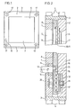
- FIG. 1 and 2 show a projection screen device according to the invention, in which two rectangular plates 1, 2 are rigidly connected to one another in parallel by means of two cross members 3 and fastening elements 4. Both plates 1, 2 each have a rectangular opening 5, 6 in the middle for viewing transmitted light images which are imaged on a rectangular diffuser 7 closing the opening 6 of plate 2 by means of a projection device (not shown).
- Another rectangular plate 8 is movably arranged between the two plates 1, 2 and has a Fresnel lens 10, 11 or a plate with a honeycomb structure (shown schematically) in an opening 9 corresponding to the openings 5, 6.
- the middle plate experiences a periodic translational movement in two directions parallel to the lens 7 from a motor, not shown, via a shaft 13 mounted in bearings 14, the eccentric 15 of which drives the plate 8 via bearings 16.
- This two-dimensional periodic translatory movement of the plate 8 is brought about by a two-dimensional linear guide 17 which consists of a linear longitudinal guide 18, a linear transverse guide 19 and a two-dimensional counter bearing 20.
- the relative movement between the lens 7 and the Fresnel lens 10, 11 or the honeycomb-structured plate can be regulated.
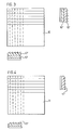
- the Fresnel lens 10 according to FIG. Consists of two rectangularly crossed cylindrical Fresnel lenses 10 ', 10 "with a parallel groove structure.
- the Fresnel lens 11 according to FIG. 4 has a parallel groove structure 11' on one surface, which is perpendicular to a parallel groove structure 11" on the other surface .
- a Fresnel lens (not shown) is proposed, which has two parallel, perpendicular groove structures on one surface, each of which likewise produces a cylindrical image.
- the honeycomb structure consists, for example, of small prisms or lenses.
- a projection screen device can also have a fixed diffusing screen and a Fresnel lens rotating eccentrically parallel to it in a manner not shown.
- the scattering surface of the lens 7 preferably faces the structured surfaces of the Fresnel lens 10, 11 or the honeycomb-structured plate, the lens 7 being arranged behind them in the direction of projection.
- the lens 7 can be made of glass, for example, and the Fresnel lens 10, 11 or the honeycomb-structured plate can be made of glass or acrylic plastic.
Landscapes
- Physics & Mathematics (AREA)
- General Physics & Mathematics (AREA)
- Overhead Projectors And Projection Screens (AREA)
- Massaging Devices (AREA)
- Optical Elements Other Than Lenses (AREA)
Description
- Die Erfindung betrifft eine Projektionsschirmeinrichtung für die Durchlichtbeobachtung von Bildern, mit zwei unmittelbar parallel zueinander angeordneten, relativ zueinander beweglichen optischen Elementen zur Vermeidung von Flimmereffekten.
- Derartige Projektionsschirmeinrichtungen sind bereits bekannt. Sie weisen jedoch den Nachteil auf, daß das Bild auf der Streuscheibe durch ein vielfarbiges Flimmern stark beeinträchtigt wird.
- Zur Beseitigung dieses Flimmereffekts ist vorgeschlagen worden, die Streuscheibe rotieren zu lassen ; nachteilig erweist sich hierbei die relativ hohe Winkelgeschwindigkeit, um die Visionspersistenz des Auges zu überschreiten.
- Aus der DE-A-1945486 ist ein Projektionsschirm bekannt, der aus zwei unmittelbar übereinander angeordneten und relativ zueinander bewegten Streuscheiben besteht. Diese Anordnung besitzt aber den Nachteil, daß die zweite Streuscheibe eine relativ große Lichteinbuße hervorruft.
- Projektionsschirme mit zwei gegenseitig bewegbaren Streuscheiben unterschiedlichen Streuvermögens sind aus der DE-A-21 38 340 bekannt. Diese Einrichtung beseitigt zwar den Flimmereffekt, die Lichteinbuße aber nur in einem bestimmten Ausmaße.
- In der DE-B-27 50 891 ist eine Projektionsschirmeinrichtung dargestellt, bei der parallel zu einer Streuscheibe eine Fresnellinse zur Erzielung einer optimalen Bildhelligkeit angeordnet ist. Da hierbei keine Relativbewegung zwischen Streuscheibe und Fresnellinse stattfindet, wird der Flimmereffekt nicht beseitigt.
- Der Erfindung liegt die Aufgabe zugrunde, eine Projektionsschirmeinrichtung der oben erwähnten Gattung anzugeben, bei der besagter Flimmereffekt ohne nennenswerte Lichteinbuße beseitigt werden kann.
- Diese Aufgabe wird erfindungsgemäß dadurch gelöst, daß das eine optische Element ein strukturiertes, bewegtes Abbildungselement zum Abbilden der Austrittspupille eines Projektionsobjektives in Richtung der Eintrittspupille des Beobachters ist und das andere optische Element eine ortsfest hierzu angeordnete Streuscheibe ist.
- Die mit der Erfindung erzielten Vorteile sind im wesentlichen darin zu sehen, daß die vorgeschlagenen Maßnahmen eine völlige Beseitigung des störenden Flimmereffekts zeitigen, ohne daß die beweglichen Elemente eine hohe Bewegungsfrequenz aufweisen müssen und ohne daß ein wesentlicher Lichtverlust auftritt.
- Vorteilhafte Ausbildungen der Erfindung entnimmt man den Unteransprüchen. Ausführungsbeispiele der Erfindung sind in der Zeichnung dargestellt und werden im folgenden näher erläutert.
- Es zeigen
- Figur 1 eine Ansicht einer Projektionsschirmeinrichtung nach der Erfindung mit einer feststehenden Streuscheibe und eine beweglichen Fresnellinse ;
- Figur 2 einen vergrößerten Längsschnitt der Projektionsschirmeinrichtung nach Figur 1 ;
- Figur 3 eine Ansicht und zwei Querschnitte zweier rechtwinklig gekreuzter zylindrischer Fresnellinsen und
- Figur4 eine Ansicht und zwei Querschnitte einer Fresnellinse, deren parallele Rillenstruktur auf der einen Oberfläche senkrecht zur parallelen Rillenstruktur auf der anderen Oberfläche verläuft.
- In Figur 1 und 2 ist eine erfindungsgemäße Projektionsschirmeinrichtung gezeigt, bei der zwei rechteckige Platten 1, 2 mittels zweier Traversen 3 und Befestigungselemente 4 parallel starr miteinander verbunden sind. Beide Platten 1, 2 weisen in der Mitte jeweils eine rechteckige Öffnung 5, 6 zur Durchlichtbetrachtung von Bildern auf, die auf einer die Öffnung 6 der Platte 2 verschließenden rechteckigen Streuscheibe 7 mittels einer nicht gezeigten Projektionseinrichtung abgebildet werden. Zwischen den beiden Platten 1, 2 ist eine weitere rechteckige Platte 8 beweglich angeordnet, die in einer mit den Öffnungen 5, 6 korrespondierenden Öffnung 9 eine Fresnellinse 10, 11 bzw. eine Platte mit einer Wabenstruktur (schematisch dargestellt) aufweist.
- Die mittlere Platte erfährt von einem nicht gezeigten Motor eine periodische translatorische Bewegung in zwei Richtungen parallel zur Streuscheibe 7 über eine in Lagern 14 gelagerte Welle 13, deren Exzenter 15 die Platte 8 über Lager 16 antreibt. Diese zweidimensionale periodische translatorische Bewegung der Platte 8 wird durch eine zweidimensionale Linearführung 17 bewirkt, die aus einer linearen Längsführung 18, einer linearen Querführung 19 und einem zweidimensionalen Gegenlager 20 besteht. Die Relativbewegung zwischen der Streuscheibe 7 und der Fresnellinse 10, 11 bzw. der wabenstrukturierten Platte kann regelbar sein.
- Die Fresnellinse 10 nach Figur besteht aus zwei rechtwinklig gekreuzten zylindrischen Fresnellinsen10', 10" mit paralleler Rillenstruktur. Die Fresnellinse 11 nach Figur 4 besitzt eine parallele Rillenstruktur 11' auf der einen Oberfläche, die senkrecht zu einer parallelen Rillenstruktur 11" auf der anderen Oberfläche verläuft. Die Rillenstrukturen 11', 11" bewirken jeweils eine zylindrische Abbildung, die senkrecht zueinander stehen.
- Des weiteren wird eine nicht dargestellte Fresnellinse vorgeschlagen, die auf einer Oberfläche zwei parallele, senkrecht zueinander verlaufende Rillenstrukturen aufweist, die ebenfalls jeweils eine zylindrische Abbildung bewirken. Bei der Platte mit Wabenstruktur auf einer Oberfläche besteht die Wabenstruktur beispielsweise aus kleinen Prismen oder Linsen.
- Ferner kann auch eine Projektionsschirmeinrichtung in nicht dargestellter Weise eine feststehende Streuscheibe und eine parallel dazu exzentrisch rotierende Fresnellinse aufweisen.
- Vorzugsweise ist die streuende Oberfläche der Streuscheibe 7 den strukturierten Oberflächen der Fresnellinse 10, 11 bzw. der wabenstrukturierten Platte zugewandt, wobei die Streuscheibe 7 in Projektionsrichtung hinter diesen angeordnet ist.
- Die Streuscheibe 7 kann beispielsweise aus Glas und die Fresnellinse 10, 11 bzw. die wabenstrukturierte Platte aus Glas oder Acrylkunststoff bestehen.
Claims (13)
Priority Applications (1)
| Application Number | Priority Date | Filing Date | Title |
|---|---|---|---|
| AT81102272T ATE5921T1 (de) | 1980-05-14 | 1981-03-26 | Projektionsschirmeinrichtung. |
Applications Claiming Priority (2)
| Application Number | Priority Date | Filing Date | Title |
|---|---|---|---|
| DE3018449A DE3018449C2 (de) | 1980-05-14 | 1980-05-14 | Projektionsschirmeinrichtung |
| DE3018449 | 1980-05-14 |
Publications (3)
| Publication Number | Publication Date |
|---|---|
| EP0039768A2 EP0039768A2 (de) | 1981-11-18 |
| EP0039768A3 EP0039768A3 (en) | 1981-11-25 |
| EP0039768B1 true EP0039768B1 (de) | 1984-01-18 |
Family
ID=6102414
Family Applications (1)
| Application Number | Title | Priority Date | Filing Date |
|---|---|---|---|
| EP81102272A Expired EP0039768B1 (de) | 1980-05-14 | 1981-03-26 | Projektionsschirmeinrichtung |
Country Status (5)
| Country | Link |
|---|---|
| US (1) | US4390239A (de) |
| EP (1) | EP0039768B1 (de) |
| JP (2) | JPS576833A (de) |
| AT (1) | ATE5921T1 (de) |
| DE (1) | DE3018449C2 (de) |
Families Citing this family (27)
| Publication number | Priority date | Publication date | Assignee | Title |
|---|---|---|---|---|
| US6092728A (en) * | 1992-03-30 | 2000-07-25 | Symbol Technologies, Inc. | Miniature laser diode focusing module using micro-optics |
| US6028704A (en) * | 1993-05-17 | 2000-02-22 | Freeman; Robin John | Optical instrument and optical element thereof |
| US5932342A (en) * | 1996-11-14 | 1999-08-03 | Nashua Corporation | Optical diffusers obtained by fluid phase mixing of incompatible materials |
| US6608720B1 (en) | 1997-06-02 | 2003-08-19 | Robin John Freeman | Optical instrument and optical element thereof |
| KR20010009720A (ko) * | 1999-07-13 | 2001-02-05 | 박호군 | 3차원 영상의 다자 시청용 스크린 및 그 제작방법 |
| DE10020307A1 (de) | 2000-04-17 | 2001-10-25 | Arnold & Richter Kg | Vorrichtung in abbildenden optischen Systemen einer Laufbild-Filmaufnahmekamera |
| US6466368B1 (en) | 2000-04-26 | 2002-10-15 | 3M Innovative Properties Company | Rear projection screen with reduced speckle |
| DE50101504D1 (de) * | 2001-02-28 | 2004-03-25 | Benjamin Gabel | Videokamera und Adapter für eine Videokamera |
| JP4902528B2 (ja) * | 2004-05-05 | 2012-03-21 | アイマックス コーポレイション | 多光源高性能立体映写システム |
| US7864419B2 (en) * | 2004-06-08 | 2011-01-04 | Ellis Amalgamated LLC | Optical scanning assembly |
| US7080498B2 (en) * | 2004-12-02 | 2006-07-25 | Sunview Marketing International | System and method for harvesting grape clusters |
| US8675125B2 (en) | 2005-04-27 | 2014-03-18 | Parellel Consulting Limited Liability Company | Minimized-thickness angular scanner of electromagnetic radiation |
| JP2006343663A (ja) * | 2005-06-10 | 2006-12-21 | Sony Corp | 画像投影装置及びこれに用いるスクリーン |
| US7720368B2 (en) * | 2005-07-15 | 2010-05-18 | Redrock Microsystems, Llc | System, method and apparatus for enhancing a projected image |
| JP4193899B2 (ja) * | 2006-04-05 | 2008-12-10 | 三菱電機株式会社 | 投写型画像表示装置 |
| JP4961815B2 (ja) * | 2006-04-17 | 2012-06-27 | セイコーエプソン株式会社 | スクリーン、リアプロジェクタ及び画像表示装置 |
| JP4193864B2 (ja) * | 2006-04-27 | 2008-12-10 | セイコーエプソン株式会社 | プロジェクタ、スクリーン、プロジェクタシステム、およびシンチレーション除去装置 |
| JPWO2007138880A1 (ja) * | 2006-05-26 | 2009-10-01 | パナソニック株式会社 | 画像表示装置 |
| JP4961842B2 (ja) * | 2006-06-06 | 2012-06-27 | セイコーエプソン株式会社 | スクリーン、プロジェクタ及び画像表示装置 |
| US7660037B2 (en) | 2006-06-06 | 2010-02-09 | Seiko Epson Corporation | Screen, projector, and image display device |
| JP2008020485A (ja) * | 2006-07-10 | 2008-01-31 | Sony Corp | 画像投影システム及びこれに用いるスクリーン |
| JP5532535B2 (ja) * | 2006-08-28 | 2014-06-25 | セイコーエプソン株式会社 | プロジェクタ |
| US7796330B2 (en) * | 2006-11-16 | 2010-09-14 | High Definition Integration, Ltd. | Anti-speckling laser rear-projection screen structure and methodology |
| US20080192501A1 (en) * | 2007-02-12 | 2008-08-14 | Texas Instruments Incorporated | System and method for displaying images |
| JP4674632B2 (ja) * | 2008-11-12 | 2011-04-20 | ソニー株式会社 | 拡散板駆動装置及び投射型画像表示装置 |
| WO2014181306A1 (en) | 2013-05-09 | 2014-11-13 | Imax Corporation | Methods and systems of vibrating a screen |
| CN114815486B (zh) | 2014-12-09 | 2023-12-29 | 图像影院国际有限公司 | 使屏幕振动的方法和系统 |
Family Cites Families (12)
| Publication number | Priority date | Publication date | Assignee | Title |
|---|---|---|---|---|
| GB592815A (en) * | 1945-05-25 | 1947-09-30 | Taylor Taylor & Hobson Ltd | Improvements in or relating to translucent diffusion screens |
| US2588373A (en) * | 1947-10-08 | 1952-03-11 | Richard T Erban | Kinoptic device |
| US2780136A (en) * | 1952-03-10 | 1957-02-05 | Richard T Erban | Kinoptic devices |
| US2974564A (en) * | 1956-07-23 | 1961-03-14 | Wendell S Miller | Projection systems |
| DE1945486U (de) | 1962-11-20 | 1966-09-01 | Antonio Leonardo | Kettengleitschutzvorrichtung fuer kraftfahrzeugreifen. |
| DE1945486A1 (de) * | 1969-09-09 | 1971-03-25 | Zeiss Carl Fa | Projektionsschirm |
| US3712707A (en) * | 1970-02-27 | 1973-01-23 | Gen Electric | Composite back projection screen and method of forming |
| DE2138340A1 (en) * | 1970-08-03 | 1972-02-10 | Clausen E | Rear screen projection system - with stationary glass and moving plastic plate giving flicker free picture |
| BE792745A (fr) * | 1971-12-15 | 1973-03-30 | Freen Ltd | Ecran pour projection par transparence |
| JPS495256A (de) * | 1972-04-28 | 1974-01-17 | ||
| JPS5189419A (de) * | 1975-02-03 | 1976-08-05 | ||
| JPS5552417Y2 (de) * | 1976-11-18 | 1980-12-05 |
-
1980
- 1980-05-14 DE DE3018449A patent/DE3018449C2/de not_active Expired
-
1981
- 1981-03-26 AT AT81102272T patent/ATE5921T1/de not_active IP Right Cessation
- 1981-03-26 EP EP81102272A patent/EP0039768B1/de not_active Expired
- 1981-04-30 JP JP6434781A patent/JPS576833A/ja active Pending
- 1981-05-12 US US06/262,992 patent/US4390239A/en not_active Expired - Fee Related
-
1983
- 1983-05-23 JP JP1983076121U patent/JPS5920227U/ja active Pending
Also Published As
| Publication number | Publication date |
|---|---|
| EP0039768A3 (en) | 1981-11-25 |
| JPS5920227U (ja) | 1984-02-07 |
| EP0039768A2 (de) | 1981-11-18 |
| DE3018449A1 (de) | 1981-11-19 |
| US4390239A (en) | 1983-06-28 |
| ATE5921T1 (de) | 1984-02-15 |
| JPS576833A (en) | 1982-01-13 |
| DE3018449C2 (de) | 1983-01-05 |
Similar Documents
| Publication | Publication Date | Title |
|---|---|---|
| DE3018449C2 (de) | Projektionsschirmeinrichtung | |
| DE4102802C2 (de) | ||
| DE4324849C2 (de) | Videosystem zum Erzeugen eines Farbvideobilds auf einem Schirm | |
| WO1995032446A1 (de) | Höchstaperturiges katadioptrisches reduktionsobjektiv für die mikrolithographie | |
| DE69517220T2 (de) | Optisches Projektionssystem | |
| EP0309528A1 (de) | Stereoskopisches display-system. | |
| DE2248873C3 (de) | Stereo-Bildwiedergabesystem | |
| DE69222163T2 (de) | Linsen-kondensor-system für einen overhead projektor | |
| EP0146770A2 (de) | Vorsatzobjektiv zur Projektion von stereoskopischen, anamorphotisch komprimierten Bildpaaren auf eine gekrümmte Breitwandfläche | |
| DE102005058586B4 (de) | Wiedergabevorrichtung zur autostereoskopen Wiedergabe von dreidimensionalen Darstellungen | |
| DE3751148T2 (de) | Vorrichtung zur relativen erhöhung der tiefenschärfe und verbesserung des auflösungsvermögens bei vergrössernden systemen, insbesondere für mikroskope. | |
| DE1547387A1 (de) | Anamorphotisches Objektiv | |
| DE102016213784B4 (de) | Telezentrische Optikeinheit und digitales Zoommikroskop | |
| WO1996027144A1 (de) | Autostereoskopisches bildschirmgerät | |
| DE1962223B2 (de) | Mikroskop mit einer einrichtung zur vergroesserung der austrittspupille | |
| DE2801262A1 (de) | Optisches geraet | |
| DE3633332A1 (de) | Optische einrichtung zur projektion von fluessigkristallanzeigen | |
| DE736052C (de) | Kinematographisches Aufnahme- und Wiedergabeverfahren | |
| DE7931082U1 (de) | Optischer kompensator fuer die kinematografie | |
| DE958509C (de) | Abbildungssystem mit telezentrischem Strahlengang, insbesondere fuer ein Messmikroskop | |
| DE4225897A1 (de) | Projektor zur Simulation bewegter Bildmuster | |
| DD228671A1 (de) | Einrichtung zur darstellung von rotationssymmetrischen koerpern | |
| DE317121C (de) | ||
| DE448824C (de) | Vorrichtung zum Projizieren von Reklamen, Bildern und Zeichen bei Dunkelheit in den Raum | |
| AT65772B (de) | Apparat zur Vorführung kinematographischer Bilder mit einer beliebigen Anzahl gleichzeitig wirksamer Objektive, deren jedes zeitweilig abgeblendet wird. |
Legal Events
| Date | Code | Title | Description |
|---|---|---|---|
| PUAI | Public reference made under article 153(3) epc to a published international application that has entered the european phase |
Free format text: ORIGINAL CODE: 0009012 |
|
| PUAL | Search report despatched |
Free format text: ORIGINAL CODE: 0009013 |
|
| AK | Designated contracting states |
Designated state(s): AT CH FR GB IT NL SE |
|
| AK | Designated contracting states |
Designated state(s): AT CH FR GB IT NL SE |
|
| 17P | Request for examination filed |
Effective date: 19811014 |
|
| ITF | It: translation for a ep patent filed | ||
| GRAA | (expected) grant |
Free format text: ORIGINAL CODE: 0009210 |
|
| AK | Designated contracting states |
Designated state(s): AT CH FR GB IT LI NL SE |
|
| REF | Corresponds to: |
Ref document number: 5921 Country of ref document: AT Date of ref document: 19840215 Kind code of ref document: T |
|
| PGFP | Annual fee paid to national office [announced via postgrant information from national office to epo] |
Ref country code: CH Payment date: 19840221 Year of fee payment: 4 |
|
| ET | Fr: translation filed | ||
| PGFP | Annual fee paid to national office [announced via postgrant information from national office to epo] |
Ref country code: SE Payment date: 19840331 Year of fee payment: 4 |
|
| PLBE | No opposition filed within time limit |
Free format text: ORIGINAL CODE: 0009261 |
|
| STAA | Information on the status of an ep patent application or granted ep patent |
Free format text: STATUS: NO OPPOSITION FILED WITHIN TIME LIMIT |
|
| 26N | No opposition filed | ||
| PGFP | Annual fee paid to national office [announced via postgrant information from national office to epo] |
Ref country code: AT Payment date: 19870226 Year of fee payment: 7 |
|
| PGFP | Annual fee paid to national office [announced via postgrant information from national office to epo] |
Ref country code: NL Payment date: 19870331 Year of fee payment: 7 |
|
| PG25 | Lapsed in a contracting state [announced via postgrant information from national office to epo] |
Ref country code: AT Effective date: 19890326 Ref country code: GB Effective date: 19890326 |
|
| PG25 | Lapsed in a contracting state [announced via postgrant information from national office to epo] |
Ref country code: SE Effective date: 19890327 |
|
| PG25 | Lapsed in a contracting state [announced via postgrant information from national office to epo] |
Ref country code: CH Effective date: 19890331 Ref country code: LI Effective date: 19890331 |
|
| PGFP | Annual fee paid to national office [announced via postgrant information from national office to epo] |
Ref country code: FR Payment date: 19890331 Year of fee payment: 9 |
|
| PG25 | Lapsed in a contracting state [announced via postgrant information from national office to epo] |
Ref country code: NL Effective date: 19891001 |
|
| NLV4 | Nl: lapsed or anulled due to non-payment of the annual fee | ||
| GBPC | Gb: european patent ceased through non-payment of renewal fee | ||
| REG | Reference to a national code |
Ref country code: CH Ref legal event code: PL |
|
| PG25 | Lapsed in a contracting state [announced via postgrant information from national office to epo] |
Ref country code: FR Effective date: 19901130 |
|
| REG | Reference to a national code |
Ref country code: FR Ref legal event code: ST |
|
| EUG | Se: european patent has lapsed |
Ref document number: 81102272.2 Effective date: 19900118 |