EP0039206A1 - Gerät zur magnetischen Behandlung - Google Patents
Gerät zur magnetischen Behandlung Download PDFInfo
- Publication number
- EP0039206A1 EP0039206A1 EP81301791A EP81301791A EP0039206A1 EP 0039206 A1 EP0039206 A1 EP 0039206A1 EP 81301791 A EP81301791 A EP 81301791A EP 81301791 A EP81301791 A EP 81301791A EP 0039206 A1 EP0039206 A1 EP 0039206A1
- Authority
- EP
- European Patent Office
- Prior art keywords
- device defined
- coil
- magnetic field
- stylus member
- individual
- Prior art date
- Legal status (The legal status is an assumption and is not a legal conclusion. Google has not performed a legal analysis and makes no representation as to the accuracy of the status listed.)
- Granted
Links
Images


Classifications
-
- A—HUMAN NECESSITIES
- A61—MEDICAL OR VETERINARY SCIENCE; HYGIENE
- A61N—ELECTROTHERAPY; MAGNETOTHERAPY; RADIATION THERAPY; ULTRASOUND THERAPY
- A61N2/00—Magnetotherapy
- A61N2/12—Magnetotherapy using variable magnetic fields obtained by mechanical movement
-
- A—HUMAN NECESSITIES
- A61—MEDICAL OR VETERINARY SCIENCE; HYGIENE
- A61N—ELECTROTHERAPY; MAGNETOTHERAPY; RADIATION THERAPY; ULTRASOUND THERAPY
- A61N2/00—Magnetotherapy
- A61N2/02—Magnetotherapy using magnetic fields produced by coils, including single turn loops or electromagnets
Definitions
- the present invention relates to a magnetic medical treatment device and method. More particularly, it relates to an improved device and method for magnetic treatment to relieve pain and cure disease, also called "magnetic acupuncturing".
- Magnetic acupuncturing or treatment devices which have been proposed heretofore make use of a permanent magnet or electromagnetic system energized by a direct current so that a fixed or DC magnetic field may be provided and applied to a body surface, in particular to one or more of what are called “tsubo" or key points which have been well established to be distributed over the surface of a human body.
- the present invention seeks to provide an improved magnetic medical treatment device which
- the present invention also seeks to provide an improved method of magnetic medical treatment or acupuncturing.
- the present invention is based upon a discovery that an enhanced effect of curing by magnetism is attained when the magnetic field or flux applied to a body surface is of periodically varying intensity or fluctuates in intensity with some periodicity.
- an enhanced curing effect is achievable by providing a stylus member formed of a magnetically permeable material and having coil means associated therewith, energizing the coil means with a periodic or periodically fluctuating electric current of a predetermined frequency to produce a correspondingly fluctuating magnetic flux through the stylus member, and positioning the stylus member in the proximity of (i.e. in contact with or spaced apart from) a preselected body surface zone to cause the magnetic flux to permeate into the latter.
- the improved magnetic medical treatment device thus comprises a stylus member formed of a magnetically permeable material positionable in the proximity of (i.e. in contact with or spaced apart from) a body surface, coil means electromagnetically associated with the stylus member, power supply means for passing through said coil means a periodic or periodically varying electric current to produce a correspondingly varying magnetic field passing through the stylus member, and positioning means operable to position the stylus member in the proximity of the body surface to cause the varying magnetic field to permeate into the body surface.
- the stylus member may be eliminated and the coil means with or without a core member disposed therein may itself be positioned in proximity of a desired portion on the patient's body surface.
- the coil means is energized with a periodic or periodically fluctuating electric current of a predetermined frequency to produce a correspondingly fluctuating magnetic field i and flux passing through the coil means.
- the coil means may advantageously be received in a housing having an attachment element, e.g. vacuum-type, for attaching the housing to a body surface and positioning the coil means in the proximity of the desired point or zone thereon.
- a magnetic medical treatment device 1 shown comprises a handle 2 formed of nonmagnetic material terminating at a housing 3 in which an electromagnetic coil 4 is seated in position and arranged to surround a magnetically permeable core member 5 therefor.
- core member 5 extends through an opening 3a formed through the floor of the housing 3 to which a cup member 6 is threadedly fitted.
- a stylus member 7 formed of a magnetically permeable material arranged in contact with the core member 5 in the cup 6 projects from the latter by extending through an opening 6a thereof formed coaxially with the opening 3a 0 f the housing 3.
- a helical spring 8 is seated in the cup 6 to surround the stylus member 7 and to act against a leaf-spring 9 secured to the stylus member 7 thereby holding the latter in firm contact with the core member 5.
- the core member 5 may be secured to the coil 4 which is secured in turn to the housing 3 or alternatively may be slidably passed through the coil 4 and resiliently held by a support member (not shown) secured to the housing 3.
- the handle 2 is shown provided with a thumb switch 10, e.g. of slide type and a frequency-setting knob 11 of rotary type.
- a power supply 12 for energizing the coil 4 is accommodated in the housing 3 (or the handle 2) and shown comprising a DC source 13, e.g. a battery, an oscillator 14 and a switching transistor 15.
- the DC source 13 and the power switch 15 form a series circuit connected to the coil 4 via a pair of output terminals 14a and 14b and including contacts 10a of the switch 10 and a variable resistor 16.
- the oscillator l4 is shown constituted by an astable multivibrator including a pair of variable resistors lla and llb ganged together and adjustable by means of the knob 11 to set, in conjunction with capacitors C l and C 2 (which may be of equal capacitance), the output frequency of the oscillator 14 in a predetermined range.
- Onput signal pulses of the oscillator 14 are thus applied to the base of the switching transistor 15 to periodically connect the output of the DC source 13 at a preset frequency to the coil 4 via the terminals 14a and 14b.
- the power supply 12, though mentioned as accommodated in the housing 3, may alternatively be packaged in a separate unit outside the device 1.
- the DC source 13 may then be energized from a commercial AC source, and comprise a transformer energizable by the AC source and a rectifier for converting the transformed AC ouput to a direct current.
- a pulsed DC magnetic field develops through the core member 5 and has a frequency set in the oscillator 14 by means of the setting knob 11 and an intensity set at the resistor 16 which is adjustable.
- the stylus member 7 then serves to concentrate the generated magnetic field and to allow the flux to penetrate into a body tissue 17 with which it is positioned in contact.
- the leaf spring 9 is detachably secured to the stylus member 7 so that the latter may be removed from the cup 6 and replaced by another stylus member which as shown at 7' in Figure 2, has a different configuration and which is selected depending on the particular site of the body surface 17 of a patient . and/or his particular symptoms.
- the stylus member 7, 7' is secured to the cup 6 with the spring 8, and the cup 6 is threaded on the housing 3 to establish a firm contact between the core member 5 and the stylus member 7.
- the housing 3 and the cup 6 are, of course, composed of nonmagnetic material such as plastic.
- the oscillator 14 is designed through the resistors lla and llb to variably set its output frequency and thus the frequency of the pulsed DC magnetic field in the range between 1 and 100 Hz. It has generally been found that an individual should be given a continuous or DC magnetic field fluctuating or pulsed at a frequency which ranges around 4 Hz in his sleep or when being induced to sleep, at a frequency which ranges between 7 and 20 Hz in his rest or attending a purely mental activity, and at a frequency which ranges around 60 Hz in his physical labour. The frequency should also be varied depending on his particular symptons or complaints, e.g. hypertension, bronchitis and lumbago. No appreciable increase in the curing effect by using a fluctuating (e.g. pulsed DC) magnetic field has been observed when the frequency ranges less than 1 Hz and in excess of 100 Hz. The intensity of the magnetic field should be adjusted in the range between 300 and 30000 Oersteds by means of the variable resistor 16.
- means may be provided to detect a change in the impedance which occurs across the input terminals 14a and 14b with a change in the condition of an affected part 17 of the body with which the stylus member 7 contacts, and may include a control circuit which, in response to such an impedance change, acts on the variable resistor 16 to automatically control the intensity of the magnetic field in accordance with the condition of the affected part 17.
- the stylus member 7 shown in Figure 1 is formed with a smooth or larger tip surface 7a of gentle slope adapted to be swept over a zone of the body surface 17 in contact therewith, whereas the stylus member 7' shown in Figure 2 is formed with a pointed tip 7'a adapted to sit on a "tsubo" or key point on the body surface as used in the conventional acupuncturing treatment.
- the cup 6 and elements 7, 8, 9 altogether may be replaced, or the member 7, 7' alone may be replaced.
- FIG. 3 shows another form of the device of the invention which may be used as secured in position on an appropriate part of a patient's body.
- an electromagnetic coil 104 is shown wound on a magnetically permeable stylus member 107 in a housing 103 and having an input power cord 118 leading out of the housing 103 for connection with an external unit (not shown) of the power supply which may be constructed in the manner previously described.
- the housing 103 in the form of a cup is threadedly fitted with a base plate 119 which supports the coil 104 and the stylus member 107 thereon.
- the tip portion 107a of the latter is shown projecting through a central opening 119a formed in the base plate 119, which has a pair of straps 120 hooked thereon.
- Each of the straps 120 has at its end zone a magic tape 121 applied thereon.
- the tip portion 107a of the stylus member 107 projecting out of the housing 103 is here pointed, in a shape similar to that shown in Figure 2, and thus adapted to precisely sit on a "tsubo" or key point on the patient's body.
- a cushion material 122 is inserted to fill the space between the top of the stylus member-107 and the housing 103 to reduce the contact pressure or shock with which the pointed tip 107a is pressed against the body tissue.
- the tip 107a of the stylus member 107 beneath the base plate 119 is positioned to precisely sit on a given "tsubo" or ' key point on the patient body (e.g. on the waist) and the straps 120 are worn around an appropriate body part (e.g. around the waist) and fastened thereon with magic tapes 121 to hold the stylus member 107 in the precise position.
- the power supply circuit is turned on to energize the coil 104 with a fluctuating current, e.g. a pulsed DC, of a predetermined frequency and a predetermined peak current or amplitude.
- a corresponding magnetic field e.g.
- pulsed DC magnetic field of that frequency and of an intensity corresponding to that peak current or amplitude develops through the stylus member 107 and the resulting magnetic flux leaving the tip 107a penetrates into the "tsubo" or key point.
- the power supply is turned off to deenergize the coil 104.
- Clinical tests with the device of the invention show that 91% of patients having a complaint of lumbago are cured therefrom, 87% of those with bronchitis or rhinitis are cured, 78% of those with hypertension are cured, and 83% of those with neuropathic dermatitis or blister are cured.
- the magnetic flux should be applied to a set of "tsubo" or key points located or selected according to the Chinese or Oriental medicine in each case of the diseases and disorders.
- the magnetic flux in dermatological cases should be applied in a scanning manner to the location of a skin disease.
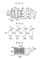
- a device of the invention shown in Figure 4 includes a stylus member 207 having a pair of ends 207a and 207b both of which slightly project from a housing 203 and the first of which is shown in contact with a body surface 217.
- the stylus member 207 has its central flange 207c supported by a helical spring 208 inserted between the upper and lower walls of the housing 203.
- the stylus member 207 is thus resiliently supported by the housing 203.
- a pair of coils 204a and 204b are seated in tandem to surround the stylus member 207 above and below its central flange 207c, respectively.
- a power supply 212 for energizing the coils 204a and 204b comprises an oscillator unit 214 designed to provide across its output terminals 214a and 214b a periodic signal of alternating polarity.
- This periodic signal may, as shown, comprise a succession of alternating rectangular pulses or a positive rectangular half cycle and a negative rectangular half cycle which alternately occur.
- These positive and negative half cycles which develop at the output terminals 214a and 214b are applied to the coils 204a and 204b, respectively, via conductors 223a and conductors 223b.
- a diode 224a and a diode 224b are connected across the conductors 223b, and the conductors 223a, respectively, so as to conduct the positive half cycles and the negative half cycles, respectively and to block the negative half cycles and the positive half cycles, respectively.
- a magnetic field of alternately occuring polarity is thus created by the coils 204a and 204b and applied, concentratedly, to the "tsubo" or key point through the stylus member 207 and its lower end 207a in contact therewith or in proximity thereto.
- An adjustably variable resistor 216 is provided in the power circuit 212 as shown to give a desired intensity of the magnetic field in the range of 300 to 10000 Gauss (surface flux density).
- the oscillator 214 is capable of frequency adjustment sothat, as mentioned before, the fluctuating magnetic field may be of a desired frequency in the range between 1 and 100 Hz.
- the housing 203 is manipulated to bring the tip 207a of the stylus member 207 in engagement with a desired point on the body surface 217.
- the oscillator 214 is activated to energize the coils 204a and 204b. Then, positive half cycles or pulses of the output of the oscillator 214 are passed through the diode 224a, the conductors 223a and the coil 204a, and negative half cycles or pulses thereof are passed through the diode 224b, the conductors 223b and the coil 204b.
- the coils 204a and 204b are thus alternately energized to produce the periodically reversing magnetic field and to apply, through the stylus member 207 which serves as a field concentrator, the periodically reversing magnetic flux to the desired point on the body surface.
- the stylus member 207 is magnetically permeable and may temporarily be magnetized upon each establishment of a magnetic. field. Then, the magnetization of the stylus member 207 may be capable of interacting with the external magnetic field produced by the coil 204a, 204b. For example, when the lower coil 204b is energized to establish the magnetic field directed upwards, the stylus member 207 may be forced downwards.
- the stylus member 207 may be forced upwards. Since the magnetic field occurs alternately, the stylus member 207 may be brought into a vibration of the frequency established at the oscillator 214. In this manner, the stylus tip 207a may repetitively make and break the contact with the.desired point on the body surface 217. Depending on the stroke of this vibration, the external manipulation pressure applied by the housing 203 and exerted on the stylus member 207 via the spring 208 may be adjusted to keep the stylus tip 207a being vibrated in contact with the desired point on the body surface 217. At any event, the vibration of the stylus member 207 brings about an intermittent pressurization and produces recurrent stimulus or impetus on the point on the body surface.
- Stylus members 207 shown in FIGS. 5(a) and 5(b) make use of a permanent magnet whereas those shown in FIGS. 5(c) and 5(d) make use of a nonpermanent magnet material.
- Stylus members 207 of FIGS. 5(a) and 5(c) have tips 207a and 207b shaped to possess a simple round projection.
- Stylus members 207 of FIGS. 5(b-) and 5(d) have tips 207a and 207b shaped to possess three round projections..
- FIG. 4 is, therefore, designed to apply to an affected part a fluctuating magnetic field and flux while subjecting that part to a vibratory stimulus or impetus. In this manner, an intensified stimulating current induction is produced in the blood flow to achieve an enhanced effect of functional recovery and treatment.
- FIG. 6 shows a modification of the embodiment of FIG. 4 wherein a stylus member 307 formed of a magnetically permeable or permanent-magnetic material carries an electromechanical transducer 325 energized by a power supply 326.
- a power supply 326 When the transducer 325 is energized by the power supply 326, a mechanical vibration is produced therein to vibrate the stylus member 307.
- the latter is composed of non-permanent magnet material, coil means is provided and energized by a power supply, both of which are omitted in this FIGURE, to produce a desired fluctuating magnetic field and flux as described before.
- the stylus member 307 When the stylus member 307 is composed of a permanent-magnet material, no such coil and power supply is required to produce the magnetic field and flux which is produced directly by the stylus member 307.
- FIG. 6 the vibration-stimulating tip portion 307a of the stylus member 307 is shown in engagement with a desired portion of the body surface 317 which is slightly deformed thereby under the engagement pressure.
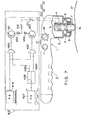
- FIG. 7 shows a magnetic medical treatment device essentially the same as that shown in FIG. 1, and including same parts thereof designated by same reference numerals and a modified power supply circuit, which is designated generally at reference numeral 412, for energizing the coil 4 electromagnetically associated through the core member 5 or directly, with the stylus member 7.
- the power supply 412 comprises a principal oscillator 414 and an additional oscillator 427. The output of the latter is shown fed to a T-type bistable circuit 428 which has a pair of output terminals 428a and 428b.
- a first AND gate 429 is provided to combine the output of the principal oscillator 414 and the first output 428a of the bistable circuit 428.
- a second AND gate 430 is provided to combine the output of the principal oscillator 414 and the second output 428b of the bistable circuit 428.
- the output of the first AND gate 42-9 is fed to a first switching transistor 431 which is connected in series with the coil 4, a first DC source 432, a variable resistor 416 and a switch 10a.
- the output of the second AND gate is fed to a second switching transistor 433 which is connected in series with the coil 4, a second DC source 434, the variable resistor 416 and the switch 10a. The latter represents contacts of the thumb switch 10.
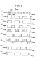
- the principal oscillator 414 provides a stream of electrical pulses as shown in FIG. 8(a), of a frequency ranging between 1 and 100 Hz and having a pulse duration T on.l and a pulse interval ⁇ off.1.
- the additional or control oscillator 427 provides a stream of electrical pulses as shown in FIG. 8(b), of a different frequency and having a duration ron.2 and interval Toff.2 each of which is longer than ⁇ on. 1 and ⁇ off. 1.
- the latter pulses are fed to the T-type bistable circuit 428.
- the first and second output terminals 428a and 428b of the latter alternately provide a pulse in the stream shown in FIG. 8(c) and a pulse in the stream shown in FIG. 8(d).
- the first AND gate 429 provides an output consisting of time-spaced trains of pulses shown in FIG. 8(e) whereas the second gate 430 provides an output consisting of time-spaced trains of pulses shown in FIG. 8(f).
- These alternate trains of signal pulses are furnished to the switching transistors 431 and 433, respectively.
- the transistors 431 and 433 are thus turned on and off accordingly.
- the first transistor 431 is turned on and off to connect and disconnect the first DC source.432 to the coil 4.
- the second transistor 433 is turned on and off to connect and disconnect the second DC source 434 to the coil 4.
- the coil 4 is energized, in a period ⁇ on.2, with each train of power pulses of one polarity and, in a period Toff.2, with each train of power pulses of the opposite polarity, as shown in FIG. 8(g). Since the DC sources 432 and 434 (and the transistors 431 and 433) are connected to the coil 4 to deliver their output currents flowing in opposite directions through the coil 4, the latter produces a pulsed magnetic field of one polarity and the other polarity which alternately occur in a form shown in FIG. 8(g). As a result, the tip 7a of the stylus member 7 is then polarized with time as follows: S-S-S-N-N-S-S-S-N-N-........
- the control oscillator 427 should be adjustable as to the duration ⁇ on.2 and interval ⁇ off.2 of its output pulses.
- the control oscillator 427 may be adjusted to provide a stream of its output pulses which have, in relation to the output pulses ( ⁇ on.1, ⁇ off.1) of the principal oscillator 414, a duration ⁇ on.2 and interval ⁇ off.2 as shown in FIG. 8(h) or FIG. 8(i). It will be seen that in the case of timing of FIG. 8(h), the polarities of the tip 7a of the stylus member 7 are switched as follows: S-N-N-S-N-N-. In the case of timing of FIG.
- the polarities of the tip 7a of the stylus member 7 are switched as follows: S-S-S-S-N-S-S-S-S-N-........
- a knob 35 is provided to allow adjustments of such switching sequence of the magnetic field and is associated with time-constant networks in the control oscillator 427 which determine its output pulse duration T on.2 and interval T off.2.
- FIG. 9 shows another embodiment of the invention which is modified with respect to both the device structure and the.power supply for the coil from those shown earlier.
- the device 501 of FIG. 9 comprises a core member 505 having the coil 504 wound thereon and received in a housing 503. In this embodiment, a stylus member is omitted.
- the housing 503 is securely supported on a flexible, vacuum attachment element 535 in the form of a cup and composed of an elastomeric material.
- the coil 504 is energized by a power supply 512 which basically comprises a DC source 536, a capacitor 537 and a power switch 538.
- the capacitor 537 on one hand is connected in series with the DC source 536, a fixed resistor 539, a variable resistor 540 and a switch 541, and on the other hand is connected in series with the power switch 538, the coil 4 and a variable resistor 542.
- the power switch 538 in the form of a transistor is energized by a signal oscillator 543 and a diode 544 is connected to shunt the coil 504.
- the DC current of the supply 536 flows to charge the capacitor 537 via the resistors 539 and 540 to a predetermined charging level.
- the switch 538 is then turned on to allow the charge on the capacitor 437 to be discharged through the coil 504.
- the oscillator 542 is used to control the timing of turn-on of the switch 538.
- the switch 541 may be controlled by the oscillator 543 as well to precisely control the alternate charging and discharging of the capacitor 537.
- the diode 544 is used to protect the transistor 538 against the opposed polarity component of the discharge current.
- the magnetic field is repetitively produced through the coil 504 and applied to a portion of the body surface beneath the core member 505 positioned by the attachment element 535.
- the pulsed magnetic field should have a duration of 0.1 to 10 milliseconds to yield a better treatment result.
- the variable resistor 542 is provided to allow adjustments of the intensity of the magnetic field in the range between 1000 and 5000 Gauss.
- the core member 505 is composed of pure iron, ferrite, iron-chromium-cobalt alloy, permalloy and sendust.
- the core member may be dimensioned to possess a diameter of 10 mm for practical purposes.
- attachment element 535 supporting the device assembly 501 is advantageous.
- a vaseline or cream may be applied on the inner wall of the element 535 or on a skin on which the element 535 is mounted.
- the element 535 may then be pressed around the skin to be secured thereon.
- Such an attachment element 535 may be applied to substantially any portion on the body surface.
- the device of the invention can be used by and for a patient for a period of 5 to 30 minutes each time and one to five times a day. It has been found that such use of the device of the invention yields a greater curing result than using a permanent magnet or a magnetic field with a fixed intensity continuously all day in accordance with the prior art.
- FIG. 10 shows a modification of the capacitor-type power supply for the coil 504 shown in FIG. 9.
- the modified supply 512' comprises a charging circuit for the capacitor 537 including DC source 536, the fixed charging resistor 539, the variable resistor 540, the switch 541 and a charging inductor 545 which is shown adjustable.
- the discharging circuit for the capacitor 537 comprises a thyristor 546 which is controlledly turned on by a control switching circuit generally designated at 547.
- the control switching circuit 547 comprises a resistor 548 connected across the capacitor 537 to sense its charging voltage.
- a series circuit of a variable resistor 549 and a capacitor 550 is connected across an adjustable tap 548a of the sensing resistor 548 in parallel with a Zener diode 551 to constitute a time-constant network for defining the on-off frequency of the thyristor 546.
- a unijunction transistor 551 connected across a portion of the sensing resistor 548 is controlled by a terminal voltage of the capacitor 550 being applied to its gate electrode 551a and has its drain electrode 551b connected to a control electrode of the thyristor 546.
- the unijunction transistor 551 When the voltage builds up in the capacitor 537 to the level determined by the position of the tap 548a and the rating of the Zenor diode 551, the unijunction transistor 551 sustains a current flow through its drain electrode 551 b . thereby rendering the thyristor 546 conductive. This allows the charge on the capacitor 537 to be discharged through the coil 504.
- the unijunction transistor 551 is cut off after a conductive period determined by the time constant of the network 549, 550.
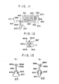
- a fixed core member 661 constituted by laminated E-shaped silicon steel plates has a coil 662 wound thereon.
- the coil 662 is energized by a commercial AC fed through leads 663 to produce magnetic fluxes through the fixed core member 661.
- a movable iron plate 664 is carried by an L-shaped member 665 whose one end is attached to one end of the fixed core member 661 by means of screws 666, so that the plate 664 is spacedly juxtaposed with the core member 661 and with the coil 662 energized, the member 665 is vibrated.
- the member 665 terminates with a chuck 667 on which a shank 668, 668' carrying a device of the invention 670, 670' is detachably mounted.
- the chuck 667 comprises a U-shaped clamping element 667a having a space 667b into which the mounting end 668a of the shank 668 is inserted.
- This end includes a key element 668b adapted to mate with a positioning depression 667c in the space 667b.
- a bolt 667d is inserted through 'openings (not shown) in the clamping element 667a and through an opening 668c formed in the mounting end 668a of the shank 668, and a butterfly nut 667e is then threaded with the.bolt 667d to firmly secure the shank 668 supporting the device 670 to the vibratile member 665.
- the device 670, 670' as shown in FIG. 13 comprises a stylus member 607, 607' having a coil 604, 604',wound thereon, the coil being energized by an electric current of fluctuating intensity (e.g. AC) to produce a fluctuating (e.g. AC) magnetic field and flux which is applied through the stylus member 607, 607' to a selected surface zone of the patient's body surface as has been described.
- an electric current of fluctuating intensity e.g. AC
- fluctuating e.g. AC
- the device 670, 670' may have a stylus member 607, 607' which as shown in FIGS. 13(A) and 13(B) is formed with a desired shape along its tip area adapted to contact with the body surface.
- the stylus member 607 shown in FIG. 13(A) is preferred to exert a rubbing or kneading effect on the body surface whereas the stylus member 607' shown in FIG. 13(B) is preferred to exert a tapping or stroking effect on the body surface.
- the device 670 of FIG. 13(A) should be secured via the chuck 667 to the vibratile member 665 to extend generally coaxial therewith so as to be vibrated (i.e. swingingly vibrated) as indicated by arrows 671.
- the device 670' of FIG. 13(B) should be secured via the chuck 667 to the vibratile member 665 to extend generally perpendicular thereto so as to be vibrated (i.e. reciprocatingly vibrated) as indicated by arrows 671'.
- the vibrating unit, 661, 662, 664, 665 is shown accommodated in a casing 672 provided with a manual switch -673 for switching on and off the energization of the coil 662 (in the vibrator) and of the coil 604 (for magnetic treatment).
- the stylus member 607, 607' having the coil 604, 604' wound thereon may be contained in a housing 603, 603' so that its end portion is projected therefrom for engagement with a preselected surface zone of the body surface of a patient as has been described.
- magic tape is intended to imply a tape which becomes adherent to an adjacent such tape simply by bringing the two tapes into contact or close proximity with one another.
- Such tapes may utilise magnetic attraction effects, or the self- attachment properties of tapes comprising respectively arrays of hooks and arrays of loops (such as tapes available commercially under the trade name 'Velcro'), for example.
Applications Claiming Priority (10)
| Application Number | Priority Date | Filing Date | Title |
|---|---|---|---|
| JP52851/80 | 1980-04-23 | ||
| JP5285180A JPS56151063A (en) | 1980-04-23 | 1980-04-23 | Magnetic treating appliance |
| JP6371780A JPS56158665A (en) | 1980-05-13 | 1980-05-13 | Magnetic therapeutic appliance |
| JP63717/80 | 1980-05-13 | ||
| JP71483/80 | 1980-05-30 | ||
| JP7148380A JPS56168754A (en) | 1980-05-30 | 1980-05-30 | Magnetic treatment instrument |
| JP97574/80 | 1980-07-18 | ||
| JP9757480A JPS5722770A (en) | 1980-07-18 | 1980-07-18 | Magnetic treating instrument |
| JP10572/80 | 1980-07-28 | ||
| JP10567280U JPS6039007Y2 (ja) | 1980-07-28 | 1980-07-28 | 磁気按摩器 |
Publications (2)
| Publication Number | Publication Date |
|---|---|
| EP0039206A1 true EP0039206A1 (de) | 1981-11-04 |
| EP0039206B1 EP0039206B1 (de) | 1984-10-10 |
Family
ID=27523041
Family Applications (1)
| Application Number | Title | Priority Date | Filing Date |
|---|---|---|---|
| EP81301791A Expired EP0039206B1 (de) | 1980-04-23 | 1981-04-23 | Gerät zur magnetischen Behandlung |
Country Status (3)
| Country | Link |
|---|---|
| US (1) | US5030196A (de) |
| EP (1) | EP0039206B1 (de) |
| DE (1) | DE3166555D1 (de) |
Cited By (11)
| Publication number | Priority date | Publication date | Assignee | Title |
|---|---|---|---|---|
| EP0048451A1 (de) * | 1980-09-24 | 1982-03-31 | 121873 Canada Inc. | Elektromagnetisches therapeutisches System und Verfahren |
| EP0099734A1 (de) * | 1982-07-20 | 1984-02-01 | Tesla, Koncernovy Podnik | Magnetotherapeutische Impulseinrichtung |
| DE3327920A1 (de) * | 1982-09-21 | 1984-10-04 | Ken Hashimoto | Elektromagnetische therapeutische vorrichtung |
| FR2546758A1 (fr) * | 1983-06-02 | 1984-12-07 | Cadossi Ruggero | Dispositif de traitement de tissus et/ou cellules vivants au moyen de champs electromagnetiques pulses |
| GB2156608A (en) * | 1984-02-16 | 1985-10-09 | Hayashibara Ken | Apparatus for generating alternating magnetic flux |
| US4551781A (en) * | 1983-08-03 | 1985-11-05 | Chris G. Nicholson | Control circuit for magnetic probe |
| AT382785B (de) * | 1982-10-18 | 1987-04-10 | Rudolf Himmelsbach | Einrichtung zur beeinflussung von biofrequenzen |
| EP0223354A2 (de) * | 1985-09-11 | 1987-05-27 | Elizabeth A. Rauscher | Vorrichtung zur Modulation von Gehirnsignalen durch ein äusserliches Magnetfeld zur Reduktion von Schmerz |
| GB2360213A (en) * | 1999-11-11 | 2001-09-19 | Magstim Co Ltd | Neuro-muscular magnetic stimulation coil and apparatus |
| EP0906136B1 (de) * | 1994-11-28 | 2004-06-30 | Neotonus, Inc. | Magnetischer stimulator zur reizung peripherer nerven |
| FR2855060A1 (fr) | 2003-05-21 | 2004-11-26 | Chapellier Pierre Jean Mari Le | Appareil de soins medicaux anti-douleurs utilisant un magnetisme pulse qualifie |
Families Citing this family (110)
| Publication number | Priority date | Publication date | Assignee | Title |
|---|---|---|---|---|
| US5116304A (en) * | 1987-01-28 | 1992-05-26 | Cadwell Industries, Inc. | Magnetic stimulator with skullcap-shaped coil |
| FR2652928B1 (fr) | 1989-10-05 | 1994-07-29 | Diadix Sa | Systeme interactif d'intervention locale a l'interieur d'une zone d'une structure non homogene. |
| DE4132428C2 (de) * | 1991-09-28 | 1999-03-11 | Anton Quell | Magneto-Therapiegerät |
| CA2142338C (en) | 1992-08-14 | 1999-11-30 | John Stuart Bladen | Position location system |
| AU661789B2 (en) * | 1992-08-26 | 1995-08-03 | Larkace Pty Ltd | Magnetic field induction multi-pulse therapy |
| US5654864A (en) * | 1994-07-25 | 1997-08-05 | University Of Virginia Patent Foundation | Control method for magnetic stereotaxis system |
| US5592939A (en) | 1995-06-14 | 1997-01-14 | Martinelli; Michael A. | Method and system for navigating a catheter probe |
| US6226548B1 (en) | 1997-09-24 | 2001-05-01 | Surgical Navigation Technologies, Inc. | Percutaneous registration apparatus and method for use in computer-assisted surgical navigation |
| US6083149A (en) * | 1997-10-22 | 2000-07-04 | Emf Therapeutics, Inc. | Magnetic field device and method for inhibiting angiogenesis and retarding growth rates of tumors in mammals |
| US6021343A (en) | 1997-11-20 | 2000-02-01 | Surgical Navigation Technologies | Image guided awl/tap/screwdriver |
| US6348058B1 (en) | 1997-12-12 | 2002-02-19 | Surgical Navigation Technologies, Inc. | Image guided spinal surgery guide, system, and method for use thereof |
| US6477400B1 (en) | 1998-08-20 | 2002-11-05 | Sofamor Danek Holdings, Inc. | Fluoroscopic image guided orthopaedic surgery system with intraoperative registration |
| US6155966A (en) * | 1998-11-17 | 2000-12-05 | Parker; Lloyd S. | Apparatus and method for toning tissue with a focused, coherent electromagnetic field |
| US6149577A (en) * | 1999-03-18 | 2000-11-21 | Emf Therapeutics, Inc. | Apparatus and method for creating a substantially contained, finite magnetic field useful for relieving the symptoms pain and discomfort associated with degenerative diseases and disorders in mammals |
| US6470207B1 (en) | 1999-03-23 | 2002-10-22 | Surgical Navigation Technologies, Inc. | Navigational guidance via computer-assisted fluoroscopic imaging |
| US6491699B1 (en) | 1999-04-20 | 2002-12-10 | Surgical Navigation Technologies, Inc. | Instrument guidance method and system for image guided surgery |
| US6493573B1 (en) | 1999-10-28 | 2002-12-10 | Winchester Development Associates | Method and system for navigating a catheter probe in the presence of field-influencing objects |
| US6747539B1 (en) | 1999-10-28 | 2004-06-08 | Michael A. Martinelli | Patient-shielding and coil system |
| US6381485B1 (en) | 1999-10-28 | 2002-04-30 | Surgical Navigation Technologies, Inc. | Registration of human anatomy integrated for electromagnetic localization |
| AU1104901A (en) * | 1999-10-28 | 2001-05-08 | Enterprise Medical Technology, Inc. | Patient-shielding and coil system |
| US6474341B1 (en) | 1999-10-28 | 2002-11-05 | Surgical Navigation Technologies, Inc. | Surgical communication and power system |
| US8239001B2 (en) | 2003-10-17 | 2012-08-07 | Medtronic Navigation, Inc. | Method and apparatus for surgical navigation |
| US11331150B2 (en) | 1999-10-28 | 2022-05-17 | Medtronic Navigation, Inc. | Method and apparatus for surgical navigation |
| US6379302B1 (en) | 1999-10-28 | 2002-04-30 | Surgical Navigation Technologies Inc. | Navigation information overlay onto ultrasound imagery |
| US6499488B1 (en) | 1999-10-28 | 2002-12-31 | Winchester Development Associates | Surgical sensor |
| US7366562B2 (en) | 2003-10-17 | 2008-04-29 | Medtronic Navigation, Inc. | Method and apparatus for surgical navigation |
| US8644907B2 (en) | 1999-10-28 | 2014-02-04 | Medtronic Navigaton, Inc. | Method and apparatus for surgical navigation |
| US6275996B1 (en) | 2000-01-28 | 2001-08-21 | Acushnet Company | Articles with removable elements |
| WO2001064124A1 (en) | 2000-03-01 | 2001-09-07 | Surgical Navigation Technologies, Inc. | Multiple cannula image guided tool for image guided procedures |
| US6338347B1 (en) * | 2000-04-04 | 2002-01-15 | Yun-Yin Chung | Blood circulation stimulator |
| US6535756B1 (en) | 2000-04-07 | 2003-03-18 | Surgical Navigation Technologies, Inc. | Trajectory storage apparatus and method for surgical navigation system |
| US7085400B1 (en) | 2000-06-14 | 2006-08-01 | Surgical Navigation Technologies, Inc. | System and method for image based sensor calibration |
| WO2002030511A2 (de) * | 2000-10-09 | 2002-04-18 | Medical Magnetics, S.A. | Vorrichtung zur behandlung von fettleibigkeit, cellulitis etc. |
| US6636757B1 (en) | 2001-06-04 | 2003-10-21 | Surgical Navigation Technologies, Inc. | Method and apparatus for electromagnetic navigation of a surgical probe near a metal object |
| US6947786B2 (en) | 2002-02-28 | 2005-09-20 | Surgical Navigation Technologies, Inc. | Method and apparatus for perspective inversion |
| US6990368B2 (en) | 2002-04-04 | 2006-01-24 | Surgical Navigation Technologies, Inc. | Method and apparatus for virtual digital subtraction angiography |
| US7998062B2 (en) | 2004-03-29 | 2011-08-16 | Superdimension, Ltd. | Endoscope structures and techniques for navigating to a target in branched structure |
| US6892090B2 (en) | 2002-08-19 | 2005-05-10 | Surgical Navigation Technologies, Inc. | Method and apparatus for virtual endoscopy |
| US6899667B2 (en) * | 2002-10-21 | 2005-05-31 | Paul F. Becker | Method and apparatus for the treatment of physical and mental disorders with low frequency, low flux density magnetic fields |
| US7819794B2 (en) * | 2002-10-21 | 2010-10-26 | Becker Paul F | Method and apparatus for the treatment of physical and mental disorders with low frequency, low flux density magnetic fields |
| US7599730B2 (en) | 2002-11-19 | 2009-10-06 | Medtronic Navigation, Inc. | Navigation system for cardiac therapies |
| US7697972B2 (en) | 2002-11-19 | 2010-04-13 | Medtronic Navigation, Inc. | Navigation system for cardiac therapies |
| US7542791B2 (en) | 2003-01-30 | 2009-06-02 | Medtronic Navigation, Inc. | Method and apparatus for preplanning a surgical procedure |
| US7660623B2 (en) | 2003-01-30 | 2010-02-09 | Medtronic Navigation, Inc. | Six degree of freedom alignment display for medical procedures |
| US7313430B2 (en) | 2003-08-28 | 2007-12-25 | Medtronic Navigation, Inc. | Method and apparatus for performing stereotactic surgery |
| EP2316328B1 (de) | 2003-09-15 | 2012-05-09 | Super Dimension Ltd. | Umhüllungsvorrichtung zur Fixierung von Bronchoskopen |
| EP2113189B1 (de) | 2003-09-15 | 2013-09-04 | Covidien LP | System aus Zubehör zur Verwendung mit Bronchoskopen |
| JP4322080B2 (ja) * | 2003-09-22 | 2009-08-26 | タカタ株式会社 | エアバッグ装置 |
| US7835778B2 (en) | 2003-10-16 | 2010-11-16 | Medtronic Navigation, Inc. | Method and apparatus for surgical navigation of a multiple piece construct for implantation |
| US7840253B2 (en) | 2003-10-17 | 2010-11-23 | Medtronic Navigation, Inc. | Method and apparatus for surgical navigation |
| US8764725B2 (en) | 2004-02-09 | 2014-07-01 | Covidien Lp | Directional anchoring mechanism, method and applications thereof |
| US7567834B2 (en) | 2004-05-03 | 2009-07-28 | Medtronic Navigation, Inc. | Method and apparatus for implantation between two vertebral bodies |
| US20060122453A1 (en) * | 2004-12-02 | 2006-06-08 | Nikolay Alekseyenko | Therapeutic device for local area stimulation |
| US7835784B2 (en) | 2005-09-21 | 2010-11-16 | Medtronic Navigation, Inc. | Method and apparatus for positioning a reference frame |
| US20070078292A1 (en) * | 2005-10-05 | 2007-04-05 | Electromagnetic Resources, Inc. | Electromagnetic fields for systemic effect in therapy |
| US9168102B2 (en) | 2006-01-18 | 2015-10-27 | Medtronic Navigation, Inc. | Method and apparatus for providing a container to a sterile environment |
| US8112292B2 (en) | 2006-04-21 | 2012-02-07 | Medtronic Navigation, Inc. | Method and apparatus for optimizing a therapy |
| US8545378B2 (en) | 2006-06-15 | 2013-10-01 | The Trustees Of Columbia University In The City Of New York | Systems and methods for inducing electric field pulses in a body organ |
| US7753836B2 (en) * | 2006-06-15 | 2010-07-13 | The Trustees Of Columbia University In The City Of New York | Systems and methods for inducing electric field pulses in a body organ |
| US8049489B2 (en) | 2006-07-26 | 2011-11-01 | Cardiac Pacemakers, Inc. | Systems and methods for sensing external magnetic fields in implantable medical devices |
| US8660635B2 (en) | 2006-09-29 | 2014-02-25 | Medtronic, Inc. | Method and apparatus for optimizing a computer assisted surgical procedure |
| US8069823B2 (en) * | 2007-01-03 | 2011-12-06 | Radio Systems Corporation | Vibration stimulus delivery device |
| US20090081752A1 (en) * | 2007-09-24 | 2009-03-26 | Dennis Robert G | Bioreactor, kit and method of using same |
| US20090082610A1 (en) * | 2007-09-24 | 2009-03-26 | Wolf David A | Osteo or tissue healing device, kit and method of using the same |
| US8905920B2 (en) | 2007-09-27 | 2014-12-09 | Covidien Lp | Bronchoscope adapter and method |
| JPWO2009119236A1 (ja) * | 2008-03-26 | 2011-07-21 | テルモ株式会社 | 治療装置 |
| US9575140B2 (en) | 2008-04-03 | 2017-02-21 | Covidien Lp | Magnetic interference detection system and method |
| EP2297673B1 (de) | 2008-06-03 | 2020-04-22 | Covidien LP | Registrationsverfahren auf merkmalbasis |
| US8218847B2 (en) | 2008-06-06 | 2012-07-10 | Superdimension, Ltd. | Hybrid registration method |
| US8932207B2 (en) | 2008-07-10 | 2015-01-13 | Covidien Lp | Integrated multi-functional endoscopic tool |
| US8165658B2 (en) | 2008-09-26 | 2012-04-24 | Medtronic, Inc. | Method and apparatus for positioning a guide relative to a base |
| US8175681B2 (en) | 2008-12-16 | 2012-05-08 | Medtronic Navigation Inc. | Combination of electromagnetic and electropotential localization |
| US8611984B2 (en) | 2009-04-08 | 2013-12-17 | Covidien Lp | Locatable catheter |
| US8569050B1 (en) | 2009-05-04 | 2013-10-29 | John D. Ericsson | Enclosed bioreactor system and methods associated therewith |
| EP2907540A1 (de) | 2009-05-19 | 2015-08-19 | The Trustees of Columbia University in the City of New York | Magnetisches Stimulationssystem |
| US8494613B2 (en) | 2009-08-31 | 2013-07-23 | Medtronic, Inc. | Combination localization system |
| US8494614B2 (en) | 2009-08-31 | 2013-07-23 | Regents Of The University Of Minnesota | Combination localization system |
| US10582834B2 (en) | 2010-06-15 | 2020-03-10 | Covidien Lp | Locatable expandable working channel and method |
| FR2962047B1 (fr) * | 2010-07-05 | 2013-11-29 | Oreal | Dispositif de traitement magnetoelectrique |
| ITRE20120010A1 (it) * | 2012-02-16 | 2013-08-17 | Mantis S R L | Metodo e circuito per la generazione di un campo magnetico pulsato per un dispositivo elettromedicale |
| US20130303827A1 (en) * | 2012-05-14 | 2013-11-14 | Yvonne Ya-Wen Feng | Magnetic Devices And Uses Thereof For Treatment Of Disease |
| GB201222255D0 (en) * | 2012-12-11 | 2013-01-23 | Ucl Business Plc | Muscle conditioning device |
| US9724535B1 (en) * | 2013-02-19 | 2017-08-08 | Blugreen Technologies, Inc. | Low frequency magnetic pulse variable resonator for actively influencing the interaction and intercommunication at the cellular level for biological organisms and molecular level of matter |
| CA3107228A1 (en) * | 2013-03-15 | 2014-09-18 | Implantica Patent Ltd. | Operable implant comprising an electrical motor and a gear system |
| JP2016187364A (ja) * | 2013-09-20 | 2016-11-04 | 第一高周波工業株式会社 | 磁束照射装置 |
| WO2015063534A1 (en) * | 2013-10-30 | 2015-05-07 | Mohamed Hossam Abdel Salam El Sayed | Uni-polar pulsed electromagnetic medical apparatus and methods of use |
| CN203932555U (zh) * | 2014-05-05 | 2014-11-05 | 中兴通讯股份有限公司 | 一种吸附器及连接器 |
| US10952593B2 (en) | 2014-06-10 | 2021-03-23 | Covidien Lp | Bronchoscope adapter |
| US10426555B2 (en) | 2015-06-03 | 2019-10-01 | Covidien Lp | Medical instrument with sensor for use in a system and method for electromagnetic navigation |
| US9962134B2 (en) | 2015-10-28 | 2018-05-08 | Medtronic Navigation, Inc. | Apparatus and method for maintaining image quality while minimizing X-ray dosage of a patient |
| US11247039B2 (en) | 2016-05-03 | 2022-02-15 | Btl Healthcare Technologies A.S. | Device including RF source of energy and vacuum system |
| US10478254B2 (en) | 2016-05-16 | 2019-11-19 | Covidien Lp | System and method to access lung tissue |
| US10583287B2 (en) | 2016-05-23 | 2020-03-10 | Btl Medical Technologies S.R.O. | Systems and methods for tissue treatment |
| US10556122B1 (en) | 2016-07-01 | 2020-02-11 | Btl Medical Technologies S.R.O. | Aesthetic method of biological structure treatment by magnetic field |
| US10638952B2 (en) | 2016-10-28 | 2020-05-05 | Covidien Lp | Methods, systems, and computer-readable media for calibrating an electromagnetic navigation system |
| US10517505B2 (en) | 2016-10-28 | 2019-12-31 | Covidien Lp | Systems, methods, and computer-readable media for optimizing an electromagnetic navigation system |
| US10446931B2 (en) | 2016-10-28 | 2019-10-15 | Covidien Lp | Electromagnetic navigation antenna assembly and electromagnetic navigation system including the same |
| US10751126B2 (en) | 2016-10-28 | 2020-08-25 | Covidien Lp | System and method for generating a map for electromagnetic navigation |
| US10792106B2 (en) | 2016-10-28 | 2020-10-06 | Covidien Lp | System for calibrating an electromagnetic navigation system |
| US10418705B2 (en) | 2016-10-28 | 2019-09-17 | Covidien Lp | Electromagnetic navigation antenna assembly and electromagnetic navigation system including the same |
| US10615500B2 (en) | 2016-10-28 | 2020-04-07 | Covidien Lp | System and method for designing electromagnetic navigation antenna assemblies |
| US10722311B2 (en) | 2016-10-28 | 2020-07-28 | Covidien Lp | System and method for identifying a location and/or an orientation of an electromagnetic sensor based on a map |
| KR102587035B1 (ko) * | 2017-02-19 | 2023-10-10 | 솔리톤, 인코포레이티드 | 생물학적 매체 내의 선택적 레이저 유도 광학 파괴 |
| EP3616749A1 (de) * | 2017-04-24 | 2020-03-04 | Cellpower Co., Ltd. | Magnetische therapievorrichtung |
| IL253677B2 (en) * | 2017-07-26 | 2023-06-01 | Epitech Mag Ltd | A magnetic device for the treatment of living tissues |
| US11219489B2 (en) | 2017-10-31 | 2022-01-11 | Covidien Lp | Devices and systems for providing sensors in parallel with medical tools |
| US10967194B2 (en) | 2018-05-02 | 2021-04-06 | Shealy-Sorin Wellness, Llc | Pulsed electromagnetic field device and methods of use |
| MX2022013485A (es) | 2020-05-04 | 2022-11-30 | Btl Healthcare Tech A S | Dispositivo y metodo para el tratamiento sin atencion del paciente. |
| US11878167B2 (en) | 2020-05-04 | 2024-01-23 | Btl Healthcare Technologies A.S. | Device and method for unattended treatment of a patient |
| US11896816B2 (en) | 2021-11-03 | 2024-02-13 | Btl Healthcare Technologies A.S. | Device and method for unattended treatment of a patient |
Citations (11)
| Publication number | Priority date | Publication date | Assignee | Title |
|---|---|---|---|---|
| GB1058319A (en) * | 1964-08-18 | 1967-02-08 | Ulf Tore Walden | Improvements in or relating to therapeutic apparatus |
| US3337776A (en) * | 1964-06-10 | 1967-08-22 | Guidoni | Biomedical apparatus for generating controllable magnetic fields |
| BE732425A (de) * | 1968-05-02 | 1969-10-16 | ||
| DE2553197A1 (de) * | 1975-11-27 | 1977-06-08 | Michael Buschky | Impulsfeldgenerator |
| DE2603934A1 (de) * | 1975-11-27 | 1977-08-04 | Michael Buschky | Impulsfeldgenerator |
| DE2632501A1 (de) * | 1976-07-20 | 1978-01-26 | Ludwig Wolfgang Dr Rer Nat | Magnetimpulsgeraet und seine medizinische anwendung |
| FR2369850A1 (fr) * | 1976-11-03 | 1978-06-02 | Fragnet Jean | Appareil d'emission magnetique et electromagnetique a usage medical |
| DE2707574A1 (de) * | 1977-02-22 | 1978-08-24 | Goedde Geb Elsaesser Anna | Vorrichtung zur beeinflussung biologischer ablaeufe in einem lebenden koerper mit hilfe eines von einer spulenanordnung erzeugten magnetfeldes |
| US4112923A (en) * | 1976-08-24 | 1978-09-12 | Tomecek Jerry J | Antonomic transcutaneous affect device |
| FR2413083A1 (fr) * | 1978-01-02 | 1979-07-27 | Kief Horst | Appareil d'acuponcture |
| FR2445151A1 (fr) * | 1978-12-27 | 1980-07-25 | Skovajsa Joseph | Traitement localise d'un patient a l'aide d'un champ magnetique |
Family Cites Families (7)
| Publication number | Priority date | Publication date | Assignee | Title |
|---|---|---|---|---|
| US3658051A (en) * | 1967-11-13 | 1972-04-25 | Kenneth Sheldon Maclean | Method of treating living things using high intensity pulsed magnetic field |
| US3911930A (en) * | 1974-03-01 | 1975-10-14 | Stimulation Tech | Method and structure of preventing and treating ileus, and reducing acute pain by electrical pulse stimulation |
| FR2342502A1 (fr) * | 1976-02-24 | 1977-09-23 | Sedat | Appareil pour la mesure de la resistance electrique superficielle locale d'un organisme |
| US4105017A (en) * | 1976-11-17 | 1978-08-08 | Electro-Biology, Inc. | Modification of the growth repair and maintenance behavior of living tissue and cells by a specific and selective change in electrical environment |
| SU688192A1 (ru) * | 1977-05-17 | 1979-09-30 | Пермский государственный медицинский институт | Способ воздействи на биологически активные точки |
| DE2736345C2 (de) * | 1977-08-12 | 1983-01-05 | Heinrich Dr.-Ing. 3300 Braunschweig Peesel | Gerät zur Erzeugung eines elektrischen Behandlungsstromes im Zellgewebe eines Patienten |
| US4233965A (en) * | 1978-01-16 | 1980-11-18 | Cas Products, Inc. | Method and apparatus for the therapeutic treatment of living tissue |
-
1981
- 1981-04-23 DE DE8181301791T patent/DE3166555D1/de not_active Expired
- 1981-04-23 EP EP81301791A patent/EP0039206B1/de not_active Expired
-
1983
- 1983-07-15 US US06/514,356 patent/US5030196A/en not_active Expired - Fee Related
Patent Citations (11)
| Publication number | Priority date | Publication date | Assignee | Title |
|---|---|---|---|---|
| US3337776A (en) * | 1964-06-10 | 1967-08-22 | Guidoni | Biomedical apparatus for generating controllable magnetic fields |
| GB1058319A (en) * | 1964-08-18 | 1967-02-08 | Ulf Tore Walden | Improvements in or relating to therapeutic apparatus |
| BE732425A (de) * | 1968-05-02 | 1969-10-16 | ||
| DE2553197A1 (de) * | 1975-11-27 | 1977-06-08 | Michael Buschky | Impulsfeldgenerator |
| DE2603934A1 (de) * | 1975-11-27 | 1977-08-04 | Michael Buschky | Impulsfeldgenerator |
| DE2632501A1 (de) * | 1976-07-20 | 1978-01-26 | Ludwig Wolfgang Dr Rer Nat | Magnetimpulsgeraet und seine medizinische anwendung |
| US4112923A (en) * | 1976-08-24 | 1978-09-12 | Tomecek Jerry J | Antonomic transcutaneous affect device |
| FR2369850A1 (fr) * | 1976-11-03 | 1978-06-02 | Fragnet Jean | Appareil d'emission magnetique et electromagnetique a usage medical |
| DE2707574A1 (de) * | 1977-02-22 | 1978-08-24 | Goedde Geb Elsaesser Anna | Vorrichtung zur beeinflussung biologischer ablaeufe in einem lebenden koerper mit hilfe eines von einer spulenanordnung erzeugten magnetfeldes |
| FR2413083A1 (fr) * | 1978-01-02 | 1979-07-27 | Kief Horst | Appareil d'acuponcture |
| FR2445151A1 (fr) * | 1978-12-27 | 1980-07-25 | Skovajsa Joseph | Traitement localise d'un patient a l'aide d'un champ magnetique |
Cited By (15)
| Publication number | Priority date | Publication date | Assignee | Title |
|---|---|---|---|---|
| EP0048451A1 (de) * | 1980-09-24 | 1982-03-31 | 121873 Canada Inc. | Elektromagnetisches therapeutisches System und Verfahren |
| EP0099734A1 (de) * | 1982-07-20 | 1984-02-01 | Tesla, Koncernovy Podnik | Magnetotherapeutische Impulseinrichtung |
| DE3327920A1 (de) * | 1982-09-21 | 1984-10-04 | Ken Hashimoto | Elektromagnetische therapeutische vorrichtung |
| GB2143131A (en) * | 1982-09-21 | 1985-02-06 | Ken Hashimoto | Therapeutic devices |
| AT382785B (de) * | 1982-10-18 | 1987-04-10 | Rudolf Himmelsbach | Einrichtung zur beeinflussung von biofrequenzen |
| FR2546758A1 (fr) * | 1983-06-02 | 1984-12-07 | Cadossi Ruggero | Dispositif de traitement de tissus et/ou cellules vivants au moyen de champs electromagnetiques pulses |
| US4551781A (en) * | 1983-08-03 | 1985-11-05 | Chris G. Nicholson | Control circuit for magnetic probe |
| GB2156608A (en) * | 1984-02-16 | 1985-10-09 | Hayashibara Ken | Apparatus for generating alternating magnetic flux |
| EP0223354A2 (de) * | 1985-09-11 | 1987-05-27 | Elizabeth A. Rauscher | Vorrichtung zur Modulation von Gehirnsignalen durch ein äusserliches Magnetfeld zur Reduktion von Schmerz |
| EP0223354A3 (en) * | 1985-09-11 | 1989-07-26 | Elizabeth A. Rauscher | Non-invasive method and apparatus for modulating brain signals through an external magnetic field to pace the heart and reduce pain |
| EP0906136B1 (de) * | 1994-11-28 | 2004-06-30 | Neotonus, Inc. | Magnetischer stimulator zur reizung peripherer nerven |
| GB2360213A (en) * | 1999-11-11 | 2001-09-19 | Magstim Co Ltd | Neuro-muscular magnetic stimulation coil and apparatus |
| GB2360213B (en) * | 1999-11-11 | 2002-07-24 | Magstim Co Ltd | Stimulators and stimulating coils for magnetically stimulating neuro-muscular tissue |
| US6663556B2 (en) | 1999-11-11 | 2003-12-16 | The Magstim Company Limited | Stimulators and stimulating coils for magnetically stimulating neuro-muscular tissue |
| FR2855060A1 (fr) | 2003-05-21 | 2004-11-26 | Chapellier Pierre Jean Mari Le | Appareil de soins medicaux anti-douleurs utilisant un magnetisme pulse qualifie |
Also Published As
| Publication number | Publication date |
|---|---|
| EP0039206B1 (de) | 1984-10-10 |
| DE3166555D1 (en) | 1984-11-15 |
| US5030196A (en) | 1991-07-09 |
Similar Documents
| Publication | Publication Date | Title |
|---|---|---|
| EP0039206A1 (de) | Gerät zur magnetischen Behandlung | |
| US6186941B1 (en) | Magnetic coil for pulsed electromagnetic field | |
| US4846178A (en) | Electric field therapeutic apparatus | |
| ATE297786T1 (de) | Pemf-vorrichtung zur behandlung der osteoporose und zur stimulation des wachstums von geweben | |
| EP0309093A1 (de) | Niederfrequenz-Elektrotherapiegerät | |
| KR950014481B1 (ko) | 전기자극 장치 | |
| CA2127225C (en) | Magnetic field induction multi-pulse therapy | |
| US7343203B2 (en) | Apparatus for electrotherapy | |
| JPH0229340B2 (de) | ||
| JPS621736B2 (de) | ||
| EP1320404A1 (de) | Akupunkturpunktstimulation zur heilung von verschiedenen krankheiten | |
| WO2004067084A1 (en) | Electrotherapy apparatus using low and intermediate frequencies | |
| CA2090286C (en) | Device for generating an electrical voltage of predetermined waveform, iontophoresis apparatus for transdermally administering medicinal products and electrical stimulation apparatus, which apparatuses are equipped with such a device | |
| US6450940B1 (en) | Magnetic stimulation device | |
| JPH0134630B2 (de) | ||
| FI96385C (fi) | Laite imunesteiden salpautumien ja vastaavien hoitamiseksi | |
| JPS61500594A (ja) | 非侵入的治療方法及びこの方法を実施するための回路 | |
| US3731111A (en) | Pulse generator | |
| JPH0339704B2 (de) | ||
| JPS6157031B2 (de) | ||
| JPS629880Y2 (de) | ||
| SU1217412A1 (ru) | Устройство дл регул ции уровн нервно-психической активности и работоспособности человека | |
| RU2051706C1 (ru) | Устройство для магнитотерапии | |
| RU4480U1 (ru) | Устройство для рефлексотерапии | |
| RU2152812C2 (ru) | Аппарат для воздействия импульсным магнитным полем на организм человека |
Legal Events
| Date | Code | Title | Description |
|---|---|---|---|
| PUAI | Public reference made under article 153(3) epc to a published international application that has entered the european phase |
Free format text: ORIGINAL CODE: 0009012 |
|
| AK | Designated contracting states |
Designated state(s): DE FR GB IT |
|
| 17P | Request for examination filed |
Effective date: 19811006 |
|
| ITCL | It: translation for ep claims filed |
Representative=s name: FIAMMENGHI FIAMMENGHI RACHELI |
|
| DET | De: translation of patent claims | ||
| ITF | It: translation for a ep patent filed |
Owner name: FIAMMENGHI - DOMENIGHETTI |
|
| GRAA | (expected) grant |
Free format text: ORIGINAL CODE: 0009210 |
|
| AK | Designated contracting states |
Designated state(s): DE FR GB IT |
|
| REF | Corresponds to: |
Ref document number: 3166555 Country of ref document: DE Date of ref document: 19841115 |
|
| ET | Fr: translation filed | ||
| PLBE | No opposition filed within time limit |
Free format text: ORIGINAL CODE: 0009261 |
|
| STAA | Information on the status of an ep patent application or granted ep patent |
Free format text: STATUS: NO OPPOSITION FILED WITHIN TIME LIMIT |
|
| 26N | No opposition filed | ||
| PGFP | Annual fee paid to national office [announced via postgrant information from national office to epo] |
Ref country code: GB Payment date: 19890331 Year of fee payment: 9 |
|
| PGFP | Annual fee paid to national office [announced via postgrant information from national office to epo] |
Ref country code: FR Payment date: 19890428 Year of fee payment: 9 |
|
| PGFP | Annual fee paid to national office [announced via postgrant information from national office to epo] |
Ref country code: DE Payment date: 19890620 Year of fee payment: 9 |
|
| PG25 | Lapsed in a contracting state [announced via postgrant information from national office to epo] |
Ref country code: GB Effective date: 19900423 |
|
| GBPC | Gb: european patent ceased through non-payment of renewal fee | ||
| PG25 | Lapsed in a contracting state [announced via postgrant information from national office to epo] |
Ref country code: FR Effective date: 19901228 |
|
| PG25 | Lapsed in a contracting state [announced via postgrant information from national office to epo] |
Ref country code: DE Effective date: 19910101 |
|
| REG | Reference to a national code |
Ref country code: FR Ref legal event code: ST |