EP0048451A1 - Elektromagnetisches therapeutisches System und Verfahren - Google Patents
Elektromagnetisches therapeutisches System und Verfahren Download PDFInfo
- Publication number
- EP0048451A1 EP0048451A1 EP81107360A EP81107360A EP0048451A1 EP 0048451 A1 EP0048451 A1 EP 0048451A1 EP 81107360 A EP81107360 A EP 81107360A EP 81107360 A EP81107360 A EP 81107360A EP 0048451 A1 EP0048451 A1 EP 0048451A1
- Authority
- EP
- European Patent Office
- Prior art keywords
- coil
- treatment
- circuit
- magnetic field
- field
- Prior art date
- Legal status (The legal status is an assumption and is not a legal conclusion. Google has not performed a legal analysis and makes no representation as to the accuracy of the status listed.)
- Withdrawn
Links
Images


Classifications
-
- A—HUMAN NECESSITIES
- A61—MEDICAL OR VETERINARY SCIENCE; HYGIENE
- A61N—ELECTROTHERAPY; MAGNETOTHERAPY; RADIATION THERAPY; ULTRASOUND THERAPY
- A61N2/00—Magnetotherapy
- A61N2/02—Magnetotherapy using magnetic fields produced by coils, including single turn loops or electromagnets
Definitions
- the present invention relates to an improved low frequency electromagnetic therapeutic system and method.
- LF-EM Low-Frequency Electro-Magnetic
- Electromagnetic therapy (sometimes identified as magnetotherapy) have been reported in the scientific field and the Patent literature as revealed by the literature cited hereinafter, starting as early as 1904 with U.S. Patent No. 90,732 and numerous other publications.
- physiological and histochemical data indicate a sedative effect of continuous sinusoidal or pulsating fields associated primarily with assimilation processes and a stimulating effect of intermittent fields associated mainly with dissimilation processes (Solov'eva).
- sedative modes of treatment are indicated in sympaticotonia and orthosympaticotonia, in asthenic neurosis, neurasthenia, contractures, arthrosis, spondylitis, active rheumatism, and complications following viral hepatitis.
- Stimulating modes are used in parasympaticotonia, depressive neurosis, bronchial asthmia, and inactive rheumatism.
- a combination of sedative and stimulating modes is effective in algesic and trophic disorders in the extremities. Gynecological disorders were treated using different operation modes and their combinations.
- Patent literature on electromagnetic therapy was published as early as in 1904. Indeed, an electro- magnetic therapeutic apparatus using electromagnets or coils was patented in 1904 in U.S. Pat. No. 90,732. Hence, the principle of using electromagnetic fields for medical treatment has been known for at least. eighty (80) years.
- Benson (1922) U.S. Pat.No. 1,418,903 described a body receiving electromagnetic coil with means within the electromagnetic coil for generating variable induced currents and applying same to portions of the body under treatment.
- U.S. Pat. No. 3,658,051 presented an apparatus and method for treating a living thing or part thereof with intermittent and continuous high intensity (higher than 2,000 gauss) magnetic fields using a pulse frequency of about 2 Hz.
- U.S. Pat. No. 3,841,305 illustrated a system for external stimulation for a nerve including a coil of wire with a specific flux-concentrating core (preferably having a T-shape), in which the coil is pulsed by a discharging capacitor and specific circuits are disclosed for charging the capacitor and generating discharge pulses of alternate polarity.
- U.S. Pat. No. 3,902,502 described an apparatus for temporarily arresting arthritic pain at local areas of a patient.
- the apparatus has conducting leads for carrying the output of the apparatus to contact ends (electrodes) applied to the skin of the patient at a localized area.
- This system uses a carrier frequency of between 20 k Hz and 1 M Hz which is amplitude modulated (ON - OFF) at very low frequencies between 10 and 40 Hz.
- the output of the apparatus is applied for a short period such as 3 to 4 minutes to the treated local area.
- U.S. Pat. No. 3,881,494 discloses an electro-pulse system for providing temporary pain relief to arthritic patients through therapeutic use of an electronic circuit involving a self- repetitive capacitive discharge technique, and a pair of electrodes through which current is flown through the treated area of the patient.
- the apparatus consists essentially of a current generator and one or many field applicators.
- the improvement resides in that the applicator means comprises a flat solenoid coil having an axis about which the coil is wound and composed of a plurality of parallel and flexible windings. Each winding has two adjacent elongate portions and two 180° coil bends joining the ,elongate portions together.
- the frequency of the A.C. current generator is below 150 Hz in the apparatus.
- German Pat. No. 2,553,197 described an impulse field generator generating Low-Frequency currents in the range of 1 Hz to 1 k Hz.
- U.S. Pat. No. 4,056,097 describes a contactless stimulus transducer which induces a stimulus current into a biological specimen by means of a changing magnetic field which is produced by an electric field winding on a ferro-magnetic core.
- U.S. Pat. No. 4,095,588 patented a method of cleansing a vascular system comprising arranging a plurality of electro- magnetic coils to be separate from each other about an axis in the form of an annular electromagnetic means.
- the coils are elongated in a direction perpendicular to the magnetic axis of the coils for encircling with a magnetic field controllable by a variable frequency and amplitude to propel red blood cells radially while rotating about a vascular axis so as to loosen and clear away vascular accumulations tending to block the vascular system.
- this invention is concerned with an original compact, portable, mobile and modular Low-Frequency Electromagnetic (LF-EM) Therapy System having mechanically and electronically compatible and interchangeable subsystems or units, and including two LF field generators, one pulsating and one sinusoidal generator, both of which can generate continuous or periodically interrupted treatment signals of specific characteristics.
- LF-EM Low-Frequency Electromagnetic
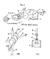
- MINI Three special treatment units or field applicators, herein referred to as MINI, MOYI and MAXI; and four different types of flexible and/or adaptable mechanical supports (three of which contain one or two adjustable-pressure disc-breaks), for manipulating the treatment applicators in any desired direction in space; a simple support for MINI field applicator, floor and/or wall supports for the three field applicators (MINI, MOYI, and MAXI), and a 4-wheel carriage support for increased mobility of any of the three field applicators (this mobile carriage can be used for treating patients in standard hospital beds or otherwise.)
- the present improved Electromagnetic Therapy System has a wide range of biomedical applications because of the following features:
- This system can generate numerous desirable, controllable and useful Low-Frequency Electro-Magnetic (LF-EM) treatment characteristics.
- LF-EM Low-Frequency Electro-Magnetic
- the following parameters of the LF-EM field can be selected or predetermined by this system:
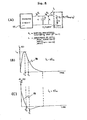
- an electro-magnetic low-frequency therapeutic system comprising a magnetization coil for creating an electro-magnetic field, means to secure said coil in a predetermined fixed position, generator means for feeding said coil with predetermined treatment signals to obtain a desired magnetic field characteristic, control circuit means for selecting desired characteristics of said treatment signals, said control circuit means having (i) circuit control means for controlling the peak intensity of said desired magnetic field, (ii) frequency control means to select the interruption frequency of said treatment signals to obtain a selected type of a plurality of therapeutic signals, (iii) adjustment means to preset the duration time of said treatment signals and said electro-magnetic field, said desired magnetic field characteristic being predetermined from a magnetic field pattern chart representative of the parameters of the field of said magnetization coil in the surrounding environment of said coil-whereby to obtain a desired range of intensity of the field and a desired orientation thereof relative to a position of the coil.
- a method of obtaining a desired electro-magnetic field at points in space in close surrounding environment of a magnetization coil comprising the steps of: (i) providing a field pattern chart of said coil to display the orientation of iso- magnetic field lines of said coil to define the pattern of the intensity and to display the direction of said magnetic field in space, said field lines being relative to a scale with respect to said coil; (ii) selecting an area in said field pattern chart having a desired field intensity range and field directions; (iii) orienting said coil with respect to a desired location in space to position said selected area thereon; (iv) generating controlled treatment signals to said coil to obtain said desired field intensity range and to select a time/fre- quency/amplitude/modulation of said field intensity; and (v) applying said treatment signals for generating said magnetic field for a predetermined period of time.
- the electro-magnetic therapeutic system of the present invention comprising different magnetization coils 11 (MINI), 12 (MOYI) and 13 (MAXI) and a control unit or generator 10 of two possible versions, one pulsating 10(a) and one sinusoidal version 10(b), for establishing a predetermined electromagnetic field characteristic in the magnetization coil 12 or 13 or in the surrounding of the magnetization coil 11.
- A the maximum amplitude setting
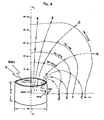
- the direction of the magnetic field is indicated.
- Said field lines indicating intensity and direction of field are symmetrical in space with respect to the longitudinal axis xl - x2 .
- the intensity of the magnetic field is of the order of magnitude of the terrestrial magnetic field (below 1G).
- the direction of the field is indicated by arrows.
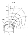
- Said field lines indicating intensity and direction of field are symmetrical in space with respect to the longitudinal axis x l - x 2 .
- the intensity of the magnetic field is of the order of magnitude of the terrestrial magnetic field (below 1 Gauss).
- the direction of the magnetic field is indicated by arrows.
- Said field lines indicating intensity and direction of field are symmetrical in space with respect to the longitudinal axis x l - x 2 .
- the intensity of the magnetic field is of the order of magnitude of the terrestrial magnetic field (below 1 Gauss).
- the field applicators, 11, 12 and 13 are used for treatments such as shown in Figures lA, B, C, D and E illustrations, and such as further illustrated by the different combinations of generators, treatment applicators and mechanical supports shown in Figures 3A and B illustrations.
- the MOYI and MAXI treatment applicators are air coils and the MINI treatment applicator is a core coil as further described in Tables 1 and 2 hereinbefore.
- the charging circuit 77 is fed by an alternating current supply, 50 or 60 Hz 115 or 230 Volts as further illustrated in Figure 13.
- V o is the maximum voltage to which the capacitor C is charged;
- t i is the period of time from the beginning of the current pulse to the time where the second deriva- d 2 i tive of the current i c is equal to zero;
- All three treatment applicators 11, 12 and 13 can be connected to any of the two versions of the generators 10(a) and 10(b) using a jack connector 32, 33, or 35 which fits its female jack connector 36.
- Mechanical versatility is still increased by the use of four different types of modular supports which are constructed with a minimum number of standardized parts such as an articulated joint 21, 22, 37, 38 and 46; non-magnetic stainless steel 1 1/4 inch rods 20, 39, 56 and 48 (bigger rod, 1 1/2 inch), galvanized 8 x 8 inch aluminum plates 25, 41, and 51 are fixed with non-magnetic stainless steel screws 26, base plates 15, 16 which can be made of wood covered with suitable material.
- Casters 52, 54 can be fixed to the base of different mechanical supports 15 and 16, the rear wheels 54 are equipped with a braking mechanism 53 and they are mounted on a rotating base.
- the base 15 and 16 of mechanical supports can also be fixed to a wall or to the ceiling of a treatment room.
- the base plate 25, 41 or 51 can be fixed in the middle of the support base 15 or 16 when mechanical stability is preserved for a given set-up of mechanical support.
- Figure 1C shows a simple mechanical support 14 composed of a comfortable cushion 17 and a simple rect-angular box to keep the treatment applicator 11 in the desired position.
- Different height adjustment inserts small wedges or boards
- Support plates 40 and 55 hold the coil 12 and the coil 13 to the base 62 of the articulated joint 37, 46, illustrated in Figure 2.
- This joint 21, 22, 37, 38 or 46 is composed of a break holder 57, a large flat end screw 58, 59 with a lock pin 60, a thin frictional disc 63, a cylindrical part 64 with a hole 65 to receive the rods 20, 39 or 56. These rods can be rigidly fixed in the hole 65 by tightening two allen screws 67 which cause the slot 66 to narrow.
- a handle 23, 24, is used to adjust the brake pressure by pressing all parts of the disc brake together when the handle 23, 24 is screwed on the flat end screw 58, 59.
- Figure 2B shows the details of a connector 47 which serves to hold the rods 48 and 56 at perpendicular angles between each other, while allowing the rods to be partially moved and locked in desired positions.
- the adjustment is provided by flexible slots adjusted with pressure screws 47(a) and 47(b); a mechanical coupling 49-50 holds the rod 48 to the base plate 51 (see Figure 2C).
- the screw nut 49 is used to tighten the threaded slotted rod end 50 onto the vertical rod 48.
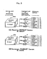
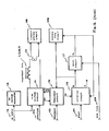
- FIG. 3 is a block diagram showing different combinations of generators 10(a) or 10(b), treatment applicators 11, 12 or 13 and mechanical supports 14, 15, 16 of the Electromagnetic Therapy System.
- Figure 4 and Figure 6 show the three field applicators 11, 12, and 13 with their respective field pattern chart as described hereinbefore.
- the field generator 10, 10(a) and 10( b ) The system is intended for medical use and for multiple treatments.
- the treatment is generated by a magnetization coil 11, 12, 13 properly coupled and fed by a sinusoidal or a pulsating generator 10(a) and 10(b).
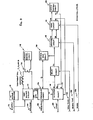
- Most of the characteristics of the magnetic field created by the system are selected by the controls on the front panel of the generator 10 as illustrated in Figure 7.
- the electro- magnetic field is pulsed ( Figures 8, 12 and 13) and in a second option, the electro-magnetic field is sinusoidal ( Figures 9, 11 and 15).
- the magnetic field has five characteristics which are adjustable by the controls on the panel 68 of the control unit 10.
- the first control 69 controls the amplitude or intensity of the electro-magnetic field from 0 to 100% as herein shown in increments of 10%.
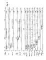
- the control 70 controls the frequency of interruption of the fundamental signal of the electro-magnetic field in the order of 1, 2, 4, 8, and 16 cycles of the periodic field, see Figures 14 and 16 for detailed illustration, with an interruption time respectively equal to 1, 2, 4, 8 and 16 cycles of the periodic field, see also Figures 14 and 16.
- the magnetization time is set by the control 71 and at the termination of the magnetization time, the second phase or the demagnetization phase of the treatment takes place.
- This demagnetization phase has a time period set by the control 72.
- the demagnetization can be made in accordance with a linear or quasi-exponential characteristic as will later be described with reference to Figure 15.
- the switch 73 sets the desired characteristic of the demagnetization phase either for linear or exponential demagnetization.
- Switch 74 is an "ON" switch for the system while switch 75 is the switch which starts the treatment and the various timers are synchronized with the switch 75.
- Indicator light 76 indicates the start and tenmination of the treatment and that current effectively flows through the treatment applicator 11, 12 or 13.
- a jack 36 is provided to connect the magnetization coil 11, 12 or 13 to the generator 10.
- This set of values represent what is named the critical damping design for the given values of t m and L.
- Other embodiments of the present invention can easily be reached by using the same set of simultaneous equations for desired values of t and L. It is intended that the m numerical value of the components R L , L and C of the pulse shaping circuit can be changed so as to cause the peak amplitude of the said current pulse 78 to decrease by not more than 50% of that resulting from the critical damping design defined above and the resulting design is included in the present invention and is an embodiment of it.
- connection 10 connects to the switch 75 to start the treatment by operating an initiation circuit 115.
- the treatment will be effected as set by the controls on the generator 10.
- An audible circuit 108 is actuated during the period of treatment.
- the current monitor circuit 109 operates the indicator lamp 76 on the console 10.
- the amp - litude is automatically varied by means of an amplitude circuit 118, a mode circuit 119, and an electromagnetic system 110 including a motor (not shown) coupled to a variable transformer incorporated in the "High Voltage Circuit".
- the interruption of the electromagnetic field to produce pulse signals is effected by means of a power semi-conductor (Silicon Controlled Rectifier, SCR) in the high voltage circuit 111.
- SCR Power semi-conductor
- the entire control unit is fed by a 60 cycle 115 volt supply or 50 cycle 230 volt supply at 112. It is the frequency of the A.C. voltage 112 that determines the fundamental frequency of the magnetic field treatment.
- a 12 volt D.C. voltage regulated and unregulated is also provided to feed the various electronic and electro-magnetic circuits in the apparatus.
- the various controls 69, 70, 71 and 72 are represented in Figure 9 at inputs 102, 103, 104 and 105.
- the mode switch 73 is represented at 106.
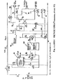
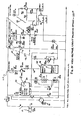
- the high voltage circuit 111 feeds the current to the magnetization coil 11, 12 or 13 and includes a variable auto-transformer Tl which permits to adjust the maximum current for a given treatment to the desired value.
- a voltage transformer T5 lowers the voltage in a manner whereby to obtain a current of high intensity in the coil 11, 12 or 13.
- a semi-conductor of the TRIAC type Q1 permits the interruption of the current in accordance to the desired magnetic field pattern. This TRIAC Ql is controlled by a signal OP2.
- a capacitor C3-C5 in the application of a pulse magnetic field, a capacitor C3-C5 is charged with the current in the secondary of the auto-transformer Tl. The capacitor C3-C5 is then discharged in the treatment coil 11, 12 or 13 and produces a pulse current of high intensity. This is achieved by means of an SCR semi-conductor Q3 controlled by a signal OP4. This signal corresponds to the signal OP3 of the capacitor charging circuit 77 except that it is delayed and that the current pulses 78 correspond to the negative cycle of the sinusoidal signal.
- a detector circuit named zero voltage switch 120 is used to detect the near-zero tension of the A.C. supply 112 and to generate the synchronization signal OP1 as shown in Figures 11 and 13.
- a small cooling fan 121 is used to cool down the damping resistors R8-Rll (5 ⁇ , 250W).
- an extra input-auto-transformer is used to reduce this voltage to 115 volts 50 Hz.
- the D.C. voltage regulator circuit 113 utilizes a transformer which reduces the voltage as is necessary to supply the circuits. A regulator is also used to obtain a continuous voltage of 12 volts and an unregulated 12 volts D.C.
- the current monitor circuit 109 includes a current transformer 114 (T6 and T2 on Figures 11 and 13) which feeds the indicator lamp 76 which permits visual indication that current flows through the magnetization coil 11, 12, 13.
- the initiation circuit 115 is operated by the start switch 75 and is placed in operation by the first pulse of the signal ZC which is similar to the signal OP1.
- the signal MU at one of the outputs of the circuit 115 determines the speed of the motor acting to position T2 ( Figure 11).
- the signal Q commands the first phase of the treatment ( Figures 9 and 10), that is, the MAG TIME phase.
- the signal MR appears at the.end of the DEMAG TIME and resets all the circuits and the position of the auto-transformer T2 ( Figures 9, 10 and 11).
- the frequency circuit 116 (116S and 116P on Figures 11 and 13) produces an interruption of the magnetization current at a predetermined frequency 103. It generates a series of pulses TR ( Figure 10).
- the signal OP2 (or OP4) is retarded relative to the signal OP1 (and OP1 and OP3 in the pulsating case) in such a manner to interrupt the passage of the current in the treatment coil as illustrated in Figures 10, see ZC, Fl, F2...F6 and in Figures 14 and 16, see Fl, F2,...F6.
- the delay circuit 117 Figure 9, generates the time period of the MAG TIME of the treatment as predetermined by the setting on the control 71. At the end of MAG TIME, the signal DL commands the other circuits.
- the audible tone circuit 108 produces two different frequencies in accordance with the various sections of the treatment. It is operated by the signal Q. The change of the tone of the signal is controlled by the signal DL.
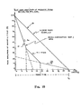
- the amplitude circuit 118 generates a signal FD of a predetermined frequency in accordance with the function of the DEMAG TIME 105 and set by the control 72. This circuit is controlled by the signal DL during the second phase or the DEMAG TIME of the treament. This circuit also generates a time base TB. The time unit of this time base is variable in accordance with the setting of the DEMAG switch 72, and allows for generating differ- e nt demagnetization curves as illustrated in Figure 15, where DEMAG TIME is equal to t f , 30 seconds for the case illustrated.
- the mode circuit 119 generates a linear curve or a quasi-exponential curve of initial amplitude equal to the peak amplitude of the magnetic field generated during the MAG TIME. This choice is established by the mode switch 73.
- the time base signal will modify the frequency signal FD in such a way as to produce a second signal MD of which the frequency will control the speed of the motor in circuit 110.
- This motor is a step-by-step motor and the direction of rotation of this motor is determined by the signal MU or MD.
- This motor is fed by a 12 volt supply and controlled by means of transistors.
- This motor operates a variable auto-transformer T2 which in turn modifies the current in the magnetization coil 11, 12 or 13 whereby to demagnetize the coil in accordance with the preset mode characteristic 73, 90, 91 (Figs. 7 & 15).
- Figure 12 includes the same component parts of the circuit described in Figure 9 with the exception that it is restricted to the pulse mode, whereas in Figure 9, there is shown both the pulse and the sinus modes.
- the basic wave form is a sinusoidal wave form which is either a 60 or 50 HZ signal depending on the frequency supply of the input voltage 112.
- the resulting treatment frequencies Fl, F2, ...F6 will be equal to 50 Hz, 25 Hz 12.5 Hz, 6.25 H z, 3.125 Hz and 1.56 Hz, for both sinus and pulse options.
- Figure 15 is an illustration of the characteristic of the demagnetization curves when the system is utilized in the linear or the quasi-exponential mode.
- the characteristic of the linear mode is shown at 90 and the quasi-exponential mode is shown at 91.
- the DEMAG TIME t f .5, 1, 1.5 min., etc. as shown on the control 72 of Figure 7.
- Figure 16 shows the electromagnetic field patterns for the pulse option.
- the shape of individual pulses is as described above, see Figure 8 and its description hereinbefore.
- Ri-2000 RHUMART-THERAPY SYSTEM specifications SUMMARY Voltage supply: 110 or 220 VAC, 60/50 Hz Max. Power requirement: Ri-2000S: approx. 330 W Ri-2000P: approx. 550 W Fuse: Ri-2000S: approx..5 Amp. Ri-2000P: approx. 5 Amp. Field intensity*: adjustable 0-100 gauss (peak), with MAXI.
- Basic Sinusoidal or Pulse Frequency 60/50 Hz
- Treatment-modulation frequencies 60 Hz, 30 Hz, 15 Hz, 7.5 Hz, 3.75 Hz and 1.875 Hz; or: 50 Hz, 25 Hz, 12.5 Hz, 6.25 Hz, 3.125 Hz, 1.56 Hz. (depending on the basic frequency: 60 or 50 Hz)
- TIME 0.5, 1.0, 1.5, 2.0, 2.5, 3.0, 5.0, 10, 15, 20, 25, and 30 min -
- EMAG TIME 0.5, 1.0, 1.5, 2.0, 2.5, 3.0, 5.0, 10, 15, 20, 25, and 30 min (Duration of treatment-MAG. TIME + DEMAG.
- the Ri-2000S sinusoidal field system is particularly indicated to complete a treatment course, as the DEMAGNETIZATION phase (during DEMAG TIME) of the treatment automatically causes the amplitude of the field to decrease at a desired rate (0.5 min. to 30 min. period) for a choice of two different decay modes (LINEAR or EXPONENTIAL).
- the treatment should always be carried out with a 30% initial amplitude, frequency and time when the asterisk ( * ) is shown in the TABLE OF INDICATIONS (Table 3); the second treatment can reach 70% of the desired amplitude, frequency and time; only the third treatment should be carried out with the desired maximum values-given in the TABLE OF INDICATIONS.
- the subjective feelings of the patients should be used as an indicator.
- the duration of treatment varies from 0.5 to 30 minutes daily, up to 3 times a week, 2 times a week and sometimes weekly.
- the total number of treatments depends on the state of the individual case and it varies from patient to patient.
- the Ri-2000S may also be used advantageously to complete a treatment course, as the DEMAGNETIZATION phase provided by this system automatically causes the amplitude of the field to decrease at a desired rate, as described hereinbefore.
- the FREQUENCY of any periodic process is the number of full cycles within a time interval (second).
- pulse frequency is the repetition frequency of pulse bundles, in bundles per second (Hz).
- the basic frequency is the frequency of repetition of pulses in each pulse bundle (60 Hz or 50 Hz, depending on the frequency of the sinusoidal current supplied to the control unit);
- pulse freguency is the repetition frequency of the sinusoidal wave bundles, in bundles per second (Hz).
- the basic freauency is the frequency of the sinusoidal field in each sine wave bundle (60 Hz or 50 Hz, depending on the frequency of the sinusoidal current supplied to the control unit).
- a "pulse frequency” range between 1.56 Hz to 60 Hz is used. This frequency range (1.56 - 60 Hz) is divided in two frequency domains which are used for most therapeutic aprlications: i.e. .
- the LOW FREQUENCY range (below 7.5 Hz) is used for treatment of ACUTE INFLAMMATORY process, and the HIGHER FREQUENCY range (above 25 Hz) is used for treatment of CHRONIC DEGENERATIVE processes.
- Higher dosage (i.e. frequency above 25 Hz, intensity of field above 50 Gauss and time period of treatment longer than 10 minutes) should be applied for treating degenerative disorders caused by chronic inflammatory processes such as:
- low dosages should be used: (frequency below 7.5 Hz, intensity of field below 30 Gauss and time period of treatment below 10 minutes).
- RHUMART-therapy can be combined with classical medical procedures such as balneological procedures and chemotherapy (with the exception of antibiotics and bacteriological treatments where RHUMART-therapy is not recommended).
- the therapies of nature-cure practitioners such as neural therapy (using electric currents) and ozone therapy (or negative ion therapy); as well as all homeopathic treatment modalities can be advantageously combined with RHUMART-therapy.
- RHUMART-therapy can be used either simultaneously, before or immediately after the treatment combined with RHUMART-therapy.
Landscapes
- Health & Medical Sciences (AREA)
- Engineering & Computer Science (AREA)
- Biomedical Technology (AREA)
- Nuclear Medicine, Radiotherapy & Molecular Imaging (AREA)
- Radiology & Medical Imaging (AREA)
- Life Sciences & Earth Sciences (AREA)
- Animal Behavior & Ethology (AREA)
- General Health & Medical Sciences (AREA)
- Public Health (AREA)
- Veterinary Medicine (AREA)
- Magnetic Treatment Devices (AREA)
- Electrotherapy Devices (AREA)
Applications Claiming Priority (3)
| Application Number | Priority Date | Filing Date | Title |
|---|---|---|---|
| US19022280A | 1980-09-24 | 1980-09-24 | |
| CA000360907A CA1150361A (en) | 1980-09-24 | 1980-09-24 | Electro-magnetic therapeutic system and method |
| US190222 | 1980-09-24 |
Publications (1)
| Publication Number | Publication Date |
|---|---|
| EP0048451A1 true EP0048451A1 (de) | 1982-03-31 |
Family
ID=25669151
Family Applications (1)
| Application Number | Title | Priority Date | Filing Date |
|---|---|---|---|
| EP81107360A Withdrawn EP0048451A1 (de) | 1980-09-24 | 1981-09-17 | Elektromagnetisches therapeutisches System und Verfahren |
Country Status (3)
| Country | Link |
|---|---|
| EP (1) | EP0048451A1 (de) |
| JP (1) | JPS57117872A (de) |
| CA (1) | CA1150361A (de) |
Cited By (52)
| Publication number | Priority date | Publication date | Assignee | Title |
|---|---|---|---|---|
| DE3327920A1 (de) * | 1982-09-21 | 1984-10-04 | Ken Hashimoto | Elektromagnetische therapeutische vorrichtung |
| GB2145317A (en) * | 1983-07-16 | 1985-03-27 | Hayashibara Ken | Method for promoting the productivity of animals, plants and microorganisms |
| EP0145173A1 (de) * | 1983-10-17 | 1985-06-19 | Electro-Biology, Inc | Veränderung der Blutzirkulationsdynamik in einem lebenden Körper |
| US4551781A (en) * | 1983-08-03 | 1985-11-05 | Chris G. Nicholson | Control circuit for magnetic probe |
| EP0181053A2 (de) * | 1984-09-12 | 1986-05-14 | Irt, Inc. | Vorrichtung zur Therapie mittels eines impulsförmigen elektromagnetischen Feldes mit Selbstvormagnetisierungsschaltung und Verfahren zum Gebrauch |
| EP0182160A1 (de) * | 1984-11-09 | 1986-05-28 | Daber S.R.L. | Gerät zur Abgabe einer Folge von annähernd halbkreisförmigen magnetischen Impulsen |
| EP0223354A2 (de) * | 1985-09-11 | 1987-05-27 | Elizabeth A. Rauscher | Vorrichtung zur Modulation von Gehirnsignalen durch ein äusserliches Magnetfeld zur Reduktion von Schmerz |
| EP0332086A1 (de) * | 1988-03-04 | 1989-09-13 | Gerhard Bohn | Betteil |
| EP0380681A1 (de) * | 1988-04-25 | 1990-08-08 | 2 Moskovsky Gosudarstvenny Meditsinsky Institut Imeni N.I.Pirogova | Magnetotherapie-anordnung |
| EP0403642A1 (de) * | 1989-01-09 | 1990-12-27 | LIFE RESONANCES, INC. (a Montana corporation) | Unblutige behandlung von osteoporose mittels magnetischer felder |
| DE3937793A1 (de) * | 1989-11-14 | 1991-05-16 | Datron Electronic Gmbh | Vorrichtung zur induktiven stimulation von erregbarem gewebe |
| EP0528964A1 (de) * | 1990-05-04 | 1993-03-03 | Bio-Magnetic Therapy Systems, Inc. | Therapie durch magnetisches feld und gerät dafür |
| US5215642A (en) * | 1986-10-27 | 1993-06-01 | Life Resonances, Inc. | Improved method and apparatus for regulating transmembrane ion movement |
| US5215633A (en) * | 1986-10-27 | 1993-06-01 | Life Resonances, Inc. | Techniques for enhancing the permeability of ions through membranes |
| GB2270000A (en) * | 1992-08-26 | 1994-03-02 | Robert John Grace | Magnetic field induction multi - pulse therapy. |
| US5314400A (en) * | 1988-04-25 | 1994-05-24 | Tsyb Anatoly F | Device for magnotherapy |
| EP0601545A2 (de) * | 1992-12-08 | 1994-06-15 | Electro-Biology, Inc | Verbesserung der biologischen Reaktion durch selektives Spektrum-Entfernen bei elektromagnetischer Reizung mit Impulsfeldern |
| EP0641232A4 (de) * | 1989-10-05 | 1995-01-09 | Tn Bioelectronics Pty Ltd | Behandlung an lebenden körpern. |
| AT399280B (de) * | 1990-05-17 | 1995-04-25 | Othmar Handl Gesmbh | Vorrichtung zur wärmebehandlung von tumoren |
| GB2277270B (en) * | 1991-12-20 | 1996-01-03 | Free World Trust | Electrophysiological conditioning system and method |
| US5527259A (en) * | 1992-08-26 | 1996-06-18 | Circuitry Systems Limited | Magnetic field induction multi-pulse therapy |
| WO1996036207A1 (fr) * | 1995-05-19 | 1996-11-21 | Nikolai Fedorovich Morozov | Procede de traitement de semences avant semailles et dispositif de realisation |
| US6083149A (en) * | 1997-10-22 | 2000-07-04 | Emf Therapeutics, Inc. | Magnetic field device and method for inhibiting angiogenesis and retarding growth rates of tumors in mammals |
| US6149577A (en) * | 1999-03-18 | 2000-11-21 | Emf Therapeutics, Inc. | Apparatus and method for creating a substantially contained, finite magnetic field useful for relieving the symptoms pain and discomfort associated with degenerative diseases and disorders in mammals |
| WO2004000418A1 (en) * | 2002-06-25 | 2003-12-31 | Charles Rory Orr | Magnetotherapeutic device |
| ES2224887A1 (es) * | 2004-04-07 | 2005-03-01 | Tesla Therapeutics, S.L. | Sistema para la reduccion del dolor cronico en patologia osteomuscular lumbar y procedimiento de aplicacion del mismo. |
| EP1563869A1 (de) * | 2004-02-11 | 2005-08-17 | Richard Markoll | Vorrichtung zur Behandlung eines Patienten mittels eines elektromagnetischen Feldes |
| WO2007044386A3 (en) * | 2005-10-05 | 2008-01-17 | Electromagnetic Resources Inc | Electromagnetic fields for systemic effect in therapy |
| WO2009090440A1 (en) * | 2008-01-18 | 2009-07-23 | Tivi Kft | System for the treatment of diabetes |
| WO2011098638A1 (es) | 2010-02-10 | 2011-08-18 | Pneuma Research, S.L. | Dispositivo transductor digital portátil, programable con alta discriminación en baja frecuencia y de baja intensidad |
| US8062229B2 (en) | 2007-08-10 | 2011-11-22 | Rauscher Elizabeth A | Methods and devices for measurement and treatment of pain and the treatment of inflammation and osteoporosis |
| WO2016001914A1 (en) * | 2014-06-30 | 2016-01-07 | BrainQ Technologies Ltd. | Therapeutic electromagnetic field |
| US9737725B2 (en) | 2007-08-10 | 2017-08-22 | Elizabeth A. Rauscher | Enhancement of biological functioning by the use of electromagnetic and magnetic fields |
| US9801905B2 (en) | 2014-03-13 | 2017-10-31 | Hossam Abdel Salam El Sayed Mohamed | Use of organic sulphur, antioxidants, and amino acids in conjunction with exercise and electromagnetic stimulation to treat osteoporosis |
| CN110090358A (zh) * | 2018-01-29 | 2019-08-06 | 邦尼塔斯研究中心有限公司 | 血液磁刺激装置 |
| US10967194B2 (en) | 2018-05-02 | 2021-04-06 | Shealy-Sorin Wellness, Llc | Pulsed electromagnetic field device and methods of use |
| US11185690B2 (en) | 2016-05-23 | 2021-11-30 | BTL Healthcare Technologies, a.s. | Systems and methods for tissue treatment |
| US11247039B2 (en) | 2016-05-03 | 2022-02-15 | Btl Healthcare Technologies A.S. | Device including RF source of energy and vacuum system |
| US11247063B2 (en) | 2019-04-11 | 2022-02-15 | Btl Healthcare Technologies A.S. | Methods and devices for aesthetic treatment of biological structures by radiofrequency and magnetic energy |
| US11253717B2 (en) | 2015-10-29 | 2022-02-22 | Btl Healthcare Technologies A.S. | Aesthetic method of biological structure treatment by magnetic field |
| US11253718B2 (en) | 2015-07-01 | 2022-02-22 | Btl Healthcare Technologies A.S. | High power time varying magnetic field therapy |
| US11266852B2 (en) | 2016-07-01 | 2022-03-08 | Btl Healthcare Technologies A.S. | Aesthetic method of biological structure treatment by magnetic field |
| US11464993B2 (en) | 2016-05-03 | 2022-10-11 | Btl Healthcare Technologies A.S. | Device including RF source of energy and vacuum system |
| US11464994B2 (en) | 2016-05-10 | 2022-10-11 | Btl Medical Solutions A.S. | Aesthetic method of biological structure treatment by magnetic field |
| US11484727B2 (en) | 2016-07-01 | 2022-11-01 | Btl Medical Solutions A.S. | Aesthetic method of biological structure treatment by magnetic field |
| US11491342B2 (en) | 2015-07-01 | 2022-11-08 | Btl Medical Solutions A.S. | Magnetic stimulation methods and devices for therapeutic treatments |
| US11491329B2 (en) | 2020-05-04 | 2022-11-08 | Btl Healthcare Technologies A.S. | Device and method for unattended treatment of a patient |
| US11534619B2 (en) | 2016-05-10 | 2022-12-27 | Btl Medical Solutions A.S. | Aesthetic method of biological structure treatment by magnetic field |
| US11612758B2 (en) | 2012-07-05 | 2023-03-28 | Btl Medical Solutions A.S. | Device for repetitive nerve stimulation in order to break down fat tissue means of inductive magnetic fields |
| US11633596B2 (en) | 2020-05-04 | 2023-04-25 | Btl Healthcare Technologies A.S. | Device and method for unattended treatment of a patient |
| US11896816B2 (en) | 2021-11-03 | 2024-02-13 | Btl Healthcare Technologies A.S. | Device and method for unattended treatment of a patient |
| US12064163B2 (en) | 2021-10-13 | 2024-08-20 | Btl Medical Solutions A.S. | Methods and devices for aesthetic treatment of biological structures by radiofrequency and magnetic energy |
Families Citing this family (11)
| Publication number | Priority date | Publication date | Assignee | Title |
|---|---|---|---|---|
| JPS59197262A (ja) * | 1983-04-23 | 1984-11-08 | 林原 健 | Ns磁束一対の強力磁気パルス細胞賦活装置 |
| JPS60210267A (ja) * | 1984-04-04 | 1985-10-22 | 中川 恭一 | パルス磁場治療器 |
| JPS60261471A (ja) * | 1984-06-08 | 1985-12-24 | 中川 恭一 | 磁場治療装置 |
| US4674482A (en) * | 1984-09-12 | 1987-06-23 | Irt, Inc. | Pulse electro-magnetic field therapy device with auto bias circuit |
| JPS61193672A (ja) * | 1985-02-24 | 1986-08-28 | 加藤 一郎 | 反転パルス電磁場による分散方法および装置 |
| JPS61159941U (de) * | 1985-03-23 | 1986-10-03 | ||
| JPS6389171A (ja) * | 1986-09-30 | 1988-04-20 | 小塚 洋司 | 誘導加熱素子の温度制御方法 |
| US4932951A (en) * | 1988-03-23 | 1990-06-12 | Life Resonances, Inc. | Method and apparatus for controlling tissue growth and an applied fluctuating magnetic field |
| JPH02232069A (ja) * | 1989-03-06 | 1990-09-14 | Shingo Ogasawara | 交流磁気治療装置 |
| DE9006057U1 (de) * | 1990-05-29 | 1991-09-26 | Kraus, Werner, Dipl.-Ing., 8000 München | Elektromedizinisches Gerät zum Erzeugen niederfrequenter Magnetfelder |
| JP2014090744A (ja) * | 2012-10-31 | 2014-05-19 | Soken Medical:Kk | 給電装置および磁気治療器 |
Citations (9)
| Publication number | Priority date | Publication date | Assignee | Title |
|---|---|---|---|---|
| FR674332A (fr) * | 1929-05-01 | 1930-01-27 | Perfectionnements aux appareils d'électricité médicale | |
| FR2169327A1 (de) * | 1972-01-28 | 1973-09-07 | Esb Inc | |
| US3841305A (en) * | 1972-10-25 | 1974-10-15 | Univ Iowa State Res Found Inc | External inductive neural stimulator system |
| FR2290224A1 (fr) * | 1975-02-10 | 1976-06-04 | Elmatron Gmbh Et Co Kg | Appareil pour favoriser la guerison des cellules d'organismes humains et animaux au moyen d'impulsions electromagnetiques |
| DE2553197A1 (de) * | 1975-11-27 | 1977-06-08 | Michael Buschky | Impulsfeldgenerator |
| DE2707574A1 (de) * | 1977-02-22 | 1978-08-24 | Goedde Geb Elsaesser Anna | Vorrichtung zur beeinflussung biologischer ablaeufe in einem lebenden koerper mit hilfe eines von einer spulenanordnung erzeugten magnetfeldes |
| FR2448354A1 (fr) * | 1979-02-02 | 1980-09-05 | Beaulieu Antonio | Methode et appareil pour le traitement du rhumatisme et maladies analogues |
| CA1102752A (en) * | 1979-02-07 | 1981-06-09 | John C. Martin | Freight transporter with load shifting mechanism |
| EP0039206A1 (de) * | 1980-04-23 | 1981-11-04 | Inoue-Japax Research Incorporated | Gerät zur magnetischen Behandlung |
Family Cites Families (2)
| Publication number | Priority date | Publication date | Assignee | Title |
|---|---|---|---|---|
| DE2314573C2 (de) * | 1973-03-23 | 1986-12-18 | Werner Dipl.-Ing. 8000 München Kraus | Gerät zur Förderung von Heilungsprozessen |
| JPS53103682A (en) * | 1977-02-18 | 1978-09-09 | Samy Kogyo Kk | Magnetic curing instrument |
-
1980
- 1980-09-24 CA CA000360907A patent/CA1150361A/en not_active Expired
-
1981
- 1981-09-17 EP EP81107360A patent/EP0048451A1/de not_active Withdrawn
- 1981-09-24 JP JP56149676A patent/JPS57117872A/ja active Granted
Patent Citations (10)
| Publication number | Priority date | Publication date | Assignee | Title |
|---|---|---|---|---|
| FR674332A (fr) * | 1929-05-01 | 1930-01-27 | Perfectionnements aux appareils d'électricité médicale | |
| FR2169327A1 (de) * | 1972-01-28 | 1973-09-07 | Esb Inc | |
| CA987391A (en) * | 1972-01-28 | 1976-04-13 | Michael R. Manning | Therapeutic bioelectric growth stimulator |
| US3841305A (en) * | 1972-10-25 | 1974-10-15 | Univ Iowa State Res Found Inc | External inductive neural stimulator system |
| FR2290224A1 (fr) * | 1975-02-10 | 1976-06-04 | Elmatron Gmbh Et Co Kg | Appareil pour favoriser la guerison des cellules d'organismes humains et animaux au moyen d'impulsions electromagnetiques |
| DE2553197A1 (de) * | 1975-11-27 | 1977-06-08 | Michael Buschky | Impulsfeldgenerator |
| DE2707574A1 (de) * | 1977-02-22 | 1978-08-24 | Goedde Geb Elsaesser Anna | Vorrichtung zur beeinflussung biologischer ablaeufe in einem lebenden koerper mit hilfe eines von einer spulenanordnung erzeugten magnetfeldes |
| FR2448354A1 (fr) * | 1979-02-02 | 1980-09-05 | Beaulieu Antonio | Methode et appareil pour le traitement du rhumatisme et maladies analogues |
| CA1102752A (en) * | 1979-02-07 | 1981-06-09 | John C. Martin | Freight transporter with load shifting mechanism |
| EP0039206A1 (de) * | 1980-04-23 | 1981-11-04 | Inoue-Japax Research Incorporated | Gerät zur magnetischen Behandlung |
Non-Patent Citations (1)
| Title |
|---|
| Medical and Biological Engineering, Vol. 11, No. 1, January 1973, Stevenage (GB) P.A. IBERG: "Magnetic Stimulation of Nerve Tissue", pages 55-63 * page 58 the two last paragraphs; page 61, figure 11; page 62, left-hand column, paragraph 4 * * |
Cited By (90)
| Publication number | Priority date | Publication date | Assignee | Title |
|---|---|---|---|---|
| GB2143131A (en) * | 1982-09-21 | 1985-02-06 | Ken Hashimoto | Therapeutic devices |
| DE3327920A1 (de) * | 1982-09-21 | 1984-10-04 | Ken Hashimoto | Elektromagnetische therapeutische vorrichtung |
| GB2145317A (en) * | 1983-07-16 | 1985-03-27 | Hayashibara Ken | Method for promoting the productivity of animals, plants and microorganisms |
| US4551781A (en) * | 1983-08-03 | 1985-11-05 | Chris G. Nicholson | Control circuit for magnetic probe |
| EP0145173A1 (de) * | 1983-10-17 | 1985-06-19 | Electro-Biology, Inc | Veränderung der Blutzirkulationsdynamik in einem lebenden Körper |
| US4723536A (en) * | 1984-08-27 | 1988-02-09 | Rauscher Elizabeth A | External magnetic field impulse pacemaker non-invasive method and apparatus for modulating brain through an external magnetic field to pace the heart and reduce pain |
| EP0181053A3 (de) * | 1984-09-12 | 1988-07-20 | Irt, Inc. | Vorrichtung zur Therapie mittels eines impulsförmigen elektromagnetischen Feldes mit Selbstvormagnetisierungsschaltung und Verfahren zum Gebrauch |
| EP0181053A2 (de) * | 1984-09-12 | 1986-05-14 | Irt, Inc. | Vorrichtung zur Therapie mittels eines impulsförmigen elektromagnetischen Feldes mit Selbstvormagnetisierungsschaltung und Verfahren zum Gebrauch |
| EP0182160A1 (de) * | 1984-11-09 | 1986-05-28 | Daber S.R.L. | Gerät zur Abgabe einer Folge von annähernd halbkreisförmigen magnetischen Impulsen |
| EP0223354A3 (en) * | 1985-09-11 | 1989-07-26 | Elizabeth A. Rauscher | Non-invasive method and apparatus for modulating brain signals through an external magnetic field to pace the heart and reduce pain |
| EP0223354A2 (de) * | 1985-09-11 | 1987-05-27 | Elizabeth A. Rauscher | Vorrichtung zur Modulation von Gehirnsignalen durch ein äusserliches Magnetfeld zur Reduktion von Schmerz |
| US5215642A (en) * | 1986-10-27 | 1993-06-01 | Life Resonances, Inc. | Improved method and apparatus for regulating transmembrane ion movement |
| US5215633A (en) * | 1986-10-27 | 1993-06-01 | Life Resonances, Inc. | Techniques for enhancing the permeability of ions through membranes |
| EP0332086A1 (de) * | 1988-03-04 | 1989-09-13 | Gerhard Bohn | Betteil |
| US5314400A (en) * | 1988-04-25 | 1994-05-24 | Tsyb Anatoly F | Device for magnotherapy |
| EP0380681A1 (de) * | 1988-04-25 | 1990-08-08 | 2 Moskovsky Gosudarstvenny Meditsinsky Institut Imeni N.I.Pirogova | Magnetotherapie-anordnung |
| EP0380681A4 (en) * | 1988-04-25 | 1992-07-08 | 2 Moskovsky Gosudarstvenny Meditsinsky Institut Imeni N.I.Pirogova | Magnetotherapy device |
| EP0403642A1 (de) * | 1989-01-09 | 1990-12-27 | LIFE RESONANCES, INC. (a Montana corporation) | Unblutige behandlung von osteoporose mittels magnetischer felder |
| EP0403642A4 (en) * | 1989-01-09 | 1992-06-24 | Life Resonances, Inc. (A Montana Corporation) | Using non-invasive magnetic fields for controlling osteoporosis |
| EP0641232A1 (de) * | 1989-10-05 | 1995-03-08 | Tn Bioelectronics Pty. Ltd. | Behandlung an lebenden körpern |
| EP0641232A4 (de) * | 1989-10-05 | 1995-01-09 | Tn Bioelectronics Pty Ltd | Behandlung an lebenden körpern. |
| DE3937793A1 (de) * | 1989-11-14 | 1991-05-16 | Datron Electronic Gmbh | Vorrichtung zur induktiven stimulation von erregbarem gewebe |
| EP0528964A4 (de) * | 1990-05-04 | 1994-02-23 | Bio Magnetic Therapy Sys Inc | |
| EP1371388A3 (de) * | 1990-05-04 | 2004-08-11 | Bio-Magnetic Therapy Systems, Inc. | Vorrichtung zur Behandlung von menschlichen Körpern mittels magnetischem Feld |
| EP0528964A1 (de) * | 1990-05-04 | 1993-03-03 | Bio-Magnetic Therapy Systems, Inc. | Therapie durch magnetisches feld und gerät dafür |
| EP0857494A3 (de) * | 1990-05-04 | 1999-04-21 | Bio-Magnetic Therapy Systems, Inc. | Vorrichtung zur Behandlung eines Körperorganes mittels Magnetfeldtherapie |
| EP0857494A2 (de) * | 1990-05-04 | 1998-08-12 | Bio-Magnetic Therapy Systems, Inc. | Vorrichtung zur Behandlung eines Körperorganes mittels Magnetfeldtherapie |
| US5453073A (en) * | 1990-05-04 | 1995-09-26 | Bio Magnetic Therapy Sys Inc | Apparatus for treatment of diseased body organs with magnetic field therapy |
| AT399280B (de) * | 1990-05-17 | 1995-04-25 | Othmar Handl Gesmbh | Vorrichtung zur wärmebehandlung von tumoren |
| GB2277270B (en) * | 1991-12-20 | 1996-01-03 | Free World Trust | Electrophysiological conditioning system and method |
| GB2270000B (en) * | 1992-08-26 | 1996-04-24 | Robert John Grace | Magnetic field induction multi-pulse therapy |
| US5527259A (en) * | 1992-08-26 | 1996-06-18 | Circuitry Systems Limited | Magnetic field induction multi-pulse therapy |
| GB2270000A (en) * | 1992-08-26 | 1994-03-02 | Robert John Grace | Magnetic field induction multi - pulse therapy. |
| EP0601545A2 (de) * | 1992-12-08 | 1994-06-15 | Electro-Biology, Inc | Verbesserung der biologischen Reaktion durch selektives Spektrum-Entfernen bei elektromagnetischer Reizung mit Impulsfeldern |
| EP0601545A3 (en) * | 1992-12-08 | 1996-03-13 | Electro Biology Inc | Improved electromagnetic bioresponse by selective spectral suppression, in pulsed field stimulation. |
| WO1996036207A1 (fr) * | 1995-05-19 | 1996-11-21 | Nikolai Fedorovich Morozov | Procede de traitement de semences avant semailles et dispositif de realisation |
| US6083149A (en) * | 1997-10-22 | 2000-07-04 | Emf Therapeutics, Inc. | Magnetic field device and method for inhibiting angiogenesis and retarding growth rates of tumors in mammals |
| US6149577A (en) * | 1999-03-18 | 2000-11-21 | Emf Therapeutics, Inc. | Apparatus and method for creating a substantially contained, finite magnetic field useful for relieving the symptoms pain and discomfort associated with degenerative diseases and disorders in mammals |
| WO2004000418A1 (en) * | 2002-06-25 | 2003-12-31 | Charles Rory Orr | Magnetotherapeutic device |
| EP1563869A1 (de) * | 2004-02-11 | 2005-08-17 | Richard Markoll | Vorrichtung zur Behandlung eines Patienten mittels eines elektromagnetischen Feldes |
| US7588529B2 (en) | 2004-02-11 | 2009-09-15 | Richard Markoll | Apparatus for treating a patient's body using an electromagnetic field |
| ES2224887A1 (es) * | 2004-04-07 | 2005-03-01 | Tesla Therapeutics, S.L. | Sistema para la reduccion del dolor cronico en patologia osteomuscular lumbar y procedimiento de aplicacion del mismo. |
| WO2007044386A3 (en) * | 2005-10-05 | 2008-01-17 | Electromagnetic Resources Inc | Electromagnetic fields for systemic effect in therapy |
| US8062229B2 (en) | 2007-08-10 | 2011-11-22 | Rauscher Elizabeth A | Methods and devices for measurement and treatment of pain and the treatment of inflammation and osteoporosis |
| US9737725B2 (en) | 2007-08-10 | 2017-08-22 | Elizabeth A. Rauscher | Enhancement of biological functioning by the use of electromagnetic and magnetic fields |
| WO2009090440A1 (en) * | 2008-01-18 | 2009-07-23 | Tivi Kft | System for the treatment of diabetes |
| WO2011098638A1 (es) | 2010-02-10 | 2011-08-18 | Pneuma Research, S.L. | Dispositivo transductor digital portátil, programable con alta discriminación en baja frecuencia y de baja intensidad |
| US11612758B2 (en) | 2012-07-05 | 2023-03-28 | Btl Medical Solutions A.S. | Device for repetitive nerve stimulation in order to break down fat tissue means of inductive magnetic fields |
| US9801905B2 (en) | 2014-03-13 | 2017-10-31 | Hossam Abdel Salam El Sayed Mohamed | Use of organic sulphur, antioxidants, and amino acids in conjunction with exercise and electromagnetic stimulation to treat osteoporosis |
| WO2016001914A1 (en) * | 2014-06-30 | 2016-01-07 | BrainQ Technologies Ltd. | Therapeutic electromagnetic field |
| US11253718B2 (en) | 2015-07-01 | 2022-02-22 | Btl Healthcare Technologies A.S. | High power time varying magnetic field therapy |
| US11266850B2 (en) | 2015-07-01 | 2022-03-08 | Btl Healthcare Technologies A.S. | High power time varying magnetic field therapy |
| US11491342B2 (en) | 2015-07-01 | 2022-11-08 | Btl Medical Solutions A.S. | Magnetic stimulation methods and devices for therapeutic treatments |
| US11253717B2 (en) | 2015-10-29 | 2022-02-22 | Btl Healthcare Technologies A.S. | Aesthetic method of biological structure treatment by magnetic field |
| US11883643B2 (en) | 2016-05-03 | 2024-01-30 | Btl Healthcare Technologies A.S. | Systems and methods for treatment of a patient including RF and electrical energy |
| US11464993B2 (en) | 2016-05-03 | 2022-10-11 | Btl Healthcare Technologies A.S. | Device including RF source of energy and vacuum system |
| US11247039B2 (en) | 2016-05-03 | 2022-02-15 | Btl Healthcare Technologies A.S. | Device including RF source of energy and vacuum system |
| US11602629B2 (en) | 2016-05-03 | 2023-03-14 | Btl Healthcare Technologies A.S. | Systems and methods for treatment of a patient including rf and electrical energy |
| US11691024B2 (en) | 2016-05-10 | 2023-07-04 | Btl Medical Solutions A.S. | Aesthetic method of biological structure treatment by magnetic field |
| US11534619B2 (en) | 2016-05-10 | 2022-12-27 | Btl Medical Solutions A.S. | Aesthetic method of biological structure treatment by magnetic field |
| US11464994B2 (en) | 2016-05-10 | 2022-10-11 | Btl Medical Solutions A.S. | Aesthetic method of biological structure treatment by magnetic field |
| US11590356B2 (en) | 2016-05-10 | 2023-02-28 | Btl Medical Solutions A.S. | Aesthetic method of biological structure treatment by magnetic field |
| US11896821B2 (en) | 2016-05-23 | 2024-02-13 | Btl Healthcare Technologies A.S. | Systems and methods for tissue treatment |
| US11878162B2 (en) | 2016-05-23 | 2024-01-23 | Btl Healthcare Technologies A.S. | Systems and methods for tissue treatment |
| US11458307B2 (en) | 2016-05-23 | 2022-10-04 | Btl Healthcare Technologies A.S. | Systems and methods for tissue treatment |
| US11623083B2 (en) | 2016-05-23 | 2023-04-11 | Btl Healthcare Technologies A.S. | Systems and methods for tissue treatment |
| US11185690B2 (en) | 2016-05-23 | 2021-11-30 | BTL Healthcare Technologies, a.s. | Systems and methods for tissue treatment |
| US11628308B2 (en) | 2016-07-01 | 2023-04-18 | Btl Medical Solutions A.S. | Aesthetic method of biological structure treatment by magnetic field |
| US11794029B2 (en) | 2016-07-01 | 2023-10-24 | Btl Medical Solutions A.S. | Aesthetic method of biological structure treatment by magnetic field |
| US11484727B2 (en) | 2016-07-01 | 2022-11-01 | Btl Medical Solutions A.S. | Aesthetic method of biological structure treatment by magnetic field |
| US11607556B2 (en) | 2016-07-01 | 2023-03-21 | Btl Medical Solutions A.S. | Aesthetic method of biological structure treatment by magnetic field |
| US11497925B2 (en) | 2016-07-01 | 2022-11-15 | Btl Medical Solutions A.S. | Aesthetic method of biological structure treatment by magnetic field |
| US11524171B2 (en) | 2016-07-01 | 2022-12-13 | Btl Medical Solutions A.S. | Aesthetic method of biological structure treatment by magnetic field |
| US11266852B2 (en) | 2016-07-01 | 2022-03-08 | Btl Healthcare Technologies A.S. | Aesthetic method of biological structure treatment by magnetic field |
| US11679270B2 (en) | 2016-07-01 | 2023-06-20 | Btl Medical Solutions A.S. | Aesthetic method of biological structure treatment by magnetic field |
| CN110090358A (zh) * | 2018-01-29 | 2019-08-06 | 邦尼塔斯研究中心有限公司 | 血液磁刺激装置 |
| US10967194B2 (en) | 2018-05-02 | 2021-04-06 | Shealy-Sorin Wellness, Llc | Pulsed electromagnetic field device and methods of use |
| US11247063B2 (en) | 2019-04-11 | 2022-02-15 | Btl Healthcare Technologies A.S. | Methods and devices for aesthetic treatment of biological structures by radiofrequency and magnetic energy |
| US12076576B2 (en) | 2019-04-11 | 2024-09-03 | Btl Medical Solutions A.S. | Methods and devices for aesthetic treatment of biological structures by radiofrequency and magnetic energy |
| US11484725B2 (en) | 2019-04-11 | 2022-11-01 | Btl Medical Solutions A.S. | Methods and devices for aesthetic treatment of biological structures by radiofrequency and magnetic energy |
| US11491329B2 (en) | 2020-05-04 | 2022-11-08 | Btl Healthcare Technologies A.S. | Device and method for unattended treatment of a patient |
| US11826565B2 (en) | 2020-05-04 | 2023-11-28 | Btl Healthcare Technologies A.S. | Device and method for unattended treatment of a patient |
| US11813451B2 (en) | 2020-05-04 | 2023-11-14 | Btl Healthcare Technologies A.S. | Device and method for unattended treatment of a patient |
| US11878167B2 (en) | 2020-05-04 | 2024-01-23 | Btl Healthcare Technologies A.S. | Device and method for unattended treatment of a patient |
| US11806528B2 (en) | 2020-05-04 | 2023-11-07 | Btl Healthcare Technologies A.S. | Device and method for unattended treatment of a patient |
| US11633596B2 (en) | 2020-05-04 | 2023-04-25 | Btl Healthcare Technologies A.S. | Device and method for unattended treatment of a patient |
| US12029905B2 (en) | 2020-05-04 | 2024-07-09 | Btl Healthcare Technologies A.S. | Device and method for unattended treatment of a patient |
| US11679255B2 (en) | 2020-05-04 | 2023-06-20 | Btl Healthcare Technologies A.S. | Device and method for unattended treatment of a patient |
| US12064163B2 (en) | 2021-10-13 | 2024-08-20 | Btl Medical Solutions A.S. | Methods and devices for aesthetic treatment of biological structures by radiofrequency and magnetic energy |
| US11896816B2 (en) | 2021-11-03 | 2024-02-13 | Btl Healthcare Technologies A.S. | Device and method for unattended treatment of a patient |
Also Published As
| Publication number | Publication date |
|---|---|
| JPH0229340B2 (de) | 1990-06-28 |
| CA1150361A (en) | 1983-07-19 |
| JPS57117872A (en) | 1982-07-22 |
Similar Documents
| Publication | Publication Date | Title |
|---|---|---|
| EP0048451A1 (de) | Elektromagnetisches therapeutisches System und Verfahren | |
| CA2058179C (en) | Basic electrophysiological conditioning system and method | |
| US5453073A (en) | Apparatus for treatment of diseased body organs with magnetic field therapy | |
| US4315503A (en) | Modification of the growth, repair and maintenance behavior of living tissues and cells by a specific and selective change in electrical environment | |
| JP2844388B2 (ja) | 非侵入性磁界を利用して骨粗鬆症を制御する技術 | |
| US8961385B2 (en) | Devices and method for treatment of degenerative joint diseases with electromagnetic fields | |
| US6155966A (en) | Apparatus and method for toning tissue with a focused, coherent electromagnetic field | |
| KR100497500B1 (ko) | 자기 거울을 이용한 자극 코일 및 그 용도 | |
| US6447440B1 (en) | Apparatus and method for the treatment of disorders of tissue and/or the joints | |
| EP0062032B1 (de) | Elektromedizinischer behandlungsapparat | |
| US5269745A (en) | Method and apparatus for controlling tissue growth with an applied fluctuating magnetic field | |
| EP0338681B1 (de) | Vorrichtung zum Bestrahlen eines Gewebes mit einem magnetischen Feld | |
| EP0042889A1 (de) | Vorrichtung zur elektromagnetischen Körperbehandlung | |
| EP1439883B1 (de) | Vorrichtung zur elektromagnetischen therapie | |
| DE202019100003U1 (de) | Magnetfeld erzeugende Vorrichtung zur Behandlung eines Patienten | |
| US20040010177A1 (en) | Magnetic field stimulation techniques | |
| US20140046117A1 (en) | Apparatus and method for electromagnetic treatment of plant, animal, and human tissue, organs, cells, and molecules | |
| IE46078B1 (en) | Modification of the growth, repair and maintenance behaviour of living tissues and cells by a specific and selective change in electrical environment | |
| JPH07143971A (ja) | 神経細胞を磁気的に刺激する方法 | |
| US20080287730A1 (en) | Apparatus for Creating Therapeutic Charge Transfer in Tissue | |
| JPH0351431B2 (de) | ||
| EP0150211A1 (de) | Modifizierung des wachstums-, herstellungs- und unterhaltsverhältnisses lebender gewebe und zellen durch eine spezifische und selektive änderung der elektrischen umgebung | |
| EP1364679A2 (de) | Vorrichtung zur Erzeugung von mehreren Magnetfeldern zur Magnettherapie und Magnetakupunktur | |
| Barker | The design of a clinical electromagnetic bone stimulator | |
| FR2369850A1 (fr) | Appareil d'emission magnetique et electromagnetique a usage medical |
Legal Events
| Date | Code | Title | Description |
|---|---|---|---|
| PUAI | Public reference made under article 153(3) epc to a published international application that has entered the european phase |
Free format text: ORIGINAL CODE: 0009012 |
|
| AK | Designated contracting states |
Designated state(s): AT BE CH DE FR GB IT LI LU NL SE |
|
| 17P | Request for examination filed |
Effective date: 19820831 |
|
| RAP1 | Party data changed (applicant data changed or rights of an application transferred) |
Owner name: 121873 CANADA INC. |
|
| STAA | Information on the status of an ep patent application or granted ep patent |
Free format text: STATUS: THE APPLICATION IS DEEMED TO BE WITHDRAWN |
|
| 18D | Application deemed to be withdrawn |
Effective date: 19850103 |
|
| RIN1 | Information on inventor provided before grant (corrected) |
Inventor name: DROLET, ROLAND A. Inventor name: CHARLAND, GAETAN |