EP2907540A1 - Magnetisches Stimulationssystem - Google Patents
Magnetisches Stimulationssystem Download PDFInfo
- Publication number
- EP2907540A1 EP2907540A1 EP14192737.6A EP14192737A EP2907540A1 EP 2907540 A1 EP2907540 A1 EP 2907540A1 EP 14192737 A EP14192737 A EP 14192737A EP 2907540 A1 EP2907540 A1 EP 2907540A1
- Authority
- EP
- European Patent Office
- Prior art keywords
- coil
- pulse
- pulses
- stimulating coil
- voltage
- Prior art date
- Legal status (The legal status is an assumption and is not a legal conclusion. Google has not performed a legal analysis and makes no representation as to the accuracy of the status listed.)
- Withdrawn
Links
Images


Classifications
-
- A—HUMAN NECESSITIES
- A61—MEDICAL OR VETERINARY SCIENCE; HYGIENE
- A61N—ELECTROTHERAPY; MAGNETOTHERAPY; RADIATION THERAPY; ULTRASOUND THERAPY
- A61N2/00—Magnetotherapy
- A61N2/02—Magnetotherapy using magnetic fields produced by coils, including single turn loops or electromagnets
-
- A—HUMAN NECESSITIES
- A61—MEDICAL OR VETERINARY SCIENCE; HYGIENE
- A61N—ELECTROTHERAPY; MAGNETOTHERAPY; RADIATION THERAPY; ULTRASOUND THERAPY
- A61N1/00—Electrotherapy; Circuits therefor
- A61N1/40—Applying electric fields by inductive or capacitive coupling ; Applying radio-frequency signals
Definitions
- the disclosed subject matter relates to systems and methods for providing controllable pulse parameter magnetic stimulation that induces electric field pulses in a body organ.
- TMS Transcranial Magnetic Stimulation
- a pulsed current sent through a coil produces a magnetic field that induces an electric field in the brain, which can affect neuronal activity.
- a single TMS pulse can activate a targeted brain circuit.
- a TMS pulse delivered to the motor cortex can result in a twitch of the associated muscles in the body.
- a single TMS pulse can also disrupt neural activity.
- a TMS pulse delivered to the occipital cortex can mask the perception of a visual stimulus. This allows researchers to probe brain circuits on a millisecond time scale.
- a train of TMS pulses referred to as repetitive TMS (rTMS)
- rTMS repetitive TMS
- Repetitive TMS provides a means to study higher cognitive functions, and it could potentially be used as a therapeutic intervention in psychiatry and neurology.
- the neural response to TMS is sensitive to the parameters of the stimulating TMS pulse.
- the pulse width (PW), shape (e.g., sinusoidal vs. rectangular), and the relative amplitude of the positive and negative phases (degree of bidirectionality) of the induced electric field affect the physiological response to TMS, the power efficiency of the stimulator, and the heating of the stimulating coil.
- PW pulse width
- shape e.g., sinusoidal vs. rectangular
- degree of bidirectionality the relative amplitude of the positive and negative phases of the induced electric field
- Existing TMS systems are capable of inducing only damped cosine electric field pulse shapes, with a limited set of discrete choices of pulse width and degree of bidirectionality.
- monophasic magnetic field pulse shapes are associated with very low power efficiency of the stimulator in rTMS applications.
- One aspect is directed to a magnetic stimulation system for inducing approximately rectangular electric field pulses in a body organ, comprising an electrical energy storage device, a stimulating coil, and a switching means for electrically coupling said electrical energy storage device to said stimulating coil to produce current pulses in said stimulating coil which generates, in response to the current pulses, magnetic field pulses that can induce approximately rectangular electric field pulses in the body organ.
- a magnetic stimulation system for inducing approximately rectangular electric field pulses in a body organ, comprising a first and a second electrical energy storage device, a stimulating coil, a first switching means to electrically couple said first electrical energy storage device to the stimulating coil to produce current pulses with a positive rate of change in the stimulating coil, and a second switching means to electrically couple said second electrical energy storage device to said stimulating coil to produce current pulses with a negative rate of change in the stimulating coil, wherein the stimulating coil produces, in response to a combination of the current pulses with the positive and negative rates of change, magnetic field pulses that can induce approximately rectangular electric field pulses in the body organ.
- Another aspect is directed to a method of inducing approximately rectangular electric field pulses in a body organ with a magnetic stimulation system.
- the method comprises providing a first and a second energy storage device, providing a stimulating coil, providing a first switching means electrically coupled to the first energy storage device and the stimulating coil, providing a second switching means electrically coupled to the second energy storage device and the stimulating coil, actuating the first switching means to electrically couple the first energy storage device to the stimulating coil for a first period of time to produce current pulses with a positive rate of change in the stimulating coil, actuating the second switching means to electrically couple the second energy storage device to the stimulating coil for a second period of time to produce current pulses with a negative rate of change in the stimulating coil, and thereby causing the stimulating coil to produce, in response to a combination of the current pulses with the positive and negative rates of change, magnetic field pulses that can induce approximately rectangular electric field pulses in the body organ, and positioning the stimulating coil proximate to the body organ and exposing the body organ to the magnetic field pulse
- Another aspect is directed to a magnetic stimulation system for inducing adjustable pulse width electric field pulses in a body organ, comprising an electrical energy storage device, a stimulating coil; and a switching means for electrically coupling said electrical energy storage device to said stimulating coil to produce selectively-adjustable-width current pulses in said stimulating coil which generates, in response to the current pulses, magnetic field pulses that can induce selectively-adjustable-width electric field pulses in the body organ.
- Another aspect is directed to a method of inducing adjustable pulse width electric field pulses in a body organ.
- the method comprises providing an electrical energy storage device, providing a switching means, providing a stimulating coil, and electrically coupling said electrical energy storage device to said stimulating coil with said switching means to produce selectively-adjustable-width current pulses in said stimulating coil which generates, in response to the current pulses, magnetic field pulses that can induce selectively-adjustable-width electric field pulses in the body organ.
- a magnetic stimulation system for inducing electric field pulses with an adjustable degree of bidirectionality in a body organ, comprising a first and a second electrical energy storage device, a charging means electrically coupled to the first and second electrical energy storage devices for charging the first electrical energy storage device to a selectable first voltage and charging the second electrical energy storage device to a selectable second voltage, a stimulating coil, a first switching means to electrically couple the first electrical energy storage device to the stimulating coil to produce current pulses with a positive rate of change in the stimulating coil, and a second switching means to electrically couple the second electrical energy storage device to said stimulating coil to produce current pulses with a negative rate of change in the stimulating coil, wherein the stimulating coil produces, in response to a combination of the current pulses with the positive and negative rates of change, magnetic field pulses that can induce electric field pulses in the body organ, the degree of bidirectionality being determined by the ratio of the selectable first voltage and the selectable second voltage.
- Another aspect is directed to a method of inducing electric field pulses with an adjustable degree of bidirectionality in a body organ.
- the method comprises providing a first and a second electrical energy storage device, providing a charging means electrically coupled to the first and second electrical energy storage devices for charging the first electrical energy storage device to a selectable first voltage and charging the second electrical energy storage device to a selectable second voltage, providing a stimulating coil, providing a first switching means electrically coupled to the first electrical energy storage device and the stimulating coil, providing a second switching means electrically coupled to the second electrical energy storage device and the stimulating coil, setting a desired degree of bidirectionality by selecting respective amplitudes for the first and second voltages, the degree of bidirectionality being determined by the ratio of the selected first voltage and the selected second voltage, actuating said first switching means to electrically couple the first electrical energy storage device to the stimulating coil for a first period of time to produce current pulses with a positive rate of change in the stimulating coil, actuating said second switching means to electrically couple the second electrical energy storage device to the
- a magnetic stimulation system for inducing electric field pulses in a body organ, comprising an electrical energy storage device, a stimulating coil, a switching means for electrically coupling said electrical energy storage device to said stimulating coil to produce current pulses in said stimulating coil which generates, in response to the current pulses, magnetic field pulses that can induce electric field pulses in the body organ, the electric field pulses having a plurality of selectively adjustable parameters from a group consisting of amplitude, pulse width, degree of bidirectionality and pulse repetition frequency; and an operator-controlled apparatus including means for independently controlling at least two of said parameters.
- Another aspect is directed to a method for inducing electric field pulses in a body organ with a magnetic stimulation system.
- the method comprises providing an electrical energy storage device, providing a stimulating coil, electrically coupling said electrical energy storage device to said stimulating coil with a switching means to produce current pulses in said stimulating coil which generates, in response to the current pulses, magnetic field pulses that can induce electric field pulses in the body organ, the electric field pulses having a plurality of selectively adjustable parameters from a group consisting of amplitude, pulse width, degree of bidirectionality and pulse repetition frequency, detecting physiological effects induced in the body organ by the electric field pulses, and controlling at least two of said parameters based on the detected physiological effects.
- Another aspect is directed to a magnetic stimulation system for inducing approximately rectangular electric field pulses in a body organ, comprising an electrical energy storage device, a stimulating coil, and a switching circuit configured for electrically coupling said electrical energy storage device to said stimulating coil to produce current pulses in said stimulating coil which generates, in response to the current pulses, magnetic field pulses that can induce approximately rectangular electric field pulses in the body organ.
- Another aspect is directed to a method for inducing approximately rectangular electric field pulses in a body organ, comprising storing electrical energy M in an electrical energy storage device, generating with a stimulating coil magnetic field pulses that can induce electric field pulses in the body organ, and switchably electrically coupling the electrical energy storage device to the stimulating coil to produce current pulses in the stimulating coil which generates, in response to the current pulses, magnetic field pulses that can induce approximately rectangular electric field pulses in the body organ.
- two energy storage capacitors are connected to a common ground.
- a positive pulse is created in a transcranial magnetic stimulation (TMS) coil by connecting it between a first of two capacitors and ground for a first interval of time and then disconnecting the first capacitor and permitting a current to continue to flow through the TMS coil through a first diode connected between the coil and ground and a second diode connected between the coil and a second capacitor, thereby charging the second capacitor using the magnetic field energy stored in the TMS coil.
- TMS transcranial magnetic stimulation
- two energy storage capacitors are connected to a common ground.
- a positive pulse is created in a transcranial magnetic stimulation (TMS) coil by connecting it between a first of two capacitors and a second of the two capacitors for a first interval of time and then disconnecting the first capacitor and permitting a current to continue to flow through the TMS coil through a first diode connected between the coil and ground and a second diode connected between the coil and the second capacitor, thereby charging the second capacitor using the magnetic field energy stored in the TMS coil.
- the first capacitor voltage may be higher than the second.
- the coil can be short-circuited by closing respective switches on either side of the TMS coil to connect either side of the TMS coil together. In a variation this causes both sides of the TMS coil to be connected to ground.
- a negative voltage is applied across the TMS coil by closing third and fourth switches.
- a magnetic stimulation system for inducing approximately rectangular electric field pulses in a body organ, comprising a first and second electrical energy storage device, a stimulating coil, a first and second switching means to electrically couple said first electrical energy storage device to the stimulating coil to produce current pulses with a positive rate of change in the stimulating coil, and a third and fourth switching means to electrically couple said second electrical storage device to said stimulating coil to produce current pulses with a positive rate of change in the stimulating coil, wherein the stimulating coil produces, in response to a combination of the current pulses with the positive rates of change, magnetic field pulses that can induce approximately rectangular electric field pulses in the body organ.
- Another aspect is directed to a method of inducing approximately rectangular electric field pulses in a body organ with a magnetic stimulation system.
- the method comprises providing a first and second energy storage device, providing a stimulation coil, providing a first and second switching means coupled to the first energy storage device and the stimulating coil, providing a third and fourth switching means electrically coupled to the second energy storage device and the stimulating coil, actuating the first and second switching means to electrically couple the first energy storage device to the stimulating coil for a first period of time to produce current pulses with a positive rate of change in the stimulating coil, actuating the third and fourth switching means to electrically couple the second energy storage device to the stimulating coil for a second period of time to produce current pulses with a negative rate of change in the stimulating coil, and thereby causing the stimulating coil to produce, in response to a combination of the current pulses with the positive rates of change, magnetic field pulses that can induce approximately rectangular electric field pulses in the body organ, and positioning the stimulating coil proximate to the body organ and exposing the body organ to the magnetic
- the two energy storage devices include two capacitors, each charged to a different voltage level relative to a common ground.
- the circuit common ground can be directly connected to earth ground.
- a first capacitor with a voltage V1 is applied to the coil with a polarity relative to ground to generate a forward current.
- the first capacitor is disconnected allowing current in the coil to decline over an interval.
- a voltage from the second capacitor is applied to the coil to generate a negative current opposite to the direction of the forward current for another interval after which the voltage from the second capacitor is disconnected causing the current to decline for another interval.
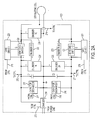
- Fig. 1 is an illustrative component diagram of a controllable pulse parameter transcranial magnetic stimulation system, according to some embodiments of the disclosed subject matter.
- the disclosed subject matter provides, among other things, a controllable pulse parameter transcranial magnetic stimulation (cTMS) system that induces approximately rectangular electric field pulses in an organ of a body, such as a human brain for example.
- cTMS controllable pulse parameter transcranial magnetic stimulation
- the amplitude, pulse width, and degree of bidirectionality of the induced electric field pulses are adjustable over a continuous range of values.
- the degree of bidirectionality is defined as the ratio of the positive phase amplitude to the negative phase amplitude of the induced electric field pulse.
- the induced electric field pulse can be varied from bipolar (i.e., equal amplitudes of the positive and negative phases) to predominantly unipolar (i.e., a large amplitude of one phase for one polarity and a small amplitude of the other phase for the opposite polarity).
- the cTMS system disclosed herein switches a stimulating coil between positive-voltage and negative-voltage energy storage capacitors or capacitor banks using high-power semiconductor devices. Controlling the pulse parameters facilitates enhancement of TMS as a probe of brain function and as a potential therapeutic intervention. Independent control over the pulse parameters (e.g., pulse width, pulse amplitude, degree of bidirectionality, pulse repetition frequency) facilitates defining dose-response relationships for neuronal populations and producing clinical and physiological effects. For example, dose-response relationships for specific neuronal populations can be defined, and selected clinical and physiological effects can be enhanced. Moreover, the cTMS system disclosed herein also enables high-frequency (> 1 Hz) repetitive TMS (rTMS) with predominantly unipolar induced electric fields.
- rTMS repetitive TMS
- the cTMS system 100 includes a power electronics housing 120, a positioning arm 130, a stimulating coil L, and a digital data processing device, such as control computer electronics 110.
- the control computer electronics 110 includes a control computer electronics housing 102 with analog-digital interface devices, a digital data processing device, and a storage device (e.g., a hard disk), a keyboard 104, a monitor 106, and a mouse 105 (or trackball), and/or other data entry devices.
- the power electronics circuitry in housing 120 includes cTMS system power electronics that supply current to the stimulating coil L, which can be positioned and held proximate to a patient's head by the positioning arm 130.
- the power electronics circuitry in the power electronics housing 120 is controlled by the control computer electronics 110.
- An operator, operating the control computer electronics 110 controls the power electronics in power electronics housing 120 to produce one or more adjustable current pulses that are passed through the stimulating coil L held by positioning arm 130.
- the stimulating coil L is positioned proximate to a patient's head.
- the adjustable current pulses that are passed through the stimulating coil L result in the stimulating coil L generating adjustable magnetic field pulses, which induce adjustable electric field pulses which, in turn, induce adjustable current pulses in the patient's brain.
- the power electronics housing 120 houses electronics used to drive the stimulating coil L.
- the electronics in the housing 120 include a charger 210, a first capacitor C1, a second capacitor C2, a first capacitor discharger 215, a second capacitor discharger 216, a first semiconductor switch Q1, a second semiconductor switch Q2, a first snubber circuit 222, a second snubber circuit 223, a third snubber circuit 224, a fourth snubber circuit 225, a fifth snubber circuit 226, a first gate drive 220, and a second gate drive 221.
- the control computer housing 102 houses a typical central processing unit (CPU) (not shown), and various standard printed circuit board slots (not shown). Inserted into one of the slots is a controller board 205 that provides control signals used to control the cTMS system 100, and is discussed in further detail below.
- CPU central processing unit
- controller board 205 that provides control signals used to control the cTMS system 100, and is discussed in further detail below.
- capacitor C1 and capacitor C2 are single capacitors. In another embodiment, capacitor C1 and capacitor C2 each represent a separate bank of capacitors. The capacitors in each separate bank are connected in parallel and/or in series with each other.
- the controllable pulse parameter transcranial magnetic stimulation circuit for driving the stimulation coil L includes energy storage capacitor (or bank of capacitors) C1, energy storage capacitor (or bank of capacitors) C2, controllable semiconductor switch Q1, controllable semiconductor switch Q2, the first and second gate drives 220, 221, and charger 210.
- the circuit of Fig. 3A additionally includes a diode D1 connected in anti-parallel with the controllable semiconductor switch Q1, and a diode D2 connected in anti-parallel with the controllable semiconductor switch Q2.
- an operator controls the cTMS system using the control computer electronics 110.
- the operator selects cTMS system operation with monophasic or biphasic magnetic pulses and a desired set of induced electric field pulse parameters such as pulse amplitude (A), width of positive pulse phase (PW + ), width of initial negative pulse phase (PW - can be chosen for the biphasic magnetic pulse only), ratio of negative to positive capacitor voltage (M), which determines the degree of bidirectionality, and the frequency of pulse repetition (f train ) via a graphical user interface (discussed below) executing on the control computer 102.
- the selected values are stored in the control computer 102.
- the controller board 205 is in communication with and controls the charger 210, the first gate drive 220, the second gate drive 221, and capacitor discharger 215 (which includes resistor 340 and normally closed relay 342) and capacitor discharger 216 (which includes resistor 344 and normally closed relay 346) via connections 273, 275, 276, 277, and 278, respectively.
- the controller board 205 is also in communication with, and receives data from, the energy storage capacitors C1 and C2, and the stimulating coil L via connections 272, 271, 274, respectively.
- the charger 210 charges the energy storage capacitor C1 to a positive voltage V C1 (set by the operator), and the energy storage capacitor C2 is charged to a negative voltage -V C2 (set by the operator).
- the charger transfers energy from a power line to the capacitors, and transfers energy between the two capacitors.
- the positive and negative capacitor voltages are independently selectable.
- Voltage V C1 is set based on the pulse amplitude (A) selected by the operator, and voltage V C2 is set equal to M* V C1 , where M is the ratio of negative to positive capacitor voltage selected by the operator.
- the stimulating coil L is connected to capacitors C1 and C2 via the semiconductor switches Q1 and Q2, and diodes D1 and D2, respectively.
- the controller board 205 also supplies separate sets of timing pulses with adjustable widths (set by the operator) to the first and second gate drives 220, 221.
- the first and second gate drives 220, 221 each use the timing pulses to produce separate sets of voltage pulses with adjustable widths.
- each semiconductor switch Q1 and Q2 includes a gate terminal 305 and 310, respectively.
- the gate terminals 305 and 310 are driven (i.e., clocked) by the voltage pulses supplied by the gate drives 220 and 221.
- the voltage pulses from controller board 205 are used to switch the semiconductor switches Q1 and Q2 to an on state or an off state.
- Anti-parallel connected diodes D1 and D2 transfer energy from the stimulating coil L back to capacitors C1 and C2, respectively.
- the semiconductor switch Q1 connects coil L to energy storage capacitor C1 for an interval of time equal to the pulse width of the voltage pulses received at the gate terminal 305 from the first gate drive 220, which causes the coil current I L to increase during this interval of time.
- semiconductor switch Q1 is turned off, the coil current commutates to capacitor C2 through diode D2, and the coil current starts to decrease until it reaches zero.
- turning switch Q1 on and off results in an approximately triangular positive coil current pulse, which induces an approximately triangular positive monophasic magnetic field pulse. This is discussed in further detail with respect to Fig. 4A .
- the semiconductor switch Q2 connects coil L to energy storage capacitor C2 for an interval of time equal to the pulse width of the voltage pulses received at the gate terminal 310 from the second gate drive 221, which causes the coil current I L to decrease (i.e., become more negative) during this interval of time.
- the coil current commutates to capacitor C1 through diode D1, and the coil current starts to increase (i.e., become more positive) until it reaches zero.
- turning switch Q2 on and off results in an approximately triangular negative coil current pulse, which produces an approximately triangular negative monophasic magnetic field pulse. This is discussed in further detail with respect to Fig. 4B .
- an adjustable biphasic magnetic pulse is produced.
- the approximately triangular magnetic field pulses with adjustable widths induce approximately rectangular electric field pulses in an organ of a body.
- the approximately rectangular electric field pulses induce approximately rectangular, adjustable-pulse-parameter current pulses in an organ of a body, such as a human brain, for example.
- the controller board 205 provides timing signals with microsecond resolution to control the semiconductor switches.
- the cTMS system uses timing of the turn-on and turn-off transitions of the control signals for both semiconductor switches Q1 and Q2 to provide accurate pulse waveform control.
- the controller board 205 is a PCI card from National Instruments (Austin, TX) with additional interface electronics that provides sub-microsecond timing signals. Additional interface electronics includes signal conditioning and isolation circuits such as optocouplers, fiber optic links, isolation transformers, attenuators, amplifiers, and filters, as required to connect the controller board 205 to the power electronics in the power electronics housing 120.
- the PCI card (controller board 205) resides in the control computer housing 102 that provides a GUI for interfacing and configuring the controller board 205.
- the control computer housing 102 also houses a mass storage device, such as a hard disk (not shown) for storing data.
- the GUI is implemented in LabVIEW software (available from National Instruments Corp.).
- the controller board software computes the corresponding capacitor voltages (V C1 , V C2 ) and switch timing.
- the controller board 205 then sends the capacitor voltage commands to the charger 210, capacitor dischargers 215, 216, and the switch timing signals to the gate drives 220, 221.
- the controller board 205 also samples V C1 , V C2 , and I L (via connections 271, 272, 274) to monitor circuit operation, and inhibits or prevents coil currents from exceeding specifications.
- the controllable semiconductor switches Q1 and Q2 should be able to withstand the peak coil current and the peak voltages appearing across their terminals at the peak pulse repetition frequency.
- the switches Q1 and Q2 should also have turn-on and turn-off times of no more than a few microseconds.
- the maximum voltage of the semiconductor switches Q1 and Q2 is ideally V C1 + V C2 .
- the switch voltage can overshoot this value due to stray inductance and the finite turn-off and turn-on times of the semiconductor switches Q1 and Q2, and diodes D1 and D2. To address this issue, semiconductor devices with fast switching times should be used.
- insulated gate bipolar transistors IGBTs - shown in Fig. 3B and available from Powerex of Youngwood, PA
- GBTs insulated gate bipolar transistors
- GT0s gate-turn-off thyristors
- IGCTs integrated gate-commutated thyristors
- Both of these devices can sustain pulse currents of thousands of amperes at voltages of a few kilovolts while turning on and off in a few microseconds.
- these devices can turn off while the coil current is not zero, they are used with the snubber circuits 222, 223, 224, 225, 226 (discussed in detail below) which absorb the energy of the commutation transients, thus inhibiting and/or preventing voltage overshoots that exceed the voltage ratings of the semiconductor switches, and energy dissipation in the semiconductor switches, which occurs during switching.
- IGBTs can be both turned on and off from the gate terminal.
- IGBT modules with peak voltage/surge current ratings of 3300 Volts/12000 Amperes, 4500 Volts/6000 Amperes, 4500 Volts/9000 Amperes, and 6500 Volts/6000 Amperes, and switching times of about one microsecond, which can be used to implement a cTMS system.
- IGBT modules have an integrated ultra-fast reverse diode between the emitter and the collector (e.g., D1 and D2 in Fig. 3 ), which clamps the IGBT reverse voltage, and provides a free-wheeling path for the coil current I L .
- IGCTs behave like efficient SCRs when turning on and during conduction, and behave like IGBTs when turning off.
- the turn-on time for an IGCT is approximately 1 ⁇ s, but the turn-off time can be as long as 10 ⁇ s.
- IGCTs with integrated reverse diodes (e.g., D1 and D2) and gate drives (e.g., gate drive 220, 221) are available with ratings of 4500 Volts and 17000 Amperes surge current, providing for robustness of the design.
- the stimulating coil L is forced to commutate between the two energy storage capacitors C1 and C2 when the coil current is at its peak.
- Managing the forced commutation transient is a challenging aspect of implementing the cTMS system.
- the finite turn-off and turn-on times of the semiconductor switches Q1 and Q2, and the stray inductance in the capacitor banks C1 and C2, the switches Q1 and Q2, the diodes D1 and D2, and the wiring between them, can result in voltage overshoots that exceed the voltage ratings of the semiconductor switches, and switching power loss and heating in the semiconductor switches.
- the stray inductances are reduced and/or minimized by installing the semiconductor switches Q1 and Q2, the diodes D1 and D2, and the capacitor banks C1 and C2 as close together as allowed by the physical dimensions of the components, and interconnecting them with wires or bus bars arranged to minimize the area of the current loop. Still, stray inductance cannot be completely eliminated. For example, a typical capacitor bank series inductance of 150 nH with 7 kA current stores magnetic energy sufficient to produce a 27 kV spike on an IGBT switch with 10 nF collector capacitance, which would exceed the voltage rating of a 4500 V IGBT by 22500 V, resulting in potential damage to the IGBT.
- the snubber circuits 222, 223, 224, 225, 226 are used to slow down the transients, ameliorate power dissipation in the semiconductor switches Q1 and Q2, and provide paths for stray inductances to discharge in order to suppress the voltage overshoots.
- the snubber circuits 222, 223 each include a capacitor 312, 318 in series with a diode 314, 320 and resistor 316, 322, which are in parallel with each other.
- Snubber circuits 222, 223 each also include capacitors 326, 330.
- This configuration allows the stimulating coil current to flow through the snubber capacitor 312, 318 when the corresponding semiconductor switch Q1, Q2 is turning off, thus inhibiting and/or preventing voltage overshoots.
- the snubber capacitor 312, 318 should be large enough to hold the peak switch voltage below its rated limit. If the snubber capacitor 312, 318 is too large, switching losses are increased.
- Snubber circuit 224 includes capacitor 324
- snubber circuit 225 includes capacitor 328
- snubber circuit 226 includes capacitor 332 and resistor 334.
- Snubber circuits 222 and 223 can include the circuit embodiments shown in Figs. 3D, 3E and/or 3F.
- Snubber circuits 224, 225, and 226 can include the circuit embodiments shown in Figs. 3D and/or 3E.
- the gate drives 220, 221 serve to drive (clock) the semiconductor switches Q1 and Q2 to an on state or an off state. As previously discussed, the gate drives 220, 221 receive timing signals from the controller board 205, and apply gate voltages to the gates 305, 310.
- Some high-power switches, such as IGCTs, are manufactured with an integrated gate drive unit. IGBTs typically require a separate external gate drive. For high-power IGBTs, 10-20 ⁇ C is delivered to the gate to raise the gate-emitter voltage to 15-20 Volts to turn on the device. To switch the gate in about 1 ⁇ s, IGBT gate drives need an output impedance of a few ohms, and provide peak currents of a few Amperes.
- the gate drives 220, 221 incorporate short-circuit protection which prevents the switch from turning on if a short circuit is detected between the collector and emitter terminals (in IGBTs) or the anode and cathode terminals (in GTOs and IGCTs), which improves the fault tolerance and safety of the cTMS system.
- the pulse width control parameters, PW+ and PW" are limited by the discharge of C1 and C2, respectively.
- the energy storage capacitors C1 and C2 in most embodiments disclosed herein, have capacitances in the range of 300 to 800 ⁇ F, and 1000 to 3000 ⁇ F, respectively. These capacitance values can be accomplished with single pulse capacitors or with banks of parallel and/or series connected pulse capacitors.
- Suitable capacitor technologies for implementation of C1 and C2 use oil, polypropylene, and/or polyester dielectrics.
- C1 is implemented using two parallel 185 ⁇ F, 3kV oil-filled pulse capacitors (e.g., General Atomics model 39504)
- C2 is implemented using two parallel 750 ⁇ F, 1 kV oil-filled pulse capacitors (e.g., General Atomics model 310DM475).
- the maximum C1 voltage V C1 is 2,800 V
- the minimum (maximum negative) C2 voltage -V C2 is 900 V.
- the capacitor charger 210 for the cTMS system supplies energy to both the capacitors C1 and C2 at two independently controlled DC voltages, V C1 and V C2 , respectively.
- the capacitor charger 210 also transfers energy from capacitor C2 to capacitor C1 to recover energy accumulated on capacitor C2 after a monophasic positive current pulse in coil L, corresponding to a positive monophasic magnetic field pulse.
- the capacitor charger 210 also transfers energy from capacitor C1 to capacitor C2 to recover energy accumulated on capacitor C1 after a monophasic negative current pulse in coil L, corresponding to a negative monophasic magnetic field pulse.
- a charging unit such as the Magstim Super Charger (available from The Magstim Corp., Whitland, UK) is used to charge the positive capacitor C1.
- a bidirectional inverting DC/DC power supply is used to transfer energy between capacitor C1 and capacitor C2 so that V C2 is maintained at a set level.
- Capacitor dischargers 215, 216 which constitute a resistor and a normally closed relay connected in series, are included and activated when the energy stored in capacitors C1 and C2 has to be reduced, such as when the pulse amplitude setting A is decreased by the operator, or when the energy stored in capacitors C1 and C2 has to be completely dissipated, such as when the cTMS system is shutdown, power is lost, or a system fault is detected by the controller.
- a stimulating coil L known in the art is used with the cTMS system. Both air core and ferromagnetic core coils can be used with the cTMS system.
- a coil connector compatible with Magstim 200 coils is used to connect the stimulating coil L to the cTMS circuitry.
- a Magstim 16.4 pH 70 mm double stimulating coil (commonly referred to in the art as a figure-of-8) is used.
- TMS systems operate at very high capacitor voltages (up to 3 kV) and peak coil currents (up to 10 kA).
- the cTMS system employs maximum positive and negative capacitor voltages of 2800 Volts and - 900 Volts, respectively, and a peak coil current of 7 kA.
- the currents, voltages, and pulse widths applied to the energy storage capacitors C1 and C2, stimulating coil L, coil cable and connector, and internal wiring in the cTMS system typically do not exceed the currents, voltages, and pulse widths in conventional TMS systems.
- the cTMS system power consumption in rTMS operation typically does not exceed that of existing TMS systems, since commensurate pulse energies and pulse train frequencies are used. Further, given the higher electrical efficiency of triangular magnetic pulses, the peak values of the pulse parameters could be reduced in comparison with available stimulators. Thus, existing solutions for these system components can be used in the cTMS system.
- the cTMS system induces approximately rectangular current pulses in the targeted body organ.
- Figs. 4A and 4B in one embodiment, under the conditions specified above, graphs of positive and negative monophasic magnetic field pulses generated using the controllable pulse parameter transcranial magnetic stimulation circuit are shown. For this illustration, the ratio of the voltage across the capacitor C1 to the voltage across the capacitor C2 (V C1 :V C2 ) is assumed to be 5:1.
- Fig. 4A depicts the generation of a positive magnetic field pulse 405, which is proportional to the current in the coil L.
- rise time t rise which is set by the operator by choosing when to turn Q1 on and off, switch Q1 is switched to an off state forcing the current I L in the stimulating coil L to commutate to capacitor C2 via the diode D2. While diode D2 is on, switch Q2 can be either on or off (referred to as a "don't care state" of the switch, and indicated with "x" symbols in the switch state waveforms).
- the stimulating coil current I L starts to decrease at a rate of - V C2 /(inductance of coil L) as shown by waveform 417 in plot 415.
- Fig. 4B depicts the generation of a negative magnetic field pulse, which is proportional to the current in the coil L as previously described.
- rise time t rise which is chosen by the operator, switch Q2 is switched to an off state forcing the current I L in the stimulating coil L to commutate to capacitor C1 via the diode D1.
- switch Q1 can be either on or off (referred to as a "don't care state" of the switch, and indicated with “x” symbols in the switch state waveforms). Since a positive voltage V C1 is now applied across the stimulating coil L, the stimulating coil current I L starts to increase at a rate of V C1 /(inductance of coil L) as shown by waveform 428 in plot 430.
- the energy exchange between the storage capacitors C1 and C2 is implemented using charger circuit 210 to transfer energy from capacitor C2 to C1, or from capacitor C1 to C2 between pulses.
- the energy exchange between the storage capacitors C1 and C2 is implemented by having a negative magnetic pulse precede a positive magnetic pulse. The energy from the storage capacitor C1 at the beginning of the pulse is returned to the storage capacitor C1 by the end of the pulse.
- illustrative monophasic waveforms of a magnetic field pulse (B) 505, an electric field (E) 510, and a neuronal membrane voltage (V m ) 515, induced in the brain by the controllable pulse parameter transcranial magnetic stimulation system are shown.
- the stimulating coil L is positioned proximate to a patient's head. Adjustable current pulses are passed through the stimulating coil L and cause the stimulating coil L to generate adjustable magnetic field pulses.
- the adjustable magnetic field pulses induce adjustable electric field pulses which, in turn, induce adjustable current pulses in the patient's brain.
- the induced adjustable current pulses in the patient's brain result in voltage change on the neuronal membrane that can be measured.
- the waveforms shown in Fig. 5A are produced by the current I L (plot 405) in the stimulating coil L shown in Fig. 4A .
- the magnetic field B (plot 505) is proportional to the current I L in the stimulating coil L, and thus also has a triangular shape.
- the induced electric field E (plot 510) is proportional to the magnetic field rate of change (dB/dt), and correspondingly has a rectangular shape, rather than the cosine shape of existing TMS systems.
- Different rising and falling slopes of the magnetic field B (plot 505) result in different magnitudes of the positive and negative phases of the induced electric field E (plot 510), respectively.
- the rate of change of the coil current (dIddt) and, therefore, the rate of change of the magnetic field (dB/dt) is proportional to the voltage across the coil L.
- the voltage across the coil L is equal to the voltage of the capacitor to which the coil is connected. Therefore, the ratio of peak positive to negative electric field E is V C1 :V C2 . This is true in general, even when the circuit non-idealities are considered.
- the neuronal membrane voltage (V m ) follows a decaying exponential curve characterized by the membrane time constant, as shown by plot 515. If the neuronal membrane is depolarized (i.e., made more positive) by more than approximately 15 mV relative to its resting potential (-60 to -70 mV), the neuron is likely to produce an action potential (i.e., to fire).
- illustrative waveforms of a biphasic magnetic field (B) 520, and the associated electric field (E) 525 and neuronal membrane voltage (V m ) 530 induced in the brain by the controllable pulse parameter transcranial magnetic stimulation system are shown.
- the magnetic field B of plot 520 is biphasic with symmetric positive and negative phases
- the induced electric field (plot 525) has a large positive amplitude and a comparatively small negative amplitude, since the rate of change of the rising magnetic field is much larger than the rate of change of the falling magnetic field.
- the depolarization amplitude (as the neuronal membrane is made more positive) is larger than the hyperpolarization amplitude (as the neuronal membrane is made more negative).
- This example demonstrates how the cTMS system can produce predominantly unipolar electric field pulses and neuronal membrane voltage changes with biphasic magnetic pulses.
- conventional sinusoidal biphasic magnetic pulses induce electric fields and neuronal membrane voltage changes that are bipolar (i.e., have approximately equal amplitudes of the positive and negative phases of the electric pulse).
- Biphasic magnetic pulses are more electrically efficient and produce less coil heating than monophasic magnetic pulses.
- TMS biphasic magnetic pulses can be used inside a magnetic resonance imaging (MRI) scanner, since the torque on the wire loops of the stimulating coil L in the strong magnetic field of the scanner averages to approximately zero.
- monophasic pulses cannot be used in an MRI scanner, since the average toque on the coil loops is non-zero, resulting in high mechanical stress in the coil that can damage the coil.
- A induced positive electric field amplitude
- illustrative waveforms of approximately rectangular, predominantly unipolar current pulses with adjustable pulse width are shown. Control over the pulse width (PW + ) of the induced electric field pulse is accomplished by controlling the on and off timing of the semiconductor switches Q1 and Q2.
- illustrative waveforms depicting user-adjustable degree of bidirectionality of approximately rectangular electric field pulses are shown. Control over the degree of bidirectionality is accomplished by adjustment of the voltages of energy storage capacitors C1 and C2 relative to each other.
- Fig. 9 shows an illustrative waveform of rTMS with a predominantly unipolar induced electric field.
- Computer simulations of a representative implementation of the cTMS system ( Fig. 10 ) indicate that the cTMS pulses can induce membrane depolarization and hyperpolarization equal to that of commercial monophasic stimulators at only 16-18% of the power dissipation. This results in a reduction of power supply demands, heating, noise, and component size, and enables the cTMS system to produce high-frequency rTMS with predominately unipolar induced electric fields.
- the cTMS system described in the disclosed subject matter was simulated and compared to existing TMS systems.
- a schematic of the cTMS simulation circuit is shown in Fig. 10 .
- a set of pulse performance metrics, i.e. performance figures, used to evaluate the efficiency of cTMS pulses compared to conventional pulse configurations of commercial TMS systems is shown in Fig. 11 .
- the values were derived from computer simulations using PSIM circuit simulation software (available from Powersim Inc.) and the simulation circuit shown in Fig. 10 .
- snubber circuits 1001 and 1002 are added across the semiconductor devices Q1 and Q2, snubber capacitors C1a and C1b are added across the capacitor bank C1, and snubber capacitors C2a and C2b are added across capacitor bank C2 to handle transient energy.
- Waveforms showing the coil current I L , peak induced electric field (E), and estimated neuronal membrane voltage change (dV m ) corresponding to the cTMS configuration shown in Fig. 10 are shown in Figs. 12A, 12B, and 12C , respectively.
- the total energy loss per pulse and the load integral are recalculated for an iron core coil, as indicated in Fig. 11 .
- the iron core proportionally increases the efficiency of all pulse configurations, and can be used with the cTMS system to improve efficiency.
- Four representative cTMS pulse configurations are simulated (see columns cTMS1-cTMS4 of Fig. 11 ).
- Fig. 11 shows that the cTMS system can produce predominantly unipolar neuronal membrane potential change with both monophasic (cTMS1) and biphasic (cTMS2- TMS4) magnetic field pulses.
- cTMS1 and cTMS2- TMS4 monophasic
- the cTMS2 pulse configuration yields a membrane hyperpolarization/depolarization ratio of 0.27, which is comparable to that of the Magstim 200 and MagPro X100 (monophasic mode), while dissipating only 16% and 18% of the energy, respectively.
- coil heating proportional to the load integral I L2 dt
- cTMS is able to achieve a total energy dissipation AW C comparable to efficient biphasic systems, such as the Neuronetics 2100, with 8-59% less coil heating (load integral) while adding the previously unavailable functionalities of control over the induced electric field pulse width, degree of bidirectionality, approximately rectangular shape, and predominantly unipolar electric field pulses.
- load integral the coil heating decreases dramatically, while the total energy dissipation increases slightly.
- the cTMS system is particularly well suited to generate high-frequency trains of predominantly unipolar electric field pulses.
- the unipolar rTMS power dissipation and coil heating of cTMS can be compared to that of conventional monophasic stimulators.
- the cTMS2 configuration is 5-6 times more efficient and has about three times less coil heating than the Magstim 200 and MagPro X100 while producing the same neuronal depolarization and comparable hyperpolarization/depolarization ratio.
- cTMS energy dissipation and coil heating can be further reduced to about 65 and 20 W, respectively. Therefore, with its substantially lower power dissipation and coil heating, the cTMS system can enable rTMS with predominantly unipolar electric field pulses. Recent research has indicated that rTMS with predominantly unipolar electric field pulses may have a stronger modulating effect on brain function, and, therefore, could be a more effective therapeutic intervention.
- cTMS controllable pulse parameter transcranial magnetic stimulation
- the cTMS system includes a cTMS circuit 1320 for driving a stimulating coil L.
- the cTMS circuit 1320 includes energy storage capacitor (or bank of capacitors) C1, controllable semiconductor switch Q1, a gate drive 1302, charger 1310, capacitor discharger 1322, diode D1, and resistor R1.
- the cTMS system further includes a digital data processing device, such as control computer system 102a, which includes a controller board 1305.
- the semiconductor switch Q1 is implemented with an IGBT, which unlike an SCR, can be turned off from a gate terminal 1304. Further, the diode D1 and the energy dissipation resistor R1 are connected across the TMS coil L, to provide a discharge path for the coil current when Q1 is turned off.
- the energy storage capacitor C1 is larger than those used in conventional TMS stimulators to provide a wider range of pulse width control and approximately rectangular induced electric field pulses.
- the cTMS circuit 1320 shown in Fig. 13A is controlled by the controller board 1305 shown in Fig. 13B , which resides in the control computer 102a.
- the controller board 1305 the operator specifies the voltage of capacitor C1, which determines the amplitude of the induced electric field.
- the operator also specifies the on time and the off time of switch Q1, which determine the pulse timing and the pulse width (PW + ).
- a schematic diagram of the cTMS circuit is shown. Stray inductance in the critical high-current paths of the circuit can cause power loss and voltage spikes during turn-off of switch Q1, which can cause component damage, as previously discussed. Therefore, the wiring and component locations in the cTMS circuit are arranged to reduce and/or minimize the stray inductance. However, stray inductances cannot be completely eliminated. Therefore, the cTMS circuit includes a number of snubber components. The snubber components assist the coil current commutation between the switch Q1 and the diode D1 and inhibits and/or prevents voltage overshoots and energy dissipation in the semiconductor switch Q1.
- a snubber capacitor or combination of capacitors C5 is mounted between the collector terminal of switch Q1 and the anode terminal of diode D1 to prevent the collector voltage from spiking during switch Q1 turn-off as a result of parasitic inductance of the capacitor bank C1 and the connecting wires.
- a capacitor C3 is mounted between the collector and emitter terminals of the switch Q1 to suppress high-voltage spikes across the terminals of switch Q1.
- the energy storage bank of capacitors C1 comprises six 118 ⁇ F (average measured value) oil-filled pulse capacitors.
- the bank of capacitors C1 is charged by a Magstim Booster Module Plus (The Magstim Co., Whitland, UK) and a Magstim capacitor voltage control circuit.
- the semiconductor switch Q1 is a 4500 Volt / 600 Amp (direct current rating) IGBT module from Powerex, Inc. (Youngwood, PA).
- the IGBT (switch Q1) is controlled with a high-voltage optically-isolated gate drive 1302 by Applied Power Systems, Inc. (Hicksville, NY).
- the controller board 1305 sends triggering pulses to the gate drive 1302. As previously described, the pulse width is set by the operator.
- the diode D1 is implemented with two series-connected, fast 1800 Volt / 102 Amp (direct current rating) diodes by Semikron GmbH (Nuremberg, Germany).
- the snubber capacitors C3-05 are high-voltage, high-current polypropylene film and paper film/foil capacitors.
- the snubber diode D2 includes three series-connected fast-recovery 1200 Volt / 60 Amp (direct current rating) diodes from International Rectifier (E1 Segundo, CA).
- the stimulating coil L is a custom-made Magstim 5.5 cm mean diameter round coil with an inductance of 16 ⁇ H.
- the cTMS circuit of Fig. 14 was tested with capacitor voltages of up to 1650 Volts, and peak coil currents of up to 7 kA.
- the peak intensity (i.e. amplitude of the electric field) of the cTMS system is equal to that of commercial Magstim Rapid stimulators. Unlike conventional stimulators, however, the cTMS system of the disclosed subject matter allows pulse width control with a range between 5 ⁇ s and 160 ⁇ s.
- the electric field induced by the cTMS system was estimated with a single-turn 5 cm diameter search coil placed two centimeters from the face of the cTMS coil L.
- the search coil was connected to a digitizing oscilloscope as well as to a first-order low-pass filter with 150 ⁇ s time constant, which outputs a scaled estimate of the neuronal membrane voltage waveform.
- the waveforms show six different pulse widths (i.e., 20, 40, 60, 80, 100, and 120 ⁇ s). It can be seen in Fig. 15B that the induced pulses, which are proportional to the electric field, have approximately rectangular shape, especially for brief pulses (e.g., 20 ⁇ s pulse).
- the above described cTMS implementation can be used to compare the intrinsic efficiency of rectangular unipolar electric field pulses versus conventional unipolar cosine pulses.
- the cTMS implementation was reconfigured to use a smaller capacitor and switch Q1 was kept on until the coil current decayed to zero.
- the comparison of rectangular pulses used the same initial capacitor voltage, and the cTMS pulse width was adjusted to achieve the same estimated neuronal depolarization.
- the corresponding rectangular pulses dissipated 20 and 28 % less energy, respectively.
- the cTMS circuit of Fig. 14 does not recycle pulse energy (pulse energy is dissipated in resistor R1 in Fig. 14 ), so this gain in efficiency comes solely from the rectangular pulse shape. With energy recycling, which is implemented in the circuit in Fig. 2 and Fig. 3 , efficiency will be even higher, as discussed above.
- Fig. 16 is shown an active snubber circuit connected in parallel with a magnetic stimulation coil L.
- the active snubber circuit can be used in any of the disclosed embodiments and others as illustrated in Fig. 16 .
- it can be used as the snubber circuit 226 in the embodiment of Fig. 2A .
- the active snubber circuit of Fig. 16 may include a non-inductive resistor Rsnub and at least two current-unidirectional switches (switch) as shown in Fig. 17 .
- the value of the non-inductive resistor Rsnub may be chosen to provide critically damped, or overdamped, response of the resonance between the coil L inductance and the capacitance of the pulse generator switching node, i.e., the capacitance that appears in parallel with the coil L when the coil is disconnected from the energy storage capacitors C1 and C2.
- This switching node capacitance typically results from the capacitance of snubbers 222 and 223 and from the capacitance of switches Q1 and Q2 in Fig. 2A .
- CTRL1 when CTRL1 is activated, current in a first direction is permitted to be established in Rsnub and when CTRL2 is activated, current in a second, reverse, direction is permitted to be established in Rsnub.
- CTRL1 when an undesired resonance generates a positive voltage across coil L, for example after a pulse is generated by the pulse generator circuit (not shown), the activation of CTRL1 will cause dissipation of the energy in Rsnub.
- the CTRL1 can be activated at any time during a negative phase for the electric field pulse when the coil current is ramping down toward zero and as soon as the coil voltage becomes positive due to resonance, the active snubber will permit current to flow through Rsnub and dissipate the energy.
- CTRL2 when CTRL2 is activated, current in the second direction is permitted to be established in Rsnub.
- the activation of CTRL2 will cause dissipation of the energy in Rsnub.
- the CTRL2 can be activated at any time during a positive phase of the electric field pulse when the coil current is ramping up toward zero and as soon as the coil voltage becomes negative due to resonance, the active snubber will permit current to flow through Rsnub and dissipate the energy.
- Figs. 18A-18E Different circuit embodiments for the switches included in the active snubber circuit of Fig. 17 are shown in Figs. 18A-18E .
- the switches can be implemented, for example, with IGTB (QS 1 , QS 2 ) and diode (DS 1 , DS 2 ) combinations, as shown in Figs. 18A-18B , and/or SCRs (QS 1 , QS 2 ), as shown in Fig. 18C , and/or MOSFET (QS 1 , QS 2 ) and diode (DS 1 , DS 2 ) combinations, as shown in Figs. 18D-18-E .
- CTRL1 and CTRL2 signals are generated by a controller similar to that described with regard to the embodiment of Fig. 2B , modified by providing appropriate control signals for CTRL1 and CTRL2.
- Also illustrated in Figs. 18A-18E are gate drivers, as indicated at GDS, if and as appropriate for the type of switch employed.
- the Q1, Q2 switch functions can also be implemented with components with lower voltage rating than the peak value of the voltage across the coil L by connecting a plurality n of switches (SW1 - SWn) in series, as shown in Fig. 19 .
- a resistor-capacitor voltage divider ladder (R div - C div ) including n resistors R div and n capacitors C div can be installed to force equal voltage drops on all n switch stages (SW1 - SWn).
- Rdiv can also be implemented with non-linear resistance elements, such as transient voltage suppressor (TVS) diodes.
- the control signals CTRL1 and CTRL2 are applied to the same effect as described above.
- each of SW1 can assume any of the configurations of Figs. 18A-18E or others.
- Figs. 20 and 21 illustrate activating a positive and a negative current conducting active snubber switch, respectively.
- a TMS pulse ends with a negative voltage phase (voltage V L applied to the coil L of Fig. 16 or similarly in other embodiments)
- the positive-current conducting snubber switch is activated by the controller (CTRL1 - ON) anytime during the voltage negative phase ( Fig. 20 ).
- CTRL1 - ON anytime during the voltage negative phase ( Fig. 20 ).
- the negative-current conducting snubber switch is activated by the controller (CTRL2 - ON) anytime during the V L positive phase ( Fig. 21 ).
- CTRL2 - ON the negative-current conducting snubber switch
- V L goes negative after the end of the positive phase, due to resonance of the coil L with the capacitance of the pulse generator switching node, current will start to flow in the active snubber.
- the energy in the coil L and in the capacitance of the pulse generator switching node will be dissipated in Rsnub.
- the snubber can be used for the control of transients in mono-phasic pulses or any other pulse sequences with appropriate configurations.
- a single control signal and switch may be used to control transients of a single polarity.
- Rsnub is described above as critically, or over damped, it is possible for it to be under damped. In the case of underdamping, oscillating may be tolerated or additional switching cycles may be provided to pass current through Rsnub in both directions during a parasitic oscillation event.
- the controllable pulse parameter transcranial stimulation circuit for driving the stimulation coil L includes energy storage capacitor (or bank of capacitors connected in series and/or parallel) C1, energy storage capacitor (or bank of capacitors connected in series and/or parallel) C2, four (4) controllable current-unidirectional semiconductor switches Q1-Q4, (Q1 and Q2 connected to C1 and Q3 and Q4 connected to C2), four (4) gate drives GD1-GD4, controlled by the system controller, for turning switches Q1-Q4, on and off, respectively, and a capacitor charger/discharger (shown connected to a power source such as voltage mains).
- the circuit additionally includes four (4) diodes D1-D4 connected in anti-parallel with respective controllable semiconductor switches Q1-Q4, as well as snubber circuits SN 1 -SN 8 . Note that any and all of the snubber circuits SN 1 -SN 8 is optional and provided as required for controlling transients and reducing switching losses as desired.
- an operator may control the cTMS system using control computer electronics 110, shown in Fig.1 .
- the operator may select cTMS system operation with monophasic magnetic pulses and a desired set of induced electric field pulse parameters, such as the pulse amplitude (A), width of positive pulse phase (PW + ), and the frequency of pulse repetition via a graphical user interface.
- a desired set of induced electric field pulse parameters such as the pulse amplitude (A), width of positive pulse phase (PW + ), and the frequency of pulse repetition via a graphical user interface.
- the controller board is in communication with and controls the charger/discharger, and also receives data from the energy storage capacitors C1 and C2, and the stimulating coil L.
- the charger/discharger may charge the energy storage capacitor C1 to a positive voltage V C1 (set by the operator), and the energy storage capacitor C2 also to a positive voltage V C2 (set by the operator). This is in contrast to the embodiments described above with reference to Figs. 2A and 3A .
- the charger/discharger may charge the capacitors from the mains we well as transfer energy between the two capacitors C1 and C2.
- the charger/discharger can also dissipate energy from C1 to C2, for example in the form of heat.
- the positive capacitor voltages V C1 and V C2 are independently selectable via the controller and implemented through the charger/discharger.
- the stimulating coil L is connected to capacitor C1 via semiconductor switches Q1 and Q2 and diodes D1 and D2, and is connected to capacitor C2 via semiconductor switches Q3 and Q4 and diodes D3 and D4.
- the controller supplies separate sets of timing pulses with adjustable widths (set by the operator) to the first, second, third and fourth gate drives (GD 1 - GD 4 ), which use the timing pulses to produce separate sets of voltage pulses with adjustable widths.
- the voltage pulses from the controller board are used to switch the semiconductor switches Q1-Q4 to an on or an off state, and the anti-parallel connected diodes D1-D4 conduct current depending on the state of switches Q1-Q4 and the coil current L.
- the semiconductor switches Q1-Q4 and diodes D1-D4 are connected to the stimulation coil L in such a way as to be able to apply to a first terminal Vx1 of the coil L a voltage V C1 or 0, and the second terminal Vx2 to a voltage V C2 or 0.
- the coil voltage V L could have any of the following values applied across it (reference polarity as indicated in Fig. 22 being positive on the left and negative on the right): 0, V C1 , -V C2 , or V C1 - V C2 .
- the switches Q1-Q4 are turned on and off by the controller so that V L can assume the desired value.
- Q1 and Q4 may be turned on and Q2 and Q3 turned off.
- the coil L may be connected thusly for an interval of time equal to the pulse widths of voltage pulses received from gate drives GD 1 and GD 2 , which causes the coil current to increase during a first time interval.
- the coil current commutates to diodes D2 and D3 to capacitor C2 charging C2 and thereby recovering energy in C2.
- the coil current decreases until it is zero at a rate determined by V C2 .
- a negative pulse can be generated in a similar fashion by turning on (then off) switches Q2 and Q3 to create a negative current in L (applying a voltage - V C2 across coil L) and then switching off to obtain energy recovery in capacitor C1 via diodes D1 and D4.
- the magnetic field pulses induce approximately rectangular electric field pulses in an organ of a body, which in turn, induce approximately rectangular, adjustable pulse current pulses in an organ body.
- the exact shape of the magnetic field and electric field pulses is piecewise sinusoidal, resulting from the resonant ringing behavior between the coil L and capacitors C1 and C2.
- the values of L, C1, and C2 can be chosen so that the piecewise sinusoidal electric field pulse waveform is approximately rectangular in shape.
- turning on switch Q1 alone may cause a voltage of V C1 - V C2 to be applied across coil L (assuming V C1 is higher - If V C2 is higher Q3 may be closed).
- one of D1 or D2, respectively turns on and connects the other terminal of the coil L to C2 or C1, respectively.
- snubber circuits SN 1 -SN 8 can be implemented in the circuit to facilitate the turn off of the switches and to reduce the switching losses by taking over part of the switch current during the turn off of the corresponding switch, as well as to suppress ringing in the circuit during switching resulting from parasitic inductances and capacitances in the circuit.
- Snubber circuits SN 1 -SN 8 can take the form of any of the previously described snubber circuits, as appropriate.
- the maximum voltage difference between any two parts of the circuit is the higher of V C1 and V C2 .
- the circuit design may provide the advantage that the maximum voltage required to be withstood by the semiconductor switches Q1 and Q2 as well as D1 and D2 is only V C1 , and thus, their voltage rating need be no higher than V C1 plus a margin for derating and to accommodate transient voltage spikes.
- the maximum voltage required to be withstood by the semiconductor switches Q3 and Q4 as well as D3 and D4 is only V C2 , and thus, their voltage rating need be no higher than V C2 plus a margin for derating and to accommodate transient voltage spikes. Switches with lower voltage ratings are generally less costly, smaller, and have lower conduction and switching losses.
- both terminals Vx1 and Vx2 can be connected together by turning Q2 and Q4 on, which then prevents ringing of current in the coil L that would otherwise occur due to the snubber capacitance.
- a 16 ⁇ H stimulating coil L a Powerex CM800HB-66H or CM1200HC-66HH single IGBT module for switch (Q1/D1), a Powerex CM800HB-66H or CM 1200HC-66HH single IGBT module for switch (Q2/D2), a Powerex CM800HA-28H or CM1000HA-28H single IGBT module or (1/2) CM800DZ-34H or (1/2) CM1000DU-34NF dual IGBT module for switch (Q3/D3), and a Powerex CM800HA-28H or CM1000HA-28H single IGBT module or (1/2) CM800DZ-34H or (1/2) CM1000DU-34NF dual IGBT module for switch (Q4/D4) is used to induce approximately rectangular current pulses in the targeted body organ.
- the energy storage capacitors C1 and C2 have capacitances in the range of 370-740 ⁇ F and 1,500-3,000 ⁇ F, respectively. These capacitance values can be accomplished with single pulse capacitors or with banks of parallel and/or series connected pulse capacitors with polypropylene dielectrics or paper/oil dielectrics.
- the maximum setting of voltage V C1 is 2,800V and the maximum setting of voltage V C2 is 1,000 V.
- Snubber circuit SN 1 -SN 4 can each include a 0.25 ⁇ F capacitor in parallel with series combination of 0.5 ⁇ F capacitor and a 1 ⁇ resistor. Snubber circuits SN 5 -SN 8 can be omitted in this embodiment.
- the cTMS system disclosed herein enables an operator to adjust various pulse shape parameters (previously described in detail) of an electric field pulse induced in the brain of a patient.
- the values of these pulse shape parameters can be chosen based on which medical application is being implemented and/or a patient's physiological characteristics. Further, the capability to control pulse parameters enables a medical professional to study the contribution of pulse characteristics to observed physiological effects of an induced electric field pulse.
- the cTMS systems disclosed herein produce approximately rectangular induced electric field pulses, which are more energy efficient for neuronal stimulation than sinusoidal pulses produced by existing TMS systems, as previously described.
- the cTMS systems depicted in Figs. 2 and 3 also enable an operator to vary the degree of bidirectionality of the induced pulse over a continuous range from a predominantly unipolar to a bipolar electric field pulse.
- the cTMS systems disclosed herein have the potential for enabling diverse clinical and research applications.
- the cTMS systems can be used to determine strength-duration curves (i.e., the induced electric field pulse amplitude vs. the pulse width that produces threshold neuronal stimulation).
- Strength-duration curves can be used to estimate a neuronal membrane time constant, and can therefore be a useful tool for diagnosing and studying neurological disease.
- Strength-duration curves can also be used to optimize stimulation paradigms for different cortical regions, and activate selectively different neuronal types possessing different membrane time constants and responsivity to pulse shape characteristics.
- the capability to adjust the pulse shape in the cTMS system could enable optimization of the stimulus parameters for various applications.
- TMS with briefer, high-amplitude pulses requires less energy delivered to the stimulating coil, thereby increasing efficiency and decreasing heating.
- TMS and rTMS with brief (e.g., 20-50 ⁇ s) rectangular pulses are more energy efficient.
Applications Claiming Priority (3)
| Application Number | Priority Date | Filing Date | Title |
|---|---|---|---|
| US17959009P | 2009-05-19 | 2009-05-19 | |
| US22564409P | 2009-07-15 | 2009-07-15 | |
| EP10778324.3A EP2432547B1 (de) | 2009-05-19 | 2010-05-19 | Systeme zur induktion von elektrischen feldimpulsen auf ein körperorgan |
Related Parent Applications (1)
| Application Number | Title | Priority Date | Filing Date |
|---|---|---|---|
| EP10778324.3A Division EP2432547B1 (de) | 2009-05-19 | 2010-05-19 | Systeme zur induktion von elektrischen feldimpulsen auf ein körperorgan |
Publications (1)
| Publication Number | Publication Date |
|---|---|
| EP2907540A1 true EP2907540A1 (de) | 2015-08-19 |
Family
ID=43126492
Family Applications (2)
| Application Number | Title | Priority Date | Filing Date |
|---|---|---|---|
| EP14192737.6A Withdrawn EP2907540A1 (de) | 2009-05-19 | 2010-05-19 | Magnetisches Stimulationssystem |
| EP10778324.3A Active EP2432547B1 (de) | 2009-05-19 | 2010-05-19 | Systeme zur induktion von elektrischen feldimpulsen auf ein körperorgan |
Family Applications After (1)
| Application Number | Title | Priority Date | Filing Date |
|---|---|---|---|
| EP10778324.3A Active EP2432547B1 (de) | 2009-05-19 | 2010-05-19 | Systeme zur induktion von elektrischen feldimpulsen auf ein körperorgan |
Country Status (3)
| Country | Link |
|---|---|
| US (1) | US9345901B2 (de) |
| EP (2) | EP2907540A1 (de) |
| WO (1) | WO2010135425A1 (de) |
Cited By (1)
| Publication number | Priority date | Publication date | Assignee | Title |
|---|---|---|---|---|
| WO2023280332A1 (en) * | 2021-07-09 | 2023-01-12 | Deymed Diagnostic S.R.O. | Monophasic magnetic stimulator for transcranial magnetic stimulation |
Families Citing this family (55)
| Publication number | Priority date | Publication date | Assignee | Title |
|---|---|---|---|---|
| GB2486400B (en) * | 2010-11-20 | 2016-02-10 | Pulse Medical Technologies Ltd | Device for generating magnetic fields |
| DE102012013534B3 (de) | 2012-07-05 | 2013-09-19 | Tobias Sokolowski | Vorrichtung für repetitive Nervenstimulation zum Abbau von Fettgewebe mittels induktiver Magnetfelder |
| US10357144B2 (en) * | 2013-03-14 | 2019-07-23 | Given Imaging Ltd. | Method and circuit for muting electromagnetic interference during maneuvering of a device |
| DE102013211859B4 (de) * | 2013-06-21 | 2015-07-16 | Technische Universität München | Magnetstimulator zur Stimulation eines Gewebes durch ein Magnetfeld |
| CN105451631B (zh) | 2013-08-29 | 2018-05-18 | 基文影像公司 | 用于操纵线圈功率优化的系统和方法 |
| US20150080637A1 (en) * | 2013-09-16 | 2015-03-19 | The General Hospital Corporation | Microscopic magnetic coils for neural stimulation |
| DE202014004932U1 (de) | 2014-06-20 | 2014-09-01 | Stefan Goetz | Mechanische Anordnung einer Magnetspule und zugehörige elektronische Schaltung zur Unterbindung unerwünschter mechanischer Schwingungen |
| EP3157624A2 (de) | 2014-06-20 | 2017-04-26 | GOETZ, Stefan | Vorrichtung und verfahren zur geräuscharmen magnetischen neurostimulation |
| DE102014008820A1 (de) | 2014-06-20 | 2015-12-24 | Stefan Goetz | Vorrichtung und Verfahren zur geräuscharmen magnetischen Neurostimulation |
| GB2530475A (en) | 2014-06-20 | 2016-03-30 | Stefan M Goetz | Device and method for quiet magnetic neurostimulation |
| DE202014004930U1 (de) | 2014-06-20 | 2014-09-01 | Stefan Goetz | Magnetstimulationssystem zur Verringerung akustischer Emissionen durch Vermeidung des menschlichen Hörbereiches und Ausnutzung psychoakustischer Phänomene |
| US9919161B2 (en) | 2015-07-01 | 2018-03-20 | Btl Holdings Limited | Method of neural structure stimulation by magnetic field |
| US10124187B2 (en) | 2015-04-28 | 2018-11-13 | Btl Holdings Limited | Combination of radiofrequency and magnetic treatment methods |
| US11491342B2 (en) | 2015-07-01 | 2022-11-08 | Btl Medical Solutions A.S. | Magnetic stimulation methods and devices for therapeutic treatments |
| US9768607B2 (en) * | 2015-05-11 | 2017-09-19 | Infineon Technologies Ag | System and method for a multi-phase snubber circuit |
| US20170001030A1 (en) | 2015-07-01 | 2017-01-05 | Btl Holdings Limited | Magnetic stimulation device and methods |
| US10709894B2 (en) | 2015-07-01 | 2020-07-14 | Btl Medical Technologies S.R.O. | Aesthetic method of biological structure treatment by magnetic field |
| US9937358B2 (en) | 2015-07-01 | 2018-04-10 | Btl Holdings Limited | Aesthetic methods of biological structure treatment by magnetic field |
| US9974519B1 (en) | 2015-07-01 | 2018-05-22 | Btl Holdings Limited | Aesthetic method of biologoical structure treatment by magnetic field |
| US10695575B1 (en) | 2016-05-10 | 2020-06-30 | Btl Medical Technologies S.R.O. | Aesthetic method of biological structure treatment by magnetic field |
| US10493293B2 (en) | 2015-07-01 | 2019-12-03 | Btl Medical Technologies S.R.O. | Aesthetic method of biological structure treatment by magnetic field |
| US10471269B1 (en) | 2015-07-01 | 2019-11-12 | Btl Medical Technologies S.R.O. | Aesthetic method of biological structure treatment by magnetic field |
| US10245439B1 (en) | 2015-07-01 | 2019-04-02 | Medical Technologies Cz A.S. | Aesthetic method of biological structure treatment by magnetic field |
| US10549110B1 (en) | 2015-07-01 | 2020-02-04 | Btl Medical Technologies S.R.O. | Aesthetic method of biological structure treatment by magnetic field |
| US20180001107A1 (en) | 2016-07-01 | 2018-01-04 | Btl Holdings Limited | Aesthetic method of biological structure treatment by magnetic field |
| US10569094B2 (en) | 2015-07-01 | 2020-02-25 | Btl Medical Technologies S.R.O. | Aesthetic method of biological structure treatment by magnetic field |
| US11266850B2 (en) | 2015-07-01 | 2022-03-08 | Btl Healthcare Technologies A.S. | High power time varying magnetic field therapy |
| US10478633B2 (en) | 2015-07-01 | 2019-11-19 | Btl Medical Technologies S.R.O. | Aesthetic method of biological structure treatment by magnetic field |
| US10695576B2 (en) | 2015-07-01 | 2020-06-30 | Btl Medical Technologies S.R.O. | Aesthetic method of biological structure treatment by magnetic field |
| US10478634B2 (en) | 2015-07-01 | 2019-11-19 | Btl Medical Technologies S.R.O. | Aesthetic method of biological structure treatment by magnetic field |
| US10821295B1 (en) | 2015-07-01 | 2020-11-03 | Btl Medical Technologies S.R.O. | Aesthetic method of biological structure treatment by magnetic field |
| US10549109B2 (en) | 2015-07-01 | 2020-02-04 | Btl Medical Technologies S.R.O. | Aesthetic method of biological structure treatment by magnetic field |
| US11253717B2 (en) | 2015-10-29 | 2022-02-22 | Btl Healthcare Technologies A.S. | Aesthetic method of biological structure treatment by magnetic field |
| US11247039B2 (en) | 2016-05-03 | 2022-02-15 | Btl Healthcare Technologies A.S. | Device including RF source of energy and vacuum system |
| US11464993B2 (en) | 2016-05-03 | 2022-10-11 | Btl Healthcare Technologies A.S. | Device including RF source of energy and vacuum system |
| US11534619B2 (en) | 2016-05-10 | 2022-12-27 | Btl Medical Solutions A.S. | Aesthetic method of biological structure treatment by magnetic field |
| US10583287B2 (en) | 2016-05-23 | 2020-03-10 | Btl Medical Technologies S.R.O. | Systems and methods for tissue treatment |
| US10556122B1 (en) | 2016-07-01 | 2020-02-11 | Btl Medical Technologies S.R.O. | Aesthetic method of biological structure treatment by magnetic field |
| CA3040164A1 (en) | 2016-10-16 | 2018-04-19 | Stimaire, Inc. | Wireless neural stimulator with injectable |
| FI129532B (en) * | 2017-04-03 | 2022-04-14 | Aalto Korkeakoulusaeaetioe | Control of transcranial magnetic stimulation |
| DE102017108084B4 (de) | 2017-04-13 | 2023-08-31 | Universität der Bundeswehr München | Pulsquelle und Verfahren für die magnetisch induktive Nervenreizung |
| US10230364B2 (en) * | 2017-04-26 | 2019-03-12 | Futurewei Technologies, Inc. | Hybrid power devices |
| WO2018225038A1 (en) * | 2017-06-08 | 2018-12-13 | Nexus Technologies, Inc. | Short-circuit protection for a power semiconductor device |
| KR102323560B1 (ko) | 2017-08-08 | 2021-11-08 | 삼성전자주식회사 | 전류의 피크 세기를 조절하도록 구성되는 회로를 포함하는 전자 장치 |
| EP3684463A4 (de) | 2017-09-19 | 2021-06-23 | Neuroenhancement Lab, LLC | Verfahren und vorrichtung für neuro-enhancement |
| US11717686B2 (en) | 2017-12-04 | 2023-08-08 | Neuroenhancement Lab, LLC | Method and apparatus for neuroenhancement to facilitate learning and performance |
| US11273283B2 (en) | 2017-12-31 | 2022-03-15 | Neuroenhancement Lab, LLC | Method and apparatus for neuroenhancement to enhance emotional response |
| US11364361B2 (en) | 2018-04-20 | 2022-06-21 | Neuroenhancement Lab, LLC | System and method for inducing sleep by transplanting mental states |
| WO2020056418A1 (en) | 2018-09-14 | 2020-03-19 | Neuroenhancement Lab, LLC | System and method of improving sleep |
| CN109331337B (zh) * | 2018-11-12 | 2022-03-11 | 吴军发 | 一种变幅值及变脉宽的对称脉冲波经颅刺激装置及方法 |
| MX2021012225A (es) | 2019-04-11 | 2022-12-05 | Btl Medical Solutions A S | Metodos y aparatos para el tratamiento estetico de estructuras biologicas mediante radiofrecuencia y energia magnetica. |
| US11878167B2 (en) | 2020-05-04 | 2024-01-23 | Btl Healthcare Technologies A.S. | Device and method for unattended treatment of a patient |
| MX2022013485A (es) | 2020-05-04 | 2022-11-30 | Btl Healthcare Tech A S | Dispositivo y metodo para el tratamiento sin atencion del paciente. |
| US11896816B2 (en) | 2021-11-03 | 2024-02-13 | Btl Healthcare Technologies A.S. | Device and method for unattended treatment of a patient |
| CN115313686A (zh) * | 2022-07-19 | 2022-11-08 | 中国人民解放军国防科技大学 | 一种正负充放电的重频脉冲磁场装置 |
Citations (2)
| Publication number | Priority date | Publication date | Assignee | Title |
|---|---|---|---|---|
| US5047005A (en) * | 1987-01-28 | 1991-09-10 | Cadwell Industries, Inc. | Method and apparatus for magnetically stimulating neurons |
| WO2007145838A2 (en) * | 2006-06-15 | 2007-12-21 | The Trustees Of Columbia University In The City Of New York | Systems and methods for inducing electric field pulses in a body organ |
Family Cites Families (33)
| Publication number | Priority date | Publication date | Assignee | Title |
|---|---|---|---|---|
| EP0039206B1 (de) | 1980-04-23 | 1984-10-10 | Inoue-Japax Research Incorporated | Gerät zur magnetischen Behandlung |
| JPS63198525A (ja) | 1987-02-12 | 1988-08-17 | 三菱電機株式会社 | 過電圧保護装置 |
| US5327854A (en) | 1992-07-31 | 1994-07-12 | Smith-Root, Inc. | Electric fish shocking devices using programmable output waveforms |
| US6117066A (en) | 1992-12-04 | 2000-09-12 | Somatics, Inc. | Prevention of seizure arising from medical magnetoictal non-convulsive stimulation therapy |
| US5813970A (en) | 1992-12-04 | 1998-09-29 | Somatics, Inc. | Medical magnetoictal therapy |
| US5769778A (en) | 1994-04-22 | 1998-06-23 | Somatics, Inc. | Medical magnetic non-convulsive stimulation therapy |
| US5707334A (en) | 1995-08-21 | 1998-01-13 | Young; Robert B. | Method of treating amygdala related transitory disorders |
| GB9808764D0 (en) | 1998-04-25 | 1998-06-24 | Magstim Co Ltd | Magnetic stimulators for neuro-muscular tissue |
| EP0958844A3 (de) | 1998-05-15 | 2000-08-09 | Siemens Aktiengesellschaft | Magnetstimulationsgerät |
| US6198958B1 (en) | 1998-06-11 | 2001-03-06 | Beth Israel Deaconess Medical Center, Inc. | Method and apparatus for monitoring a magnetic resonance image during transcranial magnetic stimulation |
| US7231254B2 (en) | 1998-08-05 | 2007-06-12 | Bioneuronics Corporation | Closed-loop feedback-driven neuromodulation |
| US7277758B2 (en) | 1998-08-05 | 2007-10-02 | Neurovista Corporation | Methods and systems for predicting future symptomatology in a patient suffering from a neurological or psychiatric disorder |
| AUPQ404899A0 (en) | 1999-11-16 | 1999-12-09 | Price, Gregory Walter Dr | Aprocess of interactive stimulation of the brain as a means of modifying the electroencephalogram so as to modify particular electrophysiological respon ses |
| US6402678B1 (en) | 2000-07-31 | 2002-06-11 | Neuralieve, Inc. | Means and method for the treatment of migraine headaches |
| US6591138B1 (en) | 2000-08-31 | 2003-07-08 | Neuropace, Inc. | Low frequency neurostimulator for the treatment of neurological disorders |
| AU2912902A (en) | 2000-10-20 | 2002-04-29 | Us Gov Health & Human Serv | Coil for magnetic stimulation and methods for using the same |
| WO2002062283A2 (en) * | 2001-02-08 | 2002-08-15 | Ramot University For Applied Research And Industrial Development Ltd. | Control of body electrical activity by magnetic fields |
| US6572528B2 (en) | 2001-04-20 | 2003-06-03 | Mclean Hospital Corporation | Magnetic field stimulation techniques |
| US8047979B2 (en) * | 2001-04-20 | 2011-11-01 | Mclean Hospital Corporation | Magnetic field treatment techniques |
| AU2002254777B2 (en) * | 2001-05-04 | 2005-02-03 | Board Of Regents, The University Of Texas System | Apparatus and methods for delivery of transcranial magnetic stimulation |
| DE10122426A1 (de) | 2001-05-09 | 2003-01-23 | Siemens Ag | Verfahren zum Betrieb eines Magnetresonanzgeräts und Magnetresonanzgerät zum Durchführen des Verfahrens |
| US6551233B2 (en) | 2001-08-08 | 2003-04-22 | R. B. Carr Engineering, Onc. | Magnetic stimulator power and control circuit |
| US6978179B1 (en) | 2002-02-27 | 2005-12-20 | Flagg Rodger H | Method and apparatus for magnetic brain wave stimulation |
| US7130203B2 (en) | 2002-04-30 | 2006-10-31 | Det International Holding Limited | Switching power supply with a snubber circuit |
| US6899667B2 (en) | 2002-10-21 | 2005-05-31 | Paul F. Becker | Method and apparatus for the treatment of physical and mental disorders with low frequency, low flux density magnetic fields |
| US7294101B2 (en) | 2002-12-21 | 2007-11-13 | Neuropace, Inc. | Means and methods for treating headaches |
| US7153256B2 (en) | 2003-03-07 | 2006-12-26 | Neuronetics, Inc. | Reducing discomfort caused by electrical stimulation |
| US7104947B2 (en) | 2003-11-17 | 2006-09-12 | Neuronetics, Inc. | Determining stimulation levels for transcranial magnetic stimulation |
| US7422555B2 (en) * | 2003-12-30 | 2008-09-09 | Jacob Zabara | Systems and methods for therapeutically treating neuro-psychiatric disorders and other illnesses |
| MX358779B (es) | 2004-04-26 | 2018-09-04 | Ivivi Health Sciences Llc | Aparato y método para la inducción de tratamiento electromagnético. |
| SE527820C2 (sv) * | 2004-09-03 | 2006-06-13 | Transunit Ab | Metod och koppling för eliminering av uppvärmningstid och störningar i en ventilator eller anestesimaskin |
| CN1879906A (zh) | 2005-06-15 | 2006-12-20 | 郑云峰 | 中枢神经系统磁刺激装置及其使用方法 |
| US20070282388A1 (en) * | 2006-06-01 | 2007-12-06 | Reuven Sandyk | Method and apparatus for treatment of amyotrophic lateral sclerosis patients |
-
2010
- 2010-05-19 US US13/321,073 patent/US9345901B2/en active Active
- 2010-05-19 WO PCT/US2010/035401 patent/WO2010135425A1/en active Application Filing
- 2010-05-19 EP EP14192737.6A patent/EP2907540A1/de not_active Withdrawn
- 2010-05-19 EP EP10778324.3A patent/EP2432547B1/de active Active
Patent Citations (2)
| Publication number | Priority date | Publication date | Assignee | Title |
|---|---|---|---|---|
| US5047005A (en) * | 1987-01-28 | 1991-09-10 | Cadwell Industries, Inc. | Method and apparatus for magnetically stimulating neurons |
| WO2007145838A2 (en) * | 2006-06-15 | 2007-12-21 | The Trustees Of Columbia University In The City Of New York | Systems and methods for inducing electric field pulses in a body organ |
Non-Patent Citations (5)
| Title |
|---|
| A. ANTAL; T. Z. KINCSES; M. A. NITSCHE; 0. BARTFAI; 1. DEMMER; M. SOMMER; W. PAULUS: "Pulse configuration-dependent effects of repetitive transcranial magnetic stimulation on visual perception", NEUROREPORT, vol. 13, no. T7, 2002, pages 2229 - 33 |
| M. SOMMER; N. LANG; F. TERGAU; W. PAULUS: "Neuronal tissue polarization induced by repetitive transcranial magnetic stimulation", NEUROREPORT, vol. 13, no. 6, 2002, pages 809 - 11 |
| MILAN M. JOVANOVIC ET AL: "Evaluation of active and passive snubber techniques for applications in power-factor-correction boost converters", SIXTH INTERNATIONAL CONFERENCE ON POWER SEMICONDUCTORS AND THEIR APPLICATIONS (ELECTRONICA '92), MUNCHEN, GERMANY, 11 November 1992 (1992-11-11), Munich, Germany, pages 105 - 115, XP055186144 * |
| N. ARAI; S. OKABE; T. FURUBAYASHI; Y. TERAO; K. YUASA; Y. UGAWA: "Comparison between short train, monophasic and biphasic repetitive transcranial magnetic stimulation (rTMS) of the human motor cortex", CLIN NEUROPHYSIOL, vol. 116, no. 3, 2005, pages 605 - 13, XP004766635, DOI: doi:10.1016/j.clinph.2004.09.020 |
| T. TINGS; N. LANG; F. TERGAU; W. PAULUS; M. SOMMER: "Orientation-specific fast rTMS maximizes corticospinal inhibition and facilitation", EXP BRAIN RES, vol. 164, no. 3, 2005, pages 323 - 33, XP019328920, DOI: doi:10.1007/s00221-005-2253-6 |
Cited By (1)
| Publication number | Priority date | Publication date | Assignee | Title |
|---|---|---|---|---|
| WO2023280332A1 (en) * | 2021-07-09 | 2023-01-12 | Deymed Diagnostic S.R.O. | Monophasic magnetic stimulator for transcranial magnetic stimulation |
Also Published As
| Publication number | Publication date |
|---|---|
| US9345901B2 (en) | 2016-05-24 |
| EP2432547A1 (de) | 2012-03-28 |
| EP2432547A4 (de) | 2013-03-27 |
| EP2432547B1 (de) | 2014-11-12 |
| US20120108883A1 (en) | 2012-05-03 |
| WO2010135425A1 (en) | 2010-11-25 |
Similar Documents
| Publication | Publication Date | Title |
|---|---|---|
| EP2432547B1 (de) | Systeme zur induktion von elektrischen feldimpulsen auf ein körperorgan | |
| EP2026871B1 (de) | System zur induktion von elektrischen feldimpulsen auf ein körperorgan | |
| US8545378B2 (en) | Systems and methods for inducing electric field pulses in a body organ | |
| Peterchev et al. | A transcranial magnetic stimulator inducing near-rectangular pulses with controllable pulse width (cTMS) | |
| Peterchev et al. | Repetitive transcranial magnetic stimulator with controllable pulse parameters | |
| Peterchev et al. | Controllable pulse parameter transcranial magnetic stimulator with enhanced circuit topology and pulse shaping | |
| US10173071B2 (en) | Medical successive magnetic pulse generation device | |
| KR100547265B1 (ko) | 변조 기능을 갖는 펄스 자기 자극 생성 장치 및 방법 | |
| US9180305B2 (en) | Systems and methods for controlling electric field pulse parameters using transcranial magnetic stimulation | |
| US5066272A (en) | Magnetic nerve stimulator | |
| US11666774B2 (en) | Pulse source and method for magnetically inductive nerve stimulation | |
| CA2689623A1 (en) | Drive circuit for magnetic stimulation | |
| US8157718B2 (en) | Electric circuit, having transformer which can function as a buffer inductor, and magnetic stimulator therewith | |
| Sorkhabi et al. | Programmable transcranial magnetic stimulation: A modulation approach for the generation of controllable magnetic stimuli | |
| Peterchev et al. | Repetitive transcranial magnetic stimulator with controllable pulse parameters (cTMS) | |
| Li et al. | Modular pulse synthesizer for transcranial magnetic stimulation with flexible user-defined pulse shaping and rapidly changing pulses in sequences | |
| Li et al. | Modular pulse synthesizer for transcranial magnetic stimulation with fully adjustable pulse shape and sequence | |
| Riehl | TMS stimulator design | |
| Peterchev | Circuit topology comparison and design analysis for controllable pulse parameter transcranial magnetic stimulators | |
| US20230108766A1 (en) | Generation of controllable magnetic stimuli | |
| Denison et al. | Generation of controllable magnetic stimuli | |
| CN212214384U (zh) | 一种新型双极性电磁激励系统 | |
| Li et al. | Transcranial Magnetic Stimulation Tech-nology with Freely Adjustable Pulse Shape and Sequence | |
| SCR | applications [9]. For example, the strength-duty curve | |
| CN111991699A (zh) | 一种以开关控制电路的电磁激励系统及方法 |
Legal Events
| Date | Code | Title | Description |
|---|---|---|---|
| PUAI | Public reference made under article 153(3) epc to a published international application that has entered the european phase |
Free format text: ORIGINAL CODE: 0009012 |
|
| AC | Divisional application: reference to earlier application |
Ref document number: 2432547 Country of ref document: EP Kind code of ref document: P |
|
| AK | Designated contracting states |
Kind code of ref document: A1 Designated state(s): AL AT BE BG CH CY CZ DE DK EE ES FI FR GB GR HR HU IE IS IT LI LT LU LV MC MK MT NL NO PL PT RO SE SI SK SM TR |
|
| STAA | Information on the status of an ep patent application or granted ep patent |
Free format text: STATUS: THE APPLICATION IS DEEMED TO BE WITHDRAWN |
|
| 18D | Application deemed to be withdrawn |
Effective date: 20160220 |