EP0033005A2 - Verbrauchbarer Messkopf für Tauchthermoelemente - Google Patents
Verbrauchbarer Messkopf für Tauchthermoelemente Download PDFInfo
- Publication number
- EP0033005A2 EP0033005A2 EP80108003A EP80108003A EP0033005A2 EP 0033005 A2 EP0033005 A2 EP 0033005A2 EP 80108003 A EP80108003 A EP 80108003A EP 80108003 A EP80108003 A EP 80108003A EP 0033005 A2 EP0033005 A2 EP 0033005A2
- Authority
- EP
- European Patent Office
- Prior art keywords
- measuring head
- shaped
- plate
- elements
- head according
- Prior art date
- Legal status (The legal status is an assumption and is not a legal conclusion. Google has not performed a legal analysis and makes no representation as to the accuracy of the status listed.)
- Granted
Links
Images
Classifications
-
- G—PHYSICS
- G01—MEASURING; TESTING
- G01K—MEASURING TEMPERATURE; MEASURING QUANTITY OF HEAT; THERMALLY-SENSITIVE ELEMENTS NOT OTHERWISE PROVIDED FOR
- G01K7/00—Measuring temperature based on the use of electric or magnetic elements directly sensitive to heat ; Power supply therefor, e.g. using thermoelectric elements
- G01K7/02—Measuring temperature based on the use of electric or magnetic elements directly sensitive to heat ; Power supply therefor, e.g. using thermoelectric elements using thermoelectric elements, e.g. thermocouples
- G01K7/023—Measuring temperature based on the use of electric or magnetic elements directly sensitive to heat ; Power supply therefor, e.g. using thermoelectric elements using thermoelectric elements, e.g. thermocouples provided with specially adapted connectors
-
- G—PHYSICS
- G01—MEASURING; TESTING
- G01K—MEASURING TEMPERATURE; MEASURING QUANTITY OF HEAT; THERMALLY-SENSITIVE ELEMENTS NOT OTHERWISE PROVIDED FOR
- G01K7/00—Measuring temperature based on the use of electric or magnetic elements directly sensitive to heat ; Power supply therefor, e.g. using thermoelectric elements
- G01K7/02—Measuring temperature based on the use of electric or magnetic elements directly sensitive to heat ; Power supply therefor, e.g. using thermoelectric elements using thermoelectric elements, e.g. thermocouples
- G01K7/025—Measuring temperature based on the use of electric or magnetic elements directly sensitive to heat ; Power supply therefor, e.g. using thermoelectric elements using thermoelectric elements, e.g. thermocouples expendable thermocouples
-
- Y—GENERAL TAGGING OF NEW TECHNOLOGICAL DEVELOPMENTS; GENERAL TAGGING OF CROSS-SECTIONAL TECHNOLOGIES SPANNING OVER SEVERAL SECTIONS OF THE IPC; TECHNICAL SUBJECTS COVERED BY FORMER USPC CROSS-REFERENCE ART COLLECTIONS [XRACs] AND DIGESTS
- Y10—TECHNICAL SUBJECTS COVERED BY FORMER USPC
- Y10T—TECHNICAL SUBJECTS COVERED BY FORMER US CLASSIFICATION
- Y10T156/00—Adhesive bonding and miscellaneous chemical manufacture
- Y10T156/10—Methods of surface bonding and/or assembly therefor
- Y10T156/1089—Methods of surface bonding and/or assembly therefor of discrete laminae to single face of additional lamina
- Y10T156/1092—All laminae planar and face to face
Definitions
- the invention relates to a consumable measuring head for carrying out thermal and analytical determinations, preferably for temperature measurement in liquid metals, which can be plugged onto the end of a hollow lance provided with a coupling piece, in particular made of cardboard, through which the electrical compensation lines lead to a measuring instrument are guided, wherein the measuring head is provided with an electrical connection to a thermocouple coupling which fits on a coupling piece of the lance and the hot soldering point of the thermocouple is arranged in a U-shaped quartz tube which is at the opposite end of the coupling Measuring head is provided.
- Such consumable or lost temperature sensors are used, for example, to measure the temperature of molten steel. They generally consist of a cylindrical body made of insulating material, e.g. a body made of ceramic material or quartz sand, in which the U-shaped quartz tube with the wires of the thermocouple is inserted on one side, while the other end contains the coupling, which is usually designed as a plug-in connection and fits into the coupling piece of the lance.
- the connector consists of contact-bearing surfaces made of flexible plastic. Immersion thermocouples of this type are known, for example, from DE-PS 1 648 203 and DE-OS 2 549 140.
- the coupling piece provided on the measuring lance consists of a contact pin which is arranged coaxially with a contact cylinder.
- the contact carrier of the thermocouple which is made of flexible material and fits both on the contact pin and on the contact cylinder, fits into this contact piece.
- the invention has for its object to simplify a measuring head with a plug connection for connection to the coupling piece of a lance and so that a fully automatic production is possible.
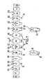
- the invention consists in that the measuring head consists of plate-shaped individual elements, preferably made of cardboard, with an approximately rectangular basic shape, which extends in a direction perpendicular to the plate plane, preferably from the two sides of a central plate-shaped element, placed on top of each other and attached to each other.
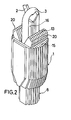
- the invention provides that the measuring head consists of a cylindrical base body and the central plate-shaped element has the greatest width, the width of the other elements placed to form the cylindrical body decreases, and at least one, preferably two of the plate-shaped individual elements at the lower end is provided with approaches to form the coupling for the electrical connection with the coupling piece of the lance.
- the measuring head can be produced very economically in a fully automated workflow, which is important because it is a mass article that is required in large quantities.
- the plate-shaped elements have an approximately rectangular basic shape.
- the middle plate M has the greatest width, while the width of the plates a to g or A to G adjoining on both sides decreases to form a cylindrical base body 1 (FIG. 2).
- the individual elements arranged on both sides of the central element M and at corresponding locations have practically the same shape, ie a corresponds to A, b corresponds to B, etc.
- the central plate-shaped element M is centered with a Y projecting upwards -shaped web 2 provided, which serves as a support for the quartz tube 3.
- the middle element M and the plate-shaped elements a and A lying thereon are provided at their lower ends with fork-like projections 4, by means of which a middle elongated recess 5 is formed.
- the two following elements B and b have a tongue-shaped extension 6 at the corresponding points, approximately the size of the fork-like extension, but without the central recess.
- the invention provides for the surface of the tongue-shaped extension 6 facing the cavity 7 to be provided with a coating of conductive material.
- the element B is provided with a coating 9 which is somewhat narrower than the tongue-shaped extension 6 and extends up to the upper section of the element.
- the coating which can be a copper foil, for example, ends in the vicinity of a central rectangular cutout 10, which is provided on this and possibly one or more subsequent elements and serves to receive a leg end of the quartz tube 3.
- the second electrical contact is formed on the plate b.
- the side of the tongue-shaped extension 6 of the individual element b facing away from the cavity is provided with a coating 11 made of conductive material, which is drawn over the side edges of the tongue-shaped extension and is also led up to the upper section of the element.
- a rectangular cutout 10 for receiving the other leg end of the quartz tube is also provided on this and possibly the following elements c, d, e.
- the rear sides provided with the coating of the individual shown in the upper part of FIG. 1 elements B and b lie on the elements shown below these above.
- the wires of the thermocouple which are known to be guided through the quartz tube, can be attached to the conductive layers 9 and 11 in a simple manner by clamping the wires with adjacent individual elements.
- the rectangular cutouts are provided on the plates B to E and b to e. It is possible to make the cutouts a little deeper in one group of individual elements than in the other group, e.g. if the quartz tube has 3 legs with different lengths. In the exemplary embodiment shown in FIG. 1, the cutouts 10 in elements b to e are somewhat deeper than in elements B to E.
- the upper edges 15 of the plate-shaped elements are provided symmetrically with respect to the center line with two projections 13 projecting upward from the side edges and serving to form contact surfaces 20 for the central cutout of a disk 14.
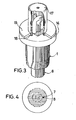
- This disc the thickness of which corresponds approximately to the height of the shoulders, is placed on the upper part of the body 1, as is evident, for example, from FIG. 3, and clamped to the contact surfaces of the shoulders 13. It lies on the exposed portions of the upper edges 15 of the plate-shaped elements, as well as on the upper edges of one or more, the furthest outside seated plate-shaped elements f, g or F, G, which are not provided with approaches.
- the approaches 13 form an approximately square contact surface 20, which can also be circular or similar.
- the individual plates a and A which bear directly against the central element M also have an upwardly projecting tongue-shaped projection 16 which reinforces the central section of the Y-shaped web 2.
- the legs of the quartz tube lie against the shoulders 16.
- the parts of the measuring head protruding from the upper side of the disk 14 are covered with a cap 17, which is made of metallic material.
- the cap is provided at its lower open end with an outwardly flanged edge 18 and is held in place with a mounting plate 19 having a central opening corresponding to the cross section of the cap, in that the edge portion of the opening of the plate 19 is on the flanged edge 18 of the cap rests.
- the plate 19 is attached to the surface of the disk 14, for example by gluing.
- the cavity surrounding the quartz tube can be filled with refractory cement.
- the production of the measuring heads according to the present invention can be carried out fully automatically in an extremely simple and economical manner. It is provided that the individual plate-shaped elements are produced by punching out a strip of suitable cardboard, which has a thickness of about 1 mm. The individual plate-shaped elements can be attached to each other by gluing them together. There is also the possibility of combining two or more of the plates arranged on both sides of the central element and of one piece from a correspondingly thicker one To produce material.
- the approximately rectangular part of the plates has a height of approximately 25 mm, for example; the height of the upper lugs 13 is about 5 mm, the length of the lower tongue-shaped lugs about 10 mm.
- the width of the central element can be approximately 15 to 20 mm, so that when using an appropriate number of plates, a cylindrical base body with a diameter of 15 to 20 mm is formed. Of course, larger or smaller measuring heads can also be manufactured.
Landscapes
- Physics & Mathematics (AREA)
- General Physics & Mathematics (AREA)
- Measuring Temperature Or Quantity Of Heat (AREA)
- Investigating Or Analyzing Materials Using Thermal Means (AREA)
Abstract
Description
- -1 Die Erfindung bezieht sich auf einen verbrauchbaren Meßkopf für die Durchführung thermischer und analytischer Bestimmungen, vorzugsweise zur Temperaturmessung in flüssigen Metallen, der auf das mit einem Kupplungsstück versehene Ende einer hohlen Lanze, insbesondere aus Pappe, aufsteckbar ist, durch die die elektrischen Ausgleichsleitungen zu einem Meßinstrument geführt sind, wobei der Meßkopf mit einer eine elektrische Verbindung zu einem Thermoelement schaffenden Kupplung versehen ist, die auf ein Kupplungsstück der Lanze paßt und die Heißlötstelle des Thermoelementes in einem U-förmigen Quarzrohr angeordnet ist, das an dem der Kupplung gegenüberliegenden Ende des Meßkopfes vorgesehen ist.
- Derartige verbrauchbare oder verlorene Temperaturfühler werden beispielsweise zur Messung der Temperatur von Stahlschmelzen verwendet. Sie bestehen im allgemeinen aus einem zylindrischen Grundkörper aus isolierendem Material, z.B. einem Körper aus keramischen Material oder aus Quarzsand, in den auf der einen Seite das U-förmige Quarzrohr mit den Drähten des Thermoelementes eingesetzt ist, während das andere Ende die meist als Steckverbindung ausgebildete, in das Kupplungsstück der Lanze passende Kupplung enthält. Die Steckverbindung besteht aus kontakttragenden Oberflächen aus weichelastischem Kunststoff. Derartige Tauchthermoelemente sind beispielsweise aus der DE-PS 1 648 203 und der DE-OS 2 549 140 bekannt. Bei diesen besteht das an der Meßlanze vorgesehene Kupplungsstück aus einem Kontaktstift, der koaxial zu einem Kontaktzylinder angeordnet ist. In dieses Kontaktstück passen die aus weichelastischem Werkstoff bestehenden Kontaktträger des Thermoelementes, die sowohl an dem Kontaktstift als auch an dem Kontaktzylinder anliegen.
- Die Herstellung der bekannten Meßköpfe aus keramischem oder einem ähnlichen Material, insbesondere der Zusammenbau der einzelnen Teile einschließlich der Verbindung der Kontaktoberflächen mit den Drähten des Thermoelementes erfordert einen nicht unerheblichen Aufwand. Eine vollautomatische Fertigung ist bisher nicht möglich gewesen; vielmehr müssen eine Reihe von Arbeitsgängen von Hand vorgenommen werden.
- Der Erfindung liegt die Aufgabe zugrunde, einen Meßkopf mit einer Steckverbindung zum Anschluß an das Kupplungsstück einer Lanze einfacher und so auszubilden, daß eine vollautomatische Fertigung möglich ist.
- Ausgehend von einem Meßkopf der eingangs beschriebenen Art besteht die Erfindung darin, daß der Meßkopf aus plattenförmigen, vorzugsweise aus Pappe gefertigen Einzelelementen mit etwa rechteckiger Grundform besteht, die in einer senkrecht zur Plattenebene verlaufenden Richtung, vorzugsweise von den beiden Seiten eines mittleren plattenförmigen Elementes aus, aufeinandergelegt und aneinander befestigt sind.
- Die Erfindung sieht vor, daß der Meßkopf aus einem zylinderförmig ausgebildeten Grundkörper besteht und das mittlere plattenförmige Element die größte Breite hat, wobei die Breite der weiteren aufgelegten Elemente zur Bildung des zylinderförmigen Körpers abnimmt, und mindestens eins, vorzugsweise zwei der plattenförmigen Einzelelemente am unteren Ende mit Ansätzen zur Bildung der Kupplung für die elektrische Verbindung mit dem Kupplungsstück der Lanze versehen ist.
- Weitere Merkmale ergeben sich aus den Unteransprüchen.
- Es hat sich überraschenderweise herausgestellt, daß es möglich ist, einen zylinderartigen Meßkopf mit den Anlageflächen zum Einstecken in eine Lanze, insbesondere in ein Papprohr sowie einer Kupplung zum Anschluß an das Kupplungsstück der Lanze aus einzelnen Platten aus Pappe zu fertigen, die bei der Herstellung des Meßkopfes, bei- i spielsweise durch Kleben, aufeinander befestigt werden. Dabei ist es gleichzeitig möglich, die aus den Schenkeln des U-förmigen Quarzrohres herausragenden Drähte des Thermoelementes in einfacher Weise zwischen zwei mit einer Schicht aus leitendem Material versehenen Platten zu verklemmen. Die einzelnen Platten können beispielsweise aus einem Pappstreifen entsprechender Stärke durch Ausstanzen gefertigt werden.
- Der Meßkopf läßt sich in sehr wirtschaftlicher Weise in einem vollautomatisierten Arbeitsablauf herstellen, was deswegen von Bedeutung ist, weil es sich um einen Massenartikel handelt, der in großer Stückzahl benötigt wird.
- Auf der Zeichnung ist ein Ausführungsbeispiel der Erfindung dargestellt. Es zeigen:
- Figur 1 eine Draufsicht auf die einzelnen plattenförmigen Einzelelemente, die zur Bildung des zylinderförmigen Grundkörpers aufeinandergeschichtet werden,
- Figur 2 eine perspektivische Darstellung des Grundkörpers,
- Figur 3 eine perspektivische Darstellung des fertigen Meßkopfes und
- Figur 4 eine Ansicht auf den in Figur 3 dargestellten Meßkopf von unten.
- Figur 1 zeigt die Form der einzelnen plattenförmigen Einzelelemente, die in der Reihenfolge nebeneinander dargestellt wurden, in der sie zur Bildung des auf Figur 2 dargestellten Grundkörpers zusammengefügt werden. Dabei bildet die auf der Zeichnung am weitesten rechts liegende Platte g die unterste und die Platte G die oberste Platte, wobei die auf der Zeichnung dargestellte Oberseite jeweils die nach oben gerichtete Fläche bleibt, d.h. f wird auf g, e auf f aufgelegt usw.
- Die plattenförmigen Elemente haben eine etwa rechteckige Grundform. Die mittlere Platte M hat die größte Breite, während die Breite der sich auf beiden Seiten anschließenden Platten a bis g bzw. A bis G zur Bildung eines zylinderartigen Grundkörpers 1 (Figur 2) abnimmt. Wie sich aus Figur 1 ergibt, haben die auf beiden Seiten des mittleren Elerentes M und an entsprechenden Stellen angeordneten Einzelelemente praktisch die gleiche Gestalt, d.h. a entspricht A, b entspricht B usw. Das mittlere plattenförmige Element M ist mittig mit einem nach oben vorstehenden Y-förmigen Steg 2 versehen, der als Auflage für das Quarzrohr 3 dient. Ferner sind das mittlere Element M und die daran anliegenden plattenförmigen Elemente a und A an ihrem unteren Ende mit gabelartigen Ansätzen 4 versehen, durch die eine mittlere längliche Ausnehmung 5 gebildet wird. Die beiden folgenden Elemente B und b haben an den entsprechenden Stellen einen zungenförmigen Ansatz 6, etwa von der Größe des gabelartigen Ansatzes, jedoch ohne die mittige Ausnehmung. Auf diese Weise wird beim Auflegen von je zwei Elementen (a, b und A, B) auf das mittlere Element am unteren Ende des so gebildeten Körpers ein Hohlraum mit einem rechteckigen bzw. quadratischen Querschnitt gebildet, der einen Teil der Kupplung zum Anschluß des Meßkopfes an die Lanze darstellt. Der Hohlraum ist auf Figur 4 sichtbar und mit dem Bezugszeichen ? versehen. Auch weitere, sich auf beiden Seiten anschließende Einzelelemente können an ihren unteren Enden mit zungenförmigen Ansätzen 6 versehen sein. Bei dem auf der Zeichnung dargestellten Ausführungsbeispiel haben die Elemente c und d sowie C und D derartige Ansätze mit einer abnehmenden Breite. Bei den weiteren, sich an die Einzelelemente D bzw. d anschließenden Platten e, f, g bzw. E, F, G fehlt der untere zungenförmige Ansatz. Auf diese Weise wird am unteren Ende des Körpers 1 ein Ansatz 8 mit einem etwa zylinderförmigen Außenumfang gebildet, in dessen Mitte sich der Hohlraum 7 befindet. Der Ansatz 8 bildet zusammen mit dem Hohlraum 7 die Kupplung für den Anschluß des Meßkopfes an das Kupplungsstück der Lanze. Zur Bildung einer elektrischen Kontaktstelle sieht die Erfindung vor, die dem Hohlraum 7 zugewandte Fläche des zungenförmigen Ansatzes 6 mit einer Beschichtung aus leitendem Material zu versehen. Bei dem auf Figur 1 dargestellten Ausführungsbeispiel ist das Element B mit einer Beschichtung 9 versehen, die etwas schmaler ist als der zungenförmige Ansatz 6 und bis zum oberen Abschnitt des Elementes hochgeführt ist. Die Beschichtung, bei der es sich beispielsweise um eine Kupferfolie handeln kann, endet in der Nähe eines mittleren rechteckigen Ausschnittes 10, der an diesem und gegebenenfalls einem oder mehreren folgenden Elementen vorgesehen ist und zur Aufnahme eines Schenkelendes des Quarzrohres 3 dient. Der zweite elektrische Kontakt wird an der Platte b gebildet. Zu diesem Zweck wird die dem Hohlraum abgewandte Seite des zungenförmigen Ansatzes 6 des Einzelelementes b mit einer Beschichtung 11 aus leitendem Material versehen, die über die Seitenkanten des zungenförmigen Ansatzes gezogen und ebenfalls bis zum oberen Abschnitt des Elementes hochgeführt ist. Auch an diesem und gegebenenfalls den folgenden Elementen c, d, e ist ein rechteckiger Ausschnitt 10 zur Aufnahme des anderen Schenkelendes des Quarzrohres vorgesehen. Die mit der Beschichtung versehenen Rückseiten der im oberen Teil der Figur 1 dargestellten Einzelelemente B und b liegen auf den unter diesen abgebildeten Elementen oben.
- Die Befestigung der Drähte des Thermoelementes, die bekanntlich durch das Quarzrohr geführt werden, mit den leitenden Schichten 9 und 11 kann in einfacher Weise durch Verklemmen der Drähte mit benachbarten Einzelelementen erfolgen. Zu diesem Zweck besteht die Möglichkeit, auf den Flächen der benachbarten Platten A bzw. c, die an den beschichteten Flächen anliegen, schmale quer verlaufende leitende Schichten 12 anzubringen, so daß die Drähte des Thermoelementes beim Zusammenfügen der Platten zwischen zwei leitenden Schichten verklemmt werden.
- Wie sich aus Figur 1 ergibt, sind die rechteckigen Ausschnitte an den Platten B bis E und b bis e vorgesehen. Es besteht die Möglichkeit, die Ausschnitte bei der einen Gruppe von Einzelelementen etwas tiefer als bei der anderen Gruppe zu gestalten, z.B. wenn das Quarzrohr 3 Schenkel mit unterschiedlichen Längen hat. Bei dem auf Figur 1 dargestellten Ausführungsbeispiel sind die Ausschnitte 10 bei den Elementen b bis e etwas tiefer als bei den Elementen B bis E.
- Die oberen Kanten 15 der plattenförmigen Elemente sind symmetrisch zur Mittellinie mit zwei gegenüber den Seitenkanten zurückspringenden, nach oben vorstehenden Ansätzen 13 versehen, die zur Bildung von Anlageflächen 20 für den mittleren Ausschnitt einer Scheibe 14 dienen. Diese Scheibe, deren Stärke etwa der Höhe der Ansätze entspricht, wird, wie sich beispielsweise aus Figur 3 ergibt, auf den oberen Teil des Körpers 1 aufgesetzt und an den Anlageflächen der Ansätze 13 verklemmt. Dabei liegt sie auf den freigebliebenen Abschnitten der oberen Kanten 15 der plattenförmigen Elemente, sowie auf den oberen Kanten eines oder mehrerer, am weitesten außen sitzender plattenförmiger Elemente f, g bzw. F, G, die nicht mit Ansätzen versehen sind, auf.
- Bei dem dargestellten Ausführungsbeispiel wird durch die Ansätze 13 eine in etwa quadratische Anlagefläche 20 gebildet, die auch kreisförmig oder ähnlich sein kann. Die unmittelbar an dem mittleren Element M anliegenden Einzelplatten a und A haben darüber hinaus noch einen nach oben vorstehenden zungenförmigen Ansatz 16, der den mittleren Abschnitt des Y-förmigen Steges 2 verstärkt. An den Ansätzen 16 liegen die Schenkel des Quarzrohres an.
- Die gegenüber der Oberseite der Scheibe 14 vorstehenden Teile des Meßkopfes sind mit einer Kappe 17, die aus metallischem Werkstoff besteht, abgedeckt. Die Kappe ist an ihrem unteren offenen Ende mit einem nach außen umgebördelten Rand 18 versehen und wird mit einer Befestigungsplatte 19, die eine mittlere, dem Querschnitt der Kappe entsprechende Öffnung hat, dadurch festgehalten, daß der Randabschnitt der Öffnung der Platte 19 auf dem umgebördelten Rand 18 der Kappe aufliegt. Die Platte 19 wird beispielsweise durch Kleben auf der Oberfläche der Scheibe 14 befestigt. Der das Quarzrohr umgebende Hohlraum kann mit feuerfestem Zement ausgefüllt werden.
- Die Herstellung der Meßköpfe gemäß vorliegender Erfindung kann in einer äußerst einfachen und wirtschaftlichen Weise vollautomatisch durchgeführt werden. Dabei ist vorgesehen, daß die einzelnen plattenförmigen Elemente durch Ausstanzen aus einem Streifen aus geeigneter Pappe hergestellt werden, die eine Stärke von etwa 1 mm hat. Die einzelnen plattenförmigen Elemente können durch Zusammenkleben aneinander befestigt werden. Es besteht auch die Möglichkeit, zwei oder mehr der auf beiden Seiten des mittleren Elementes angeordneten Platten zusammenzufassen und aus einem Stück aus einem entsprechend stärkeren Material herzustellen.
- Der etwa rechteckige Teil der Platten hat beispielsweise eine Höhe von etwa 25 mm; die Höhe der oberen Ansätze 13 beträgt etwa 5 mm, die Länge der unteren zungenförmigen Ansätze etwa 10 mm. Die Breite des mittleren Elementes kann etwa 15 bis 20 mm betragen, so daß bei Verwendung einer entsprechenden Anzahl von Platten ein zylindrischer Grundkörper mit einem Durchmesser von 15 bis 20 mm gebildet wird. Selbstverständlich können auch größere oder kleinere Meßköpfe hergestellt werden.
Claims (20)
Applications Claiming Priority (2)
| Application Number | Priority Date | Filing Date | Title |
|---|---|---|---|
| DE3000174 | 1980-01-04 | ||
| DE3000174A DE3000174C2 (de) | 1980-01-04 | 1980-01-04 | Verbrauchbarer Meßkopf für Tauchthermoelemente |
Publications (3)
| Publication Number | Publication Date |
|---|---|
| EP0033005A2 true EP0033005A2 (de) | 1981-08-05 |
| EP0033005A3 EP0033005A3 (en) | 1982-02-24 |
| EP0033005B1 EP0033005B1 (de) | 1984-05-30 |
Family
ID=6091535
Family Applications (1)
| Application Number | Title | Priority Date | Filing Date |
|---|---|---|---|
| EP80108003A Expired EP0033005B1 (de) | 1980-01-04 | 1980-12-18 | Verbrauchbarer Messkopf für Tauchthermoelemente |
Country Status (6)
| Country | Link |
|---|---|
| US (1) | US4363929A (de) |
| EP (1) | EP0033005B1 (de) |
| JP (1) | JPS56111436A (de) |
| CA (1) | CA1148380A (de) |
| DE (1) | DE3000174C2 (de) |
| ZA (1) | ZA807404B (de) |
Families Citing this family (2)
| Publication number | Priority date | Publication date | Assignee | Title |
|---|---|---|---|---|
| US4603980A (en) * | 1984-02-03 | 1986-08-05 | Owens-Corning Fiberglas Corporation | Methods of measuring temperature and electrical resistivity in a molten glass stream |
| US6160215A (en) | 1999-03-26 | 2000-12-12 | Curtin; Lawrence F. | Method of making photovoltaic device |
Family Cites Families (14)
| Publication number | Priority date | Publication date | Assignee | Title |
|---|---|---|---|---|
| US2390721A (en) * | 1942-05-25 | 1945-12-11 | Mallgraf Ferdinand | Nonmetallic ferrule for caps of containers |
| US2998840A (en) * | 1957-02-28 | 1961-09-05 | Polymer Corp | Laminated strip product for electrical purposes |
| US3055691A (en) * | 1959-11-05 | 1962-09-25 | Kessel John | Circular faceplate for door latches |
| GB956324A (en) * | 1961-04-17 | 1964-04-22 | Harco Chemical Inc | Heat resistant objects such as composite tubes |
| GB942617A (en) * | 1961-09-23 | 1963-11-27 | Land Pyrometers Ltd | Improvements in or relating to thermocouple pyrometers |
| GB987877A (en) * | 1961-11-01 | 1965-03-31 | Dufaylite Dev Ltd | Improvements in or relating to honeycomb materials |
| US3306783A (en) * | 1961-12-20 | 1967-02-28 | Electro Nite Engineering Co | Disposable thermocouple lance |
| US3427208A (en) * | 1965-07-26 | 1969-02-11 | Electro Nite | Expendable thermocouple with locater means |
| US3559452A (en) * | 1967-09-25 | 1971-02-02 | Republic Steel Corp | Thermal analysis of molten steel |
| US3698954A (en) * | 1968-12-09 | 1972-10-17 | Leeds & Northrup Co | Expendable immersion thermocouple assembly |
| US3725134A (en) * | 1970-04-23 | 1973-04-03 | Massillon Measurement Inc | Expendable immersion thermocouple unit |
| DE2549140A1 (de) * | 1975-11-03 | 1977-05-05 | Gustav Kolb Fabrik Elektrokera | Steckverbindung fuer ein tauchthermoelement |
| US4294643A (en) * | 1978-09-05 | 1981-10-13 | Uop Inc. | Heater assembly and method of forming same |
| FR2462694A3 (fr) * | 1979-07-31 | 1981-02-13 | Tersid Srl | Thermocouple a immersion |
-
1980
- 1980-01-04 DE DE3000174A patent/DE3000174C2/de not_active Expired
- 1980-11-27 ZA ZA00807404A patent/ZA807404B/xx unknown
- 1980-12-18 EP EP80108003A patent/EP0033005B1/de not_active Expired
- 1980-12-23 US US06/219,471 patent/US4363929A/en not_active Expired - Fee Related
- 1980-12-23 JP JP18141280A patent/JPS56111436A/ja active Granted
- 1980-12-29 CA CA000367603A patent/CA1148380A/en not_active Expired
Also Published As
| Publication number | Publication date |
|---|---|
| DE3000174C2 (de) | 1982-05-19 |
| EP0033005A3 (en) | 1982-02-24 |
| EP0033005B1 (de) | 1984-05-30 |
| US4363929A (en) | 1982-12-14 |
| JPS618372B2 (de) | 1986-03-13 |
| DE3000174A1 (de) | 1981-07-09 |
| JPS56111436A (en) | 1981-09-03 |
| CA1148380A (en) | 1983-06-21 |
| ZA807404B (en) | 1981-11-25 |
Similar Documents
| Publication | Publication Date | Title |
|---|---|---|
| DE1514827C2 (de) | Verfahren zur serienmäßigen Herstellung von Halbleiterbauelementen | |
| DE3686693T2 (de) | Ausrichtungsvorrichtung eines halbleiterplaettchentraegers und verfahren zum ausrichten. | |
| EP3929594B1 (de) | Verfahren zur herstellung einer vorrichtung zur messung von stromstärken und vorrichtung zur messung von stromstärken | |
| DE3808971A1 (de) | Zusammengesetztes bauelement | |
| DE69226968T2 (de) | Lottragender anschlussdraht | |
| CH686325A5 (de) | Elektronikmodul und Chip-Karte. | |
| DE4212883C2 (de) | Temperaturfühler | |
| DE2334427A1 (de) | Baugruppe fuer ein lsi-plaettchen und herstellungsverfahren | |
| DE19822511B4 (de) | Auf einer Oberfläche befestigbare elektronische Bauelemente | |
| DE1614975C3 (de) | Montageband zum Anschließen von elektrischen Bauelementen und Verfahren zum Herstellen eines solchen Montagebandes | |
| DE2213823B2 (de) | Verfahren und Vorrichtung zum Montieren von elektrischen Bauelementen auf einer Leiterplatte | |
| DE2159530A1 (de) | Verfahren zum Herstellen einer Halbleiteranordnung, Halbleiteranordnung und metallenes Leitergitter zur Anwendung bei der Herstellung einer Halbleiteranordnung | |
| DE2618994B2 (de) | Verfahren zur Herstellung von von Kontaktblechstücken durchragten Unterteilen bzw. Sockeln für elektromagnetische Relais | |
| DE3000174C2 (de) | Verbrauchbarer Meßkopf für Tauchthermoelemente | |
| DE2735143A1 (de) | Vierseitiger elektrischer bauteil und verfahren zur herstellung | |
| DE3229020A1 (de) | Einrichtung zur anzeige einer uebertemperatur eines elektrischen leiters | |
| DE2752847C3 (de) | Gehäuse mit einem darin angeordneten elektrischen Bauelement | |
| DE19851532C2 (de) | Sicherungshalter | |
| DE112018000648T5 (de) | Verbinder und verfahren zum herstellen einer elektrischen verbindungsanordnung, welche mit demselben versehen ist | |
| DE69104881T2 (de) | Flacher Leistungswiderstand. | |
| DE2123068A1 (de) | Sicherungsaufbau | |
| DE10232821B4 (de) | Verfahren zum Herstellen von Sensoren zum elektrischen Messen der Füllstandshöhe sowie Einrichtung zum Herstellen solcher Sensoren | |
| DE20008664U1 (de) | Temperaturfühler | |
| DE3816538C2 (de) | ||
| DE1439717C3 (de) | Verfahren zur Herstellung eines Halbleiterbauelementes |
Legal Events
| Date | Code | Title | Description |
|---|---|---|---|
| PUAI | Public reference made under article 153(3) epc to a published international application that has entered the european phase |
Free format text: ORIGINAL CODE: 0009012 |
|
| AK | Designated contracting states |
Designated state(s): BE CH FR GB IT LI LU NL SE |
|
| PUAL | Search report despatched |
Free format text: ORIGINAL CODE: 0009013 |
|
| AK | Designated contracting states |
Designated state(s): BE CH FR GB IT LI LU NL SE |
|
| 17P | Request for examination filed |
Effective date: 19820405 |
|
| ITF | It: translation for a ep patent filed | ||
| RBV | Designated contracting states (corrected) |
Designated state(s): BE CH FR GB IT LI LU NL SE |
|
| GRAA | (expected) grant |
Free format text: ORIGINAL CODE: 0009210 |
|
| AK | Designated contracting states |
Designated state(s): BE CH FR GB IT LI LU NL SE |
|
| ET | Fr: translation filed | ||
| PGFP | Annual fee paid to national office [announced via postgrant information from national office to epo] |
Ref country code: FR Payment date: 19841019 Year of fee payment: 5 |
|
| PGFP | Annual fee paid to national office [announced via postgrant information from national office to epo] |
Ref country code: CH Payment date: 19841129 Year of fee payment: 5 |
|
| PG25 | Lapsed in a contracting state [announced via postgrant information from national office to epo] |
Ref country code: LU Free format text: LAPSE BECAUSE OF NON-PAYMENT OF DUE FEES Effective date: 19841231 |
|
| PGFP | Annual fee paid to national office [announced via postgrant information from national office to epo] |
Ref country code: SE Payment date: 19841231 Year of fee payment: 5 Ref country code: BE Payment date: 19841231 Year of fee payment: 5 |
|
| PLBE | No opposition filed within time limit |
Free format text: ORIGINAL CODE: 0009261 |
|
| STAA | Information on the status of an ep patent application or granted ep patent |
Free format text: STATUS: NO OPPOSITION FILED WITHIN TIME LIMIT |
|
| 26N | No opposition filed | ||
| PGFP | Annual fee paid to national office [announced via postgrant information from national office to epo] |
Ref country code: NL Payment date: 19851231 Year of fee payment: 6 |
|
| PG25 | Lapsed in a contracting state [announced via postgrant information from national office to epo] |
Ref country code: SE Effective date: 19861219 |
|
| PG25 | Lapsed in a contracting state [announced via postgrant information from national office to epo] |
Ref country code: LI Effective date: 19861231 Ref country code: CH Effective date: 19861231 |
|
| PG25 | Lapsed in a contracting state [announced via postgrant information from national office to epo] |
Ref country code: NL Effective date: 19870701 |
|
| NLV4 | Nl: lapsed or anulled due to non-payment of the annual fee | ||
| GBPC | Gb: european patent ceased through non-payment of renewal fee | ||
| PG25 | Lapsed in a contracting state [announced via postgrant information from national office to epo] |
Ref country code: FR Free format text: LAPSE BECAUSE OF NON-PAYMENT OF DUE FEES Effective date: 19870831 |
|
| REG | Reference to a national code |
Ref country code: CH Ref legal event code: PL |
|
| REG | Reference to a national code |
Ref country code: FR Ref legal event code: ST |
|
| PG25 | Lapsed in a contracting state [announced via postgrant information from national office to epo] |
Ref country code: GB Free format text: LAPSE BECAUSE OF NON-PAYMENT OF DUE FEES Effective date: 19881118 |
|
| PG25 | Lapsed in a contracting state [announced via postgrant information from national office to epo] |
Ref country code: BE Effective date: 19891231 |
|
| BERE | Be: lapsed |
Owner name: ELECTRO-NITE N.V. Effective date: 19891231 |
|
| EUG | Se: european patent has lapsed |
Ref document number: 80108003.7 Effective date: 19870902 |