EP0032402A2 - Gerüstsystem - Google Patents
Gerüstsystem Download PDFInfo
- Publication number
- EP0032402A2 EP0032402A2 EP81100195A EP81100195A EP0032402A2 EP 0032402 A2 EP0032402 A2 EP 0032402A2 EP 81100195 A EP81100195 A EP 81100195A EP 81100195 A EP81100195 A EP 81100195A EP 0032402 A2 EP0032402 A2 EP 0032402A2
- Authority
- EP
- European Patent Office
- Prior art keywords
- lever
- scaffolding system
- housing
- protrusion
- locking position
- Prior art date
- Legal status (The legal status is an assumption and is not a legal conclusion. Google has not performed a legal analysis and makes no representation as to the accuracy of the status listed.)
- Granted
Links
- 230000015572 biosynthetic process Effects 0.000 claims description 18
- 230000005484 gravity Effects 0.000 claims description 4
- 230000002093 peripheral effect Effects 0.000 claims description 2
- 229910000831 Steel Inorganic materials 0.000 description 1
- XAGFODPZIPBFFR-UHFFFAOYSA-N aluminium Chemical compound [Al] XAGFODPZIPBFFR-UHFFFAOYSA-N 0.000 description 1
- 229910052782 aluminium Inorganic materials 0.000 description 1
- 239000004411 aluminium Substances 0.000 description 1
- 230000000712 assembly Effects 0.000 description 1
- 238000000429 assembly Methods 0.000 description 1
- 230000006835 compression Effects 0.000 description 1
- 238000007906 compression Methods 0.000 description 1
- 230000000694 effects Effects 0.000 description 1
- 239000010959 steel Substances 0.000 description 1
Images
Classifications
-
- E—FIXED CONSTRUCTIONS
- E04—BUILDING
- E04G—SCAFFOLDING; FORMS; SHUTTERING; BUILDING IMPLEMENTS OR AIDS, OR THEIR USE; HANDLING BUILDING MATERIALS ON THE SITE; REPAIRING, BREAKING-UP OR OTHER WORK ON EXISTING BUILDINGS
- E04G7/00—Connections between parts of the scaffold
- E04G7/30—Scaffolding bars or members with non-detachably fixed coupling elements
- E04G7/302—Scaffolding bars or members with non-detachably fixed coupling elements for connecting crossing or intersecting bars or members
- E04G7/306—Scaffolding bars or members with non-detachably fixed coupling elements for connecting crossing or intersecting bars or members the added coupling elements are fixed at several bars or members to connect
- E04G7/308—Scaffolding bars or members with non-detachably fixed coupling elements for connecting crossing or intersecting bars or members the added coupling elements are fixed at several bars or members to connect without tying means for connecting the bars or members
-
- Y—GENERAL TAGGING OF NEW TECHNOLOGICAL DEVELOPMENTS; GENERAL TAGGING OF CROSS-SECTIONAL TECHNOLOGIES SPANNING OVER SEVERAL SECTIONS OF THE IPC; TECHNICAL SUBJECTS COVERED BY FORMER USPC CROSS-REFERENCE ART COLLECTIONS [XRACs] AND DIGESTS
- Y10—TECHNICAL SUBJECTS COVERED BY FORMER USPC
- Y10T—TECHNICAL SUBJECTS COVERED BY FORMER US CLASSIFICATION
- Y10T403/00—Joints and connections
- Y10T403/30—Laterally related members connected by latch means, e.g., scaffold connectors
Definitions
- THE PRESENT INVENTION relates to scaffolding. More particularly the present invention relates to a scaffolding system including a joint between two substantially perpendicular scaffold members, one of said members having a protruding formation thereon, the other having a pivotally mounted lever with a cam face that can be brought into contact with part of said protruding formation to lock the said two members together.
- the disclosed scaffolding includes a vertical member which is provided with four protruding lugs thereon, the lugs being radially equi-spaced about the periphery of the vertical member. Each lug defines a vertical central rectangular aperture therethrough. Horizontal members which are to be connected to this vertical member are each provided with a hook-shaped assembly at the free end thereof, a part of each hook shaped assembly being adapted to be inserted through a respective lug. This portion that is adapted to be inserted through the luf carries the said pivotally mounted lever, and the lever can be moved to engage the undersurface of the lug to lock the horizontal member into position.
- This prior proposed scaffolding system suffers from disadvantages.
- One particular disadvantage is that the horizontal members can only be connected to the vertical member whilst extending in one of four predetermined directions.
- a further disadvantage of the prior system is that,-since the pivotal lever is carried by a part of a hook shaped assembly that must pass through a lug, the lever must be relatively small, or alternatively, the lug must be relatively large.
- the present invention seeks to provide a scaffolding system including a joint which reduces or obviates the disadvantages of the above described prior proposed system.
- a scaffolding system including a joint between two substantially perpendicuilar scaffold members, one of said members having a protruding formation thereon, the other having a pivotally mounted lever with a cam face that can be brought into contact with part of said protruding formation to lock the said two members together, wherein said protruding formation comprises an annular formation, which is substantially uniform around the periphery of said one member,said lever being carried by a housing mounted on one end of the second member adapted to cooperate with said protruding formation so that said second member may have any desired radial orientation relative to the first said member.
- the first member on which the protruding formation is formed is upright and said protruding formation may comprise an annular member in the form of a dish or cup having an upwardly directed peripheral lip.
- said second member is provided with a housing at the free end thereof, said housing having a downwardly extending portion defined by a recess formed in the housing adapted to be engaged with said protruding formation.
- Said second member may be provided with means which at least partially embrace said first member to prevent twisting or rotation of the second member about an axis transverse to the first member.
- the second member may be engaged with and disengaged from the protrusion on the first member by moving the said one end of the second member in direction substantially parallel with the axis of the first member.
- said lever is biassed into a locking position, either by means of gravity or by means of a spring.
- the lever is initially moved away from the locking position against the said bias by means of engagement of the upwardly extending lip of the protrusion with part of the lever, the lever subsequently moving to the locking position with the cam on the locking lever .engaging the undersurface of the protrusion.
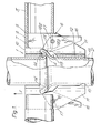
- the part of the scaffold in accordance with the invention which is illustrated constitutes a rigid connection 1 between a vertical tube or standard 2 and a horizontal tube or ledger 3.
- the standard and ledger may be formed of any appropriate tubing such as steel tubing or aluminium tubing.
- a dish or cup shaped protrusion 4 is formed, by a suitable compression and forming operation, integrally with the vertical tube 2.
- the protrusion 4 protruding radially and upwardly from the vertical tube 2.
- the protrusion is uniform around the entire periphery of the vertical tube 2.
- the clamping assembly 6 Connected to one end 5 of the horizontal tube 3 is a clamping assembly 6 which is utilised to clamp the horizontal member 3 to the protrusion 4.
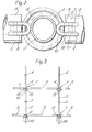
- the clamping assembly 6 comprises a housing 7 which is, when viewed in plan, of substantially "U” configuration, as can be seen from Figure 2.
- the two arms 8, 9 of the "U” configured housing are located in two parallel vertical slots cut into the end of the horizontal tube 3 and the housing 7 is welded in position.
- the upper surface 10 of the housing 7 is substantially flush with the upper surface of the horizontal tube 3, but a portion 11 of the housing 7 projects below the lower surface of the horizontal tube 3.
- the forwardly projecting part 12 of the housing 7 comprises the base of the "U" and is intended to abut against the side of the vertical tube 2.
- a recess 13 is cut in this forwardly projecting part 12 of the housing so that a downwardly extending portion 14 is defined which can engage over the lip defined by the protrusion 4.
- the housing 7 can be hooked over the protrusion 4 with the forwardly projecting part 12 of the housing 7 engaging the surface of the vertical tube 2.
- a clamping lever 16 is pivotally mounted about a pivot shaft 17, the pivot shaft 17 extending between the two arms 8, 9 of the housing 7. A portion of the clamping lever protrudes beyond the housing 7 so that the clamping lever can easily be grasped manually to rotate the clamping lever.
- the clamping lever 16 has a curved cam surface 18.
- the cam surface 18 is of such a configuration that the distance from an upper part 18a of the cam surface, as illustrated in Figure 1, to the pivot 17 is greater than the distance between a lower part 18b of the cam surface as illustrated in Figure 1 and the pivot 17.
- the cam surface 18 is so located that, when the housing 7 has been hooked over the protrusion 4, with the lever 16 in an initial position in which the protruding end of the lever is in close proximity with the vertical tube 2, the lower portion of the cam surface lies immediately adjacent the under surface of the protursion.
- the protruding end of the lever 16 may then be moved away from the tube 2, and the cam surface 18 will be brought into very firm wedging engagement with the undersurface of the protrusion 4.
- the horizontal tube 3 is rigidly secured to the protrusion 4.
- Appropriate tools may be used to rotate the lever if necessary.
- the lever 16 shall be biassed towards the locking position, and this can be achieved by providing the lever with an appropriate mass distribution relative to the pivot axis so that the lever will tend to rotate towards the locking position under the influence of gravity.
- scaffolding utilising connections as described above can be assembled to comprise a regular array of vertical tubes 2 and horizontal tubes 3. Also, as can be seen from Figure 3, protrusions 4 are provided at evenly spaced intervals on the vertical tubes 2.
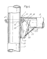
- Figure 4 it will be appreciated that the embodiment illustrated in Figure 4 is generally similar to the embodiment illstrated in Figures 1 to 3. Like reference numerals apply to like parts.
- the vertical tube is provided with a protrusion 4' in the form of a dish shaped annular element which is a separate element welded onto the vertical tube 2.
- the housing of the clamping assembly 7 is welded directly to the end of the horizontal tube 3 by means of a weld 19, the weld lying on a line at 45 degrees to the horizontal.
- the housing projects beyond the end of the horizontal tube 2, the upper surface 10 of the housing being flush with the upper surface of the tube, with a lower portion 11 of the housing projecting beneath the tube.
- a recess 13 is formed in the housing so that a downwardly extending portion 14 of the housing is defined that can be hooked over the protrusion 4 t .
- a tension spring 20 is shown in Figure 4 which serves to bias the lever 16 towards the locking position, the tension spring being connected to the lower end of the lever 16 and to the horizontal tube 3.
- scaffolding incorporating joints as described above may be easily and rapidily assembled.
- the upright tubes are temporarily held in position with the protrusions 4 or 4' directed upwardly, and the housings 7 of the clamping assemblies 6 are then manipulated so that the downwardly extending portions 14 are hooked over the lips of the protrusions 4.
- the uppermost lip of the securing formation will engage the pivoted lever 16, which is biassed towards the locking position by gravity or by the spring, and will move the lever 16 against this bias to enable the downwardly extending portion 14 of the housing to be located over the lip of the cup shaped projection.
- the lever 16 will then return to the locking position under its natural bias. This minimises the risk of any joint becoming loose, even if the levers are not manually forced into the locking position when the scaffolding is assembled.
- the described scaffolding joints may readily be disengaged by simply manually moving the locking lever 16 to a release position and lifting the housing 7 so that the downwardly extending portion 14 of the housing is disengaged from the protrusion 4 or 4'.
- scaffolding as described above has the advantage that the horizontal tubes can be located at any specific radial orientation relative to the vertical tube 1, since the protrusion 4 is an annular member which is uniform around the entire periphery of the vertical tube and thus does not pre-dictate any specific radial orientation for the horizontal tube 3.
- the locking lever 16 can be made to be of any convenient size, since the lever 16 does not have to pass through any apertures.It is envisaged that in certain embodiments of the invention, a pivotal mounting may be provided between the housing 7 and the tube 3, and thus the tube 3 may be moved to be inclined at any predetermined angle.
- embodiments of the invention may be prepared in which the housing is at a predetermined angle to the tube to which it is connected, so that the tube 3 will then extend at a predetermined angle relative to the vertical tube.
- a plurality of transverse members may be independentaly attached to or separated from a vertical tube at any given point. This enables complex scaffolding configurations to be achieved easily.
Landscapes
- Engineering & Computer Science (AREA)
- Architecture (AREA)
- Mechanical Engineering (AREA)
- Civil Engineering (AREA)
- Structural Engineering (AREA)
- Mutual Connection Of Rods And Tubes (AREA)
Priority Applications (1)
| Application Number | Priority Date | Filing Date | Title |
|---|---|---|---|
| AT81100195T ATE6801T1 (de) | 1980-01-15 | 1981-01-13 | Geruestsystem. |
Applications Claiming Priority (2)
| Application Number | Priority Date | Filing Date | Title |
|---|---|---|---|
| ZA800225 | 1980-01-15 | ||
| ZA80225 | 1980-01-15 |
Publications (3)
| Publication Number | Publication Date |
|---|---|
| EP0032402A2 true EP0032402A2 (de) | 1981-07-22 |
| EP0032402A3 EP0032402A3 (en) | 1982-02-17 |
| EP0032402B1 EP0032402B1 (de) | 1984-03-21 |
Family
ID=25574490
Family Applications (1)
| Application Number | Title | Priority Date | Filing Date |
|---|---|---|---|
| EP81100195A Expired EP0032402B1 (de) | 1980-01-15 | 1981-01-13 | Gerüstsystem |
Country Status (9)
| Country | Link |
|---|---|
| US (1) | US4369859A (de) |
| EP (1) | EP0032402B1 (de) |
| JP (1) | JPS56105062A (de) |
| AR (1) | AR225792A1 (de) |
| AT (1) | ATE6801T1 (de) |
| BR (1) | BR8100195A (de) |
| DE (1) | DE3162713D1 (de) |
| ES (1) | ES255573Y (de) |
| MX (1) | MX151347A (de) |
Cited By (6)
| Publication number | Priority date | Publication date | Assignee | Title |
|---|---|---|---|---|
| FR2478712A1 (fr) * | 1980-03-20 | 1981-09-25 | Bera Berliner Rahmengeruest | Echafaudage en tubes d'acier |
| EP0183864A1 (de) * | 1984-12-04 | 1986-06-11 | Röder, Edwin | Verbindung von mindestens zwei Dachbindern mit mehreren, Im wesentlichen horizontal verlaufenden, and den Dachbindern eingehängten, aushubsicherbaren Pfetten |
| EP0217779A3 (en) * | 1985-09-30 | 1988-03-23 | Yvon Plasman | Connecting device for scaffoldings |
| FR2682708A1 (fr) * | 1991-10-16 | 1993-04-23 | Nagel Gilbert | Dispositif de verrouillage de barres pour l'assemblage et le blocage de garde-corps. |
| EP0605411A4 (de) * | 1990-09-13 | 1993-08-20 | Joe W Williams | Verbesserte gerüstverbindung. |
| DE4438494A1 (de) * | 1994-10-28 | 1996-05-02 | Erich Albert | Knotenpunktgerüst mit Standrohren |
Families Citing this family (26)
| Publication number | Priority date | Publication date | Assignee | Title |
|---|---|---|---|---|
| CA1178076A (en) * | 1982-02-25 | 1984-11-20 | Anthes Equipment Limited | Shoring system |
| DE3236648A1 (de) * | 1982-10-04 | 1984-04-05 | Plettac Gmbh Stahlbau Und Gesenkschmiede, 5970 Plettenberg | Geruest, insbesondere baugeruest |
| US4445307A (en) * | 1982-11-08 | 1984-05-01 | Figgie International Inc. | Scaffold joint for a scaffold structure |
| US4549634A (en) * | 1983-04-15 | 1985-10-29 | Waco International Corporation | Scaffold connector assembly |
| US4586842A (en) * | 1985-08-23 | 1986-05-06 | Figgie International, Inc. | Scaffold joint for a scaffold structure |
| US4840513A (en) * | 1986-11-05 | 1989-06-20 | Hackett Steven B | Scaffolding connector apparatus |
| US5078532A (en) * | 1990-09-13 | 1992-01-07 | Williams Joe W | Scaffold connection |
| NL9100139A (nl) * | 1991-01-28 | 1992-08-17 | Leeuw Petrus J L De | Afsteunelement voor toepassing in bouwconstructies. |
| CA2111724A1 (en) * | 1993-12-17 | 1995-06-18 | Raymond Wayne Gillard | Scaffold system |
| GB9403141D0 (en) * | 1994-02-18 | 1994-04-06 | Jarvis Barry M F | A device for connecting a first elongate member to a transverse second elongate member |
| DE9409418U1 (de) * | 1994-06-10 | 1995-01-19 | Krause-Werk GmbH & Co KG, 36304 Alsfeld | Klemmverbindung zum Zusammenbau von vorgefertigten Profilstäben zu einem Baugerüst |
| US5762441A (en) * | 1996-05-17 | 1998-06-09 | Safway Steel Products, Inc. | End cap system for scaffolding planks |
| US5913340A (en) * | 1997-09-15 | 1999-06-22 | Composite Structures, Inc. | Walkway platform |
| US6729075B2 (en) * | 2000-10-19 | 2004-05-04 | Wenger Corporation | Audience seating system |
| JP4625352B2 (ja) * | 2005-03-25 | 2011-02-02 | 大和ハウス工業株式会社 | 支持係留金物 |
| US7971686B1 (en) | 2007-04-20 | 2011-07-05 | Excel Modular Scaffold And Leasing Corporation | Double latched scaffold connector |
| US8393439B2 (en) * | 2010-01-26 | 2013-03-12 | Steve Howard Thacker | Scaffold system and method |
| USD656814S1 (en) | 2010-11-01 | 2012-04-03 | Bauer Ryan E | Hinged cuplock scaffolding coupler |
| US20120186911A1 (en) * | 2011-01-25 | 2012-07-26 | Next Generation Scaffold Services Inc. | Scaffold apparatus, method and system |
| US9303417B2 (en) | 2011-01-25 | 2016-04-05 | Next Generation Scaffold Services, Inc. | Dual latching horizontal scaffold member |
| EP2649257B1 (de) | 2011-11-02 | 2017-08-09 | Saferite Platforms Inc. | Schwenkbares horizontales und vertikales gerüstelement und verfahren zur errichtung einer versetzten arbeitsbühne |
| US9260873B1 (en) | 2013-03-22 | 2016-02-16 | Deltak Manufacturing, Inc. | Truss member and truss connector |
| ES2587453B1 (es) * | 2015-03-17 | 2017-08-01 | Ayudame A Ayudarte S.L | Andamio modular desmontable articulado |
| RU2592878C1 (ru) * | 2015-07-21 | 2016-07-27 | Сергей Филиппович Луценко | Корпус клинового крепежного узла |
| US20190330862A1 (en) * | 2017-01-25 | 2019-10-31 | Bechtel Oil, Gas And Chemicals, Inc. | Scaffolding system for use with curvilinear walls and method of use |
| US11268288B2 (en) * | 2018-04-10 | 2022-03-08 | Deltak Manufacturing, Inc. | Triple latching horizontal scaffold member with three triggers |
Family Cites Families (11)
| Publication number | Priority date | Publication date | Assignee | Title |
|---|---|---|---|---|
| NL47908C (de) * | ||||
| US2308832A (en) * | 1941-04-01 | 1943-01-19 | John F Roney | Scaffold |
| US2845307A (en) * | 1954-04-19 | 1958-07-29 | Superior Scaffold Company | Detachable coupling for scaffold elements |
| GB901351A (en) * | 1957-11-16 | 1962-07-18 | John Burton | Improvements in or relating to scaffolding systems for use in building construction and the like |
| DE1559069A1 (de) * | 1965-06-10 | 1969-09-11 | Karl Sikler & Sohn | Geruestkupplung |
| FR2217972A5 (de) * | 1973-02-13 | 1974-09-06 | Haki Produkter Ab | |
| NL175840B (nl) * | 1973-10-10 | 1984-08-01 | Sgb Group Plc | Verbindingsconstructie voor toepassing in een buisvormige steiger of stelling. |
| DE2617271A1 (de) * | 1975-04-26 | 1976-11-04 | Frederick George Sharp | Geruest |
| NL7801928A (nl) * | 1978-02-21 | 1979-08-23 | Hanny Vierkant | Koppeling tussen een staander en een dwarsdeel, meer in het bijzonder van een steiger. |
| DE2842831C2 (de) * | 1978-10-02 | 1980-08-14 | Gerhard 5090 Leverkusen Dobersch | Stahlrohrgerüst |
| US4273463A (en) * | 1979-10-03 | 1981-06-16 | Gerhard Dobersch | Steel tube scaffold |
-
1981
- 1981-01-13 EP EP81100195A patent/EP0032402B1/de not_active Expired
- 1981-01-13 DE DE8181100195T patent/DE3162713D1/de not_active Expired
- 1981-01-13 AT AT81100195T patent/ATE6801T1/de not_active IP Right Cessation
- 1981-01-14 MX MX185563A patent/MX151347A/es unknown
- 1981-01-14 ES ES1981255573U patent/ES255573Y/es not_active Expired
- 1981-01-14 BR BR8100195A patent/BR8100195A/pt unknown
- 1981-01-15 AR AR283971A patent/AR225792A1/es active
- 1981-01-15 US US06/225,385 patent/US4369859A/en not_active Expired - Fee Related
- 1981-01-16 JP JP582281A patent/JPS56105062A/ja active Pending
Cited By (6)
| Publication number | Priority date | Publication date | Assignee | Title |
|---|---|---|---|---|
| FR2478712A1 (fr) * | 1980-03-20 | 1981-09-25 | Bera Berliner Rahmengeruest | Echafaudage en tubes d'acier |
| EP0183864A1 (de) * | 1984-12-04 | 1986-06-11 | Röder, Edwin | Verbindung von mindestens zwei Dachbindern mit mehreren, Im wesentlichen horizontal verlaufenden, and den Dachbindern eingehängten, aushubsicherbaren Pfetten |
| EP0217779A3 (en) * | 1985-09-30 | 1988-03-23 | Yvon Plasman | Connecting device for scaffoldings |
| EP0605411A4 (de) * | 1990-09-13 | 1993-08-20 | Joe W Williams | Verbesserte gerüstverbindung. |
| FR2682708A1 (fr) * | 1991-10-16 | 1993-04-23 | Nagel Gilbert | Dispositif de verrouillage de barres pour l'assemblage et le blocage de garde-corps. |
| DE4438494A1 (de) * | 1994-10-28 | 1996-05-02 | Erich Albert | Knotenpunktgerüst mit Standrohren |
Also Published As
| Publication number | Publication date |
|---|---|
| ATE6801T1 (de) | 1984-04-15 |
| US4369859A (en) | 1983-01-25 |
| JPS56105062A (en) | 1981-08-21 |
| DE3162713D1 (en) | 1984-04-26 |
| AR225792A1 (es) | 1982-04-30 |
| ES255573U (es) | 1982-12-16 |
| BR8100195A (pt) | 1981-08-04 |
| EP0032402B1 (de) | 1984-03-21 |
| MX151347A (es) | 1984-11-12 |
| EP0032402A3 (en) | 1982-02-17 |
| ES255573Y (es) | 1983-06-16 |
Similar Documents
| Publication | Publication Date | Title |
|---|---|---|
| EP0032402B1 (de) | Gerüstsystem | |
| EP0110027B1 (de) | Baugerüstverbindung | |
| US4416032A (en) | Connector adaptor for pin-type blade | |
| KR101963813B1 (ko) | 지지 채널 조립체용 플랜지 | |
| CA1146056A (en) | Infant swing carrier | |
| US4763132A (en) | Resilient one piece waveguide hanger interlockable with antenna tower | |
| JP2002303306A (ja) | 対象物を少なくとも1つのラインに解除自在に固定するクリップ装置 | |
| US4445249A (en) | Rock-to-lock connection arm-to-blade | |
| US4586842A (en) | Scaffold joint for a scaffold structure | |
| US4261539A (en) | Adjustable clamping means for fastening elongated articles to a holding means | |
| US4756504A (en) | Utility locking hook | |
| US4576500A (en) | Scaffolding system | |
| US5388661A (en) | Safety strap for securing a body harness to a scaffolding structure | |
| US4017096A (en) | Ski harness | |
| JPH0752283Y2 (ja) | クサビ式ジョイント | |
| FR2743103A1 (fr) | Panneau garde-corps de securite, en particulier pour echafaudage multidirectionnel | |
| EP0777804B1 (de) | Vorrichtung für ein gerüst | |
| JPS62228571A (ja) | 沈下防止装置の固定金具 | |
| CA1256471A (en) | Quick lockable tilting hoist tackle | |
| JP3558992B2 (ja) | 鋼管足場の連結部 | |
| EP0217779B1 (de) | Verbindungsteile für Gerüste | |
| EP0183394A2 (de) | Hohlleiterschelle | |
| KR102958412B1 (ko) | 지지 바를 지지하는 서포트 브라켓, 지지 바에 스프링클러 레듀사를 탑재시키는 마운팅 브라켓, 및 이를 포함하는 스프링클러 서포트 어셈블리 | |
| GB2095358A (en) | Scaffolding joints | |
| US5226216A (en) | Method and apparatus for a cable clamp assembly |
Legal Events
| Date | Code | Title | Description |
|---|---|---|---|
| PUAI | Public reference made under article 153(3) epc to a published international application that has entered the european phase |
Free format text: ORIGINAL CODE: 0009012 |
|
| AK | Designated contracting states |
Designated state(s): AT BE CH DE FR GB LU NL |
|
| PUAL | Search report despatched |
Free format text: ORIGINAL CODE: 0009013 |
|
| AK | Designated contracting states |
Designated state(s): AT BE CH DE FR GB LU NL |
|
| 17P | Request for examination filed |
Effective date: 19820111 |
|
| RAP1 | Party data changed (applicant data changed or rights of an application transferred) |
Owner name: SGB GROUP PUBLIC LIMITED COMPANY |
|
| GRAA | (expected) grant |
Free format text: ORIGINAL CODE: 0009210 |
|
| AK | Designated contracting states |
Designated state(s): AT BE CH DE FR GB LI LU NL |
|
| REF | Corresponds to: |
Ref document number: 6801 Country of ref document: AT Date of ref document: 19840415 Kind code of ref document: T |
|
| REF | Corresponds to: |
Ref document number: 3162713 Country of ref document: DE Date of ref document: 19840426 |
|
| ET | Fr: translation filed | ||
| PG25 | Lapsed in a contracting state [announced via postgrant information from national office to epo] |
Ref country code: AT Effective date: 19850113 |
|
| PLBE | No opposition filed within time limit |
Free format text: ORIGINAL CODE: 0009261 |
|
| STAA | Information on the status of an ep patent application or granted ep patent |
Free format text: STATUS: NO OPPOSITION FILED WITHIN TIME LIMIT |
|
| PG25 | Lapsed in a contracting state [announced via postgrant information from national office to epo] |
Ref country code: LU Free format text: LAPSE BECAUSE OF NON-PAYMENT OF DUE FEES Effective date: 19850131 Ref country code: LI Effective date: 19850131 Ref country code: CH Effective date: 19850131 Ref country code: BE Effective date: 19850131 |
|
| 26N | No opposition filed | ||
| BERE | Be: lapsed |
Owner name: SGB GROUP P.L.C. Effective date: 19850113 |
|
| PG25 | Lapsed in a contracting state [announced via postgrant information from national office to epo] |
Ref country code: NL Effective date: 19850801 |
|
| GBPC | Gb: european patent ceased through non-payment of renewal fee | ||
| NLV4 | Nl: lapsed or anulled due to non-payment of the annual fee | ||
| PG25 | Lapsed in a contracting state [announced via postgrant information from national office to epo] |
Ref country code: FR Free format text: LAPSE BECAUSE OF NON-PAYMENT OF DUE FEES Effective date: 19850930 |
|
| REG | Reference to a national code |
Ref country code: CH Ref legal event code: PL |
|
| PG25 | Lapsed in a contracting state [announced via postgrant information from national office to epo] |
Ref country code: DE Effective date: 19851001 |
|
| REG | Reference to a national code |
Ref country code: FR Ref legal event code: ST |
|
| PG25 | Lapsed in a contracting state [announced via postgrant information from national office to epo] |
Ref country code: GB Effective date: 19881118 |