EP0019735A1 - Procédé et circuit pour la correction de contraste de signaux de télévision en couleur - Google Patents
Procédé et circuit pour la correction de contraste de signaux de télévision en couleur Download PDFInfo
- Publication number
- EP0019735A1 EP0019735A1 EP80102335A EP80102335A EP0019735A1 EP 0019735 A1 EP0019735 A1 EP 0019735A1 EP 80102335 A EP80102335 A EP 80102335A EP 80102335 A EP80102335 A EP 80102335A EP 0019735 A1 EP0019735 A1 EP 0019735A1
- Authority
- EP
- European Patent Office
- Prior art keywords
- signal
- output
- input
- color
- stage
- Prior art date
- Legal status (The legal status is an assumption and is not a legal conclusion. Google has not performed a legal analysis and makes no representation as to the accuracy of the status listed.)
- Granted
Links
Images

Classifications
-
- H—ELECTRICITY
- H04—ELECTRIC COMMUNICATION TECHNIQUE
- H04N—PICTORIAL COMMUNICATION, e.g. TELEVISION
- H04N9/00—Details of colour television systems
- H04N9/64—Circuits for processing colour signals
- H04N9/68—Circuits for processing colour signals for controlling the amplitude of colour signals, e.g. automatic chroma control circuits
- H04N9/69—Circuits for processing colour signals for controlling the amplitude of colour signals, e.g. automatic chroma control circuits for modifying the colour signals by gamma correction
Definitions
- the invention is based on a method according to the preamble of the main claim.
- the electronic image converters, recording tubes and picture display tubes can often not process the range of contrast in the order of several 100: 1 specified by an original image, natural scene, slide, etc.
- the transmission characteristic becomes in addition to the gamma decryption performed, subjected to an additional contrast correction.
- the method according to the invention with the characterizing features of the main claim has the advantage that it is less complex by using only one multiplier. It is also advantageous that the contrast in the darker parts of the image is corrected particularly intensely.
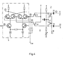
- the color separation signals R, G, R which are generated by an image signal source not shown in the figure, are fed to a coder 1, which generates a composite uncorrected color signal in accordance with a predefined television standard, for example PAL or NTSC.
- This color signal is fed to the first input of an adder 2.
- the color separation signals also become a non-additive mixing circuit 3, at the output of which a signal corresponding to the greatest brightness can be removed.
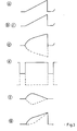
- the signals supplied to circuits 1, 2 and 3 are denoted by a and b in FIG. 3 and the signal which can be taken off at the output of circuit 3 is denoted by c. For example, sawtooth-shaped signals are used.
- the output signal of the circuit 3 is now fed to a signal processing circuit 4 which contains a low-pass element 6 and a non-linear amplifier circuit 7 and 8 each.
- the low-pass element 6 only allows signals of the lower frequency range to pass through, since measures influencing the contrast are expedient only in low-frequency image details.
- the term of the low-pass element 6 is adapted to that of the encoder 1, so that a separate term adjustment can be dispensed with.
- the band-limited signal is fed to a non-linear amplifier stage 7, in which a so-called.
- the signal is "stretched black". A signal according to d (FIG. 3) can then be removed at the output of this stage 7.
- the blanking signal A is fed to the nonlinear amplifier stage 8, which is constructed in the same way as stage 7.
- a control voltage U S t is also supplied at both stages 7 and 8.
- e Fi G. 3
- the signals d and e are now fed to the control inputs of a multiplier 9, at whose further input the signal emitted by the coder 1 is located.
- the contrast correction signal which can be taken off at the output of the multiplier stage 9 must be closed in the blanking interval as well as in the 100% white point Become zero. This can be achieved by forming the difference between the signals d and e, which takes place in the multiplier 9.
- the signal f is then fed to the second input of the adder stage 2 and added to the uncorrected signal, so that a contrast-corrected signal g can be removed at the output of the stage 2.
- FIG. 2 shows a contrast correction circuit for color television signals according to the SECAM standard, the luminance signal Y generated by a matrix not shown in the figure and the line-sequential color difference signal D B / D ⁇ being present at the input terminals 11 and 12.
- These signals with the form b are now fed to the first inputs of an adder 13 and 14, respectively.
- a signal processing circuit 4 is provided, as in FIG. 1, at whose inputs the signal X of the non-additive mixing circuit 3, clamping pulses KI, the blanking signal A and the control voltage U St are present.
- the signals d and e are also removable, which are each fed to a multiplier 16 and 17.
- the other input of the multiplier stage 16 is supplied with the luminance signal and the other input of the multiplier stage 17 with the line-sequential color difference signal D B / D R.
- signals according to f of FIG. 3 can be removed. These signals f are now each fed to the second input of the adder stages 13 and 14.
- the output signal of stage 14 is further fed to a frequency modulator 18, at the output of which the frequency-modulated color difference signal can then be removed.
- This signal and the output signal of stage 13 are now combined in a further adding stage 19, so that a contrast-corrected color television signal according to the SECAM standard can be removed at the output of stage 19.
- the output signal X of the circuit 3 and the blanking signal A is present at the terminals 21 and 22 of the stages 7 and 8, respectively. Both signals are fed via a capacitor 23 and 24 to a clamping circuit with a field effect transistor 26 and 27, respectively.
- the field effect transistors 26 and 27 are controlled by the terminal 28 with clamping pulses KI.
- the clamped signal X is now fed to a further field-effect transistor 31, which acts as a voltage-dependent resistor, while the blanking signal, which is also clamped, is fed to a field-effect transistor 32.
- the FET becomes increasingly low-resistance with increasing gate-souice voltage.
- the polarity and the magnitude of this signal voltage can be freely selected with the control voltage U S t.
- the blanking signal A passes through the same circuit as the signal X.
- the signals d and e which are treated in the same way, are fed to the positive and negative control inputs of the multiplier 9, thereby forming a difference between the signals d and e.
- This difference formation ensures that the correction signal f becomes zero in both black and white.
- This circuit also ensures that both the luminance component Y and the chrominance component C of the coded signal are evaluated equally. This does not result in any changes in saturation, which are very disadvantageous in normal black stretching.
Landscapes
- Engineering & Computer Science (AREA)
- Multimedia (AREA)
- Signal Processing (AREA)
- Processing Of Color Television Signals (AREA)
- Color Television Image Signal Generators (AREA)
Priority Applications (1)
| Application Number | Priority Date | Filing Date | Title |
|---|---|---|---|
| AT80102335T ATE3352T1 (de) | 1979-05-25 | 1980-04-30 | Verfahren und schaltung zur kontrastkorrektur von farbfernsehsignalen. |
Applications Claiming Priority (2)
| Application Number | Priority Date | Filing Date | Title |
|---|---|---|---|
| DE2921246 | 1979-05-25 | ||
| DE19792921246 DE2921246A1 (de) | 1979-05-25 | 1979-05-25 | Verfahren und schaltung zur kontrastkorrektur von farbfernsehsignalen |
Publications (2)
| Publication Number | Publication Date |
|---|---|
| EP0019735A1 true EP0019735A1 (fr) | 1980-12-10 |
| EP0019735B1 EP0019735B1 (fr) | 1983-05-11 |
Family
ID=6071699
Family Applications (1)
| Application Number | Title | Priority Date | Filing Date |
|---|---|---|---|
| EP80102335A Expired EP0019735B1 (fr) | 1979-05-25 | 1980-04-30 | Procédé et circuit pour la correction de contraste de signaux de télévision en couleur |
Country Status (5)
| Country | Link |
|---|---|
| US (1) | US4305090A (fr) |
| EP (1) | EP0019735B1 (fr) |
| JP (1) | JPS55158789A (fr) |
| AT (1) | ATE3352T1 (fr) |
| DE (2) | DE2921246A1 (fr) |
Families Citing this family (5)
| Publication number | Priority date | Publication date | Assignee | Title |
|---|---|---|---|---|
| FR2503970B1 (fr) * | 1981-04-14 | 1985-10-18 | Lgt Lab Gen Telecomm | Dispositif de correction de non-linearite videofrequence a efficacite selective et equipement de television comportant un tel dispositif |
| US5068718A (en) * | 1988-11-04 | 1991-11-26 | Fuji Photo Film Co., Ltd. | Image quality correcting system for use with an imaging apparatus |
| JP2952488B2 (ja) * | 1988-11-04 | 1999-09-27 | 富士写真フイルム 株式会社 | 撮像装置の画質補正方式 |
| US5363318A (en) * | 1992-03-23 | 1994-11-08 | Eastman Kodak Company | Method and apparatus for adaptive color characterization and calibration |
| US5394195A (en) * | 1993-06-14 | 1995-02-28 | Philips Electronics North America Corporation | Method and apparatus for performing dynamic gamma contrast control |
Citations (2)
| Publication number | Priority date | Publication date | Assignee | Title |
|---|---|---|---|---|
| US3684825A (en) * | 1971-02-19 | 1972-08-15 | Rca Corp | Contrast compression circuits |
| DE2348588A1 (de) * | 1973-09-27 | 1975-04-24 | Bosch Fernsehanlagen | Einrichtung zur gamma-korrektur von farbfernseh-uebertragungsanlagen |
Family Cites Families (4)
| Publication number | Priority date | Publication date | Assignee | Title |
|---|---|---|---|---|
| JPS5145451B2 (fr) * | 1971-10-27 | 1976-12-03 | ||
| JPS494443A (fr) * | 1972-04-25 | 1974-01-16 | ||
| US4167750A (en) * | 1975-02-20 | 1979-09-11 | Matsushita Electric Industrial Co., Ltd. | Color-difference signal modifying apparatus |
| GB1524720A (en) * | 1976-09-16 | 1978-09-13 | Marconi Co Ltd | Contrast correction arrangements |
-
1979
- 1979-05-25 DE DE19792921246 patent/DE2921246A1/de not_active Withdrawn
-
1980
- 1980-04-30 DE DE8080102335T patent/DE3063060D1/de not_active Expired
- 1980-04-30 EP EP80102335A patent/EP0019735B1/fr not_active Expired
- 1980-04-30 AT AT80102335T patent/ATE3352T1/de not_active IP Right Cessation
- 1980-05-15 US US06/149,946 patent/US4305090A/en not_active Expired - Lifetime
- 1980-05-26 JP JP6907880A patent/JPS55158789A/ja active Granted
Patent Citations (2)
| Publication number | Priority date | Publication date | Assignee | Title |
|---|---|---|---|---|
| US3684825A (en) * | 1971-02-19 | 1972-08-15 | Rca Corp | Contrast compression circuits |
| DE2348588A1 (de) * | 1973-09-27 | 1975-04-24 | Bosch Fernsehanlagen | Einrichtung zur gamma-korrektur von farbfernseh-uebertragungsanlagen |
Also Published As
| Publication number | Publication date |
|---|---|
| JPS55158789A (en) | 1980-12-10 |
| DE3063060D1 (en) | 1983-06-16 |
| ATE3352T1 (de) | 1983-05-15 |
| DE2921246A1 (de) | 1980-12-04 |
| JPH0316838B2 (fr) | 1991-03-06 |
| EP0019735B1 (fr) | 1983-05-11 |
| US4305090A (en) | 1981-12-08 |
Similar Documents
| Publication | Publication Date | Title |
|---|---|---|
| AT390860B (de) | Chrominanzsignal-verarbeitungskreis | |
| DE2636679A1 (de) | Farbfernseh-farbtastsignalgenerator | |
| DE2207536A1 (de) | Kontrastkompressionsschaltung für ein Farbfernsehsystem | |
| DE3143653C2 (fr) | ||
| DE3223605C2 (de) | Verfahren und Vorrichtung zum Verhindern des Auftretens falscher Farbsignale in Farbfernsehkameras | |
| DE2018149C3 (de) | Verfahren zur Erhöhung der Schärfe von Farbfernsehbildern und Schaltungsanordnung zur Durchführung des Verfahrens | |
| DE3620990C2 (de) | Verfahren und Schaltungsanordnung zur nichtlinearen Übertragung eines Videosignals | |
| DE2850856C2 (de) | Fernsehkameraschaltung mit einer Gamma- und einer Aperturkorrekturschaltung | |
| DE3238696A1 (de) | Farbschluesselsignalgenerator | |
| EP0554938B1 (fr) | Procédé pour la correction de contraste | |
| DE2937958C2 (de) | Verfahren zur horizontalen und vertikalen Konturkorrektur | |
| DE3412529A1 (de) | Stoersignalverminderungsschaltung fuer ein videosignal | |
| EP0019735B1 (fr) | Procédé et circuit pour la correction de contraste de signaux de télévision en couleur | |
| DE2905264A1 (de) | Schaltung zu einer farbbild-aufnahmeeinrichtung | |
| DE2237784A1 (de) | Schaltungsanordnung zur veraenderung der farbart | |
| DE2144745C3 (de) | System zur Korrektur von Farbfernsehsignalen | |
| DE3141257A1 (de) | Farbsignalverarbeitungsschaltung | |
| EP0185195B1 (fr) | Circuit de compression de blanc pour signaux vidéo | |
| DE3027054A1 (de) | Verfahren zur ableitung eines digitalen steuersignals | |
| DE2711586C3 (de) | Schaltung zur Erzeugung spezieller Effekte auf Farbfernsehbildern insbesondere zur Betitelung | |
| DE4017878A1 (de) | Verfahren und anordnung zur ableitung eines stanzsignals | |
| DE3619663A1 (de) | System zur korrektur eines luminanzsignals | |
| DE2649781B2 (de) | Kontrastkorrekturvorrichtung für ein Farbfernsehsystem mit mehreren Bildaufnahmeröhren | |
| DE3633716A1 (de) | Verfahren und schaltung zur verringerung von stoerungen durch farbnebensprechen | |
| AT200631B (de) | Empfänger für ein Farbfernsehsystem |
Legal Events
| Date | Code | Title | Description |
|---|---|---|---|
| PUAI | Public reference made under article 153(3) epc to a published international application that has entered the european phase |
Free format text: ORIGINAL CODE: 0009012 |
|
| AK | Designated contracting states |
Designated state(s): AT BE CH DE FR GB IT NL |
|
| 17P | Request for examination filed |
Effective date: 19801117 |
|
| GRAA | (expected) grant |
Free format text: ORIGINAL CODE: 0009210 |
|
| AK | Designated contracting states |
Designated state(s): AT BE CH DE FR GB IT LI NL |
|
| PG25 | Lapsed in a contracting state [announced via postgrant information from national office to epo] |
Ref country code: IT Free format text: LAPSE BECAUSE OF FAILURE TO SUBMIT A TRANSLATION OF THE DESCRIPTION OR TO PAY THE FEE WITHIN THE PRESCRIBED TIME-LIMIT;WARNING: LAPSES OF ITALIAN PATENTS WITH EFFECTIVE DATE BEFORE 2007 MAY HAVE OCCURRED AT ANY TIME BEFORE 2007. THE CORRECT EFFECTIVE DATE MAY BE DIFFERENT FROM THE ONE RECORDED. Effective date: 19830511 |
|
| REF | Corresponds to: |
Ref document number: 3352 Country of ref document: AT Date of ref document: 19830515 Kind code of ref document: T |
|
| REF | Corresponds to: |
Ref document number: 3063060 Country of ref document: DE Date of ref document: 19830616 |
|
| ET | Fr: translation filed | ||
| PLBE | No opposition filed within time limit |
Free format text: ORIGINAL CODE: 0009261 |
|
| STAA | Information on the status of an ep patent application or granted ep patent |
Free format text: STATUS: NO OPPOSITION FILED WITHIN TIME LIMIT |
|
| 26N | No opposition filed | ||
| PGFP | Annual fee paid to national office [announced via postgrant information from national office to epo] |
Ref country code: CH Payment date: 19840730 Year of fee payment: 5 |
|
| PG25 | Lapsed in a contracting state [announced via postgrant information from national office to epo] |
Ref country code: LI Effective date: 19860430 Ref country code: CH Effective date: 19860430 |
|
| REG | Reference to a national code |
Ref country code: CH Ref legal event code: PL |
|
| PGFP | Annual fee paid to national office [announced via postgrant information from national office to epo] |
Ref country code: NL Payment date: 19870430 Year of fee payment: 8 |
|
| PGFP | Annual fee paid to national office [announced via postgrant information from national office to epo] |
Ref country code: AT Payment date: 19890424 Year of fee payment: 10 |
|
| PG25 | Lapsed in a contracting state [announced via postgrant information from national office to epo] |
Ref country code: NL Effective date: 19891101 |
|
| NLV4 | Nl: lapsed or anulled due to non-payment of the annual fee | ||
| REG | Reference to a national code |
Ref country code: GB Ref legal event code: 746 |
|
| PG25 | Lapsed in a contracting state [announced via postgrant information from national office to epo] |
Ref country code: AT Effective date: 19900430 |
|
| PGFP | Annual fee paid to national office [announced via postgrant information from national office to epo] |
Ref country code: GB Payment date: 19940420 Year of fee payment: 15 |
|
| PGFP | Annual fee paid to national office [announced via postgrant information from national office to epo] |
Ref country code: FR Payment date: 19940429 Year of fee payment: 15 |
|
| PGFP | Annual fee paid to national office [announced via postgrant information from national office to epo] |
Ref country code: DE Payment date: 19940628 Year of fee payment: 15 |
|
| PGFP | Annual fee paid to national office [announced via postgrant information from national office to epo] |
Ref country code: BE Payment date: 19940715 Year of fee payment: 15 |
|
| PG25 | Lapsed in a contracting state [announced via postgrant information from national office to epo] |
Ref country code: GB Effective date: 19950430 Ref country code: BE Effective date: 19950430 |
|
| BERE | Be: lapsed |
Owner name: ROBERT BOSCH G.M.B.H. Effective date: 19950430 |
|
| PG25 | Lapsed in a contracting state [announced via postgrant information from national office to epo] |
Ref country code: FR Effective date: 19951229 |
|
| GBPC | Gb: european patent ceased through non-payment of renewal fee |
Effective date: 19950430 |
|
| PG25 | Lapsed in a contracting state [announced via postgrant information from national office to epo] |
Ref country code: DE Effective date: 19960103 |
|
| REG | Reference to a national code |
Ref country code: FR Ref legal event code: ST |