EP0016958B1 - Profilé de cadre pour fenêtre, porte ou analogue - Google Patents
Profilé de cadre pour fenêtre, porte ou analogue Download PDFInfo
- Publication number
- EP0016958B1 EP0016958B1 EP19800100913 EP80100913A EP0016958B1 EP 0016958 B1 EP0016958 B1 EP 0016958B1 EP 19800100913 EP19800100913 EP 19800100913 EP 80100913 A EP80100913 A EP 80100913A EP 0016958 B1 EP0016958 B1 EP 0016958B1
- Authority
- EP
- European Patent Office
- Prior art keywords
- inner element
- rail
- frame profile
- locking
- profile according
- Prior art date
- Legal status (The legal status is an assumption and is not a legal conclusion. Google has not performed a legal analysis and makes no representation as to the accuracy of the status listed.)
- Expired
Links
Images
Classifications
-
- E—FIXED CONSTRUCTIONS
- E06—DOORS, WINDOWS, SHUTTERS, OR ROLLER BLINDS IN GENERAL; LADDERS
- E06B—FIXED OR MOVABLE CLOSURES FOR OPENINGS IN BUILDINGS, VEHICLES, FENCES OR LIKE ENCLOSURES IN GENERAL, e.g. DOORS, WINDOWS, BLINDS, GATES
- E06B1/00—Border constructions of openings in walls, floors, or ceilings; Frames to be rigidly mounted in such openings
- E06B1/70—Sills; Thresholds
-
- E—FIXED CONSTRUCTIONS
- E06—DOORS, WINDOWS, SHUTTERS, OR ROLLER BLINDS IN GENERAL; LADDERS
- E06B—FIXED OR MOVABLE CLOSURES FOR OPENINGS IN BUILDINGS, VEHICLES, FENCES OR LIKE ENCLOSURES IN GENERAL, e.g. DOORS, WINDOWS, BLINDS, GATES
- E06B1/00—Border constructions of openings in walls, floors, or ceilings; Frames to be rigidly mounted in such openings
- E06B1/04—Frames for doors, windows, or the like to be fixed in openings
- E06B1/32—Frames composed of parts made of different materials
- E06B1/325—Frames composed of parts made of different materials comprising insulation between two metal section members
-
- E—FIXED CONSTRUCTIONS
- E06—DOORS, WINDOWS, SHUTTERS, OR ROLLER BLINDS IN GENERAL; LADDERS
- E06B—FIXED OR MOVABLE CLOSURES FOR OPENINGS IN BUILDINGS, VEHICLES, FENCES OR LIKE ENCLOSURES IN GENERAL, e.g. DOORS, WINDOWS, BLINDS, GATES
- E06B3/00—Window sashes, door leaves, or like elements for closing wall or like openings; Layout of fixed or moving closures, e.g. windows in wall or like openings; Features of rigidly-mounted outer frames relating to the mounting of wing frames
- E06B3/32—Arrangements of wings characterised by the manner of movement; Arrangements of movable wings in openings; Features of wings or frames relating solely to the manner of movement of the wing
- E06B3/34—Arrangements of wings characterised by the manner of movement; Arrangements of movable wings in openings; Features of wings or frames relating solely to the manner of movement of the wing with only one kind of movement
- E06B3/42—Sliding wings; Details of frames with respect to guiding
- E06B3/46—Horizontally-sliding wings
- E06B3/4609—Horizontally-sliding wings for windows
-
- E—FIXED CONSTRUCTIONS
- E06—DOORS, WINDOWS, SHUTTERS, OR ROLLER BLINDS IN GENERAL; LADDERS
- E06B—FIXED OR MOVABLE CLOSURES FOR OPENINGS IN BUILDINGS, VEHICLES, FENCES OR LIKE ENCLOSURES IN GENERAL, e.g. DOORS, WINDOWS, BLINDS, GATES
- E06B1/00—Border constructions of openings in walls, floors, or ceilings; Frames to be rigidly mounted in such openings
- E06B1/70—Sills; Thresholds
- E06B2001/707—Thresholds with special provision for insulation
-
- E—FIXED CONSTRUCTIONS
- E06—DOORS, WINDOWS, SHUTTERS, OR ROLLER BLINDS IN GENERAL; LADDERS
- E06B—FIXED OR MOVABLE CLOSURES FOR OPENINGS IN BUILDINGS, VEHICLES, FENCES OR LIKE ENCLOSURES IN GENERAL, e.g. DOORS, WINDOWS, BLINDS, GATES
- E06B3/00—Window sashes, door leaves, or like elements for closing wall or like openings; Layout of fixed or moving closures, e.g. windows in wall or like openings; Features of rigidly-mounted outer frames relating to the mounting of wing frames
- E06B3/04—Wing frames not characterised by the manner of movement
- E06B3/263—Frames with special provision for insulation
- E06B3/26347—Frames with special provision for insulation specially adapted for sliding doors or windows
Definitions
- the invention relates to a frame profile for a window, a door or the like, consisting of an inner element facing the interior of the room and an outer element which can be plugged in or locked, and at least one running rail, the inner element consisting of a material of poorer thermal conductivity than that Outer element.
- a frame profile is proposed in the older, not previously published European patent application 0003042 by the same applicant.
- the running rail is screwed to the inner element. The task is to create such a frame profile easier and cheaper and to make it cheaper to assemble.
- a frame profile is formed according to the preamble of claim 1 in accordance with the characterizing part of the first claim. Due to the use of a screwless intermediate member, which is connected to the outer element in a pluggable or latchable manner, and the attachment of the running rail to this intermediate member without the use of screws or other comparable connecting elements, at least the attachment of through holes for the screws or the like on the running rail is omitted , and the comparatively time-consuming process of screwing on. In this way, the assembly costs of this frame profile, but also the costs for the production of the same, can be reduced in the desired manner, because at least the installation of through holes on the running rail is unnecessary. In addition, this running rail can be exchanged relatively easily and quickly and without damaging the inner element, which is not possible when the running rail is screwed on.
- This frame profile is also suitable for self-assembly, and in addition end pieces are easier to use here than with a running rail pre-perforated at fixed intervals, where the end piece may have to be provided with additional through holes for screws.
- a further development of a frame profile with a latching connection of the running rail and the inner element provides that the running rail has two latching strips which are arranged at a distance from one another and extend in the longitudinal direction thereof, and the inner element has two correspondingly arranged and designed slot-like latching receptacles.
- the reverse arrangement of locking bars and locking receptacles would also be conceivable, but this would not be so advantageous in the case of the conventional running track design.
- continuous locking bars one could of course also provide individual locking bars arranged in an extension of one another and spaced apart. These could interact with the slot-like, continuous snap-in receptacles or with the short, slit-shaped snap-in receptacles assigned to them.
- the continuous latching strips are more expedient because their manufacture is simplest, particularly in the case of extruded or comparable rails.
- a preferred embodiment of a frame profile with at least in its central region in cross section approximately U-shaped running rail, the U-legs of which point towards the inner element, provides that the latching strips are formed by extension pieces of the two U-legs. This avoids unfavorable accumulations of material and gives you a clear and easy-to-create overall profile.
- a latching bead or the like is located at the free end of each extension piece and the two latching beads point towards one another. Accordingly, these two locking beads are located on the inwardly facing surface of the extension pieces.
- the inner element has two opposite pairs of slot-like latching receptacles, in particular of approximately the same shape and size.
- Each of the pairs of snap-in receptacles arranged and formed in a mirror image establishes the connection to the associated part, that is to the outer element on the one hand and to the running rail on the other.
- the mirror-image design in turn enables a comparatively simple design of the profile, at least in this area, and the avoidance of undesirable material accumulations.
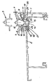
- the frame profile consists of the inner element 1 facing the interior of the room, which is fastened in a latching manner to an outer element 2 and carries the running rail 3.
- the running rail 3 After the running rail 3 is connected to the inner element 1 in a latching or snap-in manner, the latter constitutes a screwless intermediate member between the outer element 2 and the running rail 3.
- the running rail 3 has two spacing strips 4 and 5, which extend in the longitudinal direction thereof. They are formed by extension pieces of the two U-legs 6 and 7 of the rail 3, which is approximately U-shaped in cross section in its central region. At the transition from each U-leg to its associated locking bar, a laterally extending support bar 8 or 9 is formed. At the free end of the two locking bars there is a locking bead 10 and 11, respectively.
- Each latching bead engages under a counterbead 12 or 13 of an upwardly projecting bar 14 or 15 of the inner element 1.
- the latter and a further bar 16 and 17 which are parallel thereto form a latching receptacle 19 and 20 with a central web 18.
- latching receptacles 19 and 20 there are two further latching receptacles 21 and 22, in which a latching bar 23 and 24 of the outer element 2 engages.
- the locking receptacles 19, 20, 21 and 22 do not necessarily have to be of the same design and arranged opposite one another, but it is with regard to the manufacture and profile design of the inner element of Vorieil, if one chooses the design in this way.
- the outer element 2 is designed as a so-called open pipe sleeper. Like the running rail 3, this is an extruded profile, preferably made of aluminum. In a manner not shown, the outer element 2 can be stiffened in a latching manner with at least one short or a continuous connecting profile of approximately the same length in order to be able to withstand particularly high loads and / or for other reasons.
- the running rail 3 was also drawn in the unmounted state.
- an inner element made of a material with poorer thermal conductivity in relation to the material of the outer element, on the one hand avoiding condensation on the inside of the frame profile and on the other hand also heat losses due to a cold bridge.
- the inner element 1 is made of plastic, for example, this is not only advantageous in terms of preventing condensation or a cold bridge, but also with regard to the snap-in and latching connection with the outer profile on the one hand and the running rail 3 on the other.
- plastic generally not only has a poorer thermal conductivity but also a lower strength than steel, it is less suitable than metal for manufacturing, in particular shaping the running track on the inner element.
- the running track is preferably made of aluminum or stainless steel, so that it can withstand the special static and rolling stresses.
Claims (5)
Applications Claiming Priority (2)
| Application Number | Priority Date | Filing Date | Title |
|---|---|---|---|
| DE19797908753 DE7908753U1 (de) | 1979-03-28 | 1979-03-28 | Rahmenprofil fuer ein fenster, eine tuer o.dgl. |
| DE7908753U | 1979-03-28 |
Publications (2)
| Publication Number | Publication Date |
|---|---|
| EP0016958A1 EP0016958A1 (fr) | 1980-10-15 |
| EP0016958B1 true EP0016958B1 (fr) | 1982-06-23 |
Family
ID=6702485
Family Applications (1)
| Application Number | Title | Priority Date | Filing Date |
|---|---|---|---|
| EP19800100913 Expired EP0016958B1 (fr) | 1979-03-28 | 1980-02-25 | Profilé de cadre pour fenêtre, porte ou analogue |
Country Status (3)
| Country | Link |
|---|---|
| EP (1) | EP0016958B1 (fr) |
| AT (1) | AT376763B (fr) |
| DE (1) | DE7908753U1 (fr) |
Cited By (2)
| Publication number | Priority date | Publication date | Assignee | Title |
|---|---|---|---|---|
| US10186350B2 (en) | 2016-07-26 | 2019-01-22 | General Cable Technologies Corporation | Cable having shielding tape with conductive shielding segments |
| US10517198B1 (en) | 2018-06-14 | 2019-12-24 | General Cable Technologies Corporation | Cable having shielding tape with conductive shielding segments |
Families Citing this family (8)
| Publication number | Priority date | Publication date | Assignee | Title |
|---|---|---|---|---|
| DE7908753U1 (de) * | 1979-03-28 | 1979-07-05 | Gretsch-Unitas Gmbh Baubeschlagfabrik, 7257 Ditzingen | Rahmenprofil fuer ein fenster, eine tuer o.dgl. |
| US4548015A (en) * | 1983-07-25 | 1985-10-22 | Harold Switzgable | Thermally broken insulation support structure |
| IT1254553B (it) * | 1992-03-24 | 1995-09-25 | Struttura di profilati con taglio termico, per la realizzazione di infissi ad ante scorrevoli. | |
| DE9318973U1 (de) * | 1993-12-10 | 1994-02-10 | Siegenia Frank Kg | Bodenschwelle bzw. Abdeckprofil für Blendrahmen von Schiebe- oder Hebe-Schiebefenstern und -türen o.dgl. |
| DE29612478U1 (de) * | 1996-07-18 | 1997-11-13 | Niemann Hans Dieter | Türschwellenprofil |
| DE29618677U1 (de) * | 1996-10-26 | 1996-12-12 | Gretsch Unitas Gmbh | Schiebebeschlag für Türen, Fenster o.dgl. |
| DE29818304U1 (de) | 1998-10-15 | 1998-12-24 | Siegenia Frank Kg | Mehrzweck-Bodenschwelle |
| ES2235713T3 (es) | 1999-05-31 | 2005-07-16 | Gretsch Unitas Gmbh Baubeschlage | Traviesa para puerta de edificio asi como puerta de edificio. |
Family Cites Families (6)
| Publication number | Priority date | Publication date | Assignee | Title |
|---|---|---|---|---|
| DE7018201U (de) * | 1970-05-15 | 1971-06-03 | Hueck Fa E | Schiebefenster. |
| FR2164996A5 (fr) * | 1971-12-14 | 1973-08-03 | Pantz Laon Const Metal | |
| DE2330370C3 (de) * | 1972-06-14 | 1979-11-15 | Adam Sarrebourg Mosel Fey (Frankreich) | Schiebefenster bzw. Schiebetür |
| AT346559B (de) * | 1975-04-18 | 1978-11-10 | Semperit Ag | Abdeckschiene fuer fensterbaenke, tuerschwellen od.dgl. |
| DE2801596A1 (de) * | 1978-01-14 | 1979-07-19 | Gretsch Unitas Gmbh | Rahmenprofil fuer ein fenster, eine tuer o.dgl. |
| DE7908753U1 (de) * | 1979-03-28 | 1979-07-05 | Gretsch-Unitas Gmbh Baubeschlagfabrik, 7257 Ditzingen | Rahmenprofil fuer ein fenster, eine tuer o.dgl. |
-
1979
- 1979-03-28 DE DE19797908753 patent/DE7908753U1/de not_active Expired
-
1980
- 1980-02-25 EP EP19800100913 patent/EP0016958B1/fr not_active Expired
- 1980-03-04 AT AT117880A patent/AT376763B/de not_active IP Right Cessation
Cited By (2)
| Publication number | Priority date | Publication date | Assignee | Title |
|---|---|---|---|---|
| US10186350B2 (en) | 2016-07-26 | 2019-01-22 | General Cable Technologies Corporation | Cable having shielding tape with conductive shielding segments |
| US10517198B1 (en) | 2018-06-14 | 2019-12-24 | General Cable Technologies Corporation | Cable having shielding tape with conductive shielding segments |
Also Published As
| Publication number | Publication date |
|---|---|
| DE7908753U1 (de) | 1979-07-05 |
| AT376763B (de) | 1984-12-27 |
| ATA117880A (de) | 1984-05-15 |
| EP0016958A1 (fr) | 1980-10-15 |
Similar Documents
| Publication | Publication Date | Title |
|---|---|---|
| EP0652332B1 (fr) | Panneau calorifuge fait en matière isolante fibreuse ou liège | |
| DE2930470C2 (fr) | ||
| EP0016958B1 (fr) | Profilé de cadre pour fenêtre, porte ou analogue | |
| CH634629A5 (en) | Roller-shutter slat | |
| DE2812128C3 (de) | Wärmeisolierender Profilkörper | |
| DE2935158B2 (de) | Stranggepreßtes Bauelement zum Aufbau von Wänden, insbesondere von Kraftfahrzeugen | |
| DE2746434C3 (de) | Verbundprofil für Fenster, Türen o.dgl. - aus zwei Metallprofilen und aus einem geschlossenen Hohlprofil aus wärmedämmendem Werkstoff | |
| DE19617269A1 (de) | Mehrteilige Fassadenklammer | |
| DE2256045A1 (de) | Gelaender | |
| DE3603221C2 (fr) | ||
| AT391515B (de) | Waermegedaemmtes verbundprofil | |
| CH634894A5 (en) | Roller shutter or roller door | |
| EP0620353B1 (fr) | Profil pour le renforcement extérieur d'un montant de fenêtre | |
| CH664625A5 (de) | Kuehlschrank. | |
| DE2559336C3 (de) | Zusammengesetztes, wärmeisolierendes Profil für Fenster, Türen o.dgl | |
| DE3219138A1 (de) | Paneelverbinder | |
| EP0956405B1 (fr) | Ensemble d'un moyen de suspension universel et un rail profile en c | |
| LU502438B1 (de) | Profilrahmensysteme für schiebeelemente | |
| EP1460214B1 (fr) | Crémone en plastique | |
| DE2334860C3 (de) | Zur Bildung von Regalen dienende Trennwand | |
| EP0045460B1 (fr) | Elément porteur en forme de barre profilée pour un support d'enduit | |
| DE19902400A1 (de) | Gebäudefenster oder Gebäudefenstertür sowie Blendrahmen für ein solches Fenster bzw. eine solche Fenstertür | |
| EP4296444A2 (fr) | Dispositif de montage | |
| DE1779590C2 (de) | Vorbauschiene für Vorhangschienen | |
| DE1683371C3 (de) | Rahmen für Fenster und Türen mit einem hölzernen Grundprofll und mit einer ProfilauBenverkleidung |
Legal Events
| Date | Code | Title | Description |
|---|---|---|---|
| PUAI | Public reference made under article 153(3) epc to a published international application that has entered the european phase |
Free format text: ORIGINAL CODE: 0009012 |
|
| AK | Designated contracting states |
Designated state(s): BE CH FR |
|
| 17P | Request for examination filed |
Effective date: 19810310 |
|
| GRAA | (expected) grant |
Free format text: ORIGINAL CODE: 0009210 |
|
| AK | Designated contracting states |
Designated state(s): BE CH FR |
|
| PGFP | Annual fee paid to national office [announced via postgrant information from national office to epo] |
Ref country code: FR Payment date: 19890112 Year of fee payment: 10 |
|
| PGFP | Annual fee paid to national office [announced via postgrant information from national office to epo] |
Ref country code: CH Payment date: 19890118 Year of fee payment: 10 |
|
| PGFP | Annual fee paid to national office [announced via postgrant information from national office to epo] |
Ref country code: BE Payment date: 19890119 Year of fee payment: 10 |
|
| PG25 | Lapsed in a contracting state [announced via postgrant information from national office to epo] |
Ref country code: BE Effective date: 19900228 Ref country code: CH Effective date: 19900228 |
|
| BERE | Be: lapsed |
Owner name: GRETSCH-UNITAS G.M.B.H. BAUBESCHLAGFABRIK Effective date: 19900228 |
|
| PG25 | Lapsed in a contracting state [announced via postgrant information from national office to epo] |
Ref country code: FR Effective date: 19901031 |
|
| REG | Reference to a national code |
Ref country code: CH Ref legal event code: PL |
|
| REG | Reference to a national code |
Ref country code: FR Ref legal event code: ST |
|
| PLBE | No opposition filed within time limit |
Free format text: ORIGINAL CODE: 0009261 |
|
| STAA | Information on the status of an ep patent application or granted ep patent |
Free format text: STATUS: NO OPPOSITION FILED WITHIN TIME LIMIT |