EP0016958B1 - Frame section for a window, a door or the like - Google Patents
Frame section for a window, a door or the like Download PDFInfo
- Publication number
- EP0016958B1 EP0016958B1 EP19800100913 EP80100913A EP0016958B1 EP 0016958 B1 EP0016958 B1 EP 0016958B1 EP 19800100913 EP19800100913 EP 19800100913 EP 80100913 A EP80100913 A EP 80100913A EP 0016958 B1 EP0016958 B1 EP 0016958B1
- Authority
- EP
- European Patent Office
- Prior art keywords
- inner element
- rail
- frame profile
- locking
- profile according
- Prior art date
- Legal status (The legal status is an assumption and is not a legal conclusion. Google has not performed a legal analysis and makes no representation as to the accuracy of the status listed.)
- Expired
Links
Images
Classifications
-
- E—FIXED CONSTRUCTIONS
- E06—DOORS, WINDOWS, SHUTTERS, OR ROLLER BLINDS IN GENERAL; LADDERS
- E06B—FIXED OR MOVABLE CLOSURES FOR OPENINGS IN BUILDINGS, VEHICLES, FENCES OR LIKE ENCLOSURES IN GENERAL, e.g. DOORS, WINDOWS, BLINDS, GATES
- E06B1/00—Border constructions of openings in walls, floors, or ceilings; Frames to be rigidly mounted in such openings
- E06B1/70—Sills; Thresholds
-
- E—FIXED CONSTRUCTIONS
- E06—DOORS, WINDOWS, SHUTTERS, OR ROLLER BLINDS IN GENERAL; LADDERS
- E06B—FIXED OR MOVABLE CLOSURES FOR OPENINGS IN BUILDINGS, VEHICLES, FENCES OR LIKE ENCLOSURES IN GENERAL, e.g. DOORS, WINDOWS, BLINDS, GATES
- E06B1/00—Border constructions of openings in walls, floors, or ceilings; Frames to be rigidly mounted in such openings
- E06B1/04—Frames for doors, windows, or the like to be fixed in openings
- E06B1/32—Frames composed of parts made of different materials
- E06B1/325—Frames composed of parts made of different materials comprising insulation between two metal section members
-
- E—FIXED CONSTRUCTIONS
- E06—DOORS, WINDOWS, SHUTTERS, OR ROLLER BLINDS IN GENERAL; LADDERS
- E06B—FIXED OR MOVABLE CLOSURES FOR OPENINGS IN BUILDINGS, VEHICLES, FENCES OR LIKE ENCLOSURES IN GENERAL, e.g. DOORS, WINDOWS, BLINDS, GATES
- E06B3/00—Window sashes, door leaves, or like elements for closing wall or like openings; Layout of fixed or moving closures, e.g. windows in wall or like openings; Features of rigidly-mounted outer frames relating to the mounting of wing frames
- E06B3/32—Arrangements of wings characterised by the manner of movement; Arrangements of movable wings in openings; Features of wings or frames relating solely to the manner of movement of the wing
- E06B3/34—Arrangements of wings characterised by the manner of movement; Arrangements of movable wings in openings; Features of wings or frames relating solely to the manner of movement of the wing with only one kind of movement
- E06B3/42—Sliding wings; Details of frames with respect to guiding
- E06B3/46—Horizontally-sliding wings
- E06B3/4609—Horizontally-sliding wings for windows
-
- E—FIXED CONSTRUCTIONS
- E06—DOORS, WINDOWS, SHUTTERS, OR ROLLER BLINDS IN GENERAL; LADDERS
- E06B—FIXED OR MOVABLE CLOSURES FOR OPENINGS IN BUILDINGS, VEHICLES, FENCES OR LIKE ENCLOSURES IN GENERAL, e.g. DOORS, WINDOWS, BLINDS, GATES
- E06B1/00—Border constructions of openings in walls, floors, or ceilings; Frames to be rigidly mounted in such openings
- E06B1/70—Sills; Thresholds
- E06B2001/707—Thresholds with special provision for insulation
-
- E—FIXED CONSTRUCTIONS
- E06—DOORS, WINDOWS, SHUTTERS, OR ROLLER BLINDS IN GENERAL; LADDERS
- E06B—FIXED OR MOVABLE CLOSURES FOR OPENINGS IN BUILDINGS, VEHICLES, FENCES OR LIKE ENCLOSURES IN GENERAL, e.g. DOORS, WINDOWS, BLINDS, GATES
- E06B3/00—Window sashes, door leaves, or like elements for closing wall or like openings; Layout of fixed or moving closures, e.g. windows in wall or like openings; Features of rigidly-mounted outer frames relating to the mounting of wing frames
- E06B3/04—Wing frames not characterised by the manner of movement
- E06B3/263—Frames with special provision for insulation
- E06B3/26347—Frames with special provision for insulation specially adapted for sliding doors or windows
Definitions
- the invention relates to a frame profile for a window, a door or the like, consisting of an inner element facing the interior of the room and an outer element which can be plugged in or locked, and at least one running rail, the inner element consisting of a material of poorer thermal conductivity than that Outer element.
- a frame profile is proposed in the older, not previously published European patent application 0003042 by the same applicant.
- the running rail is screwed to the inner element. The task is to create such a frame profile easier and cheaper and to make it cheaper to assemble.
- a frame profile is formed according to the preamble of claim 1 in accordance with the characterizing part of the first claim. Due to the use of a screwless intermediate member, which is connected to the outer element in a pluggable or latchable manner, and the attachment of the running rail to this intermediate member without the use of screws or other comparable connecting elements, at least the attachment of through holes for the screws or the like on the running rail is omitted , and the comparatively time-consuming process of screwing on. In this way, the assembly costs of this frame profile, but also the costs for the production of the same, can be reduced in the desired manner, because at least the installation of through holes on the running rail is unnecessary. In addition, this running rail can be exchanged relatively easily and quickly and without damaging the inner element, which is not possible when the running rail is screwed on.
- This frame profile is also suitable for self-assembly, and in addition end pieces are easier to use here than with a running rail pre-perforated at fixed intervals, where the end piece may have to be provided with additional through holes for screws.
- a further development of a frame profile with a latching connection of the running rail and the inner element provides that the running rail has two latching strips which are arranged at a distance from one another and extend in the longitudinal direction thereof, and the inner element has two correspondingly arranged and designed slot-like latching receptacles.
- the reverse arrangement of locking bars and locking receptacles would also be conceivable, but this would not be so advantageous in the case of the conventional running track design.
- continuous locking bars one could of course also provide individual locking bars arranged in an extension of one another and spaced apart. These could interact with the slot-like, continuous snap-in receptacles or with the short, slit-shaped snap-in receptacles assigned to them.
- the continuous latching strips are more expedient because their manufacture is simplest, particularly in the case of extruded or comparable rails.
- a preferred embodiment of a frame profile with at least in its central region in cross section approximately U-shaped running rail, the U-legs of which point towards the inner element, provides that the latching strips are formed by extension pieces of the two U-legs. This avoids unfavorable accumulations of material and gives you a clear and easy-to-create overall profile.
- a latching bead or the like is located at the free end of each extension piece and the two latching beads point towards one another. Accordingly, these two locking beads are located on the inwardly facing surface of the extension pieces.
- the inner element has two opposite pairs of slot-like latching receptacles, in particular of approximately the same shape and size.
- Each of the pairs of snap-in receptacles arranged and formed in a mirror image establishes the connection to the associated part, that is to the outer element on the one hand and to the running rail on the other.
- the mirror-image design in turn enables a comparatively simple design of the profile, at least in this area, and the avoidance of undesirable material accumulations.
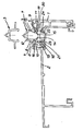
- the frame profile consists of the inner element 1 facing the interior of the room, which is fastened in a latching manner to an outer element 2 and carries the running rail 3.
- the running rail 3 After the running rail 3 is connected to the inner element 1 in a latching or snap-in manner, the latter constitutes a screwless intermediate member between the outer element 2 and the running rail 3.
- the running rail 3 has two spacing strips 4 and 5, which extend in the longitudinal direction thereof. They are formed by extension pieces of the two U-legs 6 and 7 of the rail 3, which is approximately U-shaped in cross section in its central region. At the transition from each U-leg to its associated locking bar, a laterally extending support bar 8 or 9 is formed. At the free end of the two locking bars there is a locking bead 10 and 11, respectively.
- Each latching bead engages under a counterbead 12 or 13 of an upwardly projecting bar 14 or 15 of the inner element 1.
- the latter and a further bar 16 and 17 which are parallel thereto form a latching receptacle 19 and 20 with a central web 18.
- latching receptacles 19 and 20 there are two further latching receptacles 21 and 22, in which a latching bar 23 and 24 of the outer element 2 engages.
- the locking receptacles 19, 20, 21 and 22 do not necessarily have to be of the same design and arranged opposite one another, but it is with regard to the manufacture and profile design of the inner element of Vorieil, if one chooses the design in this way.
- the outer element 2 is designed as a so-called open pipe sleeper. Like the running rail 3, this is an extruded profile, preferably made of aluminum. In a manner not shown, the outer element 2 can be stiffened in a latching manner with at least one short or a continuous connecting profile of approximately the same length in order to be able to withstand particularly high loads and / or for other reasons.
- the running rail 3 was also drawn in the unmounted state.
- an inner element made of a material with poorer thermal conductivity in relation to the material of the outer element, on the one hand avoiding condensation on the inside of the frame profile and on the other hand also heat losses due to a cold bridge.
- the inner element 1 is made of plastic, for example, this is not only advantageous in terms of preventing condensation or a cold bridge, but also with regard to the snap-in and latching connection with the outer profile on the one hand and the running rail 3 on the other.
- plastic generally not only has a poorer thermal conductivity but also a lower strength than steel, it is less suitable than metal for manufacturing, in particular shaping the running track on the inner element.
- the running track is preferably made of aluminum or stainless steel, so that it can withstand the special static and rolling stresses.
Description
Die Erfindung bezieht sich auf ein Rahmenprofil für ein Fenster, eine Tür od. dgl., bestehend aus einem dem Rauminnern zugekehrten Innenelement und einem steck- oder verastbar damit verbundenen Außenelement sowie mindestens einer Laufschiene, wobei das Innenelement aus einem Werkstoff schlechterer Wärmeleitfähigkeit besteht als das Außenelement. Ein derartiges Rahmenprofil wird in der älteren, nicht vorveröffentlichten europäischen Patentanmeldung 0003042 der gleichen Anmelderin vorgeschlagen. Bei diesem Rahmenprofil ist die Laufschiene an dem Innenelement angeschraubt. Es liegt die Aufgabe vor, ein derartiges Rahmenprofil einfacher und preiswerter zu erstellen und seine Montage zu verbilligen.The invention relates to a frame profile for a window, a door or the like, consisting of an inner element facing the interior of the room and an outer element which can be plugged in or locked, and at least one running rail, the inner element consisting of a material of poorer thermal conductivity than that Outer element. Such a frame profile is proposed in the older, not previously published European patent application 0003042 by the same applicant. In this frame profile, the running rail is screwed to the inner element. The task is to create such a frame profile easier and cheaper and to make it cheaper to assemble.
Zur Lösung dieser Aufgabe wird ein Rahmenprofil gemäß dem Oberbegriff des Anspruchs 1 entsprechend dem kennzeichnenden Teil des ersten Anspruchs ausgebildet. Durch die Verwendung eines schraubenlosen Zwischenglieds, welches steck- oder verrastbar mit dem Außenelement verbunden ist, und die Anbringung der Laufschiene an diesem Zwischenglied ohne Verwendung von Schrauben oder anderen vergleichbaren Verbindungselementen entfällt zumindest die Anbringung von Durchsteckbohrungen für die Schrauben od. dgl. an der Laufschiene, und der vergleichsweise zeitaufwendige Arbeitsgang des Anschraubens. Damit lasen sich in der angestrebten Weise die Montagekosten dieses Rahmenprofils, aber auch die Kosten für die Herstellung desselben reduzieren, weil zumindest die Anbringung von Durchsteckbohrungen an der Laufschiene entbehrlich ist. Es kommt noch hinzu, daß diese Laufschiene relativ einfach und rasch sowie ohne Beschädigung des Innenelements ausgetauscht werden kann, was beim Anschrauben der Laufschiene nicht möglich ist.To achieve this object, a frame profile is formed according to the preamble of
Damit bietet sich dieses Rahmenprofil auch für die Selbstmontage an, und außerdem sind Endstücke hier leichter zu verwerten als bei einer in festen Abständen vorgelochten Laufschiene, wo das Endstück gegebenenfalls mit zusätzlichen Durchstecklöcher für Schrauben versehen werden muß.This frame profile is also suitable for self-assembly, and in addition end pieces are easier to use here than with a running rail pre-perforated at fixed intervals, where the end piece may have to be provided with additional through holes for screws.
Eine Weiterbildung eines Rahmenprofils mit einer rastenden Verbindung von Laufschiene und Innenelement sieht vor, daß die Laufschiene zwei im Abstand voneinander angeordnete, sich in deren Längsrichtung erstreckende Verrastleisten, und das Innenelement zwei entsprechend angeordnete und ausgebildete schlitzartige Rastaufnahmen besitzt. Denkbar wäre natürlich auch die umgekehrte Anordnung von Rastleisten und Rastaufnahmen, jedoch wäre diese bei der üblichen Laufschienenausbildung nicht so vorteilhaft. An Stelle von durchgehenden Verrastleisten könnte man natürlich auch einzelne, in Verlängerung voneinander und im Abstand angeordnete Verraststege vorsehen. Diese könnten mit den sclllitzartigen, durchgehenden Rastaufnahmen oder aber ihnen jeweils zugeordneten kurzen, schlitzförmigen Rastaufnahmen zusammenwirken. Zweckmäßiger sind jedoch die durchgehenden Verrastleisten, weil ihre Herstellung insbesondere bei stranggepreßten oder in vergleichbarer Weise hergestellten Laufschienen an einfachsten ist.A further development of a frame profile with a latching connection of the running rail and the inner element provides that the running rail has two latching strips which are arranged at a distance from one another and extend in the longitudinal direction thereof, and the inner element has two correspondingly arranged and designed slot-like latching receptacles. Of course, the reverse arrangement of locking bars and locking receptacles would also be conceivable, but this would not be so advantageous in the case of the conventional running track design. Instead of continuous locking bars, one could of course also provide individual locking bars arranged in an extension of one another and spaced apart. These could interact with the slot-like, continuous snap-in receptacles or with the short, slit-shaped snap-in receptacles assigned to them. However, the continuous latching strips are more expedient because their manufacture is simplest, particularly in the case of extruded or comparable rails.
Eine bevorzugte Ausführung eines Rahmenprofils mit einer wenigstens in ihrem Mittelbereich im Querschnitt etwa U-förmigen Laufschiene, deren U-Schenkel gegen das innenelement weisen, sieht vor, daß die Verrastleisten durch Verlängerungsstücke der beiden U-Schenkel gebildet sind. Man vermeidet dadurch ungünstige Materialanhäufungen und bekommt so ein klares und einfach herzusteHendes Gesamtprofil.A preferred embodiment of a frame profile with at least in its central region in cross section approximately U-shaped running rail, the U-legs of which point towards the inner element, provides that the latching strips are formed by extension pieces of the two U-legs. This avoids unfavorable accumulations of material and gives you a clear and easy-to-create overall profile.
Eine andere Variante der Erfindung sieht vor, daß sich am freien Ende jedes Verlängerungsstücks ein Verrastwulst od. dgl. befindet und die beiden Verrastwulste gegeneinander weisen. Demnach befinden sich also diese beiden Verrastwulste an der jeweils nach innen weisenden Fläche der Verlängerungsstücke.Another variant of the invention provides that a latching bead or the like is located at the free end of each extension piece and the two latching beads point towards one another. Accordingly, these two locking beads are located on the inwardly facing surface of the extension pieces.
Bei einem Rahmenprofil mit einer rastenden Verbindung von Innen- und Außenelement wird in weiterer Ausbildung der Erfindung vorgeschlagen, daß das Innenelement zwei einander gegenüberliegende Paare schlitzartiger Rastaufnahmen insbesondere etwa gleicher Form und Größe aufweist. Jedes der spiegelbildlich angeordneten und ausgebildeten Rastaufnahmepaare stellt die Verbindung zum zugeordneten Teil, also zum Außenelement einerseits und zur Laufschiene andererseits her. Die spiegelbildliche Gestaltung ermöglicht ihrerseits eine zumindest in diesem Bereich vergleichsweise einfache Ausbildung des Profils und die Vermeidung unerwünschter Materialanhäufungen.In a frame profile with a latching connection between the inner and outer element, it is proposed in a further embodiment of the invention that the inner element has two opposite pairs of slot-like latching receptacles, in particular of approximately the same shape and size. Each of the pairs of snap-in receptacles arranged and formed in a mirror image establishes the connection to the associated part, that is to the outer element on the one hand and to the running rail on the other. The mirror-image design in turn enables a comparatively simple design of the profile, at least in this area, and the avoidance of undesirable material accumulations.
In der Zeichnung ist ein Ausführungsbeispiel der Erfindung in einer Stirnansicht gezeigt.In the drawing, an embodiment of the invention is shown in an end view.
Das Rahmenprofil besteht aus dem dem Rauminnern zugekehrten Innenelement 1, welches verrastend an einem Außenelement 2 befestigt ist und die Laufschiene 3 trägt. Nachdem auch die Laufschiene 3 verrastend oder schnappend mit dem Innenelement 1 verbunden ist, stellt letzteres ein schraubenloses Zwischenglied zwischen dem Außenelement 2 und der Laufschiene 3 dar. Die Laufschiene 3 besitzt zwei im Abstand voneinander angeordnete, sich in deren Längsrichtung erstreckende Verrastleisten 4 und 5. Sie sind durch Verlängerungsstücke der beiden U-Schenkel 6 und 7 der in ihrem Mittelbereich im Querschnitt etwa U-förmigen Laufschiene 3 gebildet. Am Übergang von jedem U-Schenkel zu seiner zugeordneten Verrastleiste ist je eine, sich seitlich nach außen erstreckende Stützleiste 8 bzw. 9 angeformt. Am freien Ende der beiden Verrastleisten befindet sich je ein Verrastwulst 10 bzw. 11. Sie sind an der Innenfläche ihrer Verrastleiste angeformt und weisen gegeneinander. Jeder Verrastwulst untergreift einen Gegenwulst 12 bzw. 13 einer nach oben ragenden Leiste 14 bzw. 15 des Innenelements 1. Letzteres und eine weitere, dazu parallele Leiste 16 bzw. 17, bilden mit einem Mittelsteg 18 eine Verrastaufnahme 19 bzw. 20.The frame profile consists of the
Spiegelbildlich zu den beiden Verrastaufnahmen 19 und 20 liegen zwei weitere Verrastaufnahmen 21 bzw. 22, in welche eine Verrastleiste 23 bzw. 24 des Außenelements 2 eingreift. Die Verrastaufnahmen 19, 20, 21 und 22 müssen nicht notwendigerweise gleich ausgebildet und einander gegenüberliegend angeordnet sein, jedoch ist es im Hinblick auf die Fertigung und Profilgestaltung des Innenelements von Vorieil, wenn man die Gestaltung in dieser Art wählt.In mirror image of the two
Das Außenelement 2 ist als sogenannte offene Rohrschwelle ausgebildet. Dabei handelt es sich, ebenso wie bei der Laufschiene 3, um ein stranggepreßtes, vorzugsweise aus Aluminium hergestelltes Profil. In nicht dargestellter Weise kann das Außenelement 2 verrastend mit wenigstens einem kurzen oder einem durchgehenden etwa gleichlangen Verbindungsprofil versteift werden, um auch besonders hohe Belastungen standhalten zu können und/oder auch aus anderen Gründen.The
Zur Verdeutlichung wurde die Laufschiene 3 auch noch in unmontiertem Zustand gezeichnet. Durch die Verwendung eines Innenelements aus einem Werkstoff schlechterer Wärmeleitfähigkeit in bezug auf den Werkstoff des Außenelements vermeidet man einerseits Schwitzwasserbildung an der Innenseite des Rahmenprofils und andererseits auch Wärmeverluste auf Grund einer Kältebrücke. Wenn man das Innenelement 1 beispielsweise aus Kunststoff herstellt, so ist das nicht nur im Hinblick auf die Verhinderung von Schwitzwasserbiidung bzw. einer Kältebrücke von Vorteil, sondern auch bezüglich der schnappenden und rastenden Verbindung mit dem Außenprofil einerseits und der Laufschiene 3 andererseits. Weil Kunststoff in der Regel nicht nur eine schlechtere Wärmeleitfähigkeit sondern auch eine geringere Festigkeit besitzt als Stahl ist er für die Herstellung, insbesondere Ausformung der Laufschiene am Innenelement weniger geeignet als Metall. Aus diesem Grunde wird die Laufschiene vorzugsweise aus Aluminium oder Edelstahl gefertigt, so daß sie den besonderen statischen und Abrollbeanspruchungen sicher standhält.For the sake of clarity, the running
Claims (5)
Applications Claiming Priority (2)
| Application Number | Priority Date | Filing Date | Title |
|---|---|---|---|
| DE19797908753 DE7908753U1 (en) | 1979-03-28 | 1979-03-28 | FRAME PROFILE FOR A WINDOW, A DOOR OR DGL. |
| DE7908753U | 1979-03-28 |
Publications (2)
| Publication Number | Publication Date |
|---|---|
| EP0016958A1 EP0016958A1 (en) | 1980-10-15 |
| EP0016958B1 true EP0016958B1 (en) | 1982-06-23 |
Family
ID=6702485
Family Applications (1)
| Application Number | Title | Priority Date | Filing Date |
|---|---|---|---|
| EP19800100913 Expired EP0016958B1 (en) | 1979-03-28 | 1980-02-25 | Frame section for a window, a door or the like |
Country Status (3)
| Country | Link |
|---|---|
| EP (1) | EP0016958B1 (en) |
| AT (1) | AT376763B (en) |
| DE (1) | DE7908753U1 (en) |
Cited By (2)
| Publication number | Priority date | Publication date | Assignee | Title |
|---|---|---|---|---|
| US10186350B2 (en) | 2016-07-26 | 2019-01-22 | General Cable Technologies Corporation | Cable having shielding tape with conductive shielding segments |
| US10517198B1 (en) | 2018-06-14 | 2019-12-24 | General Cable Technologies Corporation | Cable having shielding tape with conductive shielding segments |
Families Citing this family (8)
| Publication number | Priority date | Publication date | Assignee | Title |
|---|---|---|---|---|
| DE7908753U1 (en) * | 1979-03-28 | 1979-07-05 | Gretsch-Unitas Gmbh Baubeschlagfabrik, 7257 Ditzingen | FRAME PROFILE FOR A WINDOW, A DOOR OR DGL. |
| US4548015A (en) * | 1983-07-25 | 1985-10-22 | Harold Switzgable | Thermally broken insulation support structure |
| IT1254553B (en) * | 1992-03-24 | 1995-09-25 | STRUCTURE OF PROFILES WITH THERMAL CUT, FOR THE REALIZATION OF SLIDING DOOR WINDOWS. | |
| DE9318973U1 (en) * | 1993-12-10 | 1994-02-10 | Siegenia Frank Kg | Threshold or cover profile for blind frames of sliding or lifting-sliding windows and doors or the like. |
| DE29612478U1 (en) * | 1996-07-18 | 1997-11-13 | Niemann Hans Dieter | Door sill profile |
| DE29618677U1 (en) * | 1996-10-26 | 1996-12-12 | Gretsch Unitas Gmbh | Sliding hardware for doors, windows or the like. |
| DE29818304U1 (en) | 1998-10-15 | 1998-12-24 | Siegenia Frank Kg | Multi-purpose threshold |
| ATE288019T1 (en) | 1999-05-31 | 2005-02-15 | Gretsch Unitas Gmbh | THRESHOLD PROFILE FOR BUILDING DOORS AND BUILDING DOORS |
Family Cites Families (6)
| Publication number | Priority date | Publication date | Assignee | Title |
|---|---|---|---|---|
| DE7018201U (en) * | 1970-05-15 | 1971-06-03 | Hueck Fa E | SLIDING WINDOW. |
| FR2164996A5 (en) * | 1971-12-14 | 1973-08-03 | Pantz Laon Const Metal | |
| DE2330370C3 (en) * | 1972-06-14 | 1979-11-15 | Adam Sarrebourg Mosel Fey (Frankreich) | Sliding window or sliding door |
| AT346559B (en) * | 1975-04-18 | 1978-11-10 | Semperit Ag | COVER RAIL FOR WINDOW SILLS, DOOR SILLS OR DGL. |
| DE2801596A1 (en) * | 1978-01-14 | 1979-07-19 | Gretsch Unitas Gmbh | FRAME PROFILE FOR A WINDOW, A DOOR OR DGL. |
| DE7908753U1 (en) * | 1979-03-28 | 1979-07-05 | Gretsch-Unitas Gmbh Baubeschlagfabrik, 7257 Ditzingen | FRAME PROFILE FOR A WINDOW, A DOOR OR DGL. |
-
1979
- 1979-03-28 DE DE19797908753 patent/DE7908753U1/en not_active Expired
-
1980
- 1980-02-25 EP EP19800100913 patent/EP0016958B1/en not_active Expired
- 1980-03-04 AT AT117880A patent/AT376763B/en not_active IP Right Cessation
Cited By (2)
| Publication number | Priority date | Publication date | Assignee | Title |
|---|---|---|---|---|
| US10186350B2 (en) | 2016-07-26 | 2019-01-22 | General Cable Technologies Corporation | Cable having shielding tape with conductive shielding segments |
| US10517198B1 (en) | 2018-06-14 | 2019-12-24 | General Cable Technologies Corporation | Cable having shielding tape with conductive shielding segments |
Also Published As
| Publication number | Publication date |
|---|---|
| DE7908753U1 (en) | 1979-07-05 |
| EP0016958A1 (en) | 1980-10-15 |
| ATA117880A (en) | 1984-05-15 |
| AT376763B (en) | 1984-12-27 |
Similar Documents
| Publication | Publication Date | Title |
|---|---|---|
| EP0652332B1 (en) | Heat insulating panel made of fibrous insulating material or cork | |
| DE2930470C2 (en) | ||
| EP0016958B1 (en) | Frame section for a window, a door or the like | |
| CH634629A5 (en) | Roller-shutter slat | |
| DE2812128C3 (en) | Heat-insulating profile body | |
| DE2935158B2 (en) | Extruded component for building walls, in particular of motor vehicles | |
| DE2746434C3 (en) | Composite profile for windows, doors or the like. - from two metal profiles and from a closed hollow profile made of heat-insulating material | |
| DE19617269A1 (en) | Multi-part facade clip | |
| DE2256045A1 (en) | RAILING | |
| DE3603221C2 (en) | ||
| AT391515B (en) | THERMAL INSULATED COMPOSITE PROFILE | |
| CH634894A5 (en) | Roller shutter or roller door | |
| EP0620353B1 (en) | Section member for exteriorly reinforcing a window mullion | |
| CH664625A5 (en) | FRIDGE. | |
| DE2559336C3 (en) | Composite, heat-insulating profile for windows, doors or the like | |
| DE3219138A1 (en) | PANEL CONNECTORS | |
| EP0956405B1 (en) | Set with an universal suspension element and a c-profile rail | |
| LU502438B1 (en) | PROFILE FRAME SYSTEMS FOR SLIDING ELEMENTS | |
| EP1460214B1 (en) | Plastic espagnolette | |
| DE2334860C3 (en) | Partition wall used to form shelves | |
| EP0045460B1 (en) | Profiled-rod supporting member for a plaster base | |
| DE19902400A1 (en) | Building window or door has external fascia frame with top horizontal section extending at each end in milled area under each vertical section to be supported on same | |
| EP4296444A2 (en) | Mounting device | |
| DE1779590C2 (en) | Front rail for curtain rails | |
| DE1683371C3 (en) | Frames for windows and doors with a wooden basic profile and external profile cladding |
Legal Events
| Date | Code | Title | Description |
|---|---|---|---|
| PUAI | Public reference made under article 153(3) epc to a published international application that has entered the european phase |
Free format text: ORIGINAL CODE: 0009012 |
|
| AK | Designated contracting states |
Designated state(s): BE CH FR |
|
| 17P | Request for examination filed |
Effective date: 19810310 |
|
| GRAA | (expected) grant |
Free format text: ORIGINAL CODE: 0009210 |
|
| AK | Designated contracting states |
Designated state(s): BE CH FR |
|
| PGFP | Annual fee paid to national office [announced via postgrant information from national office to epo] |
Ref country code: FR Payment date: 19890112 Year of fee payment: 10 |
|
| PGFP | Annual fee paid to national office [announced via postgrant information from national office to epo] |
Ref country code: CH Payment date: 19890118 Year of fee payment: 10 |
|
| PGFP | Annual fee paid to national office [announced via postgrant information from national office to epo] |
Ref country code: BE Payment date: 19890119 Year of fee payment: 10 |
|
| PG25 | Lapsed in a contracting state [announced via postgrant information from national office to epo] |
Ref country code: BE Effective date: 19900228 Ref country code: CH Effective date: 19900228 |
|
| BERE | Be: lapsed |
Owner name: GRETSCH-UNITAS G.M.B.H. BAUBESCHLAGFABRIK Effective date: 19900228 |
|
| PG25 | Lapsed in a contracting state [announced via postgrant information from national office to epo] |
Ref country code: FR Effective date: 19901031 |
|
| REG | Reference to a national code |
Ref country code: CH Ref legal event code: PL |
|
| REG | Reference to a national code |
Ref country code: FR Ref legal event code: ST |
|
| PLBE | No opposition filed within time limit |
Free format text: ORIGINAL CODE: 0009261 |
|
| STAA | Information on the status of an ep patent application or granted ep patent |
Free format text: STATUS: NO OPPOSITION FILED WITHIN TIME LIMIT |