EP0010990B1 - Reguliereinrichtungen für Stühle - Google Patents
Reguliereinrichtungen für Stühle Download PDFInfo
- Publication number
- EP0010990B1 EP0010990B1 EP79302477A EP79302477A EP0010990B1 EP 0010990 B1 EP0010990 B1 EP 0010990B1 EP 79302477 A EP79302477 A EP 79302477A EP 79302477 A EP79302477 A EP 79302477A EP 0010990 B1 EP0010990 B1 EP 0010990B1
- Authority
- EP
- European Patent Office
- Prior art keywords
- cup
- chair
- control according
- chair control
- axle
- Prior art date
- Legal status (The legal status is an assumption and is not a legal conclusion. Google has not performed a legal analysis and makes no representation as to the accuracy of the status listed.)
- Expired
Links
- 238000004146 energy storage Methods 0.000 claims description 17
- 239000004033 plastic Substances 0.000 claims description 17
- 230000036316 preload Effects 0.000 claims description 12
- 239000002184 metal Substances 0.000 claims description 10
- 229910052751 metal Inorganic materials 0.000 claims description 10
- 229920001971 elastomer Polymers 0.000 claims description 5
- 230000000284 resting effect Effects 0.000 claims description 2
- 239000000806 elastomer Substances 0.000 claims 2
- 238000005728 strengthening Methods 0.000 claims 2
- 230000003245 working effect Effects 0.000 description 6
- 238000004519 manufacturing process Methods 0.000 description 5
- 230000008901 benefit Effects 0.000 description 3
- 239000000463 material Substances 0.000 description 3
- 230000003014 reinforcing effect Effects 0.000 description 3
- 229910001018 Cast iron Inorganic materials 0.000 description 2
- XEEYBQQBJWHFJM-UHFFFAOYSA-N Iron Chemical compound [Fe] XEEYBQQBJWHFJM-UHFFFAOYSA-N 0.000 description 2
- 230000009471 action Effects 0.000 description 2
- 230000006835 compression Effects 0.000 description 2
- 238000007906 compression Methods 0.000 description 2
- 241001427559 Collembola Species 0.000 description 1
- 229920006311 Urethane elastomer Polymers 0.000 description 1
- 239000010953 base metal Substances 0.000 description 1
- 238000005266 casting Methods 0.000 description 1
- 238000010276 construction Methods 0.000 description 1
- 230000003247 decreasing effect Effects 0.000 description 1
- 230000009977 dual effect Effects 0.000 description 1
- 230000000694 effects Effects 0.000 description 1
- 239000004744 fabric Substances 0.000 description 1
- 230000005484 gravity Effects 0.000 description 1
- 229910052742 iron Inorganic materials 0.000 description 1
- 235000000396 iron Nutrition 0.000 description 1
- 230000013011 mating Effects 0.000 description 1
- 230000007246 mechanism Effects 0.000 description 1
- 238000000034 method Methods 0.000 description 1
- 238000012986 modification Methods 0.000 description 1
- 230000004048 modification Effects 0.000 description 1
- 230000008569 process Effects 0.000 description 1
- 230000001681 protective effect Effects 0.000 description 1
- 230000000717 retained effect Effects 0.000 description 1
- 238000006748 scratching Methods 0.000 description 1
- 230000002393 scratching effect Effects 0.000 description 1
- 239000002699 waste material Substances 0.000 description 1
- 238000003466 welding Methods 0.000 description 1
Images

Classifications
-
- A—HUMAN NECESSITIES
- A47—FURNITURE; DOMESTIC ARTICLES OR APPLIANCES; COFFEE MILLS; SPICE MILLS; SUCTION CLEANERS IN GENERAL
- A47C—CHAIRS; SOFAS; BEDS
- A47C3/00—Chairs characterised by structural features; Chairs or stools with rotatable or vertically-adjustable seats
- A47C3/02—Rocking chairs
- A47C3/025—Rocking chairs with seat, or seat and back-rest unit elastically or pivotally mounted in a rigid base frame
- A47C3/026—Rocking chairs with seat, or seat and back-rest unit elastically or pivotally mounted in a rigid base frame with central column, e.g. rocking office chairs; Tilting chairs
-
- A—HUMAN NECESSITIES
- A47—FURNITURE; DOMESTIC ARTICLES OR APPLIANCES; COFFEE MILLS; SPICE MILLS; SUCTION CLEANERS IN GENERAL
- A47C—CHAIRS; SOFAS; BEDS
- A47C7/00—Parts, details, or accessories of chairs or stools
- A47C7/36—Supports for the head or the back
- A47C7/40—Supports for the head or the back for the back
- A47C7/44—Supports for the head or the back for the back with elastically-mounted back-rest or backrest-seat unit in the base frame
- A47C7/441—Supports for the head or the back for the back with elastically-mounted back-rest or backrest-seat unit in the base frame with adjustable elasticity
-
- A—HUMAN NECESSITIES
- A47—FURNITURE; DOMESTIC ARTICLES OR APPLIANCES; COFFEE MILLS; SPICE MILLS; SUCTION CLEANERS IN GENERAL
- A47C—CHAIRS; SOFAS; BEDS
- A47C7/00—Parts, details, or accessories of chairs or stools
- A47C7/36—Supports for the head or the back
- A47C7/40—Supports for the head or the back for the back
- A47C7/44—Supports for the head or the back for the back with elastically-mounted back-rest or backrest-seat unit in the base frame
- A47C7/443—Supports for the head or the back for the back with elastically-mounted back-rest or backrest-seat unit in the base frame with coil springs
- A47C7/444—Supports for the head or the back for the back with elastically-mounted back-rest or backrest-seat unit in the base frame with coil springs of torsion type
-
- A—HUMAN NECESSITIES
- A47—FURNITURE; DOMESTIC ARTICLES OR APPLIANCES; COFFEE MILLS; SPICE MILLS; SUCTION CLEANERS IN GENERAL
- A47C—CHAIRS; SOFAS; BEDS
- A47C7/00—Parts, details, or accessories of chairs or stools
- A47C7/36—Supports for the head or the back
- A47C7/40—Supports for the head or the back for the back
- A47C7/44—Supports for the head or the back for the back with elastically-mounted back-rest or backrest-seat unit in the base frame
- A47C7/445—Supports for the head or the back for the back with elastically-mounted back-rest or backrest-seat unit in the base frame with bar or leaf springs
Definitions
- This invention relates generally to chair controls or chair irons for tilting chairs or tilting components of chairs. More particularly, the invention is directed to a chair control achieving simplicity, neatness, compactness, reliability, and cost savings.
- a tilting chair In a tilting chair the seat and back are firmly fastened together and the seat is mounted on a base providing pivotable movement. Tilting movement is supplied by a chair control disposed between the base and the chair seat. An energy package in the chair control resists backward tilting of the chair to effectively spring bias the chair to a generally upright position.
- Other types of chair employing a chair control have both stationary and tilting chair members.
- An example of such a chair is a secretarial chair having a chair back mounted for backward tilting movement relative to the seat. In this case the chair control spring biases the chair back into a generally upright position.
- French Patent No. 2181415 there is shown a tilting chair mechanism in which a fixed frame member having only three upright sides is adapted to be mounted on a spindle of a chair base structure.
- a pivoting frame member is pivotally mounted on the fixed frame member and a U-shape spring is located with one arm of the spring fixed to the fixed frame member and the other to the pivoting frame member to bias these two to a predetermined relative orientation.
- the pivoting frame member has a depending flange which partly covers the open side of the fixed frame member and two side flanges which overlie sides of the fixed frame member.
- the present invention relates to a chair control for securing a tilting member of the chair to a chair base structure, of the type which, as known from French Patent No. 2 181 415, has a fixed frame member adapted to be mounted on a spindle of a chair base structure by securing means having apertures for receiving said spindle, and a pivoting frame member including first and second stretchers adapted to be secured to the tilting member of the chair, the pivoting frame member being resiliently biased by an energy storage package towards a predetermined relative orientation of the fixed and pivoting frame members.
- the fixed frame member comprises an open top, deep drawn cup having four sides and a generally rectangular bottom, the cup enclosing the energy storage package, the securing means being adapted for distributing stresses to the sides and bottom of the cup and comprising first and second cooperating spindle support members which together form a roughly box-shape, cup-reinforcing structure welded to the bottom and three adjoining sidewalls of the cup.
- the chair control includes stop means disposed on the top four corners of the cup for defining an arc of travel of a tilting chair member journalled about the cup.
- an axle is secured to both stretchers of the pivoting frame member and extends therebetween.
- the axle is journalled in the drawn cup such that the tilting chair member is pivotable about the cup.
- the energy storage package spring biases the tilting chair member to a generally upright position.
- the axle has a relatively large diameter whereby to distribute the load of the axle evenly on the drawn cup.
- the four outside corners of the cup are preferably reinforced by indented sidewall portions interconnecting two sides of the cup at each outside corner.
- the cup may be further strengthened by a flange disposed about the periphery of the cup. Such flange may also serve as a mounting platform for stop means defining the arc of travel of the tilting chair member.
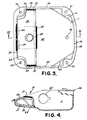
- the chair control generally indicated by the numeral 10 comprises an open top, generally rectangular, drawn cup 11 for housing an energy storage package generally indicated by the numeral 12.
- Means for securing a base structure to the cup 11 and evenly distributing stress to the walls of the cup 11 is disposed at 14.
- First and second stretchers 15 and 16 respectively, are disposed on opposite sides of the cup 11.
- the stretchers 15 and 16 enable the chair control to be secured to a tilting chair member.
- An axle 20 is secured to and extends between the stretchers 15 and 16, the axle being journalled in the drawn cup 11.
- the present embodiment of the invention is particularly adapted for use as a tilting chair control.
- a tilting chair the seat and back are firmly fastened together and the chair is mounted on a base providing pivotable movement.
- the chair control 10 is disposed between the base and the chair, providing backward movement and effectively spring biasing the chair in a generally upright position.
- the means 14 for securing the base to the cup 11 and evenly distributing stress to the walls of the cup includes apertures 21 and 22 for receiving the spindle of a base structure.
- the stretchers such as the one illustrated at 16 are bolted or otherwise secured in a suitable manner to the underside of the chair seat. The tilting action of the chair results from rotation of the axle 20 journalled in the drawn cup 11.
- a chair control constructed in accordance with the present invention may be employed with a chair having stationary and tilting chair sections.
- An example of such a chair is a secretarial chair having a chair back which is mounted for backward tilting movement relative to the seat.
- the seat is fixed and forms part of the base structure and the seat back is held in a normal or upright position by the chair control 10.
- the chair control 10 When applying the chair control 10 to a secretarial chair or the tike, the rectangular drawn cup 11 is secured to the chair seat by a bolt or the like inserted through the apertures 21 and 22.
- the tilting chair back is then secured to the stretchers 15 and 16 to allow tilting movement of the chair back through the angle ⁇ .
- the energy package contained in the drawn cup 11 serves to spring bias the stretchers and hence the chair back to a generally upright position.
- first and second interlocking spindle support members 30 and 31 which form a cup reinforcing and stress distributing structure roughly box-shaped in cross section.
- the box-shaped cup reinforcing structure is welded to opposing sides 32 and 33 of the cup 11 and to a third side 34 opposite the side 36 and the bottom 35 of the cup 11.
- the box-shaped structure is in itself inherently stiff and by virtue of its widely distributed four point contact with the cup 11, serves to evenly distribute stresses from the spindle to the relatively thin drawn cup 11.
- the interfitting spindle support members 30 and 31 include mating tabs and slots at 38, 39 and 40, defining an interface between the support members disposed so that the support members 30 and 31 may be fused together and to the cup 11 with single welds disposed at 41 and 42.
- the interlocking spindle support members 30 and 31 may then be dropped over the spindle and secured there by gravity while welds 41 and 42 are applied.
- Welds at 43 and 44 secure the box-shaped reinforcing structure to opposing sides 32 and 33, respectively, of the drawn cup 11.
- Another advantage provided by the drawn cup is that the drawn cup can be easily manufactured with a greater accuracy in dimensions than folded structures.
- the drawn cup 11 further includes means for journalling a tilting chair member about the cup, the means comprising a pair of apertures 45 and 46 disposed in opposing sides 32 and 33, respectively, of the drawn cup 11.
- the apertures 45 and 46 receive the relatively large diameter axle 20 (best illustrated in Figure 1) which contributes to the feasibility of the drawn cup design by serving to evenly distribute stresses transmitted to the cup from the tilting chair member.
- the diameter of the axle 20 is approximately 2.5 cms, or larger.
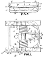
- the cup 11 further includes stop means disposed on the top four corners of the cup in apertures 50, 51, 52 and 53 (best illustrated in Figure 3) for defining the arc of travel.
- the stop means fitted into these apertures comprises a plurality of plastic buttons 54 best illustrated in Figures 1 and 2.
- the buttons 54 are formed of a urethane elastomer and include a centrally located projection 55.
- the buttons 54 prevent metal-to-metal contact between the stretchers 15 and 16 and the cup 11.
- the projections 55 provide a further cushioning effect to provide a stop action which is initially soft but quickly firms.
- the buttons 54 are mounted on a flange 56 which extends about the periphery of the cup.
- the flange 56 serves additionally to strengthen the cup and aids in tooling considerations.
- the four top corners of the cup in which the apertures 50-53 are provided are further strengthened by indented sidewall portions 60, 61, 62 and 63 which each interconnect two sides of the cup below each of the top four corners of the cup.
- the indented sidewall portion 60 disposed below the aperture 50 interconnects the sidewalls 33 and 34 of the cup 11.
- the axle 20 is journalled in the drawn cup 11 with plastic bearing inserts such as the one illustrated at 70.
- the plastic bearing inserts are simply pressed into the cup 11 and mainly receive radial loading from the axle 20.
- the bearing inserts 70 also include thrust bearing faces 71 that face away from the cup 11 to maintain appropriate spacing between the cup 11 and the stretchers 15 and 16. Spacing between the cup 11 and the stretchers 15 and 16 sufficient to ensure clearance for the flange 56 extending about the periphery of the cup is ensured by inwardly projecting embossed sections 72 on the stretchers 15 and 16.
- the inwardly embossed sections 72 are disposed on the stretchers 15 and 16 at the point at which they are secured to the axle 20, such that the thrust bearing faces 71 of the bearings 70 ride thereagainst.
- the embossed sections 72 reduce the thickness required for the bearing inserts 70 and thus reduce the cost of the inserts.
- the ends of the axle 20 are slotted as illustrated at 74 and the stretchers 15 and 16 are provided with webbed openings 75 through which the ends of the axle project.
- Each webbed opening 75 includes a web 76 which is aligned with the slot 74 provided on the respective end of axle 20.
- the axle 20 is conveniently secured to the stretchers 15 and 16 by swaging or expanding the ends of the axle as illustrated at 77.
- the swaged ends 77 of the axle 20 are surrounded by inwardly embossed section 72 of stretchers 15 and 16, and this serves conveniently to reduce the possibility of snagging fabric or scratching the occupant of the chair.
- the energy package 12 may be characterized as being of the torsion coil spring type although it should be understood that with minor modifications other types of energy packages may be employed.
- known types of energy packages that may be used with the present invention include rubber pack, coil spring, leaf spring, and torsion bar systems for storing energy.
- Rubber packs comprise a stationary support member and a tilting member interconnected by a web of resilient rubber.
- Coil spring systems may be of the torsion spring type or simple compression and tension type.
- Torsion coil springs may have the coil fixed with one or two tails of the coil deflected, or both tails of the coil may be fixed and the coil itself may be deflected.
- Leaf spring systems include cantilever and beam loaded energy storing members.
- Torsion bar systems may be fixed at one end with a moment applied to the opposite end or may be fixed at both ends with a moment applied to the centre of the torsion bar.
- Coil spring 80 includes tails 82 and 83 and coil spring 81 includes tails 84 and 85.
- the coil springs 80 and 81 are carried by the axle 20 which fixes the position of the coils in the drawn cup 11 and prevents eccentric deflection of the coil springs when torsionally loaded.
- a protective plastic sleeve 86 is disposed between the axle 20 and the springs 80 and 81. The plastic sleeve 86 prevents metal to metal contact between the springs and the axle, improving the feel and sound of the chair control as well as lengthening the life of the springs.
- Tails 82 and 84 of the coil springs 80 and 81 rest under the stretchers 15 and 16, respectively, and are provided with a sufficient torsional preload to urge the stretchers 15 and 16 to the generally horizontal position illustrated by the stretcher 16 in Figure 2.
- the stretchers 15 and 16 include spring locators 87 formed integrally with the stretchers at a significant manufacturing and cost advantage.
- the spring locators 87 are stamped, punched or otherwise suitably formed in the stretchers and the spring tails 82 and 84 are retained therebetween in the area generally indicated at 87'.
- the tails 83 and 85 on the opposite ends of the coils 80 and 81 respectively, are caught by means for adjusting the preload of the coils 80 and 81, generally indicated at 88.
- the means for adjusting the preload of the energy package comprises a bracket 89, including notches 90 and 91 through which the tails 83 and 85 of the coil springs 80 and 81 project, resting under the bracket 89.
- the bracket 89 is vertically adjustable to vary the preload of the springs 80 and 81.
- the bracket 89 includes a flange 92 which slides along a vertical wall 93 of the drawn cup 11 to guide vertical movement of the bracket 89.
- a threaded adjustment rod or bolt 94 (best illustrated in Figure 8) engages a threaded aperture 95 in the bracket 89.
- the bottom of the drawn cup 11 includes an aperture 96 best illustrated in Figure 3.
- the threaded adjustment rod includes a handle 97 including a first circumferential shoulder 98.
- the threaded adjustment rod 94 is inserted through the aperture 96 in the drawn cup 11 and threadably engages the bracket 89 to vertically adjust the bracket 89 within the drawn cup 11 by rotation of the handle 97.
- a retaining screw 99 is threadably received in an axially extending aperture 99' disposed on the end of the adjustment rod 94. The retaining screw 99 prevents the bracket 89 from becoming separated from the adjustment rod 94 at the minimum preload adjustment.
- Provision of dual coil springs 80 and 81 in combination with the means for adjusting the preload of the coil springs generally indicated at 88 provides an added safety factor in the case of energy package failure. For example, if one of the two coil springs 80 and 81 were to fail, the bracket 89, although eccentrically loaded would still be sufficiently supported by the threaded adjustment rod 94 and guided by the rearwall 93 to ensure that the tail of the remaining coil spring would remain under the bracket 89, preventing a complete energy package failure.
- the handle 97 and first circumferential shoulder 98 of the threaded adjustment rod 94 are made of plastic, or the like, cast on the threaded rod 94. This is the conventional manner of constructing threaded adjustment rods.
- the first circumferential shoulder 98 disintegrates, releasing the adjustment rod and causing a total energy package failure. In the prior art, this provides a potentially dangerous situation, since upon energy package failure, the chair will free-fall through the angle a, against its rear stops. Since the angle a is normally about 18 or 20 degrees, often this free-fall is sufficient to overturn the chair and endanger the occupant.
- the threaded rod 94 includes means for reducing the likelihood of energy package failure comprising a second circumferential shoulder 100 disposed on the threaded rod 94.
- the second circumferential shoulder 100 is formed from the base metal of the threaded adjustment rod 94 and is disposed on the adjustment rod outside the drawn cup 11 and the first circumferential shoulder 98.
- the second circumferential shoulder 100 acts as a backup, preventing release of the threaded adjustment rod 94.
- the second shoulder 100 allows the use of a simple moulded or cast plastic first shoulder and handle, decreasing the cost of the chair control and yet substantially reducing the probability of an energy package failure that could endanger the occupant upon failure of the plastic handle and first shoulder.
Landscapes
- Chairs Characterized By Structure (AREA)
- Purses, Travelling Bags, Baskets, Or Suitcases (AREA)
- Chair Legs, Seat Parts, And Backrests (AREA)
Claims (18)
und mit einem schwenkbaren Rahmenteil mit einem ersten und einem zweiten Längsträger (15, 16), die jeweils an dem schwenkbaren Teil des Stuhles befestigbar sind, wobei das schwenkbare Rahmenteil durch ein Energiespeicherelement (12) in Richtung einer vorbestimmten relativen Lage des feststehenden und des schwenkbaren Rahmenteiles federnd vorgespannt ist, dadurch gekennzeichnet, daß das feststehende Rahmenteil von einer an seiner Oberseite offenen, tiefgezogenen Wanne (11) mit vier Seitenwänden (32, 33, 34, 36) und einem im wesentlichen rechteckigen Boden (35) gebildet ist und das Energiespeicherelement (12) aufnimmt, und daß die Befestigungsvorrichtung (14), welche die Kräfte in die Seitenwände und den Boden der Wanne einleitet, eine erste (30) und zweite (31) Spindellagereinrichtung aufweist, die zusammen ein in etwa kastenförmiges Wannen-Versteifungselement bilden, das an den Boden (35) und die drei angrenzenden Seitenwände (32, 33, 34) der Wanne (11) angeschweißt ist.
Applications Claiming Priority (2)
| Application Number | Priority Date | Filing Date | Title |
|---|---|---|---|
| US957748 | 1978-11-06 | ||
| US05/957,748 US4214726A (en) | 1978-11-06 | 1978-11-06 | Chair control |
Publications (2)
| Publication Number | Publication Date |
|---|---|
| EP0010990A1 EP0010990A1 (de) | 1980-05-14 |
| EP0010990B1 true EP0010990B1 (de) | 1983-06-08 |
Family
ID=25500081
Family Applications (1)
| Application Number | Title | Priority Date | Filing Date |
|---|---|---|---|
| EP79302477A Expired EP0010990B1 (de) | 1978-11-06 | 1979-11-06 | Reguliereinrichtungen für Stühle |
Country Status (6)
| Country | Link |
|---|---|
| US (1) | US4214726A (de) |
| EP (1) | EP0010990B1 (de) |
| JP (1) | JPS5566320A (de) |
| AU (1) | AU524576B2 (de) |
| CA (1) | CA1121709A (de) |
| DE (1) | DE2965634D1 (de) |
Families Citing this family (12)
| Publication number | Priority date | Publication date | Assignee | Title |
|---|---|---|---|---|
| CA1109386A (en) * | 1978-03-29 | 1981-09-22 | Eddie A.J. Large | Resilient mounting for a reclining seat |
| US4314728A (en) * | 1980-05-01 | 1982-02-09 | Steelcase Inc. | Chair control |
| CA1162834A (en) * | 1980-05-01 | 1984-02-28 | Ronald L. Whitwam | Chair control tension adjustment assembly |
| US4479679A (en) * | 1981-06-08 | 1984-10-30 | Steelcase Inc. | Body weight chair control |
| US5567012A (en) * | 1986-04-10 | 1996-10-22 | Steelcase, Inc. | Chair control |
| US4736984A (en) * | 1986-10-31 | 1988-04-12 | Super Sagless Corporation | Pivot assembly for reclining chair with rocking feature |
| US4892354A (en) * | 1989-06-30 | 1990-01-09 | Shepherd Products U.S., Inc. | Chair seat tilt control |
| US5222781A (en) * | 1992-01-13 | 1993-06-29 | Mele Peter C | Automatically adjustable bicycle seat apparatus |
| CH690019A5 (de) * | 1992-07-16 | 2000-03-31 | Giroflex Entwicklungs Ag | Traggestell für einen Stuhl, insbesondere für einen in der Höhe und Neigung verstellbaren Bürostuhl. |
| US5782536A (en) * | 1995-02-17 | 1998-07-21 | Steelcase Inc. | Modular chair construction and method of assembly |
| US5810439A (en) * | 1996-05-09 | 1998-09-22 | Haworth, Inc. | Forward-rearward tilt control for chair |
| US6585320B2 (en) | 2001-06-15 | 2003-07-01 | Virco Mgmt. Corporation | Tilt control mechanism for a tilt back chair |
Family Cites Families (13)
| Publication number | Priority date | Publication date | Assignee | Title |
|---|---|---|---|---|
| US623008A (en) * | 1899-04-11 | Automatic stool | ||
| US1570436A (en) * | 1924-04-07 | 1926-01-19 | Robert K Dawson | Chair base |
| US1986105A (en) * | 1932-04-22 | 1935-01-01 | Thomas W Foote | Swivel chair |
| US2818911A (en) * | 1954-11-05 | 1958-01-07 | Trumbull Dev Corp | Tiltable office chair |
| US2845991A (en) * | 1955-04-28 | 1958-08-05 | Manton Ahlberg H | Chair control or iron |
| US3185429A (en) * | 1963-05-15 | 1965-05-25 | Seng Co | Tilting chair mechanism |
| US3339973A (en) * | 1966-01-05 | 1967-09-05 | Doerner Products Co Ltd | Torsion spring chair control |
| US3693495A (en) * | 1970-10-30 | 1972-09-26 | David P Wagner | Composite screw |
| GB1343305A (en) * | 1971-04-01 | 1974-01-10 | Werner P G | Adjustable resiliently hinged device for chairs and the like |
| US3758157A (en) * | 1971-09-20 | 1973-09-11 | Steelcase Inc | Chair |
| US3813073A (en) * | 1972-04-21 | 1974-05-28 | Steelcase Inc | Dual torsion bar chair control |
| US3863982A (en) * | 1973-02-05 | 1975-02-04 | Est Company Inc | Tilt-swivel mechanism for a chair |
| US4077596A (en) * | 1975-06-18 | 1978-03-07 | Bliss & Laughlin Industries, Incorporated | Low silhouette chair tilting control assembly |
-
1978
- 1978-11-06 US US05/957,748 patent/US4214726A/en not_active Expired - Lifetime
-
1979
- 1979-10-15 CA CA000337588A patent/CA1121709A/en not_active Expired
- 1979-10-19 AU AU51971/79A patent/AU524576B2/en not_active Ceased
- 1979-11-01 JP JP14195979A patent/JPS5566320A/ja active Granted
- 1979-11-06 EP EP79302477A patent/EP0010990B1/de not_active Expired
- 1979-11-06 DE DE7979302477T patent/DE2965634D1/de not_active Expired
Also Published As
| Publication number | Publication date |
|---|---|
| AU5197179A (en) | 1980-05-15 |
| JPH0236244B2 (de) | 1990-08-16 |
| JPS5566320A (en) | 1980-05-19 |
| AU524576B2 (en) | 1982-09-23 |
| US4214726A (en) | 1980-07-29 |
| EP0010990A1 (de) | 1980-05-14 |
| CA1121709A (en) | 1982-04-13 |
| DE2965634D1 (en) | 1983-07-14 |
Similar Documents
| Publication | Publication Date | Title |
|---|---|---|
| EP0010990B1 (de) | Reguliereinrichtungen für Stühle | |
| EP0621145B1 (de) | Befestigungsbügel | |
| JP3321727B2 (ja) | 椅子の座の回動機構 | |
| GB2453687A (en) | New front-end frame concept for the body structure on a multiple-platform | |
| US5165756A (en) | Tubular seat back frame with U-shaped closed section reinforcement weld plate | |
| US7621431B2 (en) | Folding stroller tray | |
| US6318750B1 (en) | Shock absorbing device for a stroller | |
| KR100287443B1 (ko) | 탄성체 압축 스프링 | |
| US11247586B2 (en) | Seat support frame of a motor vehicle seat comprising a seat frame and an inclination-adjustable seat shell | |
| JP5078390B2 (ja) | 椅子 | |
| JPH10100907A (ja) | エアバッグ装置付きステアリングホイール | |
| JP3587037B2 (ja) | 車椅子のアームレスト装置 | |
| JP2000052903A (ja) | エアバッグ装置付きステアリングホイ―ル | |
| JP5260181B2 (ja) | 座跳ね上げ式椅子 | |
| US2061271A (en) | Scale | |
| JP2024015647A (ja) | ランドセル | |
| JP7650143B2 (ja) | 折り畳み式椅子 | |
| JP7725325B2 (ja) | 椅子 | |
| JP2641804B2 (ja) | 椅 子 | |
| KR200168923Y1 (ko) | 등받이 절첩구조를 가진 오토바이용 짐받이 | |
| JP2786778B2 (ja) | 椅 子 | |
| JPH0732318Y2 (ja) | 衝撃エネルギー吸収ステアリングホイール | |
| JP2004058716A (ja) | 衝撃吸収式ステアリングコラム装置 | |
| JP4255868B2 (ja) | 椅子 | |
| JP4629266B2 (ja) | 椅子における背凭れ構造 |
Legal Events
| Date | Code | Title | Description |
|---|---|---|---|
| PUAI | Public reference made under article 153(3) epc to a published international application that has entered the european phase |
Free format text: ORIGINAL CODE: 0009012 |
|
| AK | Designated contracting states |
Designated state(s): DE FR GB IT |
|
| 17P | Request for examination filed | ||
| ITF | It: translation for a ep patent filed | ||
| GRAA | (expected) grant |
Free format text: ORIGINAL CODE: 0009210 |
|
| AK | Designated contracting states |
Designated state(s): DE FR GB IT |
|
| REF | Corresponds to: |
Ref document number: 2965634 Country of ref document: DE Date of ref document: 19830714 |
|
| ET | Fr: translation filed | ||
| PLBE | No opposition filed within time limit |
Free format text: ORIGINAL CODE: 0009261 |
|
| STAA | Information on the status of an ep patent application or granted ep patent |
Free format text: STATUS: NO OPPOSITION FILED WITHIN TIME LIMIT |
|
| 26N | No opposition filed | ||
| GBC | Gb: translation of claims filed (gb section 78(7)/1977) | ||
| ITTA | It: last paid annual fee | ||
| PGFP | Annual fee paid to national office [announced via postgrant information from national office to epo] |
Ref country code: GB Payment date: 19931011 Year of fee payment: 15 |
|
| PGFP | Annual fee paid to national office [announced via postgrant information from national office to epo] |
Ref country code: FR Payment date: 19931110 Year of fee payment: 15 |
|
| PGFP | Annual fee paid to national office [announced via postgrant information from national office to epo] |
Ref country code: DE Payment date: 19931126 Year of fee payment: 15 |
|
| PG25 | Lapsed in a contracting state [announced via postgrant information from national office to epo] |
Ref country code: GB Effective date: 19941106 |
|
| GBPC | Gb: european patent ceased through non-payment of renewal fee |
Effective date: 19941106 |
|
| PG25 | Lapsed in a contracting state [announced via postgrant information from national office to epo] |
Ref country code: FR Effective date: 19950731 |
|
| PG25 | Lapsed in a contracting state [announced via postgrant information from national office to epo] |
Ref country code: DE Effective date: 19950801 |
|
| REG | Reference to a national code |
Ref country code: FR Ref legal event code: ST |