EP0010778B2 - Dispositif d'empilage - Google Patents
Dispositif d'empilage Download PDFInfo
- Publication number
- EP0010778B2 EP0010778B2 EP19790104349 EP79104349A EP0010778B2 EP 0010778 B2 EP0010778 B2 EP 0010778B2 EP 19790104349 EP19790104349 EP 19790104349 EP 79104349 A EP79104349 A EP 79104349A EP 0010778 B2 EP0010778 B2 EP 0010778B2
- Authority
- EP
- European Patent Office
- Prior art keywords
- location
- transport platen
- stack
- light
- pairs
- Prior art date
- Legal status (The legal status is an assumption and is not a legal conclusion. Google has not performed a legal analysis and makes no representation as to the accuracy of the status listed.)
- Expired - Lifetime
Links
Images
Classifications
-
- B—PERFORMING OPERATIONS; TRANSPORTING
- B65—CONVEYING; PACKING; STORING; HANDLING THIN OR FILAMENTARY MATERIAL
- B65G—TRANSPORT OR STORAGE DEVICES, e.g. CONVEYORS FOR LOADING OR TIPPING, SHOP CONVEYOR SYSTEMS OR PNEUMATIC TUBE CONVEYORS
- B65G57/00—Stacking of articles
- B65G57/02—Stacking of articles by adding to the top of the stack
- B65G57/16—Stacking of articles of particular shape
- B65G57/20—Stacking of articles of particular shape three-dimensional [3D], e.g. cubiform or cylindrical
- B65G57/22—Stacking of articles of particular shape three-dimensional [3D], e.g. cubiform or cylindrical in layers each of predetermined arrangement
- B65G57/24—Stacking of articles of particular shape three-dimensional [3D], e.g. cubiform or cylindrical in layers each of predetermined arrangement the layers being transferred as a whole, e.g. on pallets
- B65G57/245—Stacking of articles of particular shape three-dimensional [3D], e.g. cubiform or cylindrical in layers each of predetermined arrangement the layers being transferred as a whole, e.g. on pallets with a stepwise downward movement of the stack
Definitions
- the invention relates to a stacking device with a transport plate for conveying the piece goods received at a first location and arranged in one position, further with means for automatically aligning the transport plate at a predetermined height and with means for moving the transport plate over a second location and for depositing the layer mentioned there as part of a stack formed from a plurality of layers, light control units being provided for automatically aligning the transport plate with respect to the stack height to be taken in the second position, depending on the stack that may already be present in the second position.
- Such a stacking device is known from DE-A-2 005 446.
- piece goods picked up by the transport plate are each brought into such a high position that subsequent storage on an already existing stack is possible, the necessary height position being determined automatically regardless of the respective height of the piece goods and thus the stack.
- This is done by means of light projectors, which throw a light beam diagonally to the stack to a photosensitive receiver.
- the light projector and associated receiver are therefore arranged separately from one another.
- the object of the invention is to improve the known device with regard to the arrangement of the light control units.
- the light control units each form pairs of light control units arranged one above the other, designed as a light source and receiving element, and two pairs are arranged side by side in such a way that, in cooperation with reflectors, the stack height at the second point either covers or releases both pairs or only the lower one Pair covers, so that when the cover is released or released, the transport plate is moved vertically and is held in place only when the lower pair is covered.
- a stripper can be assigned to the transport plate which can be moved transversely to the transport plate. The stripper thus takes over the exact alignment of the piece goods combined into one layer at the first position.
- the scraper can consist of an inner and outer plank that cross the transport plate.
- the scraper is expediently arranged so that it can be moved in the direction of movement of the transport plate.
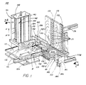
- FIG. 1 shows a stacking device 100 according to the invention arranged in the vicinity of a conveyor device 300 at a loading point P2.
- a transport plate 110 is slidably supported by a carriage 101. The latter is fastened in a self-supporting manner and can be moved in the vertical upward direction, as indicated by the arrow A ′, and in the vertical downward direction, as indicated by the arrow A ′′, along guide rails (not shown) of a stack carrier 140.
- the stack carrier 140 itself has side parts 141 and 142 and an end part 143.
- a screw spindle 144 is rotatably fastened in the end part 143 and in an opposite bottom part, not visible in FIG. 1, a screw spindle 144 is rotatably fastened.
- the screw spindle 144 is driven in the usual way clockwise or counterclockwise, for example by a motor, not shown, which is fastened to one of the side parts 143 or 142 and is operatively connected to a drive gear 146 of the screw spindle via a chain 148 or a belt.
- the screw spindle 144 is also screwed into a shoulder of the carriage 101, which is not visible in FIG. 1, so that when it rotates clockwise or counterclockwise, this carriage is moved upwards or downwards in the direction of the arrows A 'or A ".
- the carriage 101 also carries a scraper 150, which consists of an inner plank 151 and outer planks 151-1 and 152-2. As will be explained, the outer planks are laterally movable with respect to the inner plank 151 at fixed intervals of the stacking cycle. Both the inner plank 151 and the outer planks 151-1 and 152-2 are attached to carriage 101 in the manner discussed below, but are only an example of an attachment.
- the stacking device 100 according to FIG. 1 has a rearward, adjustable position template template plank 153, which is also used to form the position B 'shown in broken lines on the transport plate 110.
- automatic light control is used.
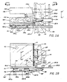
- light control elements 102 and 103 are attached to carriage 101 in the manner shown in FIG. 2A.
- the light control elements cooperate with a stop piece 170, which has a plurality of reflectors 171, which are arranged in two vertical columns 172 and 173.
- the column 172 is located in the center of the stop piece and comprises a double row of reflectors 171.
- the column 173 is arranged on the edge of the stop piece and has a single row of reflectors 171. The reason why a double row of reflectors is used in the middle column 172 is explained in more detail below.
- the stop piece 170 is adjustable both with respect to the surface of the conveyor device 300 at the pattern formation point and with respect to the stacking device 100.
- the stacking device 100 is controlled from a control box 180.
- a hand crank 104 is used to bring the rear pattern template plank 153 into the desired position with respect to the inner plank 151 of the stripper 150.
- the edge of the pattern template plank 153 may be spaced a predetermined distance from the surface of the transport plate 110.
- a pattern depth switch 105 ' is then expediently set with respect to the rear of an assumed position B'.
- the depth D of the position B ' is then measured, whereupon the spatial position of the stop piece 170 is adjusted using the scale 174 together with a conventional rack drive, not shown.
- a control lever 181 is attached to the control box 180 and is used to trigger certain functions by hand. Lifting the control lever 181 causes the carriage 101 to move in the direction A '. Lowering the lever 181, on the other hand, causes the carriage 101 to move downward in the direction of the arrow A ". When the lever 181 is moved horizontally in one direction, the scraper 150 moves apart, as shown in FIG. 2B. The horizontal movement of the Lever 181 in the other direction, on the other hand, leads to the carriage 101 returning to its starting position, which is located at a predetermined location at the level of the operator.
- the control box 180 also includes a selector switch 182, in one position of which the automatic or normal operation takes place and in the other position the stripper is raised as shown in Fig. 2A.
- a further component of the control box 180 is a speed selector 183, with the aid of which the speed of the movement of the transport plate 110 can be adjusted during its outward stroke indicated by the arrow C '.
- the reverse stroke according to the arrow C is automatically kept at a maximum value under all circumstances. This allows the outward stroke to be set for a large number of position patterns.
- Further components of the control box 180 are a start button 184 which is used to start the drive machine, and a stop button 185. Another button 186 is used to define a cyclical repetition of the layer arrangement of the stacks.
- FIGS. 2A to 2C show that the stripper 150 is connected to a projecting element 154, which in turn is fastened to bearings 155A and 155B, which comprise vertical slide rods 156A and 156B.
- the protruding element 154 allows the entire stripper 150 to be moved up and down along the slide rods 156A and 156B according to the arrows U 'and U ", this movement being caused by a control cylinder 157.
- the end of the control cylinder 157 is middle a movable rod 157R is connected to the slide 101, so that when the control cylinder 157 is actuated in the usual way (fluid pressure influencing an internally movable piston) the entire wiper moves up or down in the direction of the arrows U 'or U ".
- the upward movement of the scraper 150 leads to the fact that it also moves in the transverse direction to the transport plate 110 into the position 150 'shown in dashed lines.
- each of the light control units 102L, 102V and 103L, 103V consists of a light source and a receiving element which reacts to light emanating from the light source and reflected by one of the reflectors 171 according to FIG. 1.
- FIG. 2B shows a top view of the arrangement shown schematically in FIG. 2A. It can be seen from this that the transport plate 110 can be moved with the aid of a toothed rack 111 and a pinion 112. The pinion is driven via a gear 113 by a motor 114 which is attached to the slide 101. 2B shows the outer and inner planks 152 and 151 of the scraper 150 and the manner in which the outer planks 152-1 and 152-2 relate to the inner plank 151 using a second piston-cylinder assembly 158 are pivotable.
- the next step in the stacking cycle is to lower the stripper 150 due to the opposite operation of the control cylinder 157.
- the upper outer plank 152-1 then engages the lower outer plank 152-2 (shown in phantom) by inserting a pin 150p into a recess 150k of the lower outer plank 152-2 engages.
- the two outer planks 152-1 and 152-2 are then pivoted outward into position 152 'under the action of cylinder 158 to effect the desired alignment of the stack.
- the lower outer plank 152-2 is rotatably connected to the carriage via arms 106 as shown in FIG. 1.
- the lower outer plank has openings 152a for the light from the light control units.
- the transport plate 110 is moved back in the direction of arrow C "due to the reverse mode of operation of the motor 114.
- the correct distance between the position deposited on the stack and the edge of the stack is shown by the movement of the cylinder 158 according to FIG. 2B in the broken line
- the upper outer plank is connected to lugs 151A and 151B by means of pivotable link members 152A and 152B
- the rod 158R is connected to the articulated member 152B and, when actuated, brings it into the position 152'B shown in dashed lines. From FIG. 2B one can also see an extension 120 of the carriage 101 which has a threaded bore 130 for the Screw spindle 144 according to FIG. 1 has.
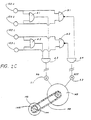
- the automatic alignment of the slide 101 in the desired stack height takes place due to the interaction of the pairs of light control units 102L, 102V and 103L, 103V with the electrical circuit shown in FIG. 2C.
- the upper light control units 102U and 103U are connected to the input terminals of an AND gate A1 and a NAND gate N1.
- the outputs of the AND gates A1 and A2 are connected to the inputs of a third AND gate A3.
- the outputs of the NAND gates N1 and N2, however, are connected to the inputs of a fourth AND gate A4.
- the downward movement of the carriage 101 is controlled by the output signal of the AND gate A3 via a switch S1.
- the upward movement of the carriage is controlled by the output signal of the AND gate A4 via a switch S2.
- the AND gates A1, A2 and A3 are active, whereas the AND gate A4 is inactive, so that a signal is generated that causes the carriage to move downward when switch S1 is closed. This movement continues until one of the receiving organs no longer receives light. It will be one of the lower receiving elements, since such one first encounters darkened conditions, which are caused, for example, by hitting the upper edge of the stack which has been formed at the stacking point P2 or by being on one hits the lower stop. In the latter case, the carriage can be caused to search for a starting position which is at a predetermined operating level by switching to an upward movement which is ended when, for example, a magnetically acting shut-off device on the stack carrier responds.
- the carriage remains in the position in which this constellation occurs because at least one of the AND elements A1 or A2 is inactive, as a result of which the AND gate A3 on the output side also becomes inactive.
- the carriage 101 therefore moves upward when the switch S2 is closed. This movement continues until two receiving elements located on the same level receive reflected light. These will be the upper receiving elements 102U and 103U, since they are the first to be affected by the reflected light, which is caused, for example, by passing through the upper edge of the stack formed at the stacking point P2 or by pointing to an upper one Bump limiting element. In the latter case, the carriage can be made to search for a starting position again.
- NAND gates N1 and N2 to control the upward movement, if only one of the upper receiving elements 102U or 103U receives light, the upward movement continues until both receiving elements receive reflected light. This will put the transport into operation plate is prevented until it is in a position in which a separation from the previously deposited position has taken place, regardless of whether it is crooked or otherwise not properly aligned.
- a DC motor is preferably used to achieve precise speed control of the transport plate 110.
- the motor causing the upward and downward movement i.e. motor 149 in Fig. 2C
- the motor causing the upward and downward movement is preferably a DC motor with conical brakes. When it is connected to the operating voltage, it swings out to the side; when it is switched off, it slides into its braked starting position.
- the scraper 150 is preferably actuated by the two fluid-controlled cylinders 157 and 158, in which the fluid is, for example, air.
- other fluid means such as e.g. Oil, it is also possible to replace the DC motor with an equivalent drive.
- the receiving members 103U and 103L are preferably fastened in such a way that they receive light beams diagonally reflected by the double row 172 of reflectors 171. This ensures proper operation even if the layer of a stack located on the transport plate has a gap between its individual components, through which the light could pass unhindered and could thus cause the transport plate to look for the wrong level. Because of the diagonal arrangement of the receiving members 103U and 103L, double reflectors are required at every height of the double row 172, so that a proper operation is ensured regardless of the setting of the stop piece 170. The outer reflectors of the double row 172 are then active when the stop piece is set at a distance from the slide, while the inner reflectors are active when the stop piece is set in the direction of the slide.
Landscapes
- Engineering & Computer Science (AREA)
- Mechanical Engineering (AREA)
- Pile Receivers (AREA)
- Stacking Of Articles And Auxiliary Devices (AREA)
Claims (5)
Applications Claiming Priority (2)
| Application Number | Priority Date | Filing Date | Title |
|---|---|---|---|
| US95775878A | 1978-11-06 | 1978-11-06 | |
| US957758 | 1978-11-06 |
Publications (4)
| Publication Number | Publication Date |
|---|---|
| EP0010778A2 EP0010778A2 (fr) | 1980-05-14 |
| EP0010778A3 EP0010778A3 (fr) | 1980-09-03 |
| EP0010778B1 EP0010778B1 (fr) | 1983-11-09 |
| EP0010778B2 true EP0010778B2 (fr) | 1990-11-07 |
Family
ID=25500090
Family Applications (1)
| Application Number | Title | Priority Date | Filing Date |
|---|---|---|---|
| EP19790104349 Expired - Lifetime EP0010778B2 (fr) | 1978-11-06 | 1979-11-06 | Dispositif d'empilage |
Country Status (4)
| Country | Link |
|---|---|
| EP (1) | EP0010778B2 (fr) |
| JP (1) | JPS55123821A (fr) |
| AU (1) | AU535078B2 (fr) |
| DE (2) | DE2944556A1 (fr) |
Families Citing this family (1)
| Publication number | Priority date | Publication date | Assignee | Title |
|---|---|---|---|---|
| CN102502268B (zh) * | 2011-10-19 | 2013-12-18 | 中国建材国际工程集团有限公司 | 一种有关机械手玻璃堆垛系统第一片玻璃的定位方法 |
Family Cites Families (3)
| Publication number | Priority date | Publication date | Assignee | Title |
|---|---|---|---|---|
| SE322731B (fr) * | 1969-03-27 | 1970-04-13 | Weiner K | |
| DE2558233A1 (de) * | 1975-12-23 | 1977-07-07 | Herbert Kappenberg | Verfahren und vorrichtung zum stapeln von behaeltnissen |
| US4068765A (en) * | 1976-04-29 | 1978-01-17 | Vanguard Machinery Corporation | Stacking of materials |
-
1979
- 1979-10-22 AU AU52005/79A patent/AU535078B2/en not_active Ceased
- 1979-11-05 DE DE19792944556 patent/DE2944556A1/de not_active Withdrawn
- 1979-11-05 JP JP14215079A patent/JPS55123821A/ja active Pending
- 1979-11-06 EP EP19790104349 patent/EP0010778B2/fr not_active Expired - Lifetime
- 1979-11-06 DE DE7979104349T patent/DE2966393D1/de not_active Expired
Also Published As
| Publication number | Publication date |
|---|---|
| DE2966393D1 (en) | 1983-12-15 |
| DE2944556A1 (de) | 1980-05-14 |
| EP0010778A2 (fr) | 1980-05-14 |
| EP0010778B1 (fr) | 1983-11-09 |
| AU5200579A (en) | 1980-05-15 |
| JPS55123821A (en) | 1980-09-24 |
| AU535078B2 (en) | 1984-03-01 |
| EP0010778A3 (fr) | 1980-09-03 |
Similar Documents
| Publication | Publication Date | Title |
|---|---|---|
| EP4005955B1 (fr) | Machine pour trier et empiler les cagettes avec panneaux latéraux rabattables | |
| DE3613316C1 (de) | Vorrichtung zum Schneiden von gestapeltem,blattfoermigem Gut | |
| CH675574A5 (en) | Separating sheet inserter for pallet charging machine | |
| CH435098A (de) | Vorrichtung zum Gruppieren von mindestens angenähert quaderförmigen Gegenständen | |
| DE3217385A1 (de) | Verfahren zum entnehmen von wenigstens einem flachen gegenstand aus einem stapel und anwendung des verfahrens | |
| DE3430029C2 (de) | Einrichtung zum Beschicken von Buntaufteilsägemaschinen mit auf einem Hubtisch angeordneten tafel- bzw. plattenförmigen Werkstücken | |
| DE4125342C2 (de) | Positioniereinrichtung für Palettiermaschinen | |
| EP0010778B2 (fr) | Dispositif d'empilage | |
| DE69203382T2 (de) | Vorrichtung zur Herstellung oder Zusammensetzung von Holzpaletten. | |
| CH620883A5 (en) | Device for stacking drums provided with stacking grooves | |
| DE1556119C3 (de) | Verfahren und Vorrichtung zum Legen von Lagen zueinander paralleler Bretter mit vorgegebener wählbarer Lagengesamtbreite | |
| EP0822739B1 (fr) | Appareil automatisé de test de cartes de circuit électronique | |
| DE2905852A1 (de) | Verfahren und vorrichtung zur bildung von einem stapel aus einer bestimmten anzahl n packungen | |
| DE69829164T2 (de) | Verfahren und vorrichtung zum zuführen von platten zu einer plattensäge | |
| EP0020287A1 (fr) | Dispositif pour le désempilage de couches empilées | |
| EP0297201A1 (fr) | Dispositif d'amenée d'éléments longitudinaux coupés à une certaine longueur à une soudeuse de treillis | |
| AT384968B (de) | Vorrichtung zum zufuehren von abgelaengten laengselementen zum eingang einer gitterschweissmaschine | |
| DE4227508C2 (de) | Vorrichtung zum Schneiden von gestapelten Papierbögen, Pappen o. dgl. | |
| DE2852957A1 (de) | Vorrichtung zum selbsttaetigen stapeln von werkstuecken | |
| DE1536974A1 (de) | Verfahren zum Stapeln von kontinuierlich aufeinanderfolgend transportierten Drucklagen und Vorrichtung zu seiner Durchfuehrung | |
| DE1066478B (de) | Maschine zum Einbringen von Behaeltern in einen gemeinsamen Verpackungsbehaelter | |
| DE3227973A1 (de) | Verfahren und vorrichtung zum ausrichten der bogen eines stapels | |
| DE2631789C3 (de) | Fördervorrichtung für aus einer Spritzgießform ausgeworfene Spritzgu fiteile | |
| DE1532102C3 (de) | Maschine zum Stapeln von Zigaretten in vertikal bewegten Sammelbehältern | |
| DE2812518C2 (de) | Vorrichtung zum Vorkappen der Seitenware für eine Vollgatteranlage |
Legal Events
| Date | Code | Title | Description |
|---|---|---|---|
| PUAI | Public reference made under article 153(3) epc to a published international application that has entered the european phase |
Free format text: ORIGINAL CODE: 0009012 |
|
| AK | Designated contracting states |
Designated state(s): DE FR GB IT NL |
|
| PUAL | Search report despatched |
Free format text: ORIGINAL CODE: 0009013 |
|
| 17P | Request for examination filed |
Effective date: 19801104 |
|
| ITF | It: translation for a ep patent filed | ||
| GRAA | (expected) grant |
Free format text: ORIGINAL CODE: 0009210 |
|
| AK | Designated contracting states |
Designated state(s): DE FR GB IT NL |
|
| ET | Fr: translation filed | ||
| REF | Corresponds to: |
Ref document number: 2966393 Country of ref document: DE Date of ref document: 19831215 |
|
| PLBI | Opposition filed |
Free format text: ORIGINAL CODE: 0009260 |
|
| 26 | Opposition filed |
Opponent name: SEITZ ENZINGER NOLL MASCHINENBAU AG Effective date: 19840725 |
|
| PGFP | Annual fee paid to national office [announced via postgrant information from national office to epo] |
Ref country code: NL Payment date: 19891130 Year of fee payment: 11 |
|
| PUAH | Patent maintained in amended form |
Free format text: ORIGINAL CODE: 0009272 |
|
| STAA | Information on the status of an ep patent application or granted ep patent |
Free format text: STATUS: PATENT MAINTAINED AS AMENDED |
|
| 27A | Patent maintained in amended form |
Effective date: 19901107 |
|
| AK | Designated contracting states |
Kind code of ref document: B2 Designated state(s): DE FR GB IT NL |
|
| NLR2 | Nl: decision of opposition | ||
| EN3 | Fr: translation not filed ** decision concerning opposition | ||
| PG25 | Lapsed in a contracting state [announced via postgrant information from national office to epo] |
Ref country code: FR Effective date: 19910329 |
|
| PGFP | Annual fee paid to national office [announced via postgrant information from national office to epo] |
Ref country code: FR Payment date: 19910329 Year of fee payment: 12 |
|
| NLR3 | Nl: receipt of modified translations in the netherlands language after an opposition procedure | ||
| PG25 | Lapsed in a contracting state [announced via postgrant information from national office to epo] |
Ref country code: NL Effective date: 19910601 |
|
| NLV4 | Nl: lapsed or anulled due to non-payment of the annual fee | ||
| PGFP | Annual fee paid to national office [announced via postgrant information from national office to epo] |
Ref country code: GB Payment date: 19921222 Year of fee payment: 14 |
|
| PGFP | Annual fee paid to national office [announced via postgrant information from national office to epo] |
Ref country code: DE Payment date: 19930108 Year of fee payment: 13 |
|
| REG | Reference to a national code |
Ref country code: FR Ref legal event code: ST |
|
| PG25 | Lapsed in a contracting state [announced via postgrant information from national office to epo] |
Ref country code: GB Effective date: 19931106 |
|
| PG25 | Lapsed in a contracting state [announced via postgrant information from national office to epo] |
Ref country code: DE Effective date: 19940503 |
|
| GBPC | Gb: european patent ceased through non-payment of renewal fee |
Effective date: 19931106 |