EP0010778B2 - Piling arrangement - Google Patents
Piling arrangement Download PDFInfo
- Publication number
- EP0010778B2 EP0010778B2 EP19790104349 EP79104349A EP0010778B2 EP 0010778 B2 EP0010778 B2 EP 0010778B2 EP 19790104349 EP19790104349 EP 19790104349 EP 79104349 A EP79104349 A EP 79104349A EP 0010778 B2 EP0010778 B2 EP 0010778B2
- Authority
- EP
- European Patent Office
- Prior art keywords
- location
- transport platen
- stack
- light
- pairs
- Prior art date
- Legal status (The legal status is an assumption and is not a legal conclusion. Google has not performed a legal analysis and makes no representation as to the accuracy of the status listed.)
- Expired - Lifetime
Links
- 239000012530 fluid Substances 0.000 description 4
- 238000000151 deposition Methods 0.000 description 1
- 230000000694 effects Effects 0.000 description 1
- 230000003993 interaction Effects 0.000 description 1
- 210000000056 organ Anatomy 0.000 description 1
- 230000007261 regionalization Effects 0.000 description 1
- 238000000926 separation method Methods 0.000 description 1
Images
Classifications
-
- B—PERFORMING OPERATIONS; TRANSPORTING
- B65—CONVEYING; PACKING; STORING; HANDLING THIN OR FILAMENTARY MATERIAL
- B65G—TRANSPORT OR STORAGE DEVICES, e.g. CONVEYORS FOR LOADING OR TIPPING, SHOP CONVEYOR SYSTEMS OR PNEUMATIC TUBE CONVEYORS
- B65G57/00—Stacking of articles
- B65G57/02—Stacking of articles by adding to the top of the stack
- B65G57/16—Stacking of articles of particular shape
- B65G57/20—Stacking of articles of particular shape three-dimensional, e.g. cubiform, cylindrical
- B65G57/22—Stacking of articles of particular shape three-dimensional, e.g. cubiform, cylindrical in layers each of predetermined arrangement
- B65G57/24—Stacking of articles of particular shape three-dimensional, e.g. cubiform, cylindrical in layers each of predetermined arrangement the layers being transferred as a whole, e.g. on pallets
- B65G57/245—Stacking of articles of particular shape three-dimensional, e.g. cubiform, cylindrical in layers each of predetermined arrangement the layers being transferred as a whole, e.g. on pallets with a stepwise downward movement of the stack
Definitions
- the invention relates to a stacking device with a transport plate for conveying the piece goods received at a first location and arranged in one position, further with means for automatically aligning the transport plate at a predetermined height and with means for moving the transport plate over a second location and for depositing the layer mentioned there as part of a stack formed from a plurality of layers, light control units being provided for automatically aligning the transport plate with respect to the stack height to be taken in the second position, depending on the stack that may already be present in the second position.
- Such a stacking device is known from DE-A-2 005 446.
- piece goods picked up by the transport plate are each brought into such a high position that subsequent storage on an already existing stack is possible, the necessary height position being determined automatically regardless of the respective height of the piece goods and thus the stack.
- This is done by means of light projectors, which throw a light beam diagonally to the stack to a photosensitive receiver.
- the light projector and associated receiver are therefore arranged separately from one another.
- the object of the invention is to improve the known device with regard to the arrangement of the light control units.
- the light control units each form pairs of light control units arranged one above the other, designed as a light source and receiving element, and two pairs are arranged side by side in such a way that, in cooperation with reflectors, the stack height at the second point either covers or releases both pairs or only the lower one Pair covers, so that when the cover is released or released, the transport plate is moved vertically and is held in place only when the lower pair is covered.
- a stripper can be assigned to the transport plate which can be moved transversely to the transport plate. The stripper thus takes over the exact alignment of the piece goods combined into one layer at the first position.
- the scraper can consist of an inner and outer plank that cross the transport plate.
- the scraper is expediently arranged so that it can be moved in the direction of movement of the transport plate.
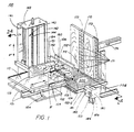
- FIG. 1 shows a stacking device 100 according to the invention arranged in the vicinity of a conveyor device 300 at a loading point P2.
- a transport plate 110 is slidably supported by a carriage 101. The latter is fastened in a self-supporting manner and can be moved in the vertical upward direction, as indicated by the arrow A ′, and in the vertical downward direction, as indicated by the arrow A ′′, along guide rails (not shown) of a stack carrier 140.
- the stack carrier 140 itself has side parts 141 and 142 and an end part 143.
- a screw spindle 144 is rotatably fastened in the end part 143 and in an opposite bottom part, not visible in FIG. 1, a screw spindle 144 is rotatably fastened.
- the screw spindle 144 is driven in the usual way clockwise or counterclockwise, for example by a motor, not shown, which is fastened to one of the side parts 143 or 142 and is operatively connected to a drive gear 146 of the screw spindle via a chain 148 or a belt.
- the screw spindle 144 is also screwed into a shoulder of the carriage 101, which is not visible in FIG. 1, so that when it rotates clockwise or counterclockwise, this carriage is moved upwards or downwards in the direction of the arrows A 'or A ".
- the carriage 101 also carries a scraper 150, which consists of an inner plank 151 and outer planks 151-1 and 152-2. As will be explained, the outer planks are laterally movable with respect to the inner plank 151 at fixed intervals of the stacking cycle. Both the inner plank 151 and the outer planks 151-1 and 152-2 are attached to carriage 101 in the manner discussed below, but are only an example of an attachment.
- the stacking device 100 according to FIG. 1 has a rearward, adjustable position template template plank 153, which is also used to form the position B 'shown in broken lines on the transport plate 110.
- automatic light control is used.
- light control elements 102 and 103 are attached to carriage 101 in the manner shown in FIG. 2A.
- the light control elements cooperate with a stop piece 170, which has a plurality of reflectors 171, which are arranged in two vertical columns 172 and 173.
- the column 172 is located in the center of the stop piece and comprises a double row of reflectors 171.
- the column 173 is arranged on the edge of the stop piece and has a single row of reflectors 171. The reason why a double row of reflectors is used in the middle column 172 is explained in more detail below.
- the stop piece 170 is adjustable both with respect to the surface of the conveyor device 300 at the pattern formation point and with respect to the stacking device 100.
- the stacking device 100 is controlled from a control box 180.
- a hand crank 104 is used to bring the rear pattern template plank 153 into the desired position with respect to the inner plank 151 of the stripper 150.
- the edge of the pattern template plank 153 may be spaced a predetermined distance from the surface of the transport plate 110.
- a pattern depth switch 105 ' is then expediently set with respect to the rear of an assumed position B'.
- the depth D of the position B ' is then measured, whereupon the spatial position of the stop piece 170 is adjusted using the scale 174 together with a conventional rack drive, not shown.
- a control lever 181 is attached to the control box 180 and is used to trigger certain functions by hand. Lifting the control lever 181 causes the carriage 101 to move in the direction A '. Lowering the lever 181, on the other hand, causes the carriage 101 to move downward in the direction of the arrow A ". When the lever 181 is moved horizontally in one direction, the scraper 150 moves apart, as shown in FIG. 2B. The horizontal movement of the Lever 181 in the other direction, on the other hand, leads to the carriage 101 returning to its starting position, which is located at a predetermined location at the level of the operator.
- the control box 180 also includes a selector switch 182, in one position of which the automatic or normal operation takes place and in the other position the stripper is raised as shown in Fig. 2A.
- a further component of the control box 180 is a speed selector 183, with the aid of which the speed of the movement of the transport plate 110 can be adjusted during its outward stroke indicated by the arrow C '.
- the reverse stroke according to the arrow C is automatically kept at a maximum value under all circumstances. This allows the outward stroke to be set for a large number of position patterns.
- Further components of the control box 180 are a start button 184 which is used to start the drive machine, and a stop button 185. Another button 186 is used to define a cyclical repetition of the layer arrangement of the stacks.
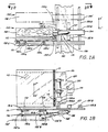
- FIGS. 2A to 2C show that the stripper 150 is connected to a projecting element 154, which in turn is fastened to bearings 155A and 155B, which comprise vertical slide rods 156A and 156B.
- the protruding element 154 allows the entire stripper 150 to be moved up and down along the slide rods 156A and 156B according to the arrows U 'and U ", this movement being caused by a control cylinder 157.
- the end of the control cylinder 157 is middle a movable rod 157R is connected to the slide 101, so that when the control cylinder 157 is actuated in the usual way (fluid pressure influencing an internally movable piston) the entire wiper moves up or down in the direction of the arrows U 'or U ".
- the upward movement of the scraper 150 leads to the fact that it also moves in the transverse direction to the transport plate 110 into the position 150 'shown in dashed lines.
- each of the light control units 102L, 102V and 103L, 103V consists of a light source and a receiving element which reacts to light emanating from the light source and reflected by one of the reflectors 171 according to FIG. 1.
- FIG. 2B shows a top view of the arrangement shown schematically in FIG. 2A. It can be seen from this that the transport plate 110 can be moved with the aid of a toothed rack 111 and a pinion 112. The pinion is driven via a gear 113 by a motor 114 which is attached to the slide 101. 2B shows the outer and inner planks 152 and 151 of the scraper 150 and the manner in which the outer planks 152-1 and 152-2 relate to the inner plank 151 using a second piston-cylinder assembly 158 are pivotable.
- the next step in the stacking cycle is to lower the stripper 150 due to the opposite operation of the control cylinder 157.
- the upper outer plank 152-1 then engages the lower outer plank 152-2 (shown in phantom) by inserting a pin 150p into a recess 150k of the lower outer plank 152-2 engages.
- the two outer planks 152-1 and 152-2 are then pivoted outward into position 152 'under the action of cylinder 158 to effect the desired alignment of the stack.
- the lower outer plank 152-2 is rotatably connected to the carriage via arms 106 as shown in FIG. 1.
- the lower outer plank has openings 152a for the light from the light control units.
- the transport plate 110 is moved back in the direction of arrow C "due to the reverse mode of operation of the motor 114.
- the correct distance between the position deposited on the stack and the edge of the stack is shown by the movement of the cylinder 158 according to FIG. 2B in the broken line
- the upper outer plank is connected to lugs 151A and 151B by means of pivotable link members 152A and 152B
- the rod 158R is connected to the articulated member 152B and, when actuated, brings it into the position 152'B shown in dashed lines. From FIG. 2B one can also see an extension 120 of the carriage 101 which has a threaded bore 130 for the Screw spindle 144 according to FIG. 1 has.
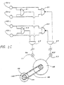
- the automatic alignment of the slide 101 in the desired stack height takes place due to the interaction of the pairs of light control units 102L, 102V and 103L, 103V with the electrical circuit shown in FIG. 2C.
- the upper light control units 102U and 103U are connected to the input terminals of an AND gate A1 and a NAND gate N1.
- the outputs of the AND gates A1 and A2 are connected to the inputs of a third AND gate A3.
- the outputs of the NAND gates N1 and N2, however, are connected to the inputs of a fourth AND gate A4.
- the downward movement of the carriage 101 is controlled by the output signal of the AND gate A3 via a switch S1.
- the upward movement of the carriage is controlled by the output signal of the AND gate A4 via a switch S2.
- the AND gates A1, A2 and A3 are active, whereas the AND gate A4 is inactive, so that a signal is generated that causes the carriage to move downward when switch S1 is closed. This movement continues until one of the receiving organs no longer receives light. It will be one of the lower receiving elements, since such one first encounters darkened conditions, which are caused, for example, by hitting the upper edge of the stack which has been formed at the stacking point P2 or by being on one hits the lower stop. In the latter case, the carriage can be caused to search for a starting position which is at a predetermined operating level by switching to an upward movement which is ended when, for example, a magnetically acting shut-off device on the stack carrier responds.
- the carriage remains in the position in which this constellation occurs because at least one of the AND elements A1 or A2 is inactive, as a result of which the AND gate A3 on the output side also becomes inactive.
- the carriage 101 therefore moves upward when the switch S2 is closed. This movement continues until two receiving elements located on the same level receive reflected light. These will be the upper receiving elements 102U and 103U, since they are the first to be affected by the reflected light, which is caused, for example, by passing through the upper edge of the stack formed at the stacking point P2 or by pointing to an upper one Bump limiting element. In the latter case, the carriage can be made to search for a starting position again.
- NAND gates N1 and N2 to control the upward movement, if only one of the upper receiving elements 102U or 103U receives light, the upward movement continues until both receiving elements receive reflected light. This will put the transport into operation plate is prevented until it is in a position in which a separation from the previously deposited position has taken place, regardless of whether it is crooked or otherwise not properly aligned.
- a DC motor is preferably used to achieve precise speed control of the transport plate 110.
- the motor causing the upward and downward movement i.e. motor 149 in Fig. 2C
- the motor causing the upward and downward movement is preferably a DC motor with conical brakes. When it is connected to the operating voltage, it swings out to the side; when it is switched off, it slides into its braked starting position.
- the scraper 150 is preferably actuated by the two fluid-controlled cylinders 157 and 158, in which the fluid is, for example, air.
- other fluid means such as e.g. Oil, it is also possible to replace the DC motor with an equivalent drive.
- the receiving members 103U and 103L are preferably fastened in such a way that they receive light beams diagonally reflected by the double row 172 of reflectors 171. This ensures proper operation even if the layer of a stack located on the transport plate has a gap between its individual components, through which the light could pass unhindered and could thus cause the transport plate to look for the wrong level. Because of the diagonal arrangement of the receiving members 103U and 103L, double reflectors are required at every height of the double row 172, so that a proper operation is ensured regardless of the setting of the stop piece 170. The outer reflectors of the double row 172 are then active when the stop piece is set at a distance from the slide, while the inner reflectors are active when the stop piece is set in the direction of the slide.
Landscapes
- Engineering & Computer Science (AREA)
- Mechanical Engineering (AREA)
- Pile Receivers (AREA)
- Stacking Of Articles And Auxiliary Devices (AREA)
Description
Die Erfindung bezieht sich auf eine Stepeleinrichtung mit einer Transportplatte zum Fördern des an einer ersten Stelle aufgenommenen und in einer Lage angeordneten Stückgutes, ferner mit Mitteln zum selbsttätigen Ausrichten der Transportplatte in einer vorbestimmten Höhenlage und mit Mitteln zum Bewegen der Transportplatte über eine zweite Stelle und zum dort erfolgenden Ablegen der erwähnten Lage als Bestandteil eines aus mehreren Lagen gebildeten Stapels, wobei Lichtsteuereinheiten zum selbsttätigen Ausrichten der Transportplatte in bezug auf die jeweils in der zweiten Stelle einzunehmende Stapelhöhe in Abhängigkeit von dem an der zweiten Stelle gegebenenfalls bereits vorhandenen Stapel vorgesehen sind.The invention relates to a stacking device with a transport plate for conveying the piece goods received at a first location and arranged in one position, further with means for automatically aligning the transport plate at a predetermined height and with means for moving the transport plate over a second location and for depositing the layer mentioned there as part of a stack formed from a plurality of layers, light control units being provided for automatically aligning the transport plate with respect to the stack height to be taken in the second position, depending on the stack that may already be present in the second position.
Eine derartige Stapeleinrichtung ist aus der DE-A-2 005 446 bekannt. Mit dieser Stapeleinrichtung wird von der Transportplatte aufgenommenes Stückgut jeweils in eine solche Höhenlage gebracht, daß nachfolgend das Ablegen auf einem bereits bestehenden Stapel möglich ist, wobei unabhängig von der jeweiligen Höhe des Stückguts und damit des Stapels die notwendige Höhenlage automatisch ermittelt wird. Dies geschieht mittels Lichtprojektoren, die einen Lichtstrahl diagonal zum Stapel zu einem fotoempfindlichen Empfänger werfen. Lichtprojektor und zugehörige Empfänger sind also getrennt voneinander angeordnet.Such a stacking device is known from DE-A-2 005 446. With this stacking device, piece goods picked up by the transport plate are each brought into such a high position that subsequent storage on an already existing stack is possible, the necessary height position being determined automatically regardless of the respective height of the piece goods and thus the stack. This is done by means of light projectors, which throw a light beam diagonally to the stack to a photosensitive receiver. The light projector and associated receiver are therefore arranged separately from one another.
Der Erfindung liegt die Aufgabe zugrunde, die bekannte Einrichtung hinsichtlich der Anordnung der Lichtsteuereinheiten zu verbessern. Dies geschieht dadurch, daß die Lichtsteuereinheiten jeweils Paare von übereinander angeordneten, als Lichtquelle und Empfangselement ausgebildeten Lichtsteuereinheiten bilden und zwei Paare nebeneinander derart angeordnet sind, daß im Zusammenwirken mit Reflektoren die Stapelhöhe an der zweiten Stelle entweder beide Paare abdeckt bzw. freigibt oder nur das untere Paar abdeckt, so daß bei Abdeckung bzw. Freigabe die Transportplatte entsprechend vertikal verschoben und bei Abdeckung nur des unteren Paares in ihrer Höhenlage festgehalten wird.The object of the invention is to improve the known device with regard to the arrangement of the light control units. This is done in that the light control units each form pairs of light control units arranged one above the other, designed as a light source and receiving element, and two pairs are arranged side by side in such a way that, in cooperation with reflectors, the stack height at the second point either covers or releases both pairs or only the lower one Pair covers, so that when the cover is released or released, the transport plate is moved vertically and is held in place only when the lower pair is covered.
Aufgrund der Zusammenfassung von Lichtquelle und Empfangselement zu einem ein Paar dieser Lichtsteuereinrichtungen bildenden Lichtsteuereinheit und der Anordnung von Lichtquelle und Empfangselement übereinander innerhalb des Paares ergibt sich eine eng geschlossene Ausführungsform für die Lichtsteuereinheiten mit gleichzeitiger Möglichkeit der Feststellung der notwendigen vertikalen Bewegungsrichtung der Transportplatte.Due to the combination of light source and receiving element to form a light control unit forming a pair of these light control devices and the arrangement of light source and receiving element one above the other within the pair, a tightly closed embodiment results for the light control units with simultaneous possibility of determining the necessary vertical direction of movement of the transport plate.
Zweckmäßig ordnet man die erste und die zweite Stelle in derselben Arbeitshöhe an, da sich auf diese Weise für das Bedienungspersonal eine gute Übersichtlichkeit ergibt.It is advisable to arrange the first and second digits at the same working height, as this provides a clear overview for the operating personnel.
Der Transportplatte kann man einen Abstreifer zuordnen, der quer zu der Transportplatte bewegbar ist. Der Abstreifer übernimmt so die genaue Ausrichtung des zu einer Lage zusammengefaßten Stückgutes an der ersten Stelle.A stripper can be assigned to the transport plate which can be moved transversely to the transport plate. The stripper thus takes over the exact alignment of the piece goods combined into one layer at the first position.
Der Abstreifer kann aus einer inneren und äußeren Planke bestehen, die die Transportplatte kreuzen.The scraper can consist of an inner and outer plank that cross the transport plate.
Um zu vermeiden, daß bei einer Auf- und Abbewegung des Abstreifers dieser einen bereits bestehenden Stapel streift und diesen möglicherweise umwirft, ordnet man den Abstreifer zweckmäßig so an, daß er in der Bewegungsrichtung der Transportplatte bewegbar ist.In order to avoid that when the scraper moves up and down it strikes an existing stack and possibly knocks it over, the scraper is expediently arranged so that it can be moved in the direction of movement of the transport plate.
Nachstehend wird die Erfindung anhand von Ausführungsbeispielen unter Bezugnahme auf die Zeichnung näher erläutert. In der Zeichnung zeigt
- Fig. 1 die Perspektiv-Teilansicht einer erfindungsgemäßen Stapeleinrichtung,
- Fig. 2A eine Teilvorderansicht, aus der Details der Befestigung und der Betätigung des Abstreifers und der Platte der Anordnung gemäß der Linie 2A-2A in der Fig. 1 zu ersehen sind,
- Fig. 2B eine Teildraufsicht der in Fig. 2A dargestellten Bestandteile gemäß der Linie 2B-2B,
- Fig. 2C den zur Lichtsteuerung gehörenden elektrischen Schaltkreis der Stapeleinrichtung gemäß Fig. 1.
- 1 is a partial perspective view of a stacking device according to the invention,
- 2A is a partial front view showing details of the attachment and actuation of the scraper and plate of the assembly along the line 2A-2A in FIG. 1,
- 2B is a partial plan view of the components shown in Fig. 2A along the line 2B-2B,
- 2C shows the electrical circuit belonging to the light control of the stacking device according to FIG. 1.
In Fig. 1 ist eine erfindungsgemäße Stapeleinrichtung 100 in der Nachbarschaft einer Fördervorrichtung 300 an einer Ladestelle P2 angeordnet dargestellt. Bei der Stapeleinrichtung 100 ist eine Transportplatte 110 gleitbar von einem Schlitten 101 getragen. Der letztere ist freitragend befestigt und in vertikaler Aufwärtsrichtung, wie durch den Pfeil A' angegeben, und in vertikaler Abwärtsrichtung, wie durch den Pfeil A" angegeben, längs nicht dargestellter Führungsschienen eines Stapelträgers 140 bewegbar.1 shows a
Der Stapelträger 140 selbst weist Seitenteile 141 und 142 sowie ein Endteil 143 auf. Im Endteil 143 und in einem gegenüberliegenden, in der Fig. 1 nicht sichtbaren Bodenteil ist eine Schraubspindel 144 drehbar befestigt. Die Schraubspindel 144 wird in üblicher Weise im Uhrzeigersinn oder im Gegenuhrzeigersinn angetrieben, beispielsweise durch einen nicht dargestellten Motor, der an einem der Seitenteile 143 oder 142 befestigt ist und über eine Kette 148 oder einen Riemen mit einem Antriebsgetriebe 146 der Schraubenspindel in Wirkverbindung steht. Die Schraubspindel 144 ist auch in einem in Fig. 1 nicht sichtbaren Ansatz des Schlittens 101 eingeschraubt, so daß bei ihrer Drehbewegung im Uhrzeigersinn oder im Gegenuhrzeigersinn dieser Schlitten nach oben oder nach unten in. Richtung der Pfeile A' oder A" bewegt wird.The
Der Schlitten 101 trägt auch einen Abstreifer 150, der aus einer inneren Planke 151 und aus äußeren Planken 151-1 und 152-2 besteht. Wie noch erläutert werden wird, sind die äußeren Planken bezüglich der inneren Planke 151 zur Seite hin in festgelegten Intervallen des Stapelzyklus bewegbar. Sowohl die innere Planke 151 als auch die äußeren Planken 151-1 und 152-2 sind in der nachstehend erläuterten Art und Weise am Schlitten 101 befestigt, wobei es sich jedoch nur um eine beispielhafte Befestigungsart handelt. Zusätzlich zum Abstreifer 150 weist die Stapeleinrichtung 100 gemäß Fig. 1 eine rückwärtige, in ihrer Lage verstellbare Musterschablonenplanke 153 auf, die dazu mitausgenutzt wird, auf der Transportplatte 110 die in gestrichelten Linien dargestellte Lage B' zu bilden.The
Beim Ausführungsbeispiel der Erfindung gemäß Fig. 1 wird von einer automatischen Lichtsteuerung Gebrauch gemacht. Als Beispiel ist angenommen, daß Lichtsteuerelemente 102 und 103 in der in Fig. 2A dargestellten Weise am Schlitten 101 angebracht sind. Die Lichtsteuerelemente arbeiten mit einem Anschlagstück 170 zusammen, das eine Mehrzahl von Reflektoren 171 aufweist, die in zwei vertikalen Spalten 172 und 173 angeordnet sind. Die Spalte 172 befindet sich mittig auf dem Anschlagstück und umfaßt eine Doppelreihe von Reflektoren 171. Die Spalte 173 ist am Rand des Anschlagstückes angeordnet und weist eine Einfachreihe von Reflektoren 171 auf. Der Grund, weswegen bei der mittleren Spalte 172 eine Doppelreihe von Reflektoren Verwendung findet, wird nachstehend näher erläutert. Das Anschlagstück 170 ist sowohl bezüglich der Oberfläche der Fördervorrichtung 300 an der Musterbildungsstelle als auch bezüglich der Stapeleinrichtung 100 einstellbar.In the embodiment of the invention shown in FIG. 1, automatic light control is used. As an example, assume that
Die Steuerung der Stapeleinrichtung 100 erfolgt von einem Steuerungskasten 180 aus. Zunächst wird jedoch eine Handkurbel 104 dazu verwendet, die rückwärtige Musterschablonenplanke 153 in die gewünschte Stellung bezüglich der inneren Planke 151 des Abstreifers 150 zu bringen. In der Praxis kann die Kante der Musterschablonenplanke 153 von der Oberfläche der Transportplatte 110 um eine vorgegebene Strecke beabstandet sein.The
Zweckmäßigerweise wird dann ein Mustertiefenschalter 105' bezüglich der Hinterseite einer angenommenen Lage B' eingestellt. Die Tiefe D der Lage B' wird dann gemessen, woraufhin die räumliche Lage des Anschlagstückes 170 unter Verwendung der Skala 174 zusammen mit einem üblichen, nicht dargestellten Zahnstangenantrieb eingestellt wird.A pattern depth switch 105 'is then expediently set with respect to the rear of an assumed position B'. The depth D of the position B 'is then measured, whereupon the spatial position of the
Am Steuerungskasten 180 ist ein Steuerungshebel 181 angebracht, der dazu verwendet wird, von Hand bestimmte Funktionen zu veranlassen. Ein Anheben des Steuerungshebels 181 führt dazu, daß der Schlitten 101 sich in Richtung A' bewegt. Ein Absenken des Hebels 181 hingegen bewirkt eine Bewegung des Schlittens 101 nach unten in Richtung des Pfeils A". Wenn der Hebel 181 in der einen Richtung horizontal bewegt wird, geht der Abstreifer 150, wie in Fig. 2B gezeigt, auseinander. Die Horizontalbewegung des Hebels 181 in der anderen Richtung führt hingegen dazu, daß der Schlitten 101 in seine Ausgangsstellung zurückkehrt, die sich an einer vorgegebenen Stelle in Höhe der Bedienungsperson befindet.A
Der Steuerungskasten 180 umfaßt auch einen Auswahlschalter 182, in dessen einer Stellung sich der automatische oder normale Betrieb abwickelt und in dessen anderer Stellung der Abstreifer, wie in Fig. 2A gezeigt, angehoben wird. Weiterer Bestandteil des Steuerungskastens 180 ist ein Geschwindigkeitswahischaiter 183, mit dessen Hilfe die Geschwindigkeit der Bewegung der Transportplatte 110 bei deren durch den Pfeil C' gekennzeichneten Auswärtshub eingestellt werden kann. Der Rückwärtshub entsprechend dem Pfeil C" wird automatisch unter allen Umständen auf einem Maximalwert gehalten. Hiermit ist der Auswärtshub für eine große Vielzahl von Lagemustern einstellbar. Weitere Bestandteile des Steuerungskastens 180 ist ein Startknopf 184, der dazu dient, die Antriebsmaschine in Gang zu setzen, sowie ein Haltknopf 185. Ein weiterer Knopf 186 dient dazu, eine zyklische Wiederholung der Lagenanordnung der Stapel festzulegen.The
Nachstehend werden Einzelheiten der Betriebsweise des Abstreifers und der Transportplatte anhand der Fig. 2A bis 2C näher erläutert. Aus der schematischen Darstellung gemäß Fig.2A sieht man, daß der Abstreifer 150 mit einem vorspringenden Element 154 verbunden ist, das seinerseits an Lagern 155A und 155B befestigt ist, die vertikale Gleitstangen 156A und 156B umfassen. Das vorspringende Element 154 gestattet es, den gesamten Abstreifer 150 längs der Gleitstangen 156A und 156B entsprechend den Pfeilen U' und U" nach oben und nach unten zu bewegen, wobei diese Bewegung durch einen Steuerzylinder 157 hervorgerufen wird. Das Ende des Steuerzylinders 157 ist mittels einer beweglichen Stange 157R mit dem Schlitten 101 verbunden, so daß bei Betätigung des Steuerzylinders 157 in üblicher Weise (Fluiddruck-Beeinflussung eines innen beweglichen Kolbens) der gesamte Abstreifer in Richtung der Pfeile U' oder U" sich nach oben oder nach unten bewegt. Die Aufwärtsbewegung des Abstreifers 150 führt dazu, daß er sich auch in Querrichtung zur Transportplatte 110 in die gestrichelt dargestellte Lage 150' bewegt.Details of the operation of the scraper and the transport plate are explained in more detail below with reference to FIGS. 2A to 2C. 2A shows that the
Es sei darauf hingewiesen, daß jede der Lichtsteuereinheiten 102L, 102V und 103L, 103V aus einer Lichtquelle und einem Empfangselement besteht, das auf von der Lichtquelle ausgehendes und von einem der Reflektoren 171 gemäß Fig. 1 reflektiertes Licht reagiert.It should be noted that each of the light control units 102L, 102V and 103L, 103V consists of a light source and a receiving element which reacts to light emanating from the light source and reflected by one of the
Fig. 2B zeigt eine Draufsicht der schematisch in Fig. 2A dargestellten Anordnung. Man erkennt daraus, daß die Transportplatte 110 mit Hilfe einer Zahnstange 111 und eines Ritzels 112 bewegbar ist. Das Ritzel wird über ein Getriebe 113 durch einen Motor 114 angetrieben, der am Schlitten 101 befestigt ist. Darüber hinaus zeigt Fig. 2B die äußeren und inneren Planken 152 und 151 des Abstreifers 150 sowie die Art und Weise, in der die äußeren Planken 152-1 und 152-2 bezüglich der inneren Planke 151 mit Hilfe einer zweiten Kolben-Zylinder-Anordnung 158 verschwenkbar sind. Wenn der Schlitten 101 sich in einer Stellung befindet, die mit Hilfe der Lichtsteuereinheiten 102 und 103 bestimmt wird, erfolgt eine Hubbewegung des Abstreifers 150 in Querbewegung bezüglich der Transportplatte 110 aufgrund der Wirkung des in Fig. 2A gezeigten Zylinders 157, woraufhin die Transportplatte unter der Wirkung des Motors 114 sich in Richtung des Pfeils C' in Fig. 2B bewegt, um dann über der Stapelstelle zu liegen.FIG. 2B shows a top view of the arrangement shown schematically in FIG. 2A. It can be seen from this that the
Der nächste Schritt des Stapelzyklus besteht in einem Absenken des Abstreifers 150 aufgrund des entgegengesetzten Betriebes des Steuerzylinders 157. Die obere äußere Planke 152-1 greift dann an der unteren äußeren Planke 152-2 (gestrichelt dargestellt) an, indem ein Stift 150p in eine Ausnehmung 150k der unteren äußeren Planke 152-2 eingreift. Die beiden äußeren Planken 152-1 und 152-2 werden dann unter der Wirkung des Zylinders 158 nach außen in eine Stellung 152' geschwenkt, um die gewünschte Ausrichtung des Stapels herbeizuführen. Es sei darauf hingewiesen, daß zu diesem Zweck die untere äußere Planke 152-2 über Arme 106, wie in Fig. 1 gezeigt, drehbar mit dem Schlitten verbunden ist. Darüber hinaus weist die untere äußere Planke Öffnungen 152a für das Licht der Lichtsteuereinheiten auf. Beim nachfolgenden Arbeitsschritt wird die Transportplatte 110 aufgrund der Rückwärtsbetriebsweise des Motors 114 in Richtung des Pfeils C" zurückbewegt. Derordnungsgemäße Abstand zwischen der auf dem Stapel abgelegten Lage und der Kante des Stapels wird durch die Bewegung des Zylinders 158 gemäß Fig. 2B in die gestrichelt dargestellte Stellung 158' bewirkt, wodurch die obere äußere Planke in die gestrichelt dargestellte Stellung 152' gelangt und daraufhin wieder in ihre Normalstellung zurückbewegt wird. Um dies zu erreichen, ist die obere äußere Planke mittels verschwenkbarer Gelenkglieder 152A und 152B mit Ansätzen 151A und 151 B verbunden. Die Stange 158R steht mit dem Gelenkglied 152B in Verbindung und bringt diese, bei Betätigung in die gestrichelt gezeichnete Stellung 152'B. Aus der Fig. 2B erkennt man auch einen Ansatz 120 des Schlittens 101, der eine mit Gewinde versehene Bohrung 130 für die Schraubspindel 144 gemäß Fig. 1 hat.The next step in the stacking cycle is to lower the
Das automatische Ausrichten des Schlittens 101 in der gewünschten Stapelhöhe erfolgt aufgrund des Zusammenwirkens der Paare von Lichtsteuereinheiten 102L, 102V und 103L, 103V mit dem in Fig. 2C dargestellten elektrischen Schaltkreis. Die oberen Lichtsteuereinheiten 102U und 103U sind mit den Eingangsanschlüssen eines AND-Gliedes A1 und eines NAND-Gliedes N1 verbunden. Die Ausgänge der AND-Glieder A1 und A2 sind mit den Eingängen eines dritten AND-Gliedes A3 verbunden. Die Ausgänge der NAND-Glieder N1 und N2 hingegen sind an die Eingänge eines vierten AND-Gliedes A4 angeschlossen.The automatic alignment of the
Die Abwärtsbewegung des Schlittens 101 wird durch das Ausgangssignal des AND-Gliedes A3 über einen Schalter S1 gesteuert. Die Aufwärtsbewegung des Schlittens hingegen wird durch das Ausgangssignal des AND-Gliedes A4 über einen Schalter S2 gesteuert.The downward movement of the
Das bedeutet, daß dann, wenn der Motor 149 (der am Stapelträger 140 gemäß Fig. 1 befestigt sein kann) über den Schalter S1 an Betriebsspannung gelegt wird, er das Getriebe 146 antreibt, das mit der Schraubspindel 144 gemäß Fig. 1, die im Lager 145 gehalten wird, in Wirkverbindung steht.This means that when the motor 149 (which can be fastened to the
Wenn alle Empfangsorgane der Lichtsteuereinheiten Licht empfangen, das an die Reflektoren 171 gemäß Fig. 1 ausgesendet und von dort zurückreflektiert worden ist, sind die AND-Glieder A1, A2 und A3 aktiv, wogegen das AND-Glied A4 inaktiv ist, sodaß ein Signal erzeugt wird, das die Abwärtsbewegung des Schlittens bewirkt, wenn der Schalter S1 geschlossen ist. Diese Bewegung wird fortgesetzt, bis eines der Empfangsorgane kein Licht mehr empfängt. Es wird sich dabei um eines der unteren Empfangsorgane handeln, da ein solches als erstes abgedunkelte Verhältnisse antrifft, die beispielsweise dadurch hervorgerufen werden, daß es auf die obere Kante des Stapels trifft, der an der Stapelungsstelle P2 gebildet worden ist, oder indem es auf einen unteren Anschlag trifft. Im letzgenannten Fall kann der Schlitten veranlaßt werden, eine Ausgangsstellung zu suchen, die sich auf einem vorgegebenen Bedienungsniveau befindet, indem eine Umschaltung auf Aufwärtsbewegung erfolgt, die dann beendet ist, wenn beispielsweise ein magnetisch wirkendes Abschaltorgan am Stapelträger anspricht.If all receiving elements of the light control units receive light which has been emitted to the
Wenn eines oder beide der unteren Empfangsorgane 102L oder 103L kein Licht empfangen, die beiden oberen Empfangsorgane 102U und 103U hingegen von reflektiertem Licht getroffen werden, bleibt der Schlitten in derjenigen Stellung, in der sich diese Konstellation einstellt, da wenigstens eines der AND-Glieder A1 oder A2 inaktiv ist, wodurch das ausgangsseitige AND-Glied A3 ebenfalls in den inaktiven Zustand gelangt.If one or both of the lower receiving elements 102L or 103L receive no light, but the two
Wenn umgekehrt alle der Empfangsorgane kein Licht empfangen, sind die AND-Glieder A und A2 inaktiv, die NAND-Glieder N1 und N2 hingegen sind aktiv. Der Schlitten 101 bewegt sich daher nach oben, wenn der Schalter S2 geschlossen ist. Diese Bewegung dauert so lange an, bis zwei sich auf demselben Niveau befindende Empfangsorgane reflektiertes Licht empfangen. Es werden dies die oberen Empfangsorgane 102U und 103U sein, da sie als erste von dem reflektierten Licht beaufschlagt werden, was beispielsweise dadurch zustande kommt, daß sie die obere Kante des an der Stapelungsstelle P2 gebildeten Stapels passieren, oder dadurch, daß sie auf ein oberes Begrenzungsorgan stoßen. Im letztgenannten Fall kann der Schlitten wieder dazu veranlaßt werden, eine Ausgangsstellung zu suchen.Conversely, if all of the receiving elements receive no light, the AND gates A and A2 are inactive, while the NAND gates N1 and N2 are active. The
Wegen der Verwendung der NAND-Glieder N1 und N2 zum Steuern der Aufwärtsbewegung wird, wenn lediglich eines der oberen Empfangsorgane 102U oder 103U Licht empfängt, die Aufwärtsbewegung fortgesetzt, bis beide Empfangsorgane reflektiertes Licht aufnehmen. Hierdurch wird eine Inbetriebnahme der Transportplatte so lange verhindert, bis sie sich in einer Stellung befindet, in der eine Trennung von der vorher abgelegten Lage stattgefunden hat, und zwar unabhängig davon, ob diese schief liegt oder auf andere Weise nicht ordnungsgemäß ausgerichtet ist.Because of the use of NAND gates N1 and N2 to control the upward movement, if only one of the
Zur Erzielung einer exakten Geschwindigkeitssteuerung der Transportplatte 110 wird vorzugsweise ein Gleichstrommotor eingesetzt. Bei dem die Aufwärts- und Abwärtsbewegung bewirkenden Motor (d.h. dem Motor 149 gemäß Fig. 2C) handelt es sich vorzugsweise um einen Gleichstrommotor mit konischen Bremsen. Wenn dieser an Betriebsspannung gelegt wird, schwenkt er zur Seite aus, beim Abschalten gleitet er in seine gebremste Ausgangsstellung. Ein ähnliches Ergebnis könnte mit einem entsprechenden Kupplungs- und Bremssystem erreicht werden. Der Abstreifer 150 wird vorzugsweise durch die zwei Fluid-gesteuerten Zylinder 157 und 158 betätigt, bei denen das Fluid beispielsweise Luft ist. Es können jedoch auch andere Fluidmittel, wie z.B. Öl, verwendet werden, auch ist es möglich, den Gleichstrommotor durch einen gleichwertigen Antrieb zu ersetzen.A DC motor is preferably used to achieve precise speed control of the
Es sei darauf hingewiesen, daß die Empfangsorgane 103U und 103L vorzugsweise so befestigt sind, daß sie von der Doppelreihe 172 von Reflektoren 171 diagonal reflektierte Lichtstrahlen aufnehmen. Hierdurch ist eine ordnungsgemäße Arbeitsweise auch dann gewährleistet, wenn die auf der Transportplatte befindliche Lage eines Stapels einen Spalt zwischen einzelnen ihrer Bestandteile aufweist, durch den das Licht ungehindert hindurchtreten und damit bewirken könnte könnte, daß die Transportplatte sich ein falsches Niveau sucht. Wegen der Diagonalanordnung der Empfangsorgane 103U und 103L werden Doppelreflektoren in jeder Höhe der Doppelreihe 172 benötigt, damit unabhängig von der Einstellung des Anschlagstückes 170 eine ordnungsgemäße Arbeitsweise sichergestellt ist. Damit sind die äußeren Reflektoren der Doppelreihe 172 dann aktiv, wenn das Anschlagstück vom Schlitten beabstandet eingestellt ist, die inneren Reflektoren hingegen sind dann aktiv, wenn das Anschlagstück in Richtung zum Schlitten hin eingestellt ist.It should be noted that the receiving members 103U and 103L are preferably fastened in such a way that they receive light beams diagonally reflected by the
Claims (5)
Applications Claiming Priority (2)
| Application Number | Priority Date | Filing Date | Title |
|---|---|---|---|
| US95775878A | 1978-11-06 | 1978-11-06 | |
| US957758 | 1978-11-06 |
Publications (4)
| Publication Number | Publication Date |
|---|---|
| EP0010778A2 EP0010778A2 (en) | 1980-05-14 |
| EP0010778A3 EP0010778A3 (en) | 1980-09-03 |
| EP0010778B1 EP0010778B1 (en) | 1983-11-09 |
| EP0010778B2 true EP0010778B2 (en) | 1990-11-07 |
Family
ID=25500090
Family Applications (1)
| Application Number | Title | Priority Date | Filing Date |
|---|---|---|---|
| EP19790104349 Expired - Lifetime EP0010778B2 (en) | 1978-11-06 | 1979-11-06 | Piling arrangement |
Country Status (4)
| Country | Link |
|---|---|
| EP (1) | EP0010778B2 (en) |
| JP (1) | JPS55123821A (en) |
| AU (1) | AU535078B2 (en) |
| DE (2) | DE2944556A1 (en) |
Families Citing this family (1)
| Publication number | Priority date | Publication date | Assignee | Title |
|---|---|---|---|---|
| CN102502268B (en) * | 2011-10-19 | 2013-12-18 | 中国建材国际工程集团有限公司 | Method for positioning first glass piece in system of stacking glass by mechanical arm |
Family Cites Families (3)
| Publication number | Priority date | Publication date | Assignee | Title |
|---|---|---|---|---|
| SE322731B (en) * | 1969-03-27 | 1970-04-13 | Weiner K | |
| DE2558233A1 (en) * | 1975-12-23 | 1977-07-07 | Herbert Kappenberg | Palletised container stacking machine - has packing plate and ejector delivering layers movable vertically at least for stack height |
| US4068765A (en) * | 1976-04-29 | 1978-01-17 | Vanguard Machinery Corporation | Stacking of materials |
-
1979
- 1979-10-22 AU AU52005/79A patent/AU535078B2/en not_active Ceased
- 1979-11-05 DE DE19792944556 patent/DE2944556A1/en not_active Withdrawn
- 1979-11-05 JP JP14215079A patent/JPS55123821A/en active Pending
- 1979-11-06 DE DE7979104349T patent/DE2966393D1/en not_active Expired
- 1979-11-06 EP EP19790104349 patent/EP0010778B2/en not_active Expired - Lifetime
Also Published As
| Publication number | Publication date |
|---|---|
| AU5200579A (en) | 1980-05-15 |
| EP0010778A3 (en) | 1980-09-03 |
| JPS55123821A (en) | 1980-09-24 |
| DE2944556A1 (en) | 1980-05-14 |
| EP0010778B1 (en) | 1983-11-09 |
| EP0010778A2 (en) | 1980-05-14 |
| DE2966393D1 (en) | 1983-12-15 |
| AU535078B2 (en) | 1984-03-01 |
Similar Documents
| Publication | Publication Date | Title |
|---|---|---|
| EP4005955B1 (en) | Machine for sorting and stacking boxes with tiltable side panels | |
| DE3613316C1 (en) | Device for cutting stacked, sheet-like material | |
| DE3702965C2 (en) | ||
| DE2242304C3 (en) | Sawing machine | |
| DE3217385A1 (en) | METHOD FOR REMOVING AT LEAST ONE FLAT OBJECT FROM A STACK, AND APPLYING THE METHOD | |
| DE3430029C2 (en) | Device for loading multi-sizing saws with table or plate-shaped workpieces arranged on a lifting table | |
| DE4125342C2 (en) | Positioning device for palletizing machines | |
| EP0010778B2 (en) | Piling arrangement | |
| CH620883A5 (en) | Device for stacking drums provided with stacking grooves | |
| DE1556119C3 (en) | Method and device for laying layers of boards parallel to one another with a predetermined total width that can be selected | |
| EP0557783B1 (en) | Device for forming cigarette blocks | |
| DE2905852A1 (en) | METHOD AND DEVICE FOR THE FORMATION OF A STACK FROM A DETERMINED NUMBER OF PACKAGES | |
| EP0822739B1 (en) | Automated apparatus for printed circuit board inspection | |
| EP0020287A1 (en) | Device for unstacking piles of piece-goods | |
| EP0297201A1 (en) | Device for feeding lengths of longitudinal elements to a grid-welding machine | |
| AT384968B (en) | Device for supplying cut-to-length longitudinal elements to the entry of a grating welding machine | |
| DE9109971U1 (en) | Device for compacting reams of paper | |
| DE4227508C2 (en) | Device for cutting stacked sheets of paper, cardboard or the like | |
| DE1536974A1 (en) | Method for stacking print layers continuously transported one after the other and device for its implementation | |
| DE1066478B (en) | Machine for placing containers in a common packaging container | |
| DE3227973A1 (en) | METHOD AND DEVICE FOR ALIGNING THE ARCHES OF A STACK | |
| DE2631789C3 (en) | Conveyor device for injection molded parts ejected from an injection mold | |
| DE1532102C3 (en) | Machine for stacking cigarettes in vertically moving collecting bins | |
| DE2812518C2 (en) | Device for pre-cutting sideboards for a full creel system | |
| DE929850C (en) | Stack feed device for sheet processing machines, especially printing machines |
Legal Events
| Date | Code | Title | Description |
|---|---|---|---|
| PUAI | Public reference made under article 153(3) epc to a published international application that has entered the european phase |
Free format text: ORIGINAL CODE: 0009012 |
|
| AK | Designated contracting states |
Designated state(s): DE FR GB IT NL |
|
| PUAL | Search report despatched |
Free format text: ORIGINAL CODE: 0009013 |
|
| 17P | Request for examination filed |
Effective date: 19801104 |
|
| ITF | It: translation for a ep patent filed | ||
| GRAA | (expected) grant |
Free format text: ORIGINAL CODE: 0009210 |
|
| AK | Designated contracting states |
Designated state(s): DE FR GB IT NL |
|
| ET | Fr: translation filed | ||
| REF | Corresponds to: |
Ref document number: 2966393 Country of ref document: DE Date of ref document: 19831215 |
|
| PLBI | Opposition filed |
Free format text: ORIGINAL CODE: 0009260 |
|
| 26 | Opposition filed |
Opponent name: SEITZ ENZINGER NOLL MASCHINENBAU AG Effective date: 19840725 |
|
| PGFP | Annual fee paid to national office [announced via postgrant information from national office to epo] |
Ref country code: NL Payment date: 19891130 Year of fee payment: 11 |
|
| PUAH | Patent maintained in amended form |
Free format text: ORIGINAL CODE: 0009272 |
|
| STAA | Information on the status of an ep patent application or granted ep patent |
Free format text: STATUS: PATENT MAINTAINED AS AMENDED |
|
| 27A | Patent maintained in amended form |
Effective date: 19901107 |
|
| AK | Designated contracting states |
Kind code of ref document: B2 Designated state(s): DE FR GB IT NL |
|
| NLR2 | Nl: decision of opposition | ||
| EN3 | Fr: translation not filed ** decision concerning opposition | ||
| PG25 | Lapsed in a contracting state [announced via postgrant information from national office to epo] |
Ref country code: FR Effective date: 19910329 |
|
| PGFP | Annual fee paid to national office [announced via postgrant information from national office to epo] |
Ref country code: FR Payment date: 19910329 Year of fee payment: 12 |
|
| NLR3 | Nl: receipt of modified translations in the netherlands language after an opposition procedure | ||
| PG25 | Lapsed in a contracting state [announced via postgrant information from national office to epo] |
Ref country code: NL Effective date: 19910601 |
|
| NLV4 | Nl: lapsed or anulled due to non-payment of the annual fee | ||
| PGFP | Annual fee paid to national office [announced via postgrant information from national office to epo] |
Ref country code: GB Payment date: 19921222 Year of fee payment: 14 |
|
| PGFP | Annual fee paid to national office [announced via postgrant information from national office to epo] |
Ref country code: DE Payment date: 19930108 Year of fee payment: 13 |
|
| REG | Reference to a national code |
Ref country code: FR Ref legal event code: ST |
|
| PG25 | Lapsed in a contracting state [announced via postgrant information from national office to epo] |
Ref country code: GB Effective date: 19931106 |
|
| PG25 | Lapsed in a contracting state [announced via postgrant information from national office to epo] |
Ref country code: DE Effective date: 19940503 |
|
| GBPC | Gb: european patent ceased through non-payment of renewal fee |
Effective date: 19931106 |