EP0010579B1 - Verfahren zur Herstellung von Hochdruckschläuchen und Vorrichtung zur Durchführung des Verfahrens - Google Patents
Verfahren zur Herstellung von Hochdruckschläuchen und Vorrichtung zur Durchführung des Verfahrens Download PDFInfo
- Publication number
- EP0010579B1 EP0010579B1 EP79102879A EP79102879A EP0010579B1 EP 0010579 B1 EP0010579 B1 EP 0010579B1 EP 79102879 A EP79102879 A EP 79102879A EP 79102879 A EP79102879 A EP 79102879A EP 0010579 B1 EP0010579 B1 EP 0010579B1
- Authority
- EP
- European Patent Office
- Prior art keywords
- pressure
- bearing layer
- heating
- substrate
- carrier
- Prior art date
- Legal status (The legal status is an assumption and is not a legal conclusion. Google has not performed a legal analysis and makes no representation as to the accuracy of the status listed.)
- Expired
Links
- 238000000034 method Methods 0.000 title claims abstract description 31
- 239000000463 material Substances 0.000 claims abstract description 11
- 239000000853 adhesive Substances 0.000 claims abstract description 8
- 230000001070 adhesive effect Effects 0.000 claims abstract description 8
- 229920001169 thermoplastic Polymers 0.000 claims abstract description 8
- 229920002635 polyurethane Polymers 0.000 claims abstract description 6
- 239000004814 polyurethane Substances 0.000 claims abstract description 6
- 239000004416 thermosoftening plastic Substances 0.000 claims abstract description 5
- 229920000728 polyester Polymers 0.000 claims abstract description 4
- 238000010438 heat treatment Methods 0.000 claims description 18
- 239000002184 metal Substances 0.000 claims description 4
- 239000002904 solvent Substances 0.000 claims description 3
- 239000010410 layer Substances 0.000 claims 14
- 239000012790 adhesive layer Substances 0.000 claims 1
- 229920002994 synthetic fiber Polymers 0.000 claims 1
- 239000004033 plastic Substances 0.000 abstract description 9
- 229920003023 plastic Polymers 0.000 abstract description 9
- 239000000758 substrate Substances 0.000 abstract 8
- 238000000576 coating method Methods 0.000 abstract 3
- 239000011248 coating agent Substances 0.000 abstract 2
- 229920000642 polymer Polymers 0.000 abstract 1
- 239000007921 spray Substances 0.000 description 10
- 238000001125 extrusion Methods 0.000 description 4
- 238000004804 winding Methods 0.000 description 3
- 229910000831 Steel Inorganic materials 0.000 description 2
- 238000004519 manufacturing process Methods 0.000 description 2
- 239000010959 steel Substances 0.000 description 2
- 239000000126 substance Substances 0.000 description 2
- 230000002411 adverse Effects 0.000 description 1
- 239000000969 carrier Substances 0.000 description 1
- 238000001816 cooling Methods 0.000 description 1
- 230000006866 deterioration Effects 0.000 description 1
- 230000000694 effects Effects 0.000 description 1
- 238000005516 engineering process Methods 0.000 description 1
- 238000000605 extraction Methods 0.000 description 1
- 230000012447 hatching Effects 0.000 description 1
- 230000006698 induction Effects 0.000 description 1
- 230000005865 ionizing radiation Effects 0.000 description 1
- 239000007788 liquid Substances 0.000 description 1
- 239000000155 melt Substances 0.000 description 1
- 230000000149 penetrating effect Effects 0.000 description 1
- 239000011527 polyurethane coating Substances 0.000 description 1
- 230000036316 preload Effects 0.000 description 1
- 230000005855 radiation Effects 0.000 description 1
- 230000001105 regulatory effect Effects 0.000 description 1
Images

Classifications
-
- F—MECHANICAL ENGINEERING; LIGHTING; HEATING; WEAPONS; BLASTING
- F16—ENGINEERING ELEMENTS AND UNITS; GENERAL MEASURES FOR PRODUCING AND MAINTAINING EFFECTIVE FUNCTIONING OF MACHINES OR INSTALLATIONS; THERMAL INSULATION IN GENERAL
- F16L—PIPES; JOINTS OR FITTINGS FOR PIPES; SUPPORTS FOR PIPES, CABLES OR PROTECTIVE TUBING; MEANS FOR THERMAL INSULATION IN GENERAL
- F16L11/00—Hoses, i.e. flexible pipes
- F16L11/04—Hoses, i.e. flexible pipes made of rubber or flexible plastics
- F16L11/08—Hoses, i.e. flexible pipes made of rubber or flexible plastics with reinforcements embedded in the wall
- F16L11/085—Hoses, i.e. flexible pipes made of rubber or flexible plastics with reinforcements embedded in the wall comprising one or more braided layers
-
- B—PERFORMING OPERATIONS; TRANSPORTING
- B29—WORKING OF PLASTICS; WORKING OF SUBSTANCES IN A PLASTIC STATE IN GENERAL
- B29C—SHAPING OR JOINING OF PLASTICS; SHAPING OF MATERIAL IN A PLASTIC STATE, NOT OTHERWISE PROVIDED FOR; AFTER-TREATMENT OF THE SHAPED PRODUCTS, e.g. REPAIRING
- B29C48/00—Extrusion moulding, i.e. expressing the moulding material through a die or nozzle which imparts the desired form; Apparatus therefor
- B29C48/15—Extrusion moulding, i.e. expressing the moulding material through a die or nozzle which imparts the desired form; Apparatus therefor incorporating preformed parts or layers, e.g. extrusion moulding around inserts
- B29C48/151—Coating hollow articles
-
- B—PERFORMING OPERATIONS; TRANSPORTING
- B05—SPRAYING OR ATOMISING IN GENERAL; APPLYING FLUENT MATERIALS TO SURFACES, IN GENERAL
- B05D—PROCESSES FOR APPLYING FLUENT MATERIALS TO SURFACES, IN GENERAL
- B05D1/00—Processes for applying liquids or other fluent materials
- B05D1/26—Processes for applying liquids or other fluent materials performed by applying the liquid or other fluent material from an outlet device in contact with, or almost in contact with, the surface
- B05D1/265—Extrusion coatings
-
- B—PERFORMING OPERATIONS; TRANSPORTING
- B05—SPRAYING OR ATOMISING IN GENERAL; APPLYING FLUENT MATERIALS TO SURFACES, IN GENERAL
- B05D—PROCESSES FOR APPLYING FLUENT MATERIALS TO SURFACES, IN GENERAL
- B05D2254/00—Tubes
-
- B—PERFORMING OPERATIONS; TRANSPORTING
- B05—SPRAYING OR ATOMISING IN GENERAL; APPLYING FLUENT MATERIALS TO SURFACES, IN GENERAL
- B05D—PROCESSES FOR APPLYING FLUENT MATERIALS TO SURFACES, IN GENERAL
- B05D3/00—Pretreatment of surfaces to which liquids or other fluent materials are to be applied; After-treatment of applied coatings, e.g. intermediate treating of an applied coating preparatory to subsequent applications of liquids or other fluent materials
- B05D3/02—Pretreatment of surfaces to which liquids or other fluent materials are to be applied; After-treatment of applied coatings, e.g. intermediate treating of an applied coating preparatory to subsequent applications of liquids or other fluent materials by baking
- B05D3/0218—Pretreatment, e.g. heating the substrate
-
- B—PERFORMING OPERATIONS; TRANSPORTING
- B05—SPRAYING OR ATOMISING IN GENERAL; APPLYING FLUENT MATERIALS TO SURFACES, IN GENERAL
- B05D—PROCESSES FOR APPLYING FLUENT MATERIALS TO SURFACES, IN GENERAL
- B05D7/00—Processes, other than flocking, specially adapted for applying liquids or other fluent materials to particular surfaces or for applying particular liquids or other fluent materials
- B05D7/14—Processes, other than flocking, specially adapted for applying liquids or other fluent materials to particular surfaces or for applying particular liquids or other fluent materials to metal, e.g. car bodies
-
- B—PERFORMING OPERATIONS; TRANSPORTING
- B29—WORKING OF PLASTICS; WORKING OF SUBSTANCES IN A PLASTIC STATE IN GENERAL
- B29C—SHAPING OR JOINING OF PLASTICS; SHAPING OF MATERIAL IN A PLASTIC STATE, NOT OTHERWISE PROVIDED FOR; AFTER-TREATMENT OF THE SHAPED PRODUCTS, e.g. REPAIRING
- B29C48/00—Extrusion moulding, i.e. expressing the moulding material through a die or nozzle which imparts the desired form; Apparatus therefor
- B29C48/03—Extrusion moulding, i.e. expressing the moulding material through a die or nozzle which imparts the desired form; Apparatus therefor characterised by the shape of the extruded material at extrusion
- B29C48/09—Articles with cross-sections having partially or fully enclosed cavities, e.g. pipes or channels
Definitions
- the invention relates to a process for the production of high-pressure hoses with an inner core and a top cover adhering well to this, each made of thermoplastic plastic, in particular polyurethane or thermoplastic polyester and a pressure carrier constructed from metal wires and arranged between the inner core and top cover, in which starting from or already with the inner core reinforced with the print carrier, the top cover is extruded onto the print carrier heated to the working temperature of the spray head by means of a spray head, the invention also relates to a device for carrying out the method with a spray head for the top cover, a heating device for the print carrier, and an unwinding station for the inner core armored with the pressure carrier and an extraction device for the finished pressure hose and a vacuum station connected to the heating device.
- a process of this type is known from DE-C-2 026 814.
- the aim here is to create an adhesive bond between a polyurethane coating and a metallic carrier, which does not show any signs of deterioration or fatigue even when subjected to high mechanical and / or chemical stress, for example due to overheated steam.
- Example 4 there describes how this method can be successfully used in a plastic hose in which pressure-bearing helical steel wires which lie directly next to one another serve as pressure carriers. It has been shown that this previously known method does not lead to permanent sheathing in high-pressure hoses.
- a method which relates to low-pressure hoses, in which the pressure carrier has a relatively large mesh size, but in which the adhesion of the top cover is not achieved so much on the pressure carrier as on the inner core shall be.
- the inner tube is pressurized there and externally heated to such an extent that it can step out through the gaps or meshes of the pressure carrier under the effect of the inner pressure, whereupon the outer envelope tube is then applied.
- An adhesive bond with the enveloping tube should then be achieved at the points of passage of the inner tube through the pressure carrier.
- a similar process is known from DE-A-2 342 133.
- DE-A1-2 550 664 describes a method which relates to a hose carrying pressure medium, in particular a hydraulic hose, that is to say it comes close to the class of high-pressure hoses which are addressed by this invention.
- a hose carrying pressure medium in particular a hydraulic hose
- the extrusion of the sheath results in insufficient cohesion with the inner tube for handling.
- special plastics are proposed there, which are ultimately to be injured by ionizing radiation; this is intended to achieve a permanent adhesive bond between the inner hose and the hose top cover.
- the task remains to be solved to create a method of the type mentioned at the outset, by means of which a permanent adhesive bond of the top cover to the tube interior is achieved in the case of high-pressure tubes.
- a high kink and pulse resistance of the high-pressure hose is desirable.
- These mechanical-elastic properties require an intimate bond between the inner soul and the top cover. Therefore, there is in particular the task of creating a method of the type mentioned in such a way that, despite the necessary mesh size of the pressure medium of a high-pressure hose, an intimate, permanent bond between the inner core and the top cover is achieved.
- This object is achieved in that a pressure carrier made of folded and braided wire layers is used, that the pressure carrier located on the inner core is biased in the longitudinal direction of the hose by applying a tensile force is and then the heating takes place approximately at the temperature of the extrudate or the spray head, whereby the material of the inner core is pressed partially through the perforations of the pressure carrier, and that a vacuum is then applied simultaneously with the extrusion of the top cover around the pressure carrier.
- an adhesive substance in particular a polyurethane adhesive, is applied to the print carrier before it is heated.
- the print carrier is treated with a solvent before heating.
- the pressure medium can be heated by flame rings.
- DE-C-2 026 814, DE-A-1 504 098 and DE-A-2 342 133 also describe suitable devices for carrying out the methods described therein.
- the devices have a spray head for the top cover, a heating device for the pressure carrier and a removal device for the finished pressure hose. It is also common for the inner core of this device, which is reinforced with the pressure carrier, to be supplied by an unwinding station.
- DE-A-1 504 098 also discloses the possibility of closing the annulus of the spray head to a vacuum source.
- the object is to develop a device of this type in such a way that it is suitable for carrying out the method according to the invention, in particular also in its special embodiments.
- the proposed solution to this problem according to the invention now consists in a device of the type mentioned above, which additionally has a braking and synchronizing device which adjoins the unwinding station.
- the braking and synchronizing device ensures the prestressing of the pressure carrier from the inner core which is necessary according to the invention.
- a flame station which consists of one or more flame rings, has proven to be particularly effective as a heating device. This is surprising since flame treatment is not common in plastics technology. However, it has been forced that the method according to the invention can be carried out particularly well with it.
- a pressure hose from various plastic materials of the inner core and the top cover, which form an intimate bond through the metallic pressure carrier, which jumps the properties of such a pressure hose in terms of kink resistance, flexibility and pressure resistance elevated.
- the compressive strength can also be increased, since a carrier with narrow openings can be used as the metallic pressure carrier, for example a carrier made of tightly woven or woven wire layers.
- the residual moisture of any remaining solvent residues and the air in the winding layers of the carrier are drawn off before passing through the extruder's spray head.
- the steel wire layers directly in front of the spray head are advantageously heated or flamed by means of one or more flame rings.
- the temperature corresponds approximately to the temperature of the spray head. It is advantageously achieved by this flaming that the drawing greases located on the metal wires, which interfere with the desired firm connection between the top cover and the inner core, are burned off.
- the inner core which is under radial prestress, relaxes in the direction of the pressure carrier during the flame process, the inner core or the surface of the inner core at least partially softening and penetrating through the gaps or openings in the metallic carrier. In this way, the material of the inner core melts with the simultaneously extruded material of the top cover to form an intimate bond, i.e. a fused connection is created.
- 1 and 2 show in cross section two pressure hoses produced according to the method according to the invention.
- the pressure hose according to FIG. 1 consists of a top cover 1, which preferably consists of polyurethane or thermoplastic polyester.
- a metal carrier which here consists of individual wires, which are arranged in wire layers 3, 4, serves as the pressure carrier of the pressure hose. The alternating position of the wire layers or wire strips is shown.
- the inner core 2 of the pressure hose also consists of a thermoplastic polymer.
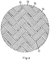
- the individual wire layers 13, 14 of a metallic carrier are shown in FIG. 3, for example.
- This metallic carrier consists of intertwined or ver woven wire layers 13, 14 which are connected to one another in such a way that small, regular diamond-shaped openings 15, 16, 17 are formed within the overall surface of the carrier. These openings 15, 16, 17 are essential for carrying out the method according to the invention. Because when the inner soul 2 is softened, the material of the inner soul enters it ; Areas 5, 6, 7 of such openings ( Figure 1) through the metallic support and forms an intimate bond with the material of the top cover applied from the outside, which is characterized in Figure 1 by the double hatching of the areas 5, 6 and 7.
- FIG. 2 also shows a cross section through a pressure hose, produced by the inventive method.
- the pressure hose consists of a top cover 8 and an inner core 9, between which in turn a carrier, preferably a metallic carrier, consisting of wire layers 10, 11 is arranged.
- the wire bobbin layer is again identified by the reference number 10.
- the individual wires of the metallic carrier form openings, which can be distributed over them in a pattern, for example.
- the material of the inner core 9 passes through the perforations of the carrier 10, 11 when softened and pretensioned and connects to the material of the top cover 8 on the outer surface of the carrier to an intimate bond, which is indicated in Figure 2 by the dotted areas.
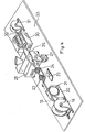
- FIG. 4 shows an apparatus for performing the method according to the invention.
- the metallic carrier 19, which has already been pulled onto an inner core, is wound on a drum 18.
- the carrier 19 is drawn off from this take-off drum 18 by means of a braking and synchronizing device 20 which, for example, has a brake disc around which the carrier 19 is looped to form a loop 21.
- a braking and synchronizing device 20 which, for example, has a brake disc around which the carrier 19 is looped to form a loop 21.
- the withdrawal voltage or the withdrawal speed of the carrier 19 can be regulated accordingly, in particular the carrier 19 is given a preload due to the braking.
- This braking and synchronization device 20 is followed by a flame station 22, which preferably consists of two flame rings 23, 24, through which the carrier 19 together with the inner core runs centrally.
- the flame station 22 is followed by a vacuum station 26, which is preferably formed from a vacuum tube to which a vacuum pump 27 is connected via a hose line 28.
- a vacuum station 26 After the vacuum station 26, there follows the extrusion station 25 with spray head 29 for applying the top cover to the carrier 19.
- the extrusion station 25 is followed by a take-off station 30, to which the transport of the finished pressure hose is accomplished by pulling the carrier through the various stations.
- a winding device 31 for winding the finished pressure hose 32.
- All of the units mentioned can preferably be arranged in a linear arrangement, as shown in FIG. 4, in the pulling direction of the carrier 19 on a common base plate which bears the reference number 33.
- the heating device can also consist of induction heating, infrared heating or hot air heating.
Landscapes
- Engineering & Computer Science (AREA)
- Mechanical Engineering (AREA)
- General Engineering & Computer Science (AREA)
- Extrusion Moulding Of Plastics Or The Like (AREA)
- Laminated Bodies (AREA)
- Lining Or Joining Of Plastics Or The Like (AREA)
- Rigid Pipes And Flexible Pipes (AREA)
Description
- Die Erfindung betrifft ein Verfahren zur Herstellung von Hochdruckschläuchen mit einer Innenseele und einer an dieser gut haftenden Oberdecke, jeweils aus thermoplatischem Kunststoff, insbesondere aus Polyurethan oder thermoplastischem Polyester und einem aus Metalldrähten aufgebauten, zwischen Innenseele und Oberdecke angeordneten Druckträger, bei dem ausgehend von oder bereits mit dem Druckträger armierten Innenseele die Oberdecke mittels eines Spritzkopfes auf den etwa auf die Arbeitstemperatur des Spritzkopfes erhitzten Druckträger aufextrudiert wird, Außerdem betrifft die Erfindung eine Vorrichtung zur Durchführung des Verfahrens mit einem Spritzkopf für die Oberdecke, einer Erhitzungseinrichtung für den Druckträger, einer Abwickelstation für die mit dem Druckträger armierte Innenseele und einer Abzugseinrichtung für den fertigen Druckschlauch und einer sich an die Erhitzungseinrichtung anschließenden Vakuumstation.
- Aus der DE-C-2 026 814 ist ein Verfahren dieser Gattung bekannt. Dort geht es darum, einen Haftverbund zwischen einem Polyurethanüberzug und einem metallischen Träger zu schaffen, der auch bei hoher mechanischer und/oder chemischer Beanspruchung, beispielsweise einer solchen durch überhitzten Wasserdampf, keine Zerfall- oder Ermüdungserscheinungen zeigt. so ist unter dem dortigen Beispiel 4 beschrieben, wie dieses Verfahren bei einem Kunststoffschlauch, bei dem drucktragende schraubenlinienförmige Stahldrähte, die unmittelbar aneinanderliegen, als Drucktrager dienen, erfolgreich eingesetzt werden kann. Es hat sich gezeigt, daß dieses vorbekannte Verfahren bei Hochdruckschläuchen nicht zur einer dauerhaften Ummantelung führt.
- Aus der DE-A-1 504 098 ist ein Verfahren bekannt, das sich auf Niederdruckschläuche bezieht, bei denen also der Druckträger eine relativ große Maschenweite aufweist, bei dem aber die Haftung der Oberdecke nicht so sehr an den Druckträger als vielmehr auf der Innenseele erzielt werden soll. Dazu wird der Innenschlauch dort mit einem Druckmittel beaufschlagt und äußerlich soweit erwärmt, daß er unter der Wirkung des Innendrucks durch die Lücken bzw. Maschen des Druckträgers nach außen treten kann, worauf dann der äußere Hüllschlauch aufgebracht wird. An den Durchtrittsstellen des Innenschlauches durch den Druckträger soll dann ein Haftverbund mit dem Hüllschlauch erreicht werden. Ein ähnliches Verfahren ist aus der DE-A-2 342 133 bekannt. Dort wird dann auf Blatt 9 der Beschreibung angegeben, daß beispielsweise ein Innendruck von 140 kp/cm2 erforderlich ist. Außerdem wird der Innenschlauch dabei in einen Ofen von einer Temperatur von 400°C eingeführt. Infolge dieser extremen Erhitzung ist unmittelbar anschließend eine Flüssigkeitskühlung vorgeschlagen. Insbesondere das letztere Beispiel zeigt, welchen Belastungen der Innenschlauch ausgesetzt ist und welcher vorrichtungsmäßiger Aufwand dazu getrieben werden muß. Selbst diese nachteiligen Anstrengungen erlauben noch nicht die Anwendung dieses Verfahrens auf Hochdruckschläuche; denn der Druckträger ist dort zu engmaschig, als daß auch mit solch großen Temperatur- und Druckbelastungen die Innenseele zum Durchtritt durch die Maschen des Druckträgers gebracht werden könnte.
- In der DE-A1-2 550 664 wird ein Verfahren beschrieben, das sich auf einen druckmittelführenden Schlauch, insbesondere Hydraulikschlauch, bezieht, also der Klasse der Hochdruckschläuche, die durch diese Erfindung hier angesprochen sind, nahekommt. Dort word schon z.B. auf Blatt 2 im zweiten Absatz erwähnt, daß das Extrudieren der Ummantelung nur einen für die Handhabung unzureichenden Zusammenhalt mit dem Innenschlauch ergibt. Zur Lösung dieses Problems werden dort spezielle Kunststoff vorgeschlagen, die schließlich durch ionisierende Strahlen verletzt werden sollen; dadurch soll ein dauerhafter Haftverbund zwischen Innenschlauch und Schlauchoberdecke erzielt werden. Der Nachteil dieser Problemlösung liegt zum einen darin, daß nur spezielle, dort im einzelnen genannte Kunststoffe hierzu geeignet sind und desweiteren, daß, wie zum Beispiel dort auf Blatt 9 angegeben, sehr große, schwierig zu erzeugende und gefährliche Strahlendosen notwendig sind. Dadurch wird dieses Verfahren kostspielig und gefährlich; außerdem leiden die mechanisch-elastischen Eigenschaften der Kunststoffe insgesamt unter einer solchen Strahlenbelastung.
- Somit bleibt die Aufgabe zu lösen, ein Verfahren der eingangs genannten Gattung zu schaffen, vermöge dessen bei Hochdruckschläuchen ein dauerhafter Haftverbund der Oberdecke mit dem Schlauchinneren erzielt wird. Wünschenswert ist dabei eine hohe Knick-und Impulsfestigkeit des Hochdruckschlauches. Diese mechanisch-elastischen Eigenschaften setzen einen innigen Verbund von Innenseele und Oberdecke voraus. Daher stellt sich insbesondere die Aufgabe, ein Verfahren der eingangs genannten Gattung derart zu schaffen, daß trotz der notwendigen Maschenenge des Druckträgers eines Hochdruckschlauches ein inniger dauerhafter Verbund zwischen Innenseele und Oberdecke erreicht wird.
- Diese Aufgabe wird erfindungsgemäß dadurch gelöst, daß ein Druckträger aus gefachten und geflochtenen Drahtlagen verwendet wird, daß der auf der Innenseele befindliche Druckträger durch Aufbringen einer Zugkraft in Schlauchlängsrichtung vorgespannt wird und danach die Aufheizung ungefähr auf die Temperatur des Extrudats bzw. des Spritzkopfes erfolgt, wodurch das Material der Innenseele teilweise durch die Durchbrechungen des Druckträgers gedrückt wird, und daß danach gleichzeitig mit dem Aufextrudieren der Oberdecke um den Druckträger herum ein Vakuum angelegt wird.
- In einer bevorzugten Ausführungsform des Verfahrens wird vor dem Aufheizen des Druckträgers auf diesen eine Haftsubstanz insbesondere ein Polyurethankleber, aufgebracht.
- In einer weiteren vorteilhaften Ausgestaltung des Verfahrens wird der Druckträger vor dem Aufheizen mit einem Lösungsmittel behandelt.
- Insbesondere kann das Aufheizen des Druckträgers durch Flammringe erfolgen.
- In der DE-C-2 026 814, DE-A-1 504 098 und DE-A-2 342 133 sind für die Durchführung der dort beschriebenen Verfahren jeweils auch geeignete Vorrichtung beschrieben. Die Vorrichtungen weisen einen Spritzkopf für die Oberdecke, eine Erhitzungseinrichtung für den Druckträger und eine Abzugseinrichtung für den fertigen Druckschlauch auf. Daß die mit dem Druckträger armierte Innenseele dieser Vorrichtung von einer Abwickelstation geliefert wird, ist ebenfalls üblich. Die DE-A-1 504 098 offenbart auch die Möglichkeit, den Ringraum des Spritzkopfes an eine Unterdruckquelle auzuschließen.
- Es ist die Aufgabe zu lösen, eine Vorrichtung dieser Gattung derart fortzubilden, daß sie zur Durchführung des erfindungsgemäßen Verfahrens, insbesondere auch in seinen besonderen Ausführungsformen, geeignet ist.
- Der erfindungsgemäße Lösungsvorschlag dieser Aufgabe besteht nun in einer Vorrichtung der vorstehend genannten Gattung, die zusätlich eine sich an die Abwickelstatiön anschließende Brems- und Synchronisiereinrichtung aufweist. Die Brems- und Synchronisiereinrichtung sorgt für die erfindungsgemäß notwendige Vorspannung des Druckträgers aus der Innenseele.
- Als besonders wirkungsvoll hat sich als Erhitzungseinrichtung eine Flammstation erwiesen, die aus einem oder mehreren Flammringen besteht. Dies ist überraschend, da eine Flammenbehandlung in der Kunststofftechnik nicht üblich ist. Es hat sich jedoch gezwigt, daß das erfindungsgemäße Verfahren damit besonders gut durchführen läßt.
- Insgesamt kann festgehalten werden, daß es nunmehr möglich ist, einen Druckschlauch aus verschiedenen Kunststoffmaterialien der Innenseele und der Oberdecke herzustellen, die durch den metallischen Druckträger hindurch einen innigen Verbund bilden, der die Eigenschaften eines derartigen Druckschlauches hinsichlich der Knickfestigkeit, der Flexibilität und der Druckfestigkeit sprunghaft erhöht. Insbesondere kann auch die Druckfestigkeit erhöht werden, da als metallischer Druckträger ein Träger mit engen Durchbrechungen verwendet werden kann, so zum Beispiel ein Träger aus enggeflochtenen oder gewebten Drahtlagen.
- In vorteilhafter Weise wird durch das Anlegen des Vakuums die Restfeuchtigkeit von noch eventuell verbliebenen Lösungsmittelresten und die in den Wickellagen des Trägers befindliche Luft vor dem Durchlauf durch den Spritzkopf des Extruders abgesogen.
- In vorteilhafter Weise werden zur Erreichung einer besseren Haftung zwischen der Innenseele, dem Druckträger und der Oberdecke die Stahldrahtlagen unmittelbar vor dem Spritzkopf in Fertigungsrichtung gesehen durch einen oder mehrerer Flammringe aufgeheizt bzw. abgeflammt. Die Temperatur entspricht dabei etwa der Temperatur des Spritzkopfes. In vorteilhafter Weise wird durch dieses Ablfammen erreicht, daß die auf den Metalldrähten befindlichen Ziehfette, die für die gewünschte feste Verbindung zwischen der Oberdecke und der Innenseele störend wirken, abgebrannt werden. Dabei entspannt sich die unter radialer Vorspannung nach außen stehende Innenseele während des Flammprozesses in Richtung des Druckträgers, wobei die Innenseele bzw. die Oberfläche der Innenseele zumindest teilweise erweicht und durch die Lücken oder Durchbrechungen des metallischen Trägers dringt. Auf diese Weise verschmilzt das Material der Innenseele mit dem gleichzeitig aufextrudierten Material der Oberdecke zu einem innigen Verbund, d.h. es wird eine Schmelzverbindung geschaffen.
- Die Erfindung ist mit weiteren Vorteilen anhand mehrerer in der Zeichnung dargestellter Beispiele anschließend beschrieben. Dabei zeigen:
- Figur 1 einen Querschnitt durch einen verbindungsgemäßen Druckschlauch,
- Figur 2 einen Querschnitt durch einen weiteren erfindungsgemäßen Druckschlauch,
- Figur 3 eine Draufsicht auf einen Teil eines metallischen Trägers bei entfernter Oberdecke und
- Figur 4 eine perspektivische Darstellung einer Vorrichtung zur Durchführung des erfindungsgemäßen Verfahrens.
- In den Figuren 1 und 2 sind im Querschnitt zwei gemäß den erfindungsgemäßen Verfahren hergestellte Druckschläuche gezeigt.
- Der Druckschlauch gemäß der Figur 1 besteht aus einer Oberdecke 1, welche vorzugsweise aus Polyurethan oder thermoplastischen Polyestern besteht. Als Druckträger des Druckschlauches dient ein metallischer Träger, der hier aus einzelnen Drähten besteht, die in Drahtlagen 3, 4 angeordnet sind. Es ist die abwechselnde Lage der Drahtlagen bzw. Drahtbänder dargestellt. Die Innenseele 2 des Druckschlauches besteht ebenfalls aus einem thermoplastischen Polymer.
- Die einzelnen Drahtlagen 13, 14 eines metallischen Trägers sind zum Beispiel in Figur 3 dargestellt. Dieser metallische Träger besteht aus miteinander verflochtenen bzw. verwobenen Drahtlagen 13, 14, welche derart miteinander verbunden sind, daß kleine, regelmäßige rhombenförmige Durchbrechungen 15, 16, 17 innerhalb der Gesamtoberfläche des Trägers gebildet werden. Diese Durchbrechungen 15, 16, 17 sind wesentlich für die Durchführung des erfindungsgemäßen Verfahrens. Denn bei der Erweichung der Innenseele 2 tritt das Material derselben in den ; Bereichen 5, 6, 7 derartiger Durchbrechungen (Figur 1) durch den metallischen Träger hindurch und bildet mit dem gleichzeitig von außen aufgebrachten Material der Oberdecke einen innigen Verbund, was in Figur 1 durch die doppelt Schraffur der Bereiche 5, 6 und 7 gekennzeichnet ist.
- Figur 2 zeigt ebenfalls einen Querschnitt durch einen Druckschlauch, hergestellt nach dem erfindungsgemäßen Verfahren. Der Druckschlauch besteht aus einer Oberdecke 8 und einer Innenseele 9, zwischen denen wiederum ein Träger, vorzugsweise ein metallischer Träger, bestehend aus Drahtlagen 10, 11 angeordnet ist. Durch die Bezugsziffer 10 ist wiederum die Drahtklöppellage gekennzeichnet. Auch hier bilden die einzelnen Drähte des metallischen Trägers Durchbrechungen, die zum Beispiel musterartig auf denselben verteilt sein können. In diesen Bereichen, die in Figur 2 mit der Bezugsziffer 12 gekennzeichnet sind, tritt bei Erweichen und unter Vorspannung das Material der Innenseele 9 durch die Durchbrechungen des Trägers 10, 11 hindurch und verbindet sich auf der äußeren Oberfläche des Trägers mit dem Material der Oberdecke 8 zu einem innigen Verbund, was in der Figur 2 durch die gepunkteten Bereiche angedeutet ist.
- Figur 4 zeigt eine Vorrichtung zur Durchführung des erfindungsgemäßen Verfahrens. Auf einer Trommel 18 ist der metallische Träger 19 aufgewickelt, der schon auf eine Innenseele aufgezogen ist. Von dieser Abzugstrommel 18 wird der Träger 19 mittels einer Brems- und Synchronisierungseinrichtung 20 abgezogen, die zum Beispiel eine Bremsscheibe besitzt, um die der Träger 19 unter Bildung einer Schlaufe 21 herumgeschlungen ist. Mittels dieser Bremseinrichtung kann die Abzugsspannung bzw. die Abzugsgeschwindigkeit des Trägers 19 entsprechend reguliert werden, insbesondere wird aufgrund der Bremsung dem Träger 19 eine Vorspannung erteilt. An diese Brems- und Synchronizierungseinrichtung 20 schließt sich eine Flammstation 22 an, die bevorzugtermaßen aus 2 Flammringen 23, 24 besteht, durch die der Träger 19 mitsamt der Innenseele zentral hindurchläuft. An die Flammstation 22 schließt sich eine Vakuumstation 26 an, welche vorzugsweise aus einem Vakuumrohr gebildet wird, an welches über eine Schlauchleitung 28 eine Vakuumpumpe 27 angeschlossen ist. Nach der Vakuumstation 26 folgt die Extrudierstation 25 mit Spritzkopf 29 zum Aufbringen der Oberdecke auf den Träger 19. An die Extrudierstation 25 schließt sich eine Abzugsstation 30, an welch den Transport des fertigen Druckschlauches bewerkstelligt, indem sie den Träger durch die verschiedenen Stationen zieht. Nach der Abzugsstation 30 befindet sich eine Aufwickeleinrichtung 31 zum Aufwickeln des fertigen Druckschlauches 32.
- Bevorzugterweise können sämtliche genannten Aggregate in linearer Anordnung, wie in Figur 4 gezeigt, in Zugrichtung des Trägers 19 auf einer gemeinsamen Grundplatte angeordnet sein, die das Bezugszeichen 33 trägt.
- Nach weiteren Ausführungsformen kann die Erhitzungseinrichtung auch aus einer Induktionsheizung, einer Infrarotheizung oder einer Heißluftheizung bestehen.
Claims (6)
Priority Applications (1)
| Application Number | Priority Date | Filing Date | Title |
|---|---|---|---|
| AT79102879T ATE2657T1 (de) | 1978-08-12 | 1979-08-09 | Verfahren zur herstellung von hochdruckschlaeuchen und vorrichtung zur durchfuehrung des verfahrens. |
Applications Claiming Priority (2)
| Application Number | Priority Date | Filing Date | Title |
|---|---|---|---|
| DE2835401 | 1978-08-12 | ||
| DE2835401A DE2835401C2 (de) | 1978-08-12 | 1978-08-12 | Verfahren und Vorrichtung zur Herstellung von Hochdruckschläuchen |
Publications (2)
| Publication Number | Publication Date |
|---|---|
| EP0010579A1 EP0010579A1 (de) | 1980-05-14 |
| EP0010579B1 true EP0010579B1 (de) | 1983-03-02 |
Family
ID=6046891
Family Applications (1)
| Application Number | Title | Priority Date | Filing Date |
|---|---|---|---|
| EP79102879A Expired EP0010579B1 (de) | 1978-08-12 | 1979-08-09 | Verfahren zur Herstellung von Hochdruckschläuchen und Vorrichtung zur Durchführung des Verfahrens |
Country Status (4)
| Country | Link |
|---|---|
| US (1) | US4268333A (de) |
| EP (1) | EP0010579B1 (de) |
| AT (1) | ATE2657T1 (de) |
| DE (1) | DE2835401C2 (de) |
Families Citing this family (11)
| Publication number | Priority date | Publication date | Assignee | Title |
|---|---|---|---|---|
| US4380252A (en) * | 1981-03-23 | 1983-04-19 | The Gates Rubber Company | Wire reinforced hose and method |
| US4501629A (en) * | 1983-06-29 | 1985-02-26 | Caterpillar Tractor Co. | Method and apparatus for extruding reinforced hose |
| US4517039A (en) * | 1983-06-29 | 1985-05-14 | Caterpillar Tractor Co. | Method and apparatus for making braided reinforced hose |
| DE3509688A1 (de) * | 1985-03-18 | 1986-09-25 | Hubert 5778 Meschede Möller | Hohlprofil |
| JPS63182136A (ja) * | 1987-01-23 | 1988-07-27 | Tokai Rubber Ind Ltd | 繊維補強ゴムホ−スの製造方法 |
| US4780158A (en) * | 1987-05-18 | 1988-10-25 | The Kendall Company | Novel method for heating cylindrical articles and apparatus useful therefor |
| US5897915A (en) * | 1996-10-28 | 1999-04-27 | Corning Incorporated | Coated substrates, method for producing same, and use therefor |
| ES2156049B1 (es) * | 1998-04-01 | 2002-02-01 | Relats Sa | Procedimiento para el tratamiento de tubos de proteccion. |
| KR101349977B1 (ko) * | 2012-05-19 | 2014-01-13 | 정인선 | 내압용 호스 |
| KR102157934B1 (ko) * | 2016-11-24 | 2020-09-18 | 아사히 인텍크 가부시키가이샤 | 카테터 및 벌룬 카테터 |
| CN116255526A (zh) * | 2023-04-14 | 2023-06-13 | 浙江天梯塑胶科技有限公司 | 一种防刮割耐磨型花园管 |
Family Cites Families (11)
| Publication number | Priority date | Publication date | Assignee | Title |
|---|---|---|---|---|
| US2215996A (en) * | 1937-08-31 | 1940-09-24 | Gen Electric | Method of electrically insulating a conductor |
| AT222721B (de) * | 1960-06-15 | 1962-08-10 | Mosdorfer K G Weiz | Verfahren zum Abspannen von Leiterseilen od. dgl. |
| DE1504098A1 (de) * | 1964-04-21 | 1969-10-09 | Continental Gummi Werke Ag | Verfahren zum Herstellen von Schlaeuchen aus thermoplastischen Kunststoffen |
| US3298063A (en) * | 1964-09-04 | 1967-01-17 | Merit Plastics Inc | Extrusion die construction |
| GB1201528A (en) * | 1968-06-06 | 1970-08-05 | British Insulated Callenders | Improvements in or relating to the manufacture of insulated electric cables |
| DE2026814C3 (de) * | 1970-06-02 | 1974-07-04 | Polyflex Schwarz Gmbh & Co, 6840 Huettenfeld | Verfahren zum Herstellen gut haftender Polyurethanüberzüge auf metallischen Trägern, insbesondere auf Drähten, Schläuchen und Rohren, durch Strangpressen |
| US3843435A (en) * | 1972-06-19 | 1974-10-22 | Broderna Ottosson & Co Ab | Processes and apparatuses for continuously manufacturing tubular bodies of reinforced synthetic plastic |
| GB1441573A (en) * | 1972-08-24 | 1976-07-07 | Alenco Hilyn Ltd | Flexible thermoplastic hose covers for roadway and like co |
| DE2311305B2 (de) * | 1973-03-07 | 1979-06-21 | Winster Hose Ltd., Ilkeston, Derbyshire (Grossbritannien) | Verfahren zum Herstellen eines flexiblen, mehrschichtigen Hochdruckschlauches und Dorn zur Durchführung eines derartigen Verfahrens |
| CA1030883A (en) * | 1974-11-11 | 1978-05-09 | Hans A. Johansen | Dimensionally stable, flexible hydraulic hose having improved chemical and temperature resistance |
| DE7805820U1 (de) * | 1978-02-27 | 1978-08-03 | Pampus Kg, 4156 Willich | Verstaerkter schlauch aus thermoplastischen fluorkunststoffen |
-
1978
- 1978-08-12 DE DE2835401A patent/DE2835401C2/de not_active Expired
- 1978-12-15 US US05/969,941 patent/US4268333A/en not_active Expired - Lifetime
-
1979
- 1979-08-09 EP EP79102879A patent/EP0010579B1/de not_active Expired
- 1979-08-09 AT AT79102879T patent/ATE2657T1/de not_active IP Right Cessation
Also Published As
| Publication number | Publication date |
|---|---|
| EP0010579A1 (de) | 1980-05-14 |
| ATE2657T1 (de) | 1983-03-15 |
| DE2835401A1 (de) | 1980-02-14 |
| DE2835401C2 (de) | 1984-10-04 |
| US4268333A (en) | 1981-05-19 |
Similar Documents
| Publication | Publication Date | Title |
|---|---|---|
| DE2014538C3 (de) | Endloser Zahnriemen und Verfahren zu seiner Herstellung | |
| EP0010579B1 (de) | Verfahren zur Herstellung von Hochdruckschläuchen und Vorrichtung zur Durchführung des Verfahrens | |
| EP0350732B1 (de) | Langgestreckter Formstrang | |
| DE2942913A1 (de) | Rohrteil mit flansch | |
| DE1629830C3 (de) | Verfahren und Vorrichtung zur Herstellung von in der Längs- und Querrichtung durch Textilfaden verstärkten schmalen Bändern aus thermoplastischen Kunststoffen | |
| DE2739465B2 (de) | Verfahren zum kontinuierlichen Herstellen von verstärkten Kunststoffrohren mit einer zur Aufnahme einer Dichtung für eine Muffenverbindung geformten Außenmantelfläche an einem Rohrende und Vorrichtung zur Durchführung des Verfahrens | |
| DE1504870A1 (de) | Faserverstaerkte Kunststoffgegenstaende sowie Verfahren und Vorrichtung zum Herstellen dieser Gegenstaende | |
| DE2259636A1 (de) | Verfahren zur herstellung eines metallischen faserverbundwerkstoffes | |
| DE2945637C2 (de) | ||
| DE2418990A1 (de) | Flexible leitung mit naht und verfahren zu ihrer herstellung | |
| DE3929859C2 (de) | Verfahren zur Herstellung von Schrumpfartikeln | |
| DE2518037A1 (de) | Wellenleiter und verfahren zu seiner herstellung | |
| DE2138427A1 (de) | Verfahren zur Herstellung von armierten Plastmassen Gegenstanden, ins besondere fur hohe Beanspruchungen und Einrichtung zur Ausübung desselben | |
| DE69109675T2 (de) | Geflechte und dessen herstellungsverfahren. | |
| DE3879077T2 (de) | Fabrikationsverfahren fuer ein optisches kabel und danach hergestelltes kabel. | |
| DE69213110T2 (de) | Herstellungsverfahren für ein optisches Kabel aus Hohladern und daraus resultierendes Kabel | |
| DE3239032C2 (de) | Katheterschlauch | |
| DE3833415A1 (de) | Verfahren zur herstellung eines waermerueckstellbaren bandes | |
| DE1753803C3 (de) | Verfahren zum Herstellen eines in Längsrichtung und im wesentlichen in Umfangsrichtung verstärkten Kunststoffrohres | |
| DE2642230A1 (de) | Biegsamer schlauch | |
| DE2212802A1 (de) | Verfahren und Anlage zur Herstellung von textilarmierten Materialien | |
| EP0445381B1 (de) | Wärmeschrumpfbare Umhüllung | |
| CH660506A5 (de) | Verfahren zur herstellung eines schlauchfoermigen geflechtes und dessen verwendung. | |
| DE1951192C3 (de) | Vorrichtung zur Herstellung eines Paralleldrahtbündels | |
| DE3831996A1 (de) | Verfahren zum herstellen von waermerueckstellbaren baendern aus kunststoff |
Legal Events
| Date | Code | Title | Description |
|---|---|---|---|
| PUAI | Public reference made under article 153(3) epc to a published international application that has entered the european phase |
Free format text: ORIGINAL CODE: 0009012 |
|
| AK | Designated contracting states |
Designated state(s): AT BE CH FR GB IT LU NL SE |
|
| 17P | Request for examination filed | ||
| ITF | It: translation for a ep patent filed | ||
| GRAA | (expected) grant |
Free format text: ORIGINAL CODE: 0009210 |
|
| AK | Designated contracting states |
Designated state(s): AT BE CH FR GB IT LU NL SE |
|
| REF | Corresponds to: |
Ref document number: 2657 Country of ref document: AT Date of ref document: 19830315 Kind code of ref document: T |
|
| ET | Fr: translation filed | ||
| PG25 | Lapsed in a contracting state [announced via postgrant information from national office to epo] |
Ref country code: AT Effective date: 19830809 |
|
| PG25 | Lapsed in a contracting state [announced via postgrant information from national office to epo] |
Ref country code: LU Free format text: LAPSE BECAUSE OF NON-PAYMENT OF DUE FEES Effective date: 19830831 Ref country code: CH Effective date: 19830831 |
|
| PGFP | Annual fee paid to national office [announced via postgrant information from national office to epo] |
Ref country code: BE Payment date: 19830831 Year of fee payment: 5 |
|
| PG25 | Lapsed in a contracting state [announced via postgrant information from national office to epo] |
Ref country code: NL Effective date: 19840301 |
|
| NLV4 | Nl: lapsed or anulled due to non-payment of the annual fee | ||
| REG | Reference to a national code |
Ref country code: CH Ref legal event code: PL |
|
| PGFP | Annual fee paid to national office [announced via postgrant information from national office to epo] |
Ref country code: FR Payment date: 19840626 Year of fee payment: 6 |
|
| PGFP | Annual fee paid to national office [announced via postgrant information from national office to epo] |
Ref country code: SE Payment date: 19840630 Year of fee payment: 6 |
|
| BERE | Be: lapsed |
Owner name: POLYFLEX SCHWARZ G.M.B.H. & CO. Effective date: 19840809 |
|
| PG25 | Lapsed in a contracting state [announced via postgrant information from national office to epo] |
Ref country code: SE Effective date: 19870810 |
|
| PG25 | Lapsed in a contracting state [announced via postgrant information from national office to epo] |
Ref country code: FR Free format text: LAPSE BECAUSE OF NON-PAYMENT OF DUE FEES Effective date: 19880429 |
|
| GBPC | Gb: european patent ceased through non-payment of renewal fee | ||
| REG | Reference to a national code |
Ref country code: FR Ref legal event code: ST |
|
| PG25 | Lapsed in a contracting state [announced via postgrant information from national office to epo] |
Ref country code: GB Free format text: LAPSE BECAUSE OF NON-PAYMENT OF DUE FEES Effective date: 19881118 |
|
| PG25 | Lapsed in a contracting state [announced via postgrant information from national office to epo] |
Ref country code: BE Effective date: 19890831 |
|
| EUG | Se: european patent has lapsed |
Ref document number: 79102879.8 Effective date: 19880707 |
|
| PLBE | No opposition filed within time limit |
Free format text: ORIGINAL CODE: 0009261 |
|
| STAA | Information on the status of an ep patent application or granted ep patent |
Free format text: STATUS: NO OPPOSITION FILED WITHIN TIME LIMIT |