CN214595581U - Cooking system positionable on a support surface - Google Patents
Cooking system positionable on a support surface Download PDFInfo
- Publication number
- CN214595581U CN214595581U CN202022284525.6U CN202022284525U CN214595581U CN 214595581 U CN214595581 U CN 214595581U CN 202022284525 U CN202022284525 U CN 202022284525U CN 214595581 U CN214595581 U CN 214595581U
- Authority
- CN
- China
- Prior art keywords
- cooking
- cooking system
- heating element
- support
- food
- Prior art date
- Legal status (The legal status is an assumption and is not a legal conclusion. Google has not performed a legal analysis and makes no representation as to the accuracy of the status listed.)
- Active
Links
Images


Classifications
-
- A—HUMAN NECESSITIES
- A47—FURNITURE; DOMESTIC ARTICLES OR APPLIANCES; COFFEE MILLS; SPICE MILLS; SUCTION CLEANERS IN GENERAL
- A47J—KITCHEN EQUIPMENT; COFFEE MILLS; SPICE MILLS; APPARATUS FOR MAKING BEVERAGES
- A47J37/00—Baking; Roasting; Grilling; Frying
- A47J37/06—Roasters; Grills; Sandwich grills
- A47J37/08—Bread-toasters
- A47J37/0857—Bread-toasters with bread supports or heating means movable during the toasting operation
-
- A—HUMAN NECESSITIES
- A47—FURNITURE; DOMESTIC ARTICLES OR APPLIANCES; COFFEE MILLS; SPICE MILLS; SUCTION CLEANERS IN GENERAL
- A47J—KITCHEN EQUIPMENT; COFFEE MILLS; SPICE MILLS; APPARATUS FOR MAKING BEVERAGES
- A47J37/00—Baking; Roasting; Grilling; Frying
- A47J37/06—Roasters; Grills; Sandwich grills
- A47J37/08—Bread-toasters
- A47J37/0814—Bread-toasters with automatic bread ejection or timing means
-
- A—HUMAN NECESSITIES
- A47—FURNITURE; DOMESTIC ARTICLES OR APPLIANCES; COFFEE MILLS; SPICE MILLS; SUCTION CLEANERS IN GENERAL
- A47J—KITCHEN EQUIPMENT; COFFEE MILLS; SPICE MILLS; APPARATUS FOR MAKING BEVERAGES
- A47J37/00—Baking; Roasting; Grilling; Frying
- A47J37/06—Roasters; Grills; Sandwich grills
- A47J37/0623—Small-size cooking ovens, i.e. defining an at least partially closed cooking cavity
- A47J37/0629—Small-size cooking ovens, i.e. defining an at least partially closed cooking cavity with electric heating elements
-
- A—HUMAN NECESSITIES
- A47—FURNITURE; DOMESTIC ARTICLES OR APPLIANCES; COFFEE MILLS; SPICE MILLS; SUCTION CLEANERS IN GENERAL
- A47J—KITCHEN EQUIPMENT; COFFEE MILLS; SPICE MILLS; APPARATUS FOR MAKING BEVERAGES
- A47J37/00—Baking; Roasting; Grilling; Frying
- A47J37/06—Roasters; Grills; Sandwich grills
- A47J37/0623—Small-size cooking ovens, i.e. defining an at least partially closed cooking cavity
- A47J37/0664—Accessories
-
- A—HUMAN NECESSITIES
- A47—FURNITURE; DOMESTIC ARTICLES OR APPLIANCES; COFFEE MILLS; SPICE MILLS; SUCTION CLEANERS IN GENERAL
- A47J—KITCHEN EQUIPMENT; COFFEE MILLS; SPICE MILLS; APPARATUS FOR MAKING BEVERAGES
- A47J37/00—Baking; Roasting; Grilling; Frying
- A47J37/06—Roasters; Grills; Sandwich grills
- A47J37/08—Bread-toasters
- A47J37/0807—Bread-toasters with radiating heaters and reflectors
-
- A—HUMAN NECESSITIES
- A47—FURNITURE; DOMESTIC ARTICLES OR APPLIANCES; COFFEE MILLS; SPICE MILLS; SUCTION CLEANERS IN GENERAL
- A47J—KITCHEN EQUIPMENT; COFFEE MILLS; SPICE MILLS; APPARATUS FOR MAKING BEVERAGES
- A47J37/00—Baking; Roasting; Grilling; Frying
- A47J37/06—Roasters; Grills; Sandwich grills
- A47J37/08—Bread-toasters
- A47J37/0871—Accessories
Abstract
A cooking system positionable on a support surface includes a housing having an interior cooking compartment and an opening formed in the housing for accessing the interior cooking compartment. The housing is positionable in a first orientation and a different second orientation about the support surface. At least one heating element is associated with the interior cooking compartment. The at least one heating element is operable in both the first orientation and the second orientation to heat the interior cooking compartment. The cooking system of the present invention is convertible between various orientations based on the type of cooking operation to be performed.
Description
Technical Field
Embodiments of the present disclosure relate generally to a cooking system and, more particularly, to a countertop cooking system operable in both a first position and a second rotated position.
Background
Existing countertop cooking systems, such as ovens and the like, may be used to conveniently warm or cook food. The food is typically inserted into the opening of the oven in a vertical orientation. Thus, the oven is only capable of cooking one sheet of dry bread or bagels. If topping ingredients are included on the surface of a food product inserted vertically into the oven, the topping ingredients will likely drip or fall to the bottom of the oven due to gravity. Accordingly, there is a need to develop a countertop oven that can be changed between various orientations based on the type of cooking operation to be performed.
SUMMERY OF THE UTILITY MODEL
According to an embodiment, a cooking system positionable on a support surface includes a housing having an interior cooking compartment and an opening formed in the housing for accessing the interior cooking compartment. The housing is positionable in a first orientation and a different second orientation about the support surface. At least one heating element is associated with the interior cooking compartment. The at least one heating element is operable in both the first orientation and the second orientation to heat the interior cooking compartment.
In addition or alternatively to one or more of the features described above, in other embodiments, the housing is rotatable about an axis between the first orientation and the second orientation.
In addition or alternatively to one or more of the features described above, in other embodiments, a pivot structure coupled to the housing is included, the pivot structure defining the axis.
In addition or alternatively to one or more of the features described above, in other embodiments the first orientation of the housing is arranged perpendicular to the second orientation of the housing.
In addition or alternatively to one or more of the features described above, in other embodiments the at least one heating element is located within the inner cooking compartment.
In addition or alternatively to one or more of the features described above, in other embodiments the at least one heating element is located remotely from the internal cooking compartment.
In addition or alternatively to one or more of the features described above, in other embodiments, food is receivable within the opening in both the first orientation and the second orientation.
In addition or alternatively to one or more of the features described above, in other embodiments the at least one heating element comprises a first heating element and a second heating element.
In addition or alternatively to one or more of the features described above, in other embodiments the first heating element is powered on during a first cooking operation and a second cooking operation, and the second heating element is powered on during the first cooking operation and powered off during the second cooking operation.
In addition or alternatively to one or more of the features described above, in other embodiments, the cooking system is operable in a plurality of cooking modes, and one or more of the plurality of cooking modes are selectable based on an orientation of the housing.
In addition or alternatively to one or more of the features described above, in other embodiments, the cooking system is operable in a first cooking mode of the plurality of cooking modes when the housing is in the first orientation, and the cooking system is operable in a second cooking mode of the plurality of cooking modes when the housing is in the second orientation.
In addition or alternatively to one or more of the features described above, in other embodiments, the first cooking mode includes a toasting operation and the second cooking mode includes at least one of a baking, grilling, warming and reheating operation.
According to another embodiment, a cooking system positionable on a support surface includes a housing having a cooking compartment and an opening formed in the housing for accessing the cooking compartment. The position of the opening is changeable between a first orientation and a second orientation, the first orientation and the second planar orientation being different. At least one heating element is operable to heat the cooking compartment. Food can be inserted into the cooking compartment through the opening when the opening is disposed in both the first orientation and the second orientation.
In addition or alternatively to one or more of the features described above, in other embodiments, the opening is shiftable between the first plane and the second plane by rotation of the housing about an axis of rotation.
In addition or alternatively to one or more of the features described above, in other embodiments, the housing includes a pivot structure connected to the housing, the pivot structure defining the axis of rotation.
In addition or alternatively to one or more of the features described above, in other embodiments the first orientation is oriented perpendicular to the second orientation.
In addition or alternatively to one or more of the features described above, in other embodiments, the opening is horizontally arranged relative to the support surface in the first orientation and is vertically oriented relative to the support surface in the second orientation.
In addition or alternatively to one or more of the features described above, in other embodiments the at least one heating element is located within the inner cooking compartment.
In addition or alternatively to one or more of the features described above, in other embodiments, the at least one heating element is operable to heat the inner cooking compartment when the opening is in the first orientation and the opening is in the second plane.
In addition or alternatively to one or more of the features described above, in other embodiments, the cooking system is operable in a first cooking mode when the opening is in the first plane and is operable in a second cooking mode when the opening is arranged in the second plane.
According to an embodiment, a cooking system positionable on a support surface includes a housing having an interior cooking compartment and an opening formed in the housing for accessing the interior cooking compartment. At least one food support member is disposed within the inner cooking compartment. The at least one food supporting element is movable within the internal cooking compartment between a first position and a second position in response to an orientation of the housing relative to the support surface.
In addition or alternatively to one or more of the features described above, in other embodiments, the housing is rotatable about an axis between a first orientation and a second orientation.
In addition or alternatively to one or more of the features described above, in other embodiments, the at least one food supporting element is automatically movable between the first position and the second position when the housing is rotated between the first position and the second position.
In addition or alternatively to one or more of the features described above, in other embodiments, a mechanism for moving the at least one food supporting element between the first position and the second position is included, the mechanism including a panel having an opening formed therein; a post disposed within the opening, the post operably coupled to the at least one support member; and a support wedge movable relative to the panel, wherein the support wedge is operable to engage the post and move the post within the opening.
In addition or alternatively to one or more of the features described above, in other embodiments the support wedge is operably coupled to a mount by a rod, wherein the mount remains stationary as the shell moves relative to a support surface.
In addition or alternatively to one or more of the features described above, in other embodiments, the at least one food supporting element includes a first food supporting element and a second food supporting element, and in the first position, a gap defined between the first food supporting element and the second food supporting element is a first distance, and in the second position, the gap is a second distance, the second distance being greater than the first distance.
In addition or alternatively to one or more of the features described above, in other embodiments, the first food supporting element is movable between the first position and the second position.
In addition or alternatively to one or more of the features described above, in other embodiments, the first food supporting element and the second food supporting element are each movable between the first position and the second position, respectively.
In addition or alternatively to one or more of the features described above, in other embodiments at least one heating element is used to heat the inner cooking compartment.
In addition or alternatively to one or more of the features described above, in other embodiments, the at least one heating element is disposed within the internal cooking chamber between the housing and the at least one food supporting element.
In addition or alternatively to one or more of the features described above, in other embodiments the at least one heating element comprises a first heating element and a second heating element.
In addition or alternatively to one or more of the features described above, in other embodiments, both the first heating element and the second heating element are energized when the at least one food supporting element is in the first position.
According to another embodiment, a cooking system positionable on a support surface includes a housing having an interior cooking compartment. The housing is movable between a first orientation and a second orientation. The cooking system additionally comprises: at least one heating element for heating the interior cooking compartment; a lever movable between a first position and a second position; and a locking mechanism operable to lock the lever in the second position. The housing is movable between the first and second orientations only when the lever is in the second position and the locking mechanism is engaged with the lever.
In addition or alternatively to one or more of the features described above, in other embodiments, the rod comprises a slider to which the locking mechanism is connectable when the rod is in the second position.
In addition or alternatively to one or more of the features described above, in other embodiments, the locking mechanism includes an actuator having a shaft movable to selectively engage a portion of the rod.
In addition or alternatively to one or more of the features described above, in other embodiments the actuator is a push button.
In addition or alternatively to one or more of the features described above, in other embodiments, the actuator is inoperable when the housing is in the second orientation.
In addition or alternatively to one or more of the features described above, in other embodiments, in the second position the lever is arranged to contact a switch and the at least one heating element is energized.
In addition or alternatively to one or more of the features described above, in other embodiments the lever is not arranged to contact the switch when the locking mechanism and the lever are engaged.
According to another embodiment, a cooking system positionable on a support surface includes a housing having an interior cooking compartment and an opening formed in the housing for accessing the interior cooking compartment. At least one heating element is operable to heat the interior cooking compartment while the opening is at least partially exposed to an ambient environment to allow fluid transfer between the ambient environment and the interior cooking compartment. During operation of the system, the output of the at least one heating element is variable throughout the interior cooking compartment.
In addition or alternatively to one or more of the features described above, in other embodiments the output from the at least one heating element to the inner cooking compartment at a location adjacent the opening is greater than the output of the at least one heating element at a location adjacent the rear of the cooking compartment.
In addition or alternatively to one or more of the features described above, in other embodiments the at least one heating element comprises a plurality of heating elements and a first heating element and a second heating element, the first heating element operable to heat a front portion of the interior cooking compartment adjacent the opening and the second heating element operable to heat a rear portion of the cooking compartment.
In addition or alternatively to one or more of the features described above, in other embodiments, the first heating element is operable independently of the second heating element.
In addition or alternatively to one or more of the features described above, in other embodiments, the heat generated by the first heating element is greater than the heat generated by the second heating element during operation of the cooking system in the second position.
In addition or alternatively to one or more of the features described above, in other embodiments, the first heating element is energized for a longer period of time than the second heating element during operation of the cooking system in the second position.
In addition or alternatively to one or more of the features described above, in other embodiments, the first heating element is continuously energized and the second heating element is pulsed during operation of the cooking system in the second position.
In addition or alternatively to one or more of the features described above, in other embodiments the first heating element has a wattage greater than the second heating element.
In addition or alternatively to one or more of the features described above, in other embodiments the at least one heating element is a single heating element having a non-uniform configuration.
In addition or alternatively to one or more of the features described above, in other embodiments, wherein in a first configuration the opening is arranged horizontally with respect to the support surface and in a second configuration the opening is oriented vertically with respect to the support surface.
According to another embodiment, a cooking system positionable on a support surface includes a housing having an interior cooking compartment and an opening formed in the housing for accessing the interior cooking compartment. At least one heating element is operable to heat the interior cooking compartment. An accessory is receivable within the interior cooking compartment via the opening. The accessory closes at least a portion of the opening when the accessory is received within the internal cooking compartment.
In addition or alternatively to one or more of the features described above, in other embodiments the accessory is a tray having a base and a lip extending at an angle to the base.
In addition or alternatively to one or more of the features described above, in other embodiments, the lip substantially closes the opening when the tray is located within the inner cooking compartment.
In addition or alternatively to one or more of the features described above, in other embodiments at least one viewing port is formed in the lip.
In addition or alternatively to one or more of the features described above, in other embodiments, at least one viewing port is closed with a transparent material.
According to yet another embodiment, a cooking system positionable on a support surface includes a housing having an interior cooking compartment. The housing is movable between a first orientation and a second orientation. At least one heating element is operable to heat the interior cooking compartment. A mechanism positionable in or around the housing is operable to detect insertion of the insert in the internal cooking compartment. The mechanism allows the at least one heating element to be operated upon detection of the insert.
In addition or alternatively to one or more of the features described above, in other embodiments the mechanism allows the at least one heating element to be operated only when the insert is detected.
In addition or alternatively to one or more of the features described above, in other embodiments, the mechanism determines when the insert is properly positioned within the inner cooking compartment.
In addition or alternatively to one or more of the features described above, in other embodiments the mechanism further comprises a stop bar.
In addition or alternatively to one or more of the features described above, in other embodiments a switch is included, the stop bar being movable to actuate the switch in response to detecting insertion of the insert into the internal cooking compartment.
In addition or alternatively to one or more of the features described above, in other embodiments the mechanism further comprises a plunger.
In addition or alternatively to one or more of the features described above, in other embodiments a switch is included, the plunger being movable to actuate the switch in response to detecting insertion of the insert into the internal cooking compartment.
In addition or alternatively to one or more of the features described above, in other embodiments at least a portion of the mechanism is positioned within the inner cooking compartment within an insertion path of the insert.
In addition or alternatively to one or more of the features described above, in other embodiments the mechanism limits movement of the insert within the inner cooking compartment.
In addition or alternatively to one or more of the features described above, in other embodiments, the insert includes a first support feature complementary to a second support disposed about the housing, wherein the second support feature cooperates with the first support feature to position the accessory within the internal cooking compartment.
In addition or alternatively to one or more of the features described above, in other embodiments, the second support feature is a bar having a non-linear configuration including an elevated portion, and the first support feature is a groove sized to receive the elevated portion therein.
According to another embodiment, a cooking system positionable on a support surface includes a housing having an interior cooking compartment and an exterior surface. The housing is movable between a first orientation and a second orientation. At least one heating element is configured to heat the interior cooking compartment and the exterior surface. The outer surface is oriented to support a food support when the housing is in the second position.
In addition or alternatively to one or more of the features described above, in other embodiments, the inner cooking compartment and the outer surface are independently heatable by the at least one heating element.
In addition or alternatively to one or more of the features described above, in other embodiments, the inner cooking compartment and the outer surface are simultaneously heatable by the at least one heating element.
In addition or alternatively to one or more of the features described above, in other embodiments, the outer surface further comprises at least one raised feature oriented to support the food support.
In addition or alternatively to one or more of the features described above, in other embodiments, the support surface of the at least one raised feature is offset from the outer surface by about 2 mm.
In addition or alternatively to one or more of the features described above, in other embodiments the at least one raised feature is a plurality of ribs.
In addition or alternatively to one or more of the features described above, in other embodiments the at least one heating element operable to heat the outer surface is located within the inner cooking compartment.
In addition or alternatively to one or more of the features described above, in other embodiments, the at least one heating element comprises a first heating element and a second heating element, wherein the first heating element is operable to heat the inner cooking compartment and the second heating element is operable to heat the outer surface.
In addition or alternatively to one or more of the features described above, in other embodiments the first heating element and the second heating element are independently controllable.
In addition or alternatively to one or more of the features described above, in other embodiments the first heating element and the second heating element are operable simultaneously.
According to another embodiment, a cooking system positionable on a support surface includes a housing having an interior cooking compartment. At least one heating element is operable to heat the interior cooking compartment. At least one food support element is secured within the inner cooking compartment, the at least one food support element being translatable and pivotable within the inner cooking compartment.
In addition or alternatively to one or more of the features described above, in other embodiments, the cooking system further comprises a radiant enclosure positioned within the housing, the at least one food support element mounted to the radiant enclosure.
In addition or alternatively to one or more of the features described above, in other embodiments, the at least one food supporting element includes one or more struts located within one or more support openings formed in the radiation housing, wherein a configuration of the one or more support openings defines a path of movement of the at least one food supporting element.
In addition or alternatively to one or more of the features described above, in other embodiments the at least one food support element has an upper post located within the first support opening and a lower post located within the second support opening.
In addition or alternatively to one or more of the features described above, in other embodiments the first support opening and the second support opening are horizontally oriented and the length of the first support opening is greater than the length of the second support opening.
In addition or alternatively to one or more of the features described above, in other embodiments a biasing mechanism is included that is operably coupled to the at least one food supporting element, wherein the at least one food supporting element is movable in response to a biasing force of the biasing mechanism.
In addition or alternatively to one or more of the features described above, in other embodiments the at least one food supporting element comprises a first food supporting element and a second food supporting element spaced apart from each other by a gap.
In addition or alternatively to one or more of the features described above, in other embodiments, the at least one food supporting element is movable between a first position and a second position, wherein the gap is non-uniform over the entire height of the at least one food supporting element when the at least one supporting element is in the second position.
In addition or alternatively to one or more of the features described above, in other embodiments, the at least one food supporting element is movable between a first position and a second position, wherein the gap is uniform throughout the height of the at least one food supporting element when the at least one supporting element is in the first position.
In addition or alternatively to one or more of the features described above, in other embodiments, the gap adjacent a first end of the first food supporting element and a first end of the second food supporting element when the first and second food supporting elements are in the second position is less than the gap adjacent the first end of the first food supporting element and the first end of the second food supporting element when the first and second food supporting elements are in the first position, and the gap adjacent a second end of the first food supporting element and a second end of the second food supporting element when the first and second food supporting elements are in the second position is less than the gap adjacent the first food supporting element when the first and second food supporting elements are in the first position The gap of the second end of the element and the second end of the second food supporting element.
In addition or alternatively to one or more of the features described above, in other embodiments, a movable support member disposed within the internal cooking compartment is included, wherein the at least one food supporting element translates and pivots in response to movement of the support member.
In addition or alternatively to one or more of the features described above, in other embodiments a movement mechanism is included that is operable to move the support member.
The cooking system of the present invention is convertible between various orientations based on the type of cooking operation to be performed.
Drawings
The accompanying drawings incorporated in and forming a part of the specification, illustrate several aspects of the present disclosure, and together with the description serve to explain the principles of the disclosure. In the figure:
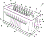
fig. 1 is a perspective view of a cooking system in a first cooking orientation according to an embodiment;
fig. 2 is a perspective view of the cooking system in a first cooking orientation according to an embodiment;
fig. 3 is another perspective view of the cooking system of fig. 2 in a first cooking orientation, according to an embodiment;
fig. 4 is a perspective view of the cooking system in a first cooking orientation according to an embodiment;
fig. 5a is a perspective view of at least one food supporting element when the cooking system is in a first cooking orientation according to an embodiment;
fig. 5b is a perspective view of at least one food supporting element when the cooking system is in a second cooking orientation according to an embodiment;
fig. 6 is a side view of a cooking system including a load/ejector rod according to an embodiment;
fig. 7 is a perspective view of a portion of a support member and a movement mechanism of a cooking system according to an embodiment;
FIG. 8 is a perspective view of a portion of a moving mechanism and a support member of a cooking system according to another embodiment;
FIG. 9 is another perspective view of a portion of the movement mechanism and support member of FIG. 8 according to another embodiment;
fig. 10a is a perspective view of a portion of a moving mechanism and a support member of a cooking system when the support member is in an inactive position according to an embodiment;
FIG. 10b is a perspective view of a portion of the movement mechanism and support member of FIG. 10a when the support member is in an active position, according to an embodiment;
fig. 11a is a cross-sectional view of the cooking system when the support member is in an inactive position according to an embodiment;
fig. 11b is a cross-sectional view of the cooking system of fig. 11a when the support member is in an inactive position, according to an embodiment;
fig. 12a is a cross-sectional view of the cooking system when the support member is in an inactive position according to an embodiment;
fig. 12b is a cross-sectional view of the cooking system of fig. 11a when the support member is in an inactive position, according to an embodiment;
fig. 13a is a perspective view of a portion of a cooking system when a support member is in an inactive position according to an embodiment;
fig. 13b is a perspective view of a portion of the cooking system of fig. 13a when the support member is in an inactive position, according to an embodiment;
fig. 14 is a schematic diagram of a control system of a cooking system according to an embodiment;
fig. 15 is a perspective view of the cooking system of fig. 1 in a second cooking orientation, according to an embodiment;
fig. 16 is a perspective view of the cooking system of fig. 2 in a second cooking orientation, according to an embodiment;
fig. 17 is a perspective view of the cooking system of fig. 2 in a second cooking orientation with accessories located in the interior cooking compartment, according to an embodiment;
fig. 18 is a perspective view of the cooking system of fig. 4 in a second cooking orientation, according to an embodiment;
fig. 19 is a perspective view of the cooking system in a first cooking orientation according to an embodiment;
fig. 20 is a perspective view of the cooking system of fig. 19 in a second cooking orientation, according to an embodiment;
fig. 21 is a schematic view of a pivoting structure of a cooking system according to an embodiment;
fig. 22 is an end view of a cooking system including a movement mechanism according to an embodiment;
fig. 23 is a perspective view of the cooking system in a first cooking orientation according to an embodiment;
fig. 24a is an end view of a mechanism for moving a food supporting element of a cooking system when the cooking system is in a first cooking orientation, according to an embodiment;
fig. 24b is an end view of the mechanism of fig. 24a when the cooking system is in a second cooking orientation, according to an embodiment;
fig. 25a is a perspective view of a mechanism for moving a food supporting element of a cooking system when the cooking system is in a first cooking orientation, according to an embodiment;
fig. 25b is a perspective view of the mechanism of fig. 25a when the cooking system is in a second cooking orientation, according to an embodiment;
fig. 26a is a perspective view of the cooking system in a first cooking orientation according to an embodiment;
fig. 26b is a perspective view of a movement mechanism of the cooking system of fig. 26a, according to an embodiment;
fig. 27a is a perspective view of the cooking system in a first cooking orientation according to an embodiment;
fig. 27b is a perspective view of a movement mechanism of the cooking system of fig. 27a, according to an embodiment;
fig. 28 is a perspective view of a locking mechanism of the cooking system when the cooking system is in a first cooking orientation, under an embodiment;
fig. 29a is an end view of a locking mechanism of a cooking system when the cooking system is in a first cooking orientation, according to an embodiment;
fig. 29b is an end view of the locking mechanism of fig. 29a when the cooking system is in a second cooking orientation, according to an embodiment;
fig. 30 is a side view of the locking mechanism of fig. 29a when the cooking system is in a first cooking orientation, according to an embodiment;
fig. 31 is a perspective view of the cooking system in a second cooking orientation according to an embodiment;
fig. 32 is a detailed perspective view of a portion of the cooking system of fig. 31, according to an embodiment;
fig. 33 is a perspective view of the cooking system in a second cooking orientation according to an embodiment;
fig. 34a is a side view of a portion of the cooking system in a second cooking orientation, according to an embodiment;
fig. 34b is a perspective view of the cooking system of fig. 34a, according to an embodiment;
fig. 35a is a perspective view of an engagement mechanism of a cooking system according to an embodiment;
fig. 35b is a perspective side view of the engagement mechanism of fig. 35a, according to an embodiment;
fig. 36a is a perspective view of an engagement mechanism of a cooking system according to another embodiment;
fig. 36b is a perspective side view of the engagement mechanism of fig. 36a, according to an embodiment;
fig. 37a is a perspective view of an accessory configured for use with a cooking system, according to another embodiment;
FIG. 37b is a perspective side view of an accessory and an engagement mechanism according to an embodiment;
fig. 38a is a perspective view of an accessory configured for use with a cooking system, according to another embodiment;
fig. 38b is a perspective side view of an accessory mounted within a cooking system according to an embodiment;
fig. 39 is a schematic view of the interior of the cooking system in a second cooking orientation, according to an embodiment;
fig. 40 is a perspective view of the cooking system in a second cooking orientation according to an embodiment;
fig. 41a is a perspective view of the cooking system in a first cooking orientation according to an embodiment;
fig. 41b is a perspective view of the cooking system of fig. 41a in a second cooking orientation, according to an embodiment;
fig. 42a is a perspective view of the locking mechanism when the cooking system is in a first cooking orientation, according to an embodiment;
fig. 42b is a perspective view of the locking mechanism of fig. 42a when the cooking system is transitioned between the first and second cooking orientations, according to an embodiment; and
fig. 42c is a perspective view of the locking mechanism of fig. 42a when the cooking system is in the second cooking orientation, under an embodiment.
The detailed description explains embodiments of the disclosure, together with advantages and features, by way of example with reference to the drawings.
Detailed Description
Referring now to fig. 1-4, various examples of a cooking system 20 suitable for use on a support surface 22, such as a countertop, are shown. The cooking system 20 includes an insulated housing 24 having an internal cooking compartment or cooking compartment 26. In the non-limiting embodiment shown, the housing 24 includes a left side 28, a right side 30, a front 32, a rear 34, and a bottom 36 that are connected to one another such that the internal cooking compartment 26 is located therebetween. In an embodiment, the housing 24 additionally includes a top 38 through which the user accesses the cooking compartment 26. However, it should be understood that embodiments in which the housing 24 does not include a top 38 or includes at least a partially movable top 38 (e.g., a door) are also within the scope of the present disclosure.
As shown, the top 38 of the housing 24 may extend between the left and right sides 28, 30, respectively, and between the front and rear portions 32, 34, respectively. In such embodiments, an opening 40 is formed in the top 38 for providing access to the cooking compartment 26 of the housing 24. Although the opening 40 is shown as being exposed to ambient air, it should be understood that embodiments are within the scope of the present disclosure in which the housing 24 additionally includes a door (not shown) or other component that is movable to selectively seal the opening 40 formed in the top 38. Further, the housing 24 is illustrated and described herein as an outer housing of the cooking system 20. Thus, one or more radiant enclosures may be located between the inner surface of the housing 24 and the cooking compartment 26; however, it should be understood that in other embodiments, the housing 24 described herein may alternatively refer to an inner housing disposed in a separate outer housing or shell.
As best shown in fig. 5a, 5b, 11a, 11b, 12b, 13a and 13b, at least one food supporting element 42 is operable to position and retain a food item in the cooking compartment 26. In the non-limiting embodiment shown, the at least one food supporting element 42 includes a first food supporting element 42a positioned within the inner cooking compartment generally adjacent to a first inner surface 46 of the inner cooking compartment 26 and a second food supporting element 42b positioned within the inner cooking compartment generally adjacent to an opposing second inner surface 48 of the inner cooking compartment 26. In an embodiment, the first food supporting element 42a and the second food supporting element 42b cooperate to form a cage. A gap 50 is defined between the first and second food supporting elements 42a, 42b for receiving food items. At least one of the first and second food supporting elements 42a, 42b defines a supporting surface operable to contact a surface of a food item rested within the gap 50. The first and second food supporting elements 42a, 42b may be formed of any suitable thermally conductive material, such as a metal, and more specifically, such as an electrical wire. Further, the configuration of the first and second food supporting elements 42a, 42b may be substantially the same, or may be different. It should be understood that the at least one food supporting element 42 shown and described herein is by way of example only. It is also within the scope of the present disclosure for cooking system 20 to have any number and/or configuration of food support elements disposed within the internal cooking compartment 26, such as a single food support element or more than two food support elements.
In an embodiment, a support bar or support member 52 (see fig. 8 and 11a-13a) is also disposed within the cooking compartment 26 and is configured to support the food product against gravity. As shown, for example, the support member 52 may extend across the inner cooking compartment 26 between the left side 28 and the right side 30, and may additionally span the gap 50 defined between the first and second food supporting elements 42a, 42 b. In an embodiment, the support member 52 includes a plurality of teeth 54 that extend in opposite directions toward the first and second food supporting elements 42a and 42b, respectively. Although the teeth 54 are shown as angled upwardly in a direction toward the opening 40, embodiments are also contemplated herein in which one or more of the teeth 54 have a generally horizontal configuration. Further, the opposing teeth 54 may be generally aligned, or may be offset from one another. It should be understood that the support members 52 shown and described herein are by way of example only, and that support members 52 having another configuration (e.g., formed from a rectangular piece of material (see fig. 7)) are also within the scope of the present disclosure.
The movement mechanism 56 may be used to move the support member 52 within the cooking compartment 26 between an inactive position (see fig. 11a, 12a, and 13a), for example, near the opening 40, and an active position (see fig. 11b, 12b, and 13b), for example, near the bottom 36 of the housing 24. The transition of the support member 52 from the inactive position to the active position is configured to position a quantity of food product within the cooking compartment 26 in the gap 50 defined between the food support elements 42. Further, in some embodiments, the movement mechanism 56 may be operable to transition the support member 52 from the active position to the inactive position to substantially remove the food item from the cooking compartment 26. The distance between the support member 52 and the opening 40 is greater when the support member is in the active position than when the support member 52 is in the inactive position. In an embodiment, a biasing mechanism 57 (see fig. 13a and 13b) is coupled to the support member 52 and configured to bias the support member 52 toward the inactive position.
In an embodiment, a user may manually translate the support member 52 within the cooking compartment 26 via the movement mechanism 56. An example of such a manual moving mechanism 56 is a load/push-out lever. As shown in fig. 6 and 7, the rod is movable relative to the housing 24, for example translatable within slots 58 formed at respective sides of the housing 24. In the non-limiting embodiment shown, a first portion of the lever 56 is directly or indirectly connected to the support member 52, and another portion of the lever 56, such as a paddle 60, is disposed adjacent an exterior of the housing 24 and forms a user interface of the movement mechanism 56. The rod 56 additionally includes a bar 62 oriented parallel to the slot 58. The bar 62 defines an axis of translation of the rod 56. Although the strips 62 are shown as extending generally vertically between the bottom 36 and top 38 of the shell 24, embodiments are also contemplated herein in which the strips 62 are oriented at an angle to the shell. To operate the movement mechanism 56, the user applies a force to the paddle 60 to manually move the lever 56, and thus the support member 52, from the inactive position to the active position.
Referring now to fig. 8-10b, in an alternative embodiment, the movement mechanism 56 is configured to automatically move the support member 52 between the inactive position and the active position in response to a user input. In such embodiments, the movement mechanism 56 may include a motor or other actuation device 64 operably coupled to the support member 52. As shown, the movement mechanism 56 may additionally include a sliding element 66 connected to the support member 52 and configured to translate vertically along the one or more bars 62. In the non-limiting embodiment shown, a connecting member 68 extending from the motor 64 is coupled to the sliding element 66. In addition, an input 70 (e.g., a button) configured to operate the motor 64 is located on the exterior of the housing 24 to facilitate access by a user. In response to a user applying a force to the input 70, the motor 64 will rotate the connecting member 68, which in turn translates the sliding element 66 and the support member 52 along the axis defined by the at least one bar 62. The motor 64 may be bi-directional such that the support member 52 may be automatically lowered (fig. 10a) and raised (fig. 10b) by the movement mechanism 56 in response to the input 70. The motor 64 may additionally operate in response to commands generated by a processor of the cooking system 20, for example, indicating when a cooking operation is complete. The connection defined between the motor 64 and the support member 52 shown and described herein is intended to be exemplary only, and it should be understood that any suitable configuration of the movement mechanism 56 capable of automatically moving the support member 52 within the cooking compartment 26 is also contemplated herein. Moreover, embodiments of any type of connection between the motor 64 and the support member 52 (including the motor or actuation device 64 being configured to translate rather than rotate) are within the scope of the present disclosure.
At least one biasing mechanism may be operably coupled to one or more of the first and second food supporting elements 42a, 42 b. In the non-limiting embodiment shown, the same biasing mechanism 57 (fig. 13a and 13b) coupled to support member 52 is also coupled to first and second food support elements 42a and 42 b. The biasing force of the at least one biasing mechanism 57 defines a neutral position of the first and second food supporting elements 42a, 42b and, thus, defines a neutral gap 50 between the first and second food supporting elements 42a, 42 b. Accordingly, the first and second food supporting elements 42a, 42b may be configured to further separate, thereby increasing the gap 50 to accommodate food items larger than the intermediate gap 50. Upon removal of such food, the biasing force of the at least one biasing mechanism 57 will return the first and second food supporting elements 42a, 42b to the neutral position.
In an embodiment, the gap 50 defined between the first and second food support elements 42a, 42b is configured to change in response to movement of the support member 52 within the cooking compartment 26. For example, when the support member 52 is in the inactive position (fig. 11a, 12a and 13a), the intermediate gap 50 is substantially uniform throughout the height of the first and second food supporting elements 42a and 42 b. In an embodiment, the mid-gap 50 is about 35 mm. When the support member 52 is lowered to the active position (fig. 11b, 12b, and 13b), at least one of the first and second food supporting elements 42a, 42b is moved to reduce the gap 50 and limit movement of food items located between the first and second food supporting elements 42a, 42 b.
In an embodiment, first and second food supporting elements 42a, 42b are configured to rotate about an axis in response to support member 52 moving to the active position. As a result of this rotation, the gap 50 varies across the height of the first and second food supporting elements 42a, 42b (best shown in fig. 12 b). In an embodiment, the ends of the first and second food supporting elements 42a, 42b closest to the opening 40 are configured to rotate inward. In such embodiments, the narrowest portion of the gap 50 defined between the first and second food support elements 42a, 42b (and no food items within the gap 50) may be about 5 mm. In other embodiments, one or more of the first and second food supporting elements 42a, 42b may be configured to translate horizontally in response to the support member 52 moving to the active position (fig. 11 b).
This movement of at least one of the first and second food supporting elements 42a, 42b may be driven by the support member 52. In the non-limiting embodiment shown, the struts or other elongated members 72 associated with the corresponding food support elements 42 are positioned within one or more slots or openings 74 formed in a portion of the panel or radiant enclosure (identified at 76 in fig. 11a-13 b) adjacent one side of the cooking compartment 26. At least one post 72 may be integrally formed with first and second food supporting elements 42a, 42b or may be part of a separate component that is connected to first and second food supporting elements 42a, 42 b.
The at least one opening 74 may have any suitable configuration, such as a horizontal configuration, an angled configuration, or an arched configuration. The configuration of the opening 74 at least partially defines the movement of the food supporting member 42 associated therewith. In the non-limiting embodiment shown, each of the first and second food supporting elements 42a, 42b has at least one post 72, such as two posts, associated therewith. However, any suitable number of struts 72 and openings 74 is also contemplated herein, including a single strut and opening, or more than two struts and openings. In such embodiments, the first and second food supporting elements 42a, 42b may include upper and lower struts that are received within corresponding elongated openings.
One or more of the posts 72 are configured to translate within the respective openings 74 as the support member 52 moves between the inactive position and the active position. In the illustrated non-limiting embodiment of fig. 11a and 11b, the openings 74 associated with the upper and lower struts 72 have a generally horizontal orientation and are parallel to each other. Further, as shown, the openings 74 associated with the upper and lower struts 72 of each of the first and second food supporting elements 42a, 42b are of equal length. Upon movement of the support member 52 to the active position, the biasing force of the biasing mechanism translates the post 72 within the opening 74. Because each post 72 is configured to move the same distance in response to the biasing force of the biasing mechanism, the first and second food supporting elements 42a, 42b are oriented substantially parallel when the support member 52 is in both the inactive and active positions. In such embodiments, when the support member 52 is in the inactive and active positions, the gap 50 is substantially constant over the entire height of the first and second food supporting elements 42a, 42 b.
In embodiments where at least one of the first and second food supporting elements 42a, 42b is configured to rotate in response to movement of the support member 52, rotation of the first and second food supporting elements 42a, 42b may occur due to movement of some, but not all, of the struts associated with each of the first and second food supporting elements 42a, 42 b. In the non-limiting embodiment of fig. 12a-12b, the securing pin 75 is disposed adjacent an end, such as the end closest to the bottom 36 of the housing 24, for example, of each of the first and second food supporting elements 42a, 42 b. Further, the plurality of openings 74 are arcuate in shape. Because the lower end of each of first and second food supporting elements 42a, 42b is restrained from outward movement by pin 75, the biasing force applied by biasing mechanism 57 to first and second food supporting elements 42a, 42b causes the upper end of each of first and second food supporting elements 42a, 42b to rotate inward while the lower end of each of first and second food supporting elements 42a, 42b remains stationary when the support member is in the active position.
In another embodiment shown in fig. 13a and 13b, the first and second food supporting elements 42a and 42b are configured to translate and pivot within the internal cooking compartment 26 in response to the support member 52 moving to the active position. As shown, each opening 74 has a generally horizontal configuration. However, the length of the opening 74 that receives and defines the path of travel of the upper strut 72 is greater than the length of the opening 74 that receives and defines the path of travel of the lower strut 72. Thus, when support member 52 is lowered to the active position, biasing mechanism 57 will translate first and second food support elements 42a, 42b in a substantially parallel configuration until lower struts 72 abut the ends of their respective openings 74. While further movement of the lower strut is prevented, the biasing force of the biasing mechanism will cause the upper strut 72 to continue to translate within the opening 74. This additional movement of the upper support post 72 pivots the first and second food supporting elements 42a, 42 b. In embodiments where the first and second food support elements 42a, 42b are configured to translate and pivot, the gap 50 when the support member 52 is in the active position is not uniform throughout the height of the first and second food support elements 42a, 42 b. In addition, the gaps 50 adjacent the upper and lower ends of the first and second food supporting elements 42a, 42b when the support member 52 is in the active position are less than the gaps 50 adjacent the upper and lower ends of the first and second food supporting elements 42a, 42b when the support member 52 is in the inactive position.
The inner cooking compartment 26 is heated by at least one heating element. With continued reference to fig. 11a-13b, in the illustrated non-limiting embodiment, the cooking system 20 includes one or more first heating elements 78 positioned within the cooking compartment 26, e.g., adjacent the rear 34 of the housing 24. In the non-limiting embodiment shown, the cooking system 20 includes a plurality of first heating elements 78, for example three first heating elements, that are horizontally oriented and generally parallel to the front and rear portions 32, 34 and are spaced apart throughout the height of the cooking compartment 26. It should be understood that any number and configuration of first heating elements 78 are contemplated herein.
Alternatively or additionally, at least one second heating element 80 may be positioned within the cooking compartment 26, such as adjacent the front 32 of the housing 24. In the non-limiting embodiment shown, the cooking system 20 includes a plurality of second heating elements 80, for example three second heating elements, oriented generally parallel to the front 32 and rear 34 and spaced apart across the height of the cooking compartment 26. The first heating element 78 and the second heating element 80 may be substantially aligned, or may be staggered with respect to each other.
It should be understood that although the first and second heating elements 78, 80 of the cooking system 20 are shown and described as being positioned within the interior cooking compartment 26 generally adjacent to the front 32 and rear 34 of the housing 24, embodiments are also contemplated herein wherein the cooking system 20 alternatively or additionally includes one or more heating elements (not shown) located within the cooking compartment adjacent to the left side 28, right side 30, or bottom 36 of the housing or within the center of the cooking compartment 26. Further, embodiments in which one or more of the first heating element 78 and the second heating element 80 extend vertically between the top portion 38 and the bottom portion 36 are also within the scope of the present disclosure. It should also be understood that the cooking compartment 26 may alternatively or additionally be heated by one or more heating elements (not shown) located remotely from the cooking compartment 26.
The one or more first and second heating elements 78, 80 of the cooking system 20 may be selected to perform any suitable type of heating, including but not limited to conduction, convection, radiation, and induction. Further, the heat output on one or more of the first heating element 78 and the second heating element 80 may vary. In an embodiment, one or more of the first and second heating elements 78, 80 have a non-uniform configuration, e.g., comprising coiled wires disposed within a tube that heat and emit radiation when power is supplied thereto. By varying the spacing between adjacent coils over the length of the first heating element 78 and the second heating element 80, greater heat may be emitted at various portions of the first heating element 78 and the second heating element 80 than at other portions. However, embodiments in which the heat output by one or more of the first heating element 78 and the second heating element 80 is constant over the length of the heating elements are also within the scope of the present disclosure.
A control panel or user interface 82 for operating the cooking system 20 may be mounted to an exterior portion of the housing 24, such as the top 38 (see fig. 1, 15, 25a, 25b, 26a, 27a, 31, 34b, and 40). Alternatively, as best shown in fig. 4 and 18, the cooking system 20 may include a component 84 movably mounted to the housing 24, and at least a portion of the control panel 82 may be coupled to or integrated into the movable component 84. In an embodiment, the movable member 84 is a handle pivotally mounted to opposite sides of the housing 24, such as the left side 28 and the right side 30.
The control panel 82 is part of a control system 86 that is electrically connected to the one or more first and second heating elements 78, 80. A schematic diagram of control system 86 is shown in fig. 14. The control panel 82 includes one or more inputs 88 associated with energizing or operating one or more of the first and second heating elements 78, 80 of the cooking system 20 and for selecting various operating modes of the cooking system 20. One or more of the inputs 88 may include a light or other indicator showing the user that the respective input 88 has been selected. The control panel 82 may additionally include a display 90 separate from and associated with the at least one input 88. However, embodiments are also contemplated herein in which the display 90 is integrated with the at least one input 88.
The operation of the one or more inputs 88 will be described in more detail below. As shown in fig. 14, the control system 86 includes a controller or processor, shown schematically at 92, for controlling the operation of the first and second heating elements 78, 80 in response to user input provided through one or more inputs 88 and for executing a stored sequence of heating operations using an algorithm. In embodiments where the cooking system 20 includes multiple heating elements, the first heating element 78 and the second heating element 80 may be independently operable. Further, the heating output of one or more of the first heating element 78 and the second heating element 80 may be varied in response to the power supplied to the first heating element 78 and the second heating element 80. Control system 86 may include one or more sensors arranged in communication with processor 92 and operable to monitor one or more parameters of cooking system 20, such as the temperature within cooking compartment 26. In some embodiments, the cooking system may additionally include an air moving device, such as a fan, to move fluid through the cooking compartment 26 to enable convection operation. In such embodiments, the air moving device is operably coupled to and controlled by the processor 92.
In an embodiment, at least one input 88 on control panel 82 is an on/off button that allows a user to activate or deactivate control panel 82. When the control panel 82 is deactivated, neither the first heating element 78 nor the second heating element 80 is energized. In an embodiment, the at least one input 88 is operable to select one or more manual operating modes of at least one of the first and second heating elements 78, 80. Alternatively or additionally, the at least one input 88 is operable to select a stored operational sequence of the at least one first and second heating elements 78, 80. In some cases, the stored sequences may be particularly well-suited for a given food preparation method and/or for a particular ingredient or type of ingredient. The plurality of stored sequences associated with the at least one input 88 may be stored in a memory accessible by the processor 92. Alternatively, the plurality of stored sequences may be stored remotely from the cooking system 20 and may be accessed by the processor 92, for example, by wireless communication or the like.
In addition, the user is able to input or select a time associated with operation of the cooking system 20 in a desired manual mode. The time may be entered through the same input 88 or different inputs 88 as used to select the mode of operation. Further, in embodiments where cooking system 20 is in a mode configured to execute a stored sequence in response to selecting one of the inputs, display 90 may indicate the time remaining. Temperature or other parameters, such as baking color, etc., may also be input via input 88.
The at least one input 88 may include a different start button intended to initiate operation in a desired mode, a different stop button to stop full operation, or a stop/start button intended to initiate and stop functions. Alternatively, cooking system 20 may be operable to automatically begin operation after a predetermined time has elapsed after the input has been selected and any necessary information has been provided to control panel 82. One or more of the other inputs 88, such as knobs, etc., may be operated, for example, by pushing the knobs toward control panel 82 to start and stop operation of cooking system 20, whether cooking system 20 follows a stored sequence or is in manual mode.
The one or more inputs 88 are operable to initiate operation of the cooking system 20 in a plurality of cooking modes. Examples of modes of operation of cooking system 20 include, but are not limited to, baking, grilling, warming, and reheating. The independent control of the first and second heating elements 78, 80 allows a user to configure the cooking/heating cycle based on the type of food product positioned within the cooking compartment 26.
In an embodiment, the cooking system 20 is changeable between a first orientation or configuration (fig. 1-4 and 19) and a second orientation or configuration (fig. 15-18 and 20). It should be understood, however, that cooking system 20 may perform cooking operations in a first orientation or in a second orientation or may be inoperative or "stowed". In the non-limiting embodiment shown, the housing 24 of the cooking system 20 is rotatable about a pivot axis S between a first orientation and a second orientation. In the first orientation, the housing 24 and cooking compartment 26 have a generally vertical orientation, similar to a conventional oven. Accordingly, the first heating element 78 and the second heating element 80 of the cooking system 20 have a first orientation, e.g., are vertically spaced apart. As shown, in a first orientation, at least one of the top 38 and the bottom 36 of the housing 24, including the opening 40 formed therein, is arranged substantially parallel to the support surface 22 on which the cooking system 20 is located and the front portion 32 is oriented substantially perpendicular to the support surface 22.
The housing 24 of the cooking system 20 is rotatable about the pivot axis S from the second orientation toward the first orientation in a second direction indicated by arrow B (see fig. 24B, 25B). As cooking system 20 is transitioned between the first orientation and the second orientation, top 38 and/or opening 40 are rotated out of plane, such as from a first plane to a second plane different from the first plane. Because the surface area of the housing 24 projected onto the support surface 22 when in the first orientation is substantially less than the surface area of the housing 24 projected onto the support surface 22 when in the second orientation, the surface area of the support surface 22 occupied by the cooking system 20 is minimized when the cooking system 20 is in the first orientation.
In an embodiment, the pivot axis S is positioned near an edge of the housing 24. For example, the pivot axis S is shown located near a bottom corner of the housing 24, near the interface between the bottom 36 and the front portion 32, or near the interface between the bottom 36 and the rear portion 34. However, it should be understood that embodiments are also contemplated herein in which the pivot axis S is disposed along another edge of the housing 24, such as adjacent to the interface between the bottom and the left and right sides 28, 30.
The pivot axis S may be defined by a pivot structure 94 that is coupled to or integrally formed with the housing 24. Thus, the pivot structure 94 positions at least a portion of the housing 24 relative to the support surface 22. In the illustrated non-limiting embodiment of fig. 2-3, 16 and 17, the pivot structure 94 comprises a component that is rotatably attached to the bottom 36 of the housing 24. When cooking system 20 is in the first orientation, main body 96 of pivot structure 94 is disposed between bottom 36 of housing 24 and support surface 22, while when cooking system 20 is rotated about pivot axis S to the second orientation, cooking system 20 may be supported by pivot structure 94 in a cantilevered configuration. However, in other embodiments, one or more legs (not shown) may extend from a portion of the housing 24, such as from the front 32 of the housing 24. These feet may cooperate with the pivot structure 94 to position the cooking system 20 on the support surface 22 in either the first or second orientation.
In another embodiment, best shown in fig. 1, 6, 15, 19-21, the pivot structure 94 includes one or more mounting brackets 98 coupled to the housing 24. In the non-limiting embodiment shown, the pivot structure 94 includes two separate mounting brackets 98 disposed, for example, at the left side 28 and the right side 30 of the housing 24. However, embodiments that include a single mounting bracket 98 extending between opposite sides of the housing 24 or two mounting brackets 98 integrally formed or connected together are also within the scope of the present disclosure. One or more mounting brackets 98 are pivotally connected to the housing 24 to position the cooking system 20 on the support surface 22. Thus, as the housing 24 rotates relative to the at least one mounting bracket 98, the one or more mounting brackets 98 remain constant or fixed relative to the support surface 22. As shown, the housing 24 may be supported entirely by the at least one mounting bracket 98, e.g., in a cantilevered configuration, in both the first and second orientations.
In the embodiment best shown in fig. 21, each mounting bracket 98 includes a pin connector 100 receivable within a corresponding opening 102 formed in one side (e.g., left side 28 and right side 30) of housing 24. In the non-limiting embodiment shown, the pin connectors 100 of at least one mounting bracket 98 are each coaxially oriented. The pin connectors 100 cooperate together to define a pivot axis S. The pin connector 100 may directly contact the inner surface of the opening 102, or a bearing (not shown) may be located at the interface between the pin connector 100 and the opening 102 to facilitate movement of the housing 24 relative to the pin connector 100. In embodiments, the pin connector 100 and/or the opening 102 may be configured to limit rotation of the housing 24 about the pivot axis S to a position beyond the first orientation and the second orientation. However, rotation of the housing 24 about the pivot axis S may be controlled or limited by any suitable mechanism.
In yet another embodiment, the pivot structure 94 may be a rounded feature (not shown) disposed at an edge of the housing 24. However, the rounded features of the pivot structure 94 are different than the rounded edges of the housing 24. In an embodiment, the pivot structure 94 includes one or more arcuate features, such as ribs or the like, located on an outer surface of the housing 24 and extending between the base 36 and the rear 34. The origin of each arcuate feature may define a pivot axis S, and the profile of the arcuate feature may assist a user in rotating the housing 24 between the first and second positions. It should be understood that the various embodiments of the pivot structure 94 shown and described herein are by way of example only, and that any suitable configuration that allows the housing 24 to be transitioned between the first and second orientations relative to the support surface 22 is within the scope of the present disclosure. Although the housing 24 is rotatable relative to the pivot structure 94 as described herein, it should be understood that embodiments in which the pivot structure is rotatable relative to the housing 24 are also contemplated herein.
To use cooking system 20 in the first orientation, a food item is inserted into a portion of gap 50 between first and second food support elements 42a and 42 b. In the first orientation, first food supporting element 42a defines a first supporting surface configured to contact a first side or surface of a food item being rested within gap 50, and second food supporting element 42b defines a second supporting surface operable to contact a second opposing surface of the food item being rested within gap 50. One end of the food item is typically arranged to contact and be supported by the support member 52 against gravity. To properly position the food product within the gap 50 for a cooking operation, the support member 52 is translated from the raised, inactive position to the lowered, active position by operating the movement mechanism 56. When the food items are properly positioned within the gap 50, a majority, or in some embodiments all, of the food items are positioned within the cooking compartment 26 between the first and second food supporting elements 42a, 42b, adjacent to the one or more first and second heating elements 78, 80.
In an embodiment, operation of the movement mechanism 56 and/or translation of the support member 52 to the active position automatically initiates the first cooking operation when the cooking system 20 is in the first orientation. For example, when the support member 52, or the movement mechanism 56 associated therewith, is moved to the active position, a signal may be generated and communicated to the processor 92 to energize one or more of the plurality of first and second heating elements 78, 80 and/or a timer. In an embodiment, operation of the moving mechanism 56, such as moving a lever to a lowered position, operates a switch (not shown), thereby completing a circuit for delivering power to one or more components of the cooking system 20.
Referring now to fig. 22, an electromagnetic trap 104 operably coupled to the processor 92 may be positioned adjacent a portion of the support member 52 or an end of the slot 58. When energized, the magnetic field generated by the electromagnetic trap 104 may cooperate with a portion of the movement mechanism 56 to hold the movement mechanism 56 and/or the support member 52 in the lowered position. In an embodiment, the attraction between the movement mechanism 56 and/or a portion of the support member 52 and the electromagnetic trap 104 is sufficient to counter the biasing force of the biasing mechanism 57 on the movement mechanism 56.
With continued reference to fig. 22, in an embodiment, where the movement mechanism 56 is a manually translatable lever, the paddle 60 includes a first portion 106 and a second portion 108. The first portion 106 and the second portion 108 are removably connected to each other by any suitable coupling mechanism 109, including but not limited to, for example, magnets. In such embodiments, support member 52 may be associated with or connected to first portion 106 of paddle 60. To initiate the first cooking operation, the first portion 106 and the second portion 108 are each moved from the inactive position to the active position as a single unit. In the active position, second portion 108 of paddle 60 engages the switch. Additionally, electromagnetic trap 104 may be configured to cooperate with second portion 108 to retain second portion 108 in the lowered position, as previously described.
During a first cooking operation, first portion 106 of paddle 60 may be selectively decoupled from second portion 108, for example, by applying a force thereto. When the first portion 106 is decoupled from the second portion 108, the support member 52 connected to the first portion 106 can be translated within the slot 58 to a raised position, thereby moving at least a portion of the food product within the gap 50 out of the cooking compartment 26. In this raised position, the user may view the food product to determine its cooking state, such as food product color or doneness, without interrupting the first cooking operation. However, it should be understood that it is within the scope of the present disclosure to have only a single piece paddle 60 that is translatable relative to slot 58.
As previously described, cooking system 20 is operable to perform a second cooking operation when cooking system 20 is in a second orientation. Examples of the second cooking operation include, but are not limited to, baking, grilling, heating, warming, reheating, and the like. Depending on the second cooking operation selected to be performed, all or a portion of the first and second heating elements 78, 80 of the cooking system 20 are energized. For example, one or more of the plurality of first heating elements 78 may be energized, one or more of the plurality of second heating elements 80 may be energized, or at least one of the plurality of first heating elements 78 and the plurality of second heating elements 80 may be energized.
When the cooking system 20 is transitioned between the first orientation and the second orientation, the at least one first food supporting element 42a and second food supporting element 42b are configured to move between a first position (see fig. 5a and 41a) and a second position (see fig. 5b and 41 b). When the cooking system 20 is in the first cooking orientation, the at least one first and second food support elements 42a, 42b are disposed in a first extended position relative to the cooking compartment 26. For example, a first food supporting element 42a is offset a distance from the first inner surface 46, and a second food supporting element 42b is also offset a distance from the second inner surface 48. The distance between each of the first and second food supporting elements 42a, 42b and the respective first and second inner surfaces 46, 48 may be, but need not be, the same.
When the cooking system 20 is transitioned to the second orientation, the at least one food support element 42 is moved to a second retracted position relative to the inner cooking compartment 26. Accordingly, the distance defined between first inner surface 46 and first food supporting element 42a and/or the distance between second inner surface 48 and second food supporting element 42b is reduced when cooking system 20 is in the second orientation as compared to when cooking system 20 is in the first orientation. Accordingly, a gap 50 defined between first and second food support elements 42a, 42b is greater when cooking system 20 is in the second orientation than when cooking system 20 is in the first orientation (whether support member 52 is in the active or inactive position). In an embodiment, the gap 50 between the first food supporting element 42a and the second food supporting element 42b in the first extended position is about 35mm, and the gap 50 between the first food supporting element 42a and the second food supporting element 42b in the second retracted position is about 72 mm.
By increasing the gap 50 when the cooking system 20 is in the second orientation, larger food products may be received within the cooking compartment 26. Thus, a food product having one or more topping ingredients located thereon, such as a piece of bread on which a slice of cheese is stacked, may be inserted into cooking compartment 26 without interfering with the adjacent food supporting element 42. A second food support element 42b disposed adjacent the front 32 of the housing 24 may be used to support food items within the cooking compartment 26 when the housing 24 is in the second orientation. For example, the second food supporting element 42b may directly support the food item such that the food item is placed on or in contact with the second food supporting element 42 b. Alternatively or additionally, the second food support element 42b may indirectly support the food item such that the accessory or insert is positioned between the second food support element 42b and the food item to be cooked. Thus, the first food supporting element 42a may simply provide a barrier to prevent direct contact with one or more adjacent heating elements 78.
In the illustrated non-limiting embodiment as illustrated, the opening 74 has a generally arcuate profile; however, it is within the scope of the present disclosure for opening 74 to have any suitable shape. For example, the opening 74 of the mechanism 110 shown in fig. 25a-25b has a generally linear or horizontal configuration. As previously described, the opening 74 defines a path of movement of the post 72, and thus the first and second food supporting elements 42a, 42b, within the cooking compartment 26. For example, when first and second food supporting members 42a, 42b are in the extended position, post 72 of first and second food supporting members 42a, 42b is disposed at a first location within each opening 74, e.g., adjacent a first end of the opening. Similarly, when the first and second food supporting members 42a, 42b are in the retracted position, the post 72 is in a second position within the opening 74, such as adjacent a second opposite end of the opening.
In the illustrated non-limiting embodiment of fig. 24a and 24b, the center support bar 112 is mounted to a surface of the panel or radiant housing and extends parallel to the gap 50. The support wedges 114 are slidably mounted to the support bar 112. A mount 116 disposed within the interior of the shell 24 and secured to the pivot structure 94 is connected to the support wedge 114 by a connecting member 118, such as a bar. In an embodiment, when cooking system 20 is in the first orientation, supporting wedges 114 do not engage or interact with struts 72 associated with first and second food supporting elements 42a, 42b in the extended position in the first position.
In the embodiment of the mechanism 110 shown in fig. 25a and 25b, the mechanism 110 includes a cam plate 120 instead of supporting the wedge 114. The cam plate 120 additionally includes a plurality of slots 122 formed therein, and at least a portion of the posts 72 (e.g., the lower posts) extend through the openings 74 and the slots 122. As shown, the slots 122 of the cam plate 120 have a different configuration than the adjacent openings 74, such as an angled configuration corresponding to the wedge-shaped surface 126 of the cam plate 120. Similar to the support wedges 114, when the cam plate 120 is in the first position, the first and second food support elements 42a, 42b can be shifted between positions associated with the support members 52 in the inactive and active positions. In an embodiment, one or more protrusions 124 extending from the cam plate 120 define a stop position for the first and second food supporting elements 42a, 42b in a direction opposite the bias of the biasing mechanism 57 when the support member 52 is in the inactive position.
The mount 116 remains fixed as the housing 24 of the cooking system 20 rotates about the pivot axis S from the first orientation to the second orientation. Thus, the connecting members 118 coupling the mount 116 to the support wedge 114 or the cam plate 120 apply a force to the support wedge 114 or the cam plate 120 to cause the support wedge 114 or the cam plate 120 to translate laterally along the axis defined by the support bar 112. In an embodiment, the support wedges 114 or the cam plate 120 are configured to translate approximately 20mm in response to rotation of the housing 24 of the cooking system 20 about the pivot axis S.
With respect to the embodiment of the mechanism 110 that includes the support wedges 114 (fig. 23-24b), the engagement between at least one wedge surface 126 of the support wedges 114 and the post 72 exerts an outward force on the post 72. In response to this force, the posts 72 move within the paths defined by the respective openings 74, thereby shifting the first and second food supporting members 42a, 42b to the retracted positions. In the embodiment of the mechanism 110 that includes the cam plate 120 (fig. 25a and 25b), the wedge surface 126 thereof is configured to exert an outward force on the upper strut 72 as the cam plate 120 translates. Due to the configuration of the slots 122, each lower strut 72 is configured to translate outwardly.
Upon rotating the housing 24 back to the first orientation, the one or more wedge surfaces 126 will remove engagement with the post 72. Upon removal of the force from the strut 72, the first and second food supporting elements 42a, 42b may be configured to return to the extended position within the cooking compartment 26 via gravity. However, in other embodiments, a biasing mechanism (not shown) may facilitate movement of the first and second food supporting elements 42a, 42b back to the extended position.
In another embodiment, a movement mechanism 56 associated with support member 52 is also operable to move at least one food supporting element 42 between an extended position and a retracted position. In such embodiments, the movement mechanism 56 may be configured to move the at least one food supporting element 42 prior to rotating the cooking system 20. In such embodiments, the moving mechanism 56 is a manually operable mechanism, such as a lever as previously described. Referring to fig. 26a-27b, during operation in the first cooking mode, a lever portion of, for example, paddle 60 disposed adjacent an exterior of housing 24 has a first configuration. In the non-limiting embodiment shown, the open cam 128 is connected to the lever 56, for example at a location within the housing 24, outside the cooking compartment 26. In addition, at least one slide 130 is mounted to the post 72 extending from the first and second food supporting members 42a, 42b, generally adjacent the opening cam 128. The slide plate 130 is configured to move with the post 72 relative to the at least one slot or opening 74.
The paddle 60 or portion of the user accessible lever 56 is configured to rotate about an axis before the housing 24 is transitioned to the second configuration. In an embodiment, paddle 60 is configured to rotate approximately 90 degrees between a substantially horizontal orientation associated with the extended position of first and second food supporting members 42a, 42b and a vertical orientation associated with the retracted position of first and second food supporting members 42a, 42 b. In an embodiment, when paddle 60 is in a generally horizontal configuration, open cam 128 has a generally vertical orientation and is not in contact with one or more slides 130, and when paddle 60 is in a generally vertical orientation, open cam 128 has a generally horizontal orientation. As paddle 60 rotates about its axis, opening cam 128 rotates into contact with one or more slides 130. The force applied to slide 130 by opening cam 128 causes slide 130, and thus brace 72 and the first and second food supporting members 42a and 42b connected thereto, to transition from the extended position to the retracted position.
A slider 138 or another component may be connected to and/or extend from the rod 56. Thus, the slider 138 is configured to translate with the rod 56 relative to the slot 58. When the rod 56 is in the lowered position, the actuator 134 applying force to the locking mechanism 132 will extend the shaft 136 into the opening formed in the slider 138. The engagement between the shaft 136 and the slider 138 limits movement of the rod 56 from the lowered position. After engagement, the housing 24 may be transitioned from the first orientation to the second orientation. Additionally, in embodiments, when the locking mechanism 132 is active, such as when the shaft 136 is engaged with the slider 138, the locking mechanism 132 prevents engagement of a switch associated with the rod 56 despite the rod 56 being in the lowered position. This prevents power from being delivered to the first and second heating elements 78, 80 before a user initiates a cooking operation. After the housing 24 is transitioned to the second orientation, a second switch (not shown) is activated, thereby allowing power to be delivered to the first and second heating elements 78, 80 to perform a second cooking operation. Further, the locking mechanism 132 may be designed to limit the operation of the actuator 134. For example, in an embodiment, the actuator 134 may only operate when the cooking system 20 is in the first orientation to prevent inadvertent decoupling of the slider 138 and the actuator 134.
Another example of a locking mechanism 132 for a cooking system is shown in FIGS. 42 a-42 c. As shown, the locking mechanism 132 includes a locking member 170 mounted to a portion of the pivot structure 94, for example, within the housing 24. The locking member 170 includes, for example, a locking feature 172, such as a protrusion, extending outwardly therefrom. In the non-limiting embodiment shown, the locking feature 172 extends upwardly, substantially parallel to the movement of the rod 56 when the housing 24 is in the first orientation. Similar to the embodiment of fig. 28-30, a slider 138 or other component may be connected to and/or extend from the rod 56. Accordingly, the slider 138 is configured to translate with the rod 56 relative to the slot 58 and the one or more bars 62. As best shown in fig. 42b, an engagement feature 174, such as a spring-biased strut, extends from the slider 138 in the direction of the locking member 170. Although the engagement feature 174 is shown as extending generally perpendicular to the translation axis of the slider 138, embodiments are contemplated herein in which the engagement feature 174 has another orientation.
The locking feature 172 is axially aligned with the engagement feature 174 of the slider 138. Further, the surface 176 of the locking feature 172 may have a first configuration and the surface 178 of the engagement feature 174 may have a second configuration that is complementary to the first configuration. In the non-limiting embodiment shown, the surface 176 of the locking feature 172 and the surface 178 of the engagement feature 174 are arranged at corresponding angles.
In operation, relative rotation between the housing 24 and the pivot structure 94 occurs. Thus, the locking member 170 rotates relative to the lever 56. In the rotational position, the locking member 170 extends towards the slider 138. As the rod 56 moves downward toward the active position of the support member 52, the engagement feature 174 extending from the slider 138 contacts the locking feature 172. As shown, the angled surface 178 of the engagement feature 174 abuts the similarly angled surface 176 of the locking feature 172. As the slider 138 continues to move downward, the engagement over the angled surfaces 176, 178 applies a force to the engagement feature 174 in a direction opposite the biasing force of the biasing mechanism (not shown) connected thereto. This force retracts the engagement feature 174 inwardly toward the slider 138, allowing the slider 138 to move to a position beyond the locking feature 172, such as vertically below the locking feature. Once the engagement feature 174 is out of contact with the locking feature 172, the biasing force returns the engagement feature 174 to the extended position. Engagement between the other surface of the locking feature 172 and the other surface of the engagement feature 174 retains the slider 138, and thus the rod 56 and the support member 52, in the active position. To release the slider 138, the pivot structure 94 is rotated in a second, opposite direction about the pivot axis S, thereby moving the locking feature 172 out of the path of the engagement feature 174.
One or more cooking accessories or inserts 140 configured to support food items may be mounted within the cooking compartment 26 when the cooking system 20 is in the second orientation. In an embodiment, best shown in fig. 1-3 and 15-18, one or more cooking accessories 140, such as a tray, may be stowed within a cavity or recess 142 formed in or associated with a side of the housing 24 (e.g., the rear 34 of the housing 24). When positioned within cavity 142, a portion of accessory 140 may, but need not, be flush with the outer surface of housing 24. Each of the one or more cooking accessories 140 suitable for use with the cooking system 20 may be supported directly or indirectly within the cooking compartment 26 by the second food support element 42 b.
Referring to fig. 31-37b, cooking system 20 may additionally include an engagement mechanism configured to limit movement of accessory 140 in at least one direction within cooking compartment 26 and indicate to a user when the accessory is at an end of its path of movement. The engagement mechanism may, but need not, be located within the inner cooking compartment 26. Referring now to fig. 32 and 33, in an embodiment, the engagement mechanism is a support feature 144, for example, located near the bottom of the cooking compartment 26 adjacent the second food support element 42b when the cooking system 20 is in the second horizontal configuration. In such embodiments, support feature 144 may be integrally formed with second first food supporting element 42a and second food supporting element 42b, or may be located between opening 40 and the end of second food supporting element 42 b.
The configuration of the support features 144 may be configured to cooperate with corresponding support features 146 formed in accessories 140 insertable into the cooking compartment 26 to properly position the accessories 140 within the cooking compartment 26. For example, in the non-limiting embodiment shown, the support feature 144 is a strip having a non-linear configuration, and the accessory 140 mountable within the cooking compartment 26 has a complementary recess 146 formed therein. When accessory 140 is inserted into cooking compartment 26, the raised portion of the strip is received within recess 146. Any accessory 140 shown and described herein may be a support feature configured to cooperate with a support feature of a cooking system. Further, it should be understood that the configuration of the support features 144, 146 shown and described herein is by way of example only.
Alternatively or additionally, a stop bar 148 (see fig. 34a and 34b) may be positioned within the cooking compartment 26, for example adjacent the rear of the cooking compartment 26. The stop bar 148 is an engagement mechanism configured to define an end point or prevent over travel of the accessory 140 inserted into the cooking compartment 26. Engagement between the fitment and the stop bar 148 will indicate to the user that the fitment cannot be moved any further in at least one direction. In an embodiment, as best shown in fig. 34a, the stop bar 148 is disposed generally adjacent the teeth 54 of the support member 52 when the support member 52 is in the active position. However, embodiments are contemplated herein in which the stop bar 148 is disposed at another position relative to the support member 52. Additionally, the geometry of stop bar 148 may be selected to limit movement of appendage 140 without interfering with the operation or function of appendage 140. In some embodiments, as shown in fig. 34a and 34b, the stop bar 148 is fixedly mounted within the cooking compartment 26.
In the non-limiting embodiment shown, when the appendage 140 is inserted into the cooking compartment 26, a portion of the appendage 140 engages and applies a force to the stop bar 148. This force resists the bias of the biasing mechanism such that the stop bar 148 translates within the cooking compartment 26 along the path defined by the slot 150. Once the protrusion 152 of the stop bar 148 reaches the second end of the slot 150, further movement of the stop bar 148 and, therefore, the appendage 140, will be inhibited. When positioned at the second end of the slot 150, the protrusion 152 may engage the proximity switch 154, thereby indicating that the accessory 140 is in a position within the cooking compartment 26 suitable for performing a second cooking operation. A circuit for delivering power to one or more components of cooking system 20 when switch 154 is engaged by stop bar 148. Upon moving the appendage 140 out of engagement with the stop bar 148, the biasing force of the biasing member will translate the stop bar 148 back to a position adjacent the first end of the slot 150.
Other types of sensors are contemplated herein to determine when the accessory 140 is located within the cooking compartment 26 at a location suitable for performing a cooking operation. 36a-37b, in the non-limiting embodiment shown, the sensor includes a depressible plunger 156. Although the sensors are shown as being located within the cooking compartment 26, embodiments are also within the scope of the present disclosure in which the sensors are mounted around the housing 24 at a location outside of the cooking compartment 26. When the accessory 140 reaches a proper position during insertion into the cooking compartment 26, a portion of the accessory 140 engages and applies a force to the plunger 156. In embodiments where plunger 156 has a bias, the force exerted by appendage 140 corresponds to the bias of its associated spring. This movement of the plunger 156 may directly (fig. 36a and 36b) or indirectly engage the corresponding switch 154, completing an electrical circuit associated with the operation of the cooking system 20. In embodiments where the plunger 156 indirectly operates the switch 154, such as shown in fig. 37a and 37b, movement of the plunger 156 in a first direction (e.g., vertically) is configured to drive the proximity member 158 to move in a second direction (e.g., horizontally) into engagement with the switch 154. In such embodiments, the proximity member 158 may have a bias rather than the plunger 156. In the illustrated non-limiting embodiment of fig. 37a and 37b, a protrusion 159 extending from the bottom of the accessory 140 is configured to engage and move the plunger 156 to operate the switch 154.
As previously mentioned, various cooking accessories or inserts 140 may be suitable for use with cooking system 20. In an embodiment, one of the accessories 140 (see fig. 31) is a collapsible grill or hold-down. Examples of such accessories 140 include, but are not limited to, a pani grill, a pan, a waffle press, and a toasting press. Each of these foldable grill or hold-down attachments may include two portions 160 pivotally coupled to each other between a first position and a second position. In the non-limiting embodiment shown, the housing portions are substantially identical and are movable about an axis to "fold" into a closed position forming a cavity between the housing portions. Such foldable grill or hold-down attachments may be received within the cooking compartment 26 when in the closed position. However, embodiments are also within the scope of the present disclosure in which only a portion of the collapsible hold-down attachment 140, such as the single housing portion 160, is used as an attachment 140. Further, other accessories having two or more portions pivotably or rotatably coupled to each other or moved between two or more positions are also contemplated herein.
Referring to fig. 38a and 38b, an example of another cooking accessory 140 suitable for use with cooking system 20 is shown. As shown, the cooking accessory 140 is a tray formed, for example, from a thin layer of sheet metal. In the non-limiting embodiment shown, the tray includes a base 162 and a lip 164 extending at an angle (e.g., substantially perpendicular) to the base 162. In such embodiments, the lip 164 may, but need not, define a gripping point at which a user grips and manipulates the tray. Alternatively, the tray 140 may include a handle 166 that is distinct from the lip 164. It is understood that trays having any suitable configuration, including, for example, trays that include only a substantially flat base and no lip, are also within the scope of the present disclosure.
The cooking compartment 26 is in fluid communication with ambient air surrounding the cooking system 20 via the opening 40. Thus, when cooking system 20 is in the second horizontal configuration, cooking compartment 26 may not be uniformly heated due to heat escaping through opening 40. To minimize such heat loss through the opening 40, the shield may be configured to enclose or cover at least a portion of the opening. The shield may be a component separate from and attachable to the accessory 140 or housing 24 to close or cover at least a portion of the opening 40. In another embodiment, the shield may form part of the accessory and be configured to close all or most of the opening 40 when the accessory 140 is positioned within the cooking compartment 26. Thus, the shield may be formed of the same material as the accessory, or may be formed of a different material than the accessory. In an embodiment, at least a portion of the shield is formed of a transparent material, such as glass. In the illustrated non-limiting embodiment of fig. 38b, the accessory 140 is a tray and the shield is formed by a lip 164 having an extended height. In such embodiments, the lip 164 may be substantially solid, or may include one or more openings or viewing ports 168 to allow a user to see into the interior of the cooking compartment 26. In embodiments where the shield 168 of the accessory 140 includes the viewing port 168, the viewing port 168 may simply be an exposed opening, or alternatively, may include a secondary substantially transparent material (not shown) for sealing or closing the opening 168 without affecting visibility to the cooking compartment 26.
Alternatively or additionally, operation of the first and/or second heating elements 78, 80 may be controlled to achieve uniform heating within the cooking compartment 26 when the internal cooking compartment 26 is at least partially exposed to the ambient environment via the opening 40 and fluid transfer between the ambient environment and the internal cooking compartment may occur. As previously mentioned, one or more of the plurality of first and second heating elements 78, 80 may be independently controlled. Referring now to fig. 39, in an embodiment, the first heating element 78 (shown as 78a) disposed closest to the opening 40 may be operated independently of the other first heating elements 78 (shown as 78b and 78c), which may be controlled as a group. The plurality of second heating elements 80 may be controlled as a group, or alternatively, the second heating element 80 (shown as 80a) disposed closest to the opening 40 may be operated independently of the other second heating elements 80 (shown as 80b and 80 c). In such embodiments, the first and second heating elements 78a, 80a located closest to the opening 40 may be controlled collectively, or alternatively, the first and second heating elements 78a, 80a located closest to the opening 40 may be controlled independently of each other, from the other first and second heating elements 78b, 78c, 80b, 80 c.
To compensate for heat loss adjacent the opening 40, the heat output from the heating element may be variable throughout the interior cooking compartment 26 during system operation in some cooking modes. In embodiments, the heat output by the first heating element 78a and/or the second heating element 80a located adjacent to the opening 40 may be greater than the heat output by the remaining portions of the heating elements 78b, 78c, 80b, 80c alone or in combination. However, the heat output by the first heating element 78a and/or the second heating element 80a may be substantially the same as the heat output by the remaining portions of the heating elements 78b, 78c, 80b, 80c, individually or collectively. As described herein, parameters associated with independent control and resulting variation in heat output from the first and second heating elements 78, 80 may include: operation of the first heating element 78 and the second heating element 80 for different lengths of time, continuous operation versus pulsed operation, and/or operation at different heat outputs, among other parameters. Further, while control of the plurality of first and second heating elements 78, 80 is described herein to provide the desired thermal variation within the cooking compartment 26, it should be understood that a cooking system 20 having only a single heating element may be configured and/or controlled to achieve the same variation.
Referring now to fig. 40, when cooking system 20 is in the second horizontal configuration, cooking system 20 may be capable of performing a warming operation. The cooking system 20 may be capable of performing this warming operation simultaneously with the second cooking operation. However, the warming operation is not necessarily performed simultaneously with the second cooking operation.
In the non-limiting embodiment shown, a portion of the housing 24, such as an outer surface of the rear portion 34 of the housing 24, oriented parallel to the support surface 22 when in the second cooking configuration, is selectively operable as a warm region and is thus heated during a warming operation. This portion of the housing 24 may have a generally planar configuration, or alternatively may have one or more raised features. The raised features are configured to support a food support, such as an accessory 140 or a dish, for example, at a location slightly offset from an adjacent flat surface of the housing 24. The configuration of the raised features may also be selected to prevent accidental movement of the food support positioned thereon. In an embodiment, the raised feature is a ribbed space above the surface of the rear portion, and the offset between the surface of the housing 24 and the upper surface of the raised feature is about 2 mm. This configuration may be used to limit heat transfer to items located on portions of the housing 24.
One or more of the first heating elements 78 may be used to heat portions of the housing 24 during a warming operation. However, in other embodiments, at least one third heating element (not shown), different from the first and second heating elements 78, 80 previously described herein, may be used to heat portions of the housing 24. In such embodiments, at least one third heating element is mounted within the housing 24 outside of the cooking compartment 26. In such embodiments, the at least one third heating element may be controlled independently of the first and second heating elements 78, 80, and may be operated simultaneously with at least one of the first and second heating elements 78, 80.
The cooking system 20 shown and described herein provides an enhanced user experience by transitioning between a first orientation and a second orientation based on a desired cooking operation to be performed. Additionally, by designing cooking system 20 to transition between the first orientation and the second orientation, cooking system 20 may be positioned to minimize the amount of counter space occupied by the cooking system when the cooking system is not in use.
All references, including publications, patent applications, and patents, cited herein are hereby incorporated by reference to the same extent as if each reference were individually and specifically indicated to be incorporated by reference and were set forth in its entirety herein.
The use of the terms "a" and "an" and "the" and similar referents in the context of describing the disclosure (especially in the context of the following claims) are to be construed to cover both the singular and the plural, unless otherwise indicated herein or clearly contradicted by context. The terms "comprising," "having," "including," and "containing" are to be construed as open-ended terms (i.e., meaning "including, but not limited to,") unless otherwise noted. Recitation of ranges of values herein are merely intended to serve as a shorthand method of referring individually to each separate value falling within the range, unless otherwise indicated herein, and each separate value is incorporated into the specification as if it were individually recited herein. All methods described herein can be performed in any suitable order unless otherwise indicated herein or otherwise clearly contradicted by context. The use of any and all examples, or exemplary language (e.g., "such as") provided herein, is intended merely to better illuminate the disclosure and does not pose a limitation on the scope of the disclosure unless otherwise claimed. No language in the specification should be construed as indicating any non-claimed element as essential to the practice of the disclosure.
Exemplary embodiments of this disclosure are described herein, including the best mode known to the inventors for carrying out the disclosure. Variations of those embodiments may become apparent to those of ordinary skill in the art upon reading the foregoing description. The person of skill in the art will expect to employ such variations as appropriate, and the person of skill in the art will appreciate that the disclosure can be practiced otherwise than as specifically described herein. Accordingly, this disclosure includes all modifications and equivalents of the subject matter recited in the claims appended hereto as permitted by applicable law. Moreover, this disclosure contemplates any combination of the above-described elements in all possible variations thereof unless otherwise indicated herein or otherwise clearly contradicted by context.
Claims (69)
1. A cooking system positionable on a support surface, the cooking system comprising:
a housing having an interior cooking compartment and an opening formed therein for accessing the interior cooking compartment; and
at least one food supporting element disposed within the interior cooking compartment, the at least one food supporting element being movable within the interior cooking compartment between a first position and a second position in response to an orientation of the housing relative to the support surface.
2. The cooking system of claim 1, wherein the housing is rotatable about an axis between a first orientation and a second orientation.
3. The cooking system of claim 2, wherein the at least one food supporting element is automatically movable between the first position and the second position when the housing is rotated between the first position and the second position.
4. The cooking system of claim 1, further comprising a mechanism for moving the at least one food supporting element between the first position and the second position, the mechanism comprising:
a panel having an opening formed therein;
a post disposed within the opening, the post operably coupled to the at least one food supporting element; and
a member movable relative to the panel, wherein the member is operable to engage and move the post within the opening.
5. The cooking system of claim 4, wherein the component has a wedge surface configured to engage the strut when a support wedge is moved relative to the faceplate.
6. The cooking system of claim 4, wherein the member has a slot overlapping the opening, the strut further disposed within the slot.
7. The cooking system of claim 4, wherein the component is operably coupled to a mount by a rod and the mount remains stationary as the housing moves relative to the support surface.
8. The cooking system of claim 1, wherein the at least one food supporting element includes a first food supporting element and a second food supporting element, and in the first position, a gap defined between the first food supporting element and the second food supporting element is a first distance, and in the second position, the gap is a second distance, the second distance being greater than the first distance.
9. The cooking system of claim 8, wherein the first food supporting element is movable between the first position and the second position.
10. The cooking system of claim 8, wherein the first food supporting element and the second food supporting element are each movable between the first position and the second position, respectively.
11. The cooking system of claim 1, comprising at least one heating element for heating the interior cooking compartment.
12. The cooking system of claim 11, wherein the at least one heating element is disposed within the internal cooking chamber between the housing and the at least one food supporting element.
13. The cooking system of claim 11, wherein the at least one heating element comprises a first heating element and a second heating element.
14. The cooking system of claim 13, wherein when the at least one food support element is in the first position, both the first heating element and the second heating element are energized.
15. A cooking system positionable on a support surface, the cooking system comprising:
a housing having an interior cooking compartment, the housing being movable between a first orientation and a second orientation;
at least one heating element for heating the interior cooking compartment;
a lever movable between a first position and a second position; and
a locking mechanism operable to lock the lever in the second position, wherein the housing is movable between the first orientation and the second orientation only when the lever is in the second position and the locking mechanism is engaged with the lever.
16. The cooking system of claim 15, wherein the lever includes a slider, the locking mechanism being connectable to the slider when the lever is in the second position.
17. The cooking system of claim 15, wherein the locking mechanism includes an actuator having a shaft movable to selectively engage a portion of the rod.
18. The cooking system of claim 17, wherein the actuator is a push button.
19. The cooking system of claim 17, wherein the actuator is inoperable when the housing is in the second orientation.
20. The cooking system of claim 15, wherein in the second position, the lever is arranged to contact a switch and the at least one heating element is energized.
21. The cooking system of claim 20, wherein the lever is not arranged to contact the switch when the locking mechanism and the lever are engaged.
22. A cooking system positionable on a support surface, the cooking system comprising:
a housing having an interior cooking compartment and an opening formed therein for accessing the interior cooking compartment;
at least one heating element for heating the interior cooking compartment, the heating element operable to heat the interior cooking compartment while the opening is at least partially exposed to an ambient environment to allow fluid transfer between the ambient environment and the interior cooking compartment;
wherein during operation of the system, an output of the at least one heating element is variable throughout the interior cooking compartment.
23. The cooking system of claim 22, wherein the output from the at least one heating element to the interior cooking compartment at a location adjacent the opening is greater than the output of the at least one heating element at a location adjacent a rear of the cooking compartment.
24. The cooking system of claim 22, wherein the at least one heating element comprises a plurality of heating elements and a first heating element and a second heating element, the first heating element operable to heat a front portion of the interior cooking compartment adjacent the opening and the second heating element operable to heat a rear portion of the cooking compartment.
25. The cooking system of claim 24, wherein the first heating element is operable independently of the second heating element.
26. The cooking system of claim 24, wherein during operation of the cooking system in the second position, heat generated by the first heating element is greater than heat generated by the second heating element.
27. The cooking system of claim 26, wherein the first heating element is energized for a longer period of time than the second heating element during operation of the cooking system in the second position.
28. The cooking system of claim 27, wherein the first heating element is continuously energized and the second heating element is pulsed during operation of the cooking system in the second position.
29. The cooking system of claim 26, wherein the first heating element has a greater wattage than the second heating element.
30. The cooking system of claim 22, wherein the at least one heating element is a single heating element having a non-uniform configuration.
31. The cooking system of claim 22, wherein in a first configuration, the opening is arranged horizontally with respect to the support surface, and in a second configuration, the opening is oriented vertically with respect to the support surface.
32. A cooking system positionable on a support surface, the cooking system comprising:
a housing having an interior cooking compartment and an opening formed therein for accessing the interior cooking compartment;
at least one heating element for heating the interior cooking compartment;
an accessory receivable within the interior cooking compartment via the opening, wherein the accessory closes at least a portion of the opening when the accessory is received within the interior cooking compartment.
33. The cooking system of claim 32, wherein the accessory is a tray having a base and a lip extending at an angle to the base.
34. The cooking system of claim 33, wherein the lip substantially closes the opening when the tray is positioned within the inner cooking compartment.
35. The cooking system of claim 33, wherein at least one viewing port is formed in the lip.
36. The cooking system of claim 35, wherein at least one viewing port is closed with a transparent material.
37. A cooking system positionable on a support surface, the cooking system comprising:
a housing having an interior cooking compartment, the housing being movable between a first orientation and a second orientation;
at least one heating element for heating the interior cooking compartment;
an insert insertable into the interior cooking compartment; and
a mechanism positionable in or around the housing for detecting insertion of the insert in the internal cooking compartment, the mechanism allowing operation of the at least one heating element upon detection of the insert.
38. The cooking system of claim 37, wherein the mechanism allows operation of the at least one heating element only when the insert is detected.
39. The cooking system of claim 37, wherein the mechanism determines when the insert is properly positioned within the internal cooking compartment.
40. The cooking system of claim 37, wherein the mechanism further comprises a stop bar.
41. The cooking system of claim 40, further comprising a switch, the stop bar movable to actuate the switch in response to detecting insertion of the insert into the internal cooking compartment.
42. The cooking system of claim 37, wherein the mechanism further comprises a plunger.
43. The cooking system of claim 42, further comprising a switch, the plunger movable to actuate the switch in response to detecting insertion of the insert into the internal cooking compartment.
44. The cooking system of claim 37, wherein at least a portion of the mechanism is positioned within the inner cooking compartment within an insertion path of the insert.
45. The cooking system of claim 37, wherein the mechanism limits movement of the insert within the inner cooking compartment.
46. The cooking system of claim 37, wherein the insert includes a first support feature complementary to a second support disposed about the housing, wherein the second support feature cooperates with the first support feature to position an accessory within the internal cooking compartment.
47. The cooking system of claim 46, wherein the second support feature is a bar having a non-linear configuration including a raised portion, and the first support feature is a groove sized to receive the raised portion therein.
48. A cooking system positionable on a support surface, the cooking system comprising:
a housing having an interior cooking compartment and an exterior surface, the housing being movable between a first orientation and a second orientation; and
at least one heating element configured to heat the interior cooking compartment and the outer surface, the outer surface oriented to support a food support when the housing is in the second position.
49. The cooking system of claim 48, wherein the inner cooking compartment and the outer surface are independently heatable by the at least one heating element.
50. The cooking system of claim 48, wherein the inner cooking compartment and the outer surface are simultaneously heatable by the at least one heating element.
51. The cooking system of claim 48, wherein the outer surface further comprises at least one raised feature oriented to support the food support.
52. The cooking system of claim 51, wherein the support surface of the at least one raised feature is offset from the outer surface by about 2 mm.
53. The cooking system of claim 51, wherein the at least one raised feature is a plurality of ribs.
54. The cooking system of claim 48, wherein the at least one heating element operable to heat the outer surface is located within the inner cooking compartment.
55. The cooking system of claim 48, wherein the at least one heating element comprises a first heating element and a second heating element, wherein the first heating element is operable to heat the interior cooking compartment and the second heating element is operable to heat the exterior surface.
56. The cooking system of claim 55, wherein the first heating element and the second heating element are independently controllable.
57. The cooking system of claim 55, wherein the first heating element and the second heating element are operable simultaneously.
58. A cooking system positionable on a support surface, the cooking system comprising:
a housing having an interior cooking compartment;
at least one heating element for heating the interior cooking compartment; and
at least one food support element secured within the inner cooking compartment, the at least one food support element being translatable and pivotable within the inner cooking compartment.
59. The cooking system of claim 58 further comprising a radiant enclosure positioned within the housing, the at least one food support element being mounted to the radiant enclosure.
60. The cooking system of claim 59, wherein the at least one food support element comprises one or more struts located within one or more support openings formed in the radiation housing, wherein a configuration of the one or more support openings defines a path of movement of the at least one food support element.
61. The cooking system of claim 60, wherein the at least one food support member has an upper support post located within the first support opening and a lower support post located within the second support opening.
62. The cooking system of claim 61, wherein the first support opening and the second support opening are horizontally oriented, and a length of the first support opening is greater than a length of the second support opening.
63. The cooking system of claim 58, further comprising a biasing mechanism operably coupled to the at least one food supporting element, wherein the at least one food supporting element is movable in response to a biasing force of the biasing mechanism.
64. The cooking system of claim 58, wherein the at least one food support element comprises a first food support element and a second food support element spaced apart from each other by a gap.
65. The cooking system of claim 64, wherein the at least one food supporting element is movable between a first position and a second position, wherein the gap is non-uniform over the entire height of the at least one food supporting element when the at least one supporting element is in the second position.
66. The cooking system of claim 64, wherein the at least one food supporting element is movable between a first position and a second position, wherein the gap is uniform over an entire height of the at least one food supporting element when the at least one supporting element is in the first position.
67. The cooking system of claim 65, wherein the gap adjacent a first end of the first food supporting element and a first end of the second food supporting element when the first and second food supporting elements are in the second position is less than the gap adjacent the first end of the first food supporting element and the first end of the second food supporting element when the first and second food supporting elements are in the first position, and the gap adjacent a second end of the first food supporting element and a second end of the second food supporting element when the first and second food supporting elements are in the second position is less than the gap adjacent the second end of the first food supporting element and the second end of the second food supporting element when the first and second food supporting elements are in the first position The gap of the second end of the food supporting element.
68. The cooking system of claim 59, further comprising a movable support member disposed within the internal cooking compartment, wherein the at least one food support element translates and pivots in response to movement of the support member.
69. The cooking system of claim 68, further comprising a movement mechanism operable to move the support member.
Priority Applications (1)
| Application Number | Priority Date | Filing Date | Title |
|---|---|---|---|
| CN202122650478.7U CN216535005U (en) | 2020-04-06 | 2020-10-14 | Cooking system |
Applications Claiming Priority (6)
| Application Number | Priority Date | Filing Date | Title |
|---|---|---|---|
| US202063005774P | 2020-04-06 | 2020-04-06 | |
| US202063005777P | 2020-04-06 | 2020-04-06 | |
| US63/005,777 | 2020-04-06 | ||
| US63/005,774 | 2020-04-06 | ||
| US202063083308P | 2020-09-25 | 2020-09-25 | |
| US63/083,308 | 2020-09-25 |
Related Child Applications (1)
| Application Number | Title | Priority Date | Filing Date |
|---|---|---|---|
| CN202122650478.7U Division CN216535005U (en) | 2020-04-06 | 2020-10-14 | Cooking system |
Publications (1)
| Publication Number | Publication Date |
|---|---|
| CN214595581U true CN214595581U (en) | 2021-11-05 |
Family
ID=75426339
Family Applications (3)
| Application Number | Title | Priority Date | Filing Date |
|---|---|---|---|
| CN202011098568.3A Pending CN113491454A (en) | 2020-04-06 | 2020-10-14 | Cooking system positionable on a support surface |
| CN202022284525.6U Active CN214595581U (en) | 2020-04-06 | 2020-10-14 | Cooking system positionable on a support surface |
| CN202122650478.7U Active CN216535005U (en) | 2020-04-06 | 2020-10-14 | Cooking system |
Family Applications Before (1)
| Application Number | Title | Priority Date | Filing Date |
|---|---|---|---|
| CN202011098568.3A Pending CN113491454A (en) | 2020-04-06 | 2020-10-14 | Cooking system positionable on a support surface |
Family Applications After (1)
| Application Number | Title | Priority Date | Filing Date |
|---|---|---|---|
| CN202122650478.7U Active CN216535005U (en) | 2020-04-06 | 2020-10-14 | Cooking system |
Country Status (4)
| Country | Link |
|---|---|
| US (3) | US11445859B2 (en) |
| EP (1) | EP3892172A1 (en) |
| CN (3) | CN113491454A (en) |
| WO (1) | WO2021207063A1 (en) |
Families Citing this family (3)
| Publication number | Priority date | Publication date | Assignee | Title |
|---|---|---|---|---|
| USD974817S1 (en) * | 2020-01-30 | 2023-01-10 | HAY ApS | Toaster |
| USD929168S1 (en) * | 2021-03-25 | 2021-08-31 | Shenzhen Qianhai Patuoxun Network And Technology Co., Ltd. | Toaster |
| CN113100645B (en) * | 2021-05-14 | 2022-07-08 | 武兴兴 | Full-automatic fruit feeding bread maker |
Family Cites Families (862)
| Publication number | Priority date | Publication date | Assignee | Title |
|---|---|---|---|---|
| US1021413A (en) | 1911-11-29 | 1912-03-26 | William L C Koch | Car-fender. |
| US1440643A (en) * | 1920-12-09 | 1923-01-02 | Charles P Strite | Bread toaster |
| US1477343A (en) * | 1920-12-16 | 1923-12-11 | Westinghouse Electric Products | Rotary-toaster stove |
| US1440786A (en) * | 1922-02-01 | 1923-01-02 | Harry C Lyons | Toaster, etc. |
| US1587023A (en) * | 1922-02-17 | 1926-06-01 | Mecky Company A | Multiple-reflector single-unit combined toaster and cooker |
| US1612809A (en) * | 1922-06-02 | 1927-01-04 | Guissart Albert | Rotatable toaster |
| US1473213A (en) * | 1922-06-27 | 1923-11-06 | Matteis Alfredo De | Automatic toaster |
| US1555336A (en) * | 1923-07-14 | 1925-09-29 | Westinghouse Electric & Mfg Co | Automatic bread toaster |
| US1530387A (en) * | 1923-10-15 | 1925-03-17 | Marra Anthony | Toaster |
| US1524532A (en) * | 1924-02-20 | 1925-01-27 | Westinghouse Electric & Mfg Co | Automatic toaster |
| US1543737A (en) * | 1924-03-13 | 1925-06-30 | Westinghouse Electric & Mfg Co | Automatic electric toaster |
| US1560220A (en) * | 1924-11-17 | 1925-11-03 | Matteis Alfredo De | Automatic toaster |
| US1772171A (en) | 1926-08-07 | 1930-08-05 | George F Wells | Electrical cooking device |
| US1696613A (en) * | 1926-08-16 | 1928-12-25 | Edison Electric Appliance Co | Toaster |
| US1807312A (en) * | 1927-01-10 | 1931-05-26 | Jr William J Henley | Continuous reversible toaster |
| US1667988A (en) * | 1927-03-05 | 1928-05-01 | George P Richardson | Automatic electric toaster |
| US1678337A (en) * | 1927-04-21 | 1928-07-24 | Daniel F Halifax | Toaster |
| US1726757A (en) * | 1927-06-11 | 1929-09-03 | Murphy Morton | Oven toaster |
| US1912353A (en) | 1928-03-15 | 1933-05-30 | Howe Harold | Electric cooking appliance |
| US1820745A (en) * | 1929-01-10 | 1931-08-25 | Kater Gustav | Electric bread toaster |
| US1955867A (en) * | 1929-04-10 | 1934-04-24 | Northern States Mfg Co Inc | Toasting and cooking apparatus |
| US1797628A (en) * | 1929-04-26 | 1931-03-24 | Jr William S Whiting | Automatic toaster |
| US1769893A (en) | 1929-05-01 | 1930-07-01 | Edison Electric Appliance Co | Toaster |
| US1862733A (en) * | 1929-05-29 | 1932-06-14 | Chicago Flexible Shaft Co | Electric toaster |
| US1979845A (en) * | 1929-11-04 | 1934-11-06 | Edison Inc Thomas A | Automatic toaster |
| US1949361A (en) * | 1930-02-12 | 1934-02-27 | Knapp Monarch Co | Toaster device |
| US1894430A (en) * | 1930-02-17 | 1933-01-17 | Knapp Monarch Company Corp | Toaster device |
| US1944473A (en) * | 1930-03-05 | 1934-01-23 | Knapp Monarch Co | Toaster device |
| US1868287A (en) * | 1930-05-17 | 1932-07-19 | Haeringer Jacques Edward | Electric bread toaster |
| US1963924A (en) * | 1932-03-05 | 1934-06-19 | Knapp Monarch Co | Electric toaster |
| US1996297A (en) * | 1933-04-27 | 1935-04-02 | John H Langenfeld | Electric barbecue |
| US1954895A (en) * | 1933-06-21 | 1934-04-17 | Ralph W Shenton | Downward feed time control toaster |
| US2188309A (en) * | 1934-03-08 | 1940-01-30 | Toast O Lator Co Inc | Toaster |
| US2036826A (en) * | 1934-10-11 | 1936-04-07 | Peters Helen | Automatic toaster |
| US2092226A (en) | 1934-11-07 | 1937-09-07 | Jr Venning D Simons | Automatic broiler and toaster |
| US2149566A (en) * | 1935-05-10 | 1939-03-07 | Kerner And Anderson | Toaster |
| US2134376A (en) * | 1935-08-20 | 1938-10-25 | Rocic Ivan | Combination range, broiler, toaster, and oven |
| US2112075A (en) * | 1935-11-14 | 1938-03-22 | Toastolator Company Inc | Toaster |
| US2112076A (en) * | 1935-11-14 | 1938-03-22 | Toastolator Company Inc | Toaster |
| US2089315A (en) * | 1936-06-18 | 1937-08-10 | Wheeler William Oliver | Closed grill for toasters |
| US2172194A (en) * | 1936-10-16 | 1939-09-05 | Westinghouse Electric & Mfg Co | Toaster |
| US2195638A (en) * | 1937-10-18 | 1940-04-02 | F J Kerner | Electric toaster |
| US2195637A (en) * | 1937-10-18 | 1940-04-02 | F J Kerner | Electric toaster |
| US2182229A (en) * | 1938-01-28 | 1939-12-05 | Hamel Henri | Electric toaster |
| US2223486A (en) * | 1938-10-17 | 1940-12-03 | William M Filben | Toaster |
| US2345769A (en) * | 1940-10-16 | 1944-04-04 | Adolph L Osrow | Electric toaster and cooker |
| US2368026A (en) * | 1941-04-23 | 1945-01-23 | Chicago Flexible Shaft Co | Toaster |
| US2358996A (en) * | 1941-06-11 | 1944-09-26 | Platkin Daniel | Combined toaster and cooker |
| US2368440A (en) * | 1942-02-04 | 1945-01-30 | Barker Ralph | Electric toaster |
| US2459170A (en) * | 1942-03-28 | 1949-01-18 | Sunbeam Corp | Toaster control mechanism |
| US2438470A (en) * | 1944-04-21 | 1948-03-23 | Harry B Wilson | Radiant gas toaster and broiler |
| US2447641A (en) * | 1944-06-22 | 1948-08-24 | Ruth Ralston Dunham | Toaster |
| US2410985A (en) * | 1945-01-22 | 1946-11-12 | Oscar V Malmquist | Toaster |
| US2456291A (en) * | 1945-07-05 | 1948-12-14 | Frank D Ross | Toaster |
| US2582760A (en) * | 1946-07-30 | 1952-01-15 | Schoonmaker Carl | Toaster |
| US2588851A (en) * | 1946-10-31 | 1952-03-11 | Yale & Towne Mfg Co | Toaster |
| US2634749A (en) * | 1947-01-09 | 1953-04-14 | Clarence N Cone | Cooking apparatus |
| US2631523A (en) * | 1947-04-11 | 1953-03-17 | Mcgraw Electric Co | Automatic electric toaster |
| US2667828A (en) * | 1948-01-30 | 1954-02-02 | Sunbeam Corp | Automatic toaster |
| US2806422A (en) * | 1948-01-30 | 1957-09-17 | Sunbeam Corp | Automatic toaster |
| US2549375A (en) * | 1949-12-08 | 1951-04-17 | Toast O Lator Co Inc | Bread toaster |
| US2662465A (en) * | 1950-08-01 | 1953-12-15 | Earl O Beer | Automatic boiler and toaster |
| US2693141A (en) | 1951-01-05 | 1954-11-02 | Pratt | Tiltable pop-up toaster |
| US2739525A (en) * | 1952-05-05 | 1956-03-27 | Giambertoni Andrea | Electric bread-toaster |
| US2711684A (en) | 1953-06-25 | 1955-06-28 | William S Taylor | Combined toaster and grill |
| US2745937A (en) | 1953-08-24 | 1956-05-15 | Gen Electric | Electric oven heating system |
| US2862441A (en) * | 1954-12-09 | 1958-12-02 | Gen Electric | Toaster-oven cooking appliance |
| US2920551A (en) * | 1957-03-27 | 1960-01-12 | Gen Electric | Combination electric toaster and oven appliance |
| US2958754A (en) | 1958-12-15 | 1960-11-01 | Gen Electric | Electronic ovens |
| US3033099A (en) * | 1959-03-23 | 1962-05-08 | Sherman G Marriott | Toaster for buttered buns |
| FR1320733A (en) | 1961-06-14 | 1963-03-15 | Multi-purpose electric kitchen or household heater | |
| US3154004A (en) * | 1961-06-19 | 1964-10-27 | Knapp Monarch Co | Oven toaster |
| US3152242A (en) * | 1963-02-25 | 1964-10-06 | Gen Electric | Cooking appliance or toaster |
| FR1450747A (en) | 1965-07-13 | 1966-06-24 | Moulinex Sa | Roasting pan |
| US3400651A (en) * | 1966-12-01 | 1968-09-10 | Hatco Corp | Automatic toaster |
| US3487770A (en) * | 1967-04-24 | 1970-01-06 | Ind Fuadrar Ab | Electric toaster |
| GB1224781A (en) * | 1967-06-23 | 1971-03-10 | Matsushita Electric Ind Co Ltd | Rotary toaster |
| US3472154A (en) * | 1967-09-18 | 1969-10-14 | Sunbeam Corp | Electric toaster |
| US3494278A (en) * | 1968-04-18 | 1970-02-10 | Hatco Corp | Automatic toaster with replaceable food-carrying baskets |
| US3529539A (en) * | 1969-02-25 | 1970-09-22 | Gen Electric | Electric toaster with crumb tray |
| US3585365A (en) * | 1969-04-14 | 1971-06-15 | Westinghouse Electric Corp | Switch and timing mechanism for appliances |
| US3599312A (en) * | 1970-03-10 | 1971-08-17 | Mc Graw Edison Co | Toaster timer having external adjustment |
| US3693536A (en) * | 1970-06-29 | 1972-09-26 | Savory Equipment Inc | Apparatus and method of toasting bread like articles |
| US3800691A (en) * | 1970-08-03 | 1974-04-02 | Proctor Silex Inc | Toaster-oven |
| US3669004A (en) * | 1970-08-03 | 1972-06-13 | Proctor Silex Inc | Toaster-oven |
| US3693538A (en) * | 1970-11-19 | 1972-09-26 | Gen Electric | Electric oven toaster construction |
| US3658050A (en) * | 1970-11-19 | 1972-04-25 | Gen Electric | Electric oven toaster door operating mechanism |
| US3660637A (en) * | 1971-03-10 | 1972-05-02 | Gen Electric | Electric oven toaster door operating mechanism |
| US3712207A (en) * | 1971-04-14 | 1973-01-23 | W Mcginley | Bun toaster |
| US3684860A (en) * | 1971-07-22 | 1972-08-15 | Gen Electric | Electric toaster with improved heat-up cool-down bimetal timer |
| US3684861A (en) * | 1971-07-22 | 1972-08-15 | Gen Electric | Electric toaster control |
| US3823658A (en) * | 1972-10-13 | 1974-07-16 | L Pinchot | Toaster-broiler stacking unit |
| US3752955A (en) * | 1973-01-19 | 1973-08-14 | Gen Electric | Electric oven toaster control mechanism |
| US3756219A (en) * | 1973-01-19 | 1973-09-04 | Gen Electric | Electric oven toaster door mechanism |
| US3859903A (en) * | 1973-05-14 | 1975-01-14 | Gen Electric | Electric oven toaster toast server mechanism |
| US3845272A (en) * | 1973-09-21 | 1974-10-29 | Gen Electric | Electric oven toaster bread rack and door mechanism |
| NL7414562A (en) | 1973-11-14 | 1975-05-16 | I T T Ind Belgium Societe Anon | PORTABLE HOUSEHOLD APPLIANCE FOR BAKING FOOD. |
| BE807361A (en) | 1973-11-14 | 1974-03-01 | I T T Ind Belgium S A | PORTABLE HOUSEHOLD APPLIANCE FOR COOKING FOOD |
| US4051266A (en) * | 1973-11-21 | 1977-09-27 | Teckton, Inc. | Package for heating food in electrical appliances |
| US3941044A (en) * | 1973-11-21 | 1976-03-02 | Teckton, Inc. | Electrical appliance for heating foods and food package therefor |
| DE2409370A1 (en) | 1974-02-27 | 1975-09-04 | Theo Anschuetz | Thermal processing system for food - comprises a closable two-part container with detachable hot air circulator and swivel-mounted on frame |
| FR2270828B1 (en) * | 1974-05-16 | 1976-10-15 | Seb Sa | |
| US4044660A (en) * | 1976-03-08 | 1977-08-30 | Marvin Glass & Associates | Automatic toaster |
| US4189632A (en) * | 1976-12-13 | 1980-02-19 | Sunbeam Corporation | Toaster oven |
| US4065658A (en) * | 1976-12-20 | 1977-12-27 | General Electric Company | Electric toaster control |
| US4178498A (en) * | 1977-11-07 | 1979-12-11 | General Electric Company | Electric toaster control |
| JPS54103174A (en) * | 1978-01-31 | 1979-08-14 | Tokyo Shibaura Electric Co | Cooking instrument |
| US4238995A (en) * | 1978-05-30 | 1980-12-16 | Polster Louis S | Toaster control |
| DE2844650A1 (en) * | 1978-10-13 | 1980-04-17 | Schickedanz Willi | BREAD ROESTER |
| US4184419A (en) * | 1978-12-11 | 1980-01-22 | Ponte Raymond | Toaster accessory |
| US4188867A (en) * | 1979-01-08 | 1980-02-19 | General Electric Company | Door mechanism for appliances |
| US4277659A (en) * | 1979-01-08 | 1981-07-07 | General Electric Company | Power interlock switch for electrical appliances |
| US4226176A (en) * | 1979-05-01 | 1980-10-07 | Giannino Macchi | Bread toaster |
| US4296312A (en) * | 1979-06-01 | 1981-10-20 | General Electric Company | Electronic temperature sensing system for toaster appliances |
| US4261257A (en) * | 1979-07-27 | 1981-04-14 | The Pillsbury Company | Toasting apparatus |
| US4276821A (en) * | 1980-01-07 | 1981-07-07 | Brown John B | Butter melter device for toaster |
| US4530276A (en) * | 1980-01-28 | 1985-07-23 | A. J. Antunes & Co. | Contact toaster |
| EP0034463B1 (en) * | 1980-02-23 | 1984-11-07 | Pifco Limited | An electric toaster |
| EP0034892B1 (en) * | 1980-02-23 | 1984-08-15 | Pifco Limited | A linear drive arrangement |
| US4345145A (en) * | 1980-05-19 | 1982-08-17 | General Electric Company | User programmable control system for toaster oven appliance |
| US4413173A (en) * | 1981-09-14 | 1983-11-01 | General Electric Company | Electric toaster control |
| US4382175A (en) * | 1981-11-05 | 1983-05-03 | Toastmaster, Inc. | Apparatus for controlling toast color in a toaster oven |
| US4476848A (en) * | 1982-10-18 | 1984-10-16 | Protas Roger I | Countertop oven |
| AT388860B (en) * | 1983-01-14 | 1989-09-11 | Philips Nv | BREAD ROESTER |
| US4456820A (en) * | 1983-05-02 | 1984-06-26 | General Electric Company | Rotary cam and sensor temperature control for V-1000 toaster oven |
| DE3319724A1 (en) | 1983-05-31 | 1984-12-06 | Özgürgil, Murat, 8028 Taufkirchen | Boiling, baking/roasting and grilling appliance with grilling device (compact appliance) with interchangeable coal, gas and electric heating source device for camping, the household and gastronomy |
| DE3401002A1 (en) | 1984-01-13 | 1985-07-25 | Buchmann, Rudolf C., 7570 Baden-Baden | Multi-purpose grilling device for vertical or horizontal operation |
| US4533558A (en) * | 1984-03-26 | 1985-08-06 | Ogle David W | Toasting process using a toast guard |
| US4645905A (en) | 1985-02-27 | 1987-02-24 | Dart Industries, Inc. | Foldable household appliance |
| USD297391S (en) * | 1985-07-03 | 1988-08-30 | Seb | Toaster |
| US4791862A (en) * | 1985-11-23 | 1988-12-20 | Robert Krups Stiftung & Co. Kg | Electric toaster |
| DE3628617A1 (en) | 1986-08-22 | 1988-03-03 | Krups Stiftung | Toaster, in particular automatic toaster |
| US5128521A (en) * | 1986-11-07 | 1992-07-07 | Hamilton Beach/Proctor-Silex, Inc. | Microcomputer controlled toaster |
| GB2197578B (en) | 1986-11-10 | 1990-02-14 | Basckin Design Limited | An electric toaster |
| FR2609161B1 (en) | 1986-12-26 | 1990-08-03 | Seb Sa | HOUSEHOLD APPLIANCE COMBINING TOASTER AND OVEN |
| GB2212713A (en) | 1987-11-30 | 1989-08-02 | Breville R & D Pty Ltd | Griller |
| JPH01300124A (en) | 1988-05-27 | 1989-12-04 | Matsushita Electric Ind Co Ltd | Roaster |
| US5011353A (en) | 1988-12-06 | 1991-04-30 | Allied-Signal Inc. | High temperature turbine engine structure |
| US5193439A (en) * | 1989-01-13 | 1993-03-16 | Sanyei Corporation Of Nagoya | Programmable electric toaster |
| FR2646337B1 (en) * | 1989-04-28 | 1993-04-09 | Moulinex Sa | TOASTER |
| USD328686S (en) * | 1990-10-16 | 1992-08-18 | Hamilton Beach/Proctor-Silex, Inc. | Toaster |
| US5156637A (en) * | 1991-03-04 | 1992-10-20 | Wai Ching Yick | Toaster |
| US5216944A (en) * | 1992-06-19 | 1993-06-08 | Trujillo Arthur S | Toaster cover door apparatus |
| GB2269985B (en) * | 1992-08-25 | 1996-03-13 | Breville R & D Pty Ltd | Pop-up toasters |
| US5203252A (en) * | 1992-09-25 | 1993-04-20 | Hsieh Tung Chiang | Toaster with multi-function |
| US5414243A (en) * | 1992-11-13 | 1995-05-09 | Maxmilian Gort-Barten | Electric toasting machines with variable timing circuit |
| DE4243993C2 (en) * | 1992-12-23 | 1998-11-19 | Bosch Siemens Hausgeraete | Electric toaster |
| US5335310A (en) | 1993-01-05 | 1994-08-02 | The Kanthal Corporation | Modular heating assembly with heating element support tubes disposed between hangers |
| US5423246A (en) * | 1993-06-03 | 1995-06-13 | Black & Decker Inc. | Flameproof toaster cover |
| US5309826A (en) * | 1993-07-09 | 1994-05-10 | Ortiz Carlos R | Tortilla toaster apparatus |
| US5584231A (en) * | 1993-09-01 | 1996-12-17 | Deleon; Carlos | Multi-purpose food toaster/warmer |
| US6011242A (en) * | 1993-11-01 | 2000-01-04 | Quadlux, Inc. | Method and apparatus of cooking food in a lightwave oven |
| FR2713908B1 (en) * | 1993-12-21 | 1996-01-26 | Seb Sa | Electric appliance for grilling or reheating food, in particular toasters, with sub-assemblies of grills which can be moved using displacement arms. |
| US5390588A (en) * | 1994-01-07 | 1995-02-21 | Black & Decker Inc. | Toasting cavity for an electric toaster |
| US5402708A (en) * | 1994-01-07 | 1995-04-04 | Black & Decker Inc. | Control for a toaster for varying the duration of the toasting cycle |
| US5427017A (en) * | 1994-01-26 | 1995-06-27 | Cheung; Chun-Kong | Toaster attachment |
| FR2729286B1 (en) * | 1995-01-13 | 1997-06-13 | Moulinex Sa | ELECTRIC TOASTER |
| USD371274S (en) * | 1995-01-24 | 1996-07-02 | American Food Equipment, Inc. | Continuous toaster oven |
| US5473975A (en) * | 1995-02-02 | 1995-12-12 | Middleby Marshall Inc. | Conveyor toaster oven |
| US5487328A (en) * | 1995-04-05 | 1996-01-30 | Yamada Electric Ind. Co., Ltd. | Toaster |
| US5522306A (en) * | 1995-05-22 | 1996-06-04 | Demars; Robert A. | Toaster and cutter |
| US5642657A (en) * | 1995-09-12 | 1997-07-01 | Semk Industrial (Holding) Co. Ltd. | Toaster with cover for reduced energy consumption |
| FR2743287B1 (en) * | 1996-01-10 | 1998-02-27 | Seb Sa | TOASTER OF THE TOASTER TYPE WITH VISUAL CONTROL |
| JP3748613B2 (en) | 1996-03-07 | 2006-02-22 | 松下電器産業株式会社 | Storage part lifting support device |
| US5694831A (en) * | 1996-03-27 | 1997-12-09 | Haroun; Robert M. | Toaster oven appliance |
| US5844207A (en) * | 1996-05-03 | 1998-12-01 | Sunbeam Products, Inc. | Control for an electric heating device for providing consistent heating results |
| SE507968C2 (en) | 1996-07-25 | 1998-08-03 | Electrolux Ab | Carrier, e.g. for wall mounted household stove |
| US5672288A (en) * | 1996-08-19 | 1997-09-30 | Black & Decker Inc. | Light sensitive control for toaster |
| US5673610A (en) * | 1996-08-23 | 1997-10-07 | Stuck; Robert M. | Apparatus for conveyorized toasting of breads and like food items |
| US5947005A (en) * | 1996-09-09 | 1999-09-07 | Salton-Maxim Housewares, Inc. | Bread making machine and method with automated dispenser and pause function |
| DE19640237A1 (en) | 1996-09-30 | 1998-04-02 | Bosch Siemens Hausgeraete | Oven with fan |
| US5673608A (en) * | 1996-10-15 | 1997-10-07 | Demars; Robert A. | Toaster mounted food cutting holder |
| US5705791A (en) * | 1996-12-20 | 1998-01-06 | Whirlpool Corporation | Automatic toaster and a control therefor |
| KR19980055603A (en) | 1996-12-28 | 1998-09-25 | 박병재 | Automotive Rear Axle Damper |
| FR2759842B1 (en) * | 1997-02-14 | 1999-04-16 | Seb Sa | ELECTRIC APPARATUS FOR GRILLING OR HEATING PLANAR FOOD |
| FR2763233B1 (en) * | 1997-05-16 | 1999-07-16 | Robot Coupe Sa | ELECTRIC APPARATUS FOR THERMAL CONDITIONING OF FOODS |
| US6122437A (en) | 1997-05-16 | 2000-09-19 | The W. B. Marvin Manufacturing Company | Electric space heater with swivel mount |
| US6060701A (en) | 1997-05-27 | 2000-05-09 | Turbochef Technologies, Inc. | Compact quick-cooking convectional oven |
| US5735191A (en) * | 1997-06-17 | 1998-04-07 | Russell; Gordon K. | Cooking appliance for meat and buns |
| US5802957A (en) * | 1997-07-16 | 1998-09-08 | Conair Corporation | Toaster shade control display |
| USD413041S (en) * | 1997-08-20 | 1999-08-24 | A-Chin Lin-Yun | Oven |
| US5924355A (en) * | 1997-10-06 | 1999-07-20 | Hamilton Beach/Proctor-Silex, Inc. | Household electric toaster |
| KR200179782Y1 (en) * | 1997-10-16 | 2000-05-01 | 황기택 | Grill toaster |
| US6192789B1 (en) * | 1998-01-29 | 2001-02-27 | A. J. Antunes & Co. | Contact toaster |
| ES2203080T3 (en) * | 1998-02-25 | 2004-04-01 | Merco/Savory, Inc. | CONTACT TOASTER WITH CONTINUOUS ADJUSTMENT. |
| US5938959A (en) * | 1998-04-07 | 1999-08-17 | Testrite Baparoma International Llc | Oven with automatically movable shelf |
| US6357343B1 (en) * | 1998-10-05 | 2002-03-19 | Nesco, Inc. | Toaster |
| US6100502A (en) * | 1998-10-28 | 2000-08-08 | Wing Shing Products (Bvi) Co. Ltd. | Toaster oven with steam |
| USD422172S (en) * | 1998-11-05 | 2000-04-04 | Lundar Electric Industrial Co., Ltd. | Roaster |
| USD423280S (en) * | 1998-11-19 | 2000-04-25 | Yu-Yuan Lin | Grill |
| US6019030A (en) * | 1998-12-01 | 2000-02-01 | Prince Castle Inc. | Conveyor-type food product toaster |
| US6417492B1 (en) * | 1998-12-02 | 2002-07-09 | Dualit Limited | Electric cooking and toasting apparatus and electric elements therefor |
| USD438421S1 (en) * | 1998-12-11 | 2001-03-06 | Yung-Sen Su | Oven |
| US6058829A (en) * | 1998-12-17 | 2000-05-09 | Windmere Corporation | Food preparation device |
| US6437291B1 (en) | 1999-01-08 | 2002-08-20 | Uni-Splendor Corp. | Convertible rotisserie and grill |
| US6311609B1 (en) * | 1999-01-11 | 2001-11-06 | Home Care Technologies Ltd. | Food heating appliance particularly useful as a bread toaster |
| US6177654B1 (en) * | 1999-03-10 | 2001-01-23 | Restaurant Technology, Inc. | Contact toaster and method |
| DE29905081U1 (en) * | 1999-03-19 | 1999-08-12 | Su Yung Sen | Improving the structure of an oven door |
| US6244552B1 (en) | 1999-04-21 | 2001-06-12 | Force 10 Marine Ltd. | Mounting bracket for maintaining an article level |
| US6140621A (en) * | 1999-05-04 | 2000-10-31 | Simatelex Manufactory Co., Ltd. | Toaster oven with timer display |
| US6476360B1 (en) * | 1999-05-07 | 2002-11-05 | Salton, Inc. | Shell structure for a heating appliance, and method of manufacturing heating appliance including same |
| US6294769B1 (en) | 1999-05-12 | 2001-09-25 | Mccarter David | Infrared food warming device |
| US6267044B1 (en) * | 1999-05-13 | 2001-07-31 | Edgecroft Corporation | Batch toaster |
| US6369360B1 (en) | 1999-05-21 | 2002-04-09 | Maytag Corporation | Combination high speed infrared and convection conveyor oven and method of using |
| US6104001A (en) * | 1999-05-25 | 2000-08-15 | Salton, Inc. | Springless adjustable bread guard, and heating appliance including same |
| GB9912976D0 (en) * | 1999-06-04 | 1999-08-04 | Cambridge Consultants | Toasting device with browning control |
| US6199548B1 (en) * | 1999-06-17 | 2001-03-13 | Lundar Electric Industrial Co., Ltd. | Structure of an oven |
| FR2795935B1 (en) * | 1999-07-08 | 2001-09-14 | Seb Sa | CONTROL OF BREAD TOASTING IN A TOASTER BY RESPONSE CURVE OF A PHOTOSENSITIVE ELEMENT |
| DE60032148T2 (en) * | 1999-08-04 | 2007-10-25 | The Frymaster Corp. | FAST TOASTER WITH VARIABLE DIMENSIONS |
| US6817283B2 (en) * | 1999-08-04 | 2004-11-16 | Lincoln Foodservice Products, Inc. | High speed cooking device and method |
| US6080963A (en) * | 1999-08-12 | 2000-06-27 | Prodesign Technology, Inc. | Toaster oven with automatic feed |
| US6123012A (en) * | 1999-09-02 | 2000-09-26 | Sunbeam Products, Inc. | Toaster with more varied toasting features and a safety control |
| US6603102B2 (en) | 1999-09-13 | 2003-08-05 | Maytag Corporation | Pressure monitoring arrangement for heating system of a convection cooking appliance |
| US6472640B2 (en) | 1999-09-13 | 2002-10-29 | Maytag Corporation | Preheat system for convection cooking appliance |
| US6291808B1 (en) | 1999-09-13 | 2001-09-18 | Maytag Corporation | Heating system for a microwave and convection cooking appliance |
| US6417493B1 (en) | 1999-09-13 | 2002-07-09 | Maytag Corporation | Self-cleaning method for a cooking appliance |
| CN2393246Y (en) * | 1999-09-29 | 2000-08-23 | 深圳晶辉电器有限公司 | Blocked automatic resetting and power cutting-off protection mechanism for Duoshi stove |
| US6223650B1 (en) * | 1999-09-30 | 2001-05-01 | Robert M. Stuck | Apparatus for conveyorized toasting of breads and like food items |
| US6222163B1 (en) | 1999-10-13 | 2001-04-24 | Maytag Corporation | Gas oven incorporating auxiliary electric heating element |
| FR2799632B3 (en) * | 1999-10-14 | 2001-11-23 | Hameur Sa | TOASTER |
| US6435081B1 (en) * | 1999-11-26 | 2002-08-20 | Jesse L. Williams | Toaster cover |
| US6252201B1 (en) * | 2000-01-06 | 2001-06-26 | Middleby Marshall Incorporated | Small fast acting conveyor toaster oven |
| US6198078B1 (en) * | 2000-01-11 | 2001-03-06 | Conair Corporation | Temperature control for a toaster oven |
| US6494130B2 (en) | 2000-02-04 | 2002-12-17 | The Garland Group | Cooking apparatus insulated by non-fibrous means |
| US6271502B1 (en) * | 2000-02-18 | 2001-08-07 | Wen-Ching Lee | Quick-disconnect arrangement for oven door |
| USD433867S (en) * | 2000-02-22 | 2000-11-21 | Lundar Electric Industrial Co., Ltd. | Oven |
| US6242716B1 (en) * | 2000-03-30 | 2001-06-05 | Donglei Wang | Rapid roasting oven with movable heating elements |
| US6532864B2 (en) * | 2000-03-31 | 2003-03-18 | Lectrix, Llc | Combination slicer/toaster |
| US6188045B1 (en) | 2000-04-03 | 2001-02-13 | Alto-Shaam, Inc. | Combination oven with three-stage water atomizer |
| US6337466B1 (en) * | 2000-04-18 | 2002-01-08 | Hp Intellectual Corp. | Toaster oven with lowered support rack and reflector diffuser |
| US8224892B2 (en) | 2000-04-28 | 2012-07-17 | Turbochef Technologies, Inc. | Rapid cooking oven with broadband communication capability to increase ease of use |
| FR2810222B1 (en) * | 2000-06-20 | 2002-09-06 | Seb Sa | REINFORCED WALL TOASTER |
| US6371104B1 (en) | 2000-07-21 | 2002-04-16 | Wayne/Scott Fetzer Company | Convection oven with gas burner |
| US6573479B2 (en) | 2000-08-29 | 2003-06-03 | Maytag Corporation | Radial byproduct trap and filter assembly for a cooking appliance |
| US6872919B2 (en) | 2000-08-29 | 2005-03-29 | Maytag Corporation | Multi-stage catalyst for a cooking appliance |
| US6723961B2 (en) | 2000-08-29 | 2004-04-20 | Maytag Corporation | Self-cleaning system for convection cooking appliance |
| US20020053564A1 (en) * | 2000-11-09 | 2002-05-09 | Taylor Christopher Ryan | Staple for holding heating element in place |
| USD451333S1 (en) * | 2000-11-13 | 2001-12-04 | Lundar Electric Industrial Co., Ltd. | Roaster |
| US6311610B1 (en) * | 2000-11-27 | 2001-11-06 | Prince Castle Inc. | Food product toaster |
| JP2002235924A (en) * | 2000-12-08 | 2002-08-23 | Lg Electronics Inc | Microwave oven equipped with toaster |
| US6630184B2 (en) * | 2000-12-14 | 2003-10-07 | Goldus Industrial Ltd. | Controllable override electric toasting apparatus |
| US6288369B1 (en) * | 2000-12-15 | 2001-09-11 | Victor L. Sherman | Cooking apparatus |
| US6543338B2 (en) | 2000-12-18 | 2003-04-08 | Hp Intellectual Corp. | Toaster oven with modular storage compartment |
| EP1345517A1 (en) * | 2000-12-22 | 2003-09-24 | Koninklijke Philips Electronics N.V. | Apparatus for toasting bread |
| ES2260165T3 (en) * | 2000-12-22 | 2006-11-01 | Koninklijke Philips Electronics N.V. | APPARATUS FOR TOASTING BREAD. |
| US6313445B1 (en) * | 2001-01-03 | 2001-11-06 | Hp Intellectual Corp. | Control for an electrical kitchen appliance with power interruption off feature |
| US6382085B1 (en) * | 2001-01-04 | 2002-05-07 | Home Care Technologies Ltd. | Cooking appliance particularly useful as a multi-function toaster oven |
| US6521870B2 (en) | 2001-01-11 | 2003-02-18 | General Electric Company | Thermal/convection oven including halogen lamps |
| US6639187B2 (en) * | 2001-02-16 | 2003-10-28 | Hp Intellectual Corp. | Toaster with movable food support and movable doors with windows |
| FR2821261B1 (en) * | 2001-02-26 | 2003-05-30 | Seb Sa | DEVICE FOR LOADING BREAD SLICES IN A TOASTER |
| CA2439090C (en) | 2001-03-22 | 2006-08-29 | Zesto Food Equipment Manufacturing Inc. | Multiconveyor convection oven |
| US6734403B2 (en) | 2001-04-19 | 2004-05-11 | Whirlpool Corporation | Cooking oven incorporating accurate temperature control and method for doing the same |
| US20020152898A1 (en) * | 2001-04-23 | 2002-10-24 | Hp Intellectual Corp. | Flat bread and tortilla warmer |
| FR2828269B1 (en) | 2001-07-31 | 2005-03-25 | Bourgeois Prod Coop | OVEN WITH DIRECT CONVEXION |
| EP1421319B1 (en) * | 2001-08-10 | 2008-07-30 | LG Electronics Inc. | Microwave oven with bread toaster |
| US6624396B2 (en) | 2001-08-28 | 2003-09-23 | Hatco Corporation | Conveyor speed control system for a conveyor oven |
| CA2458994C (en) | 2001-09-07 | 2007-05-22 | Alto-Shaam, Inc. | Humidity control system for combination oven |
| US6509549B1 (en) * | 2001-11-14 | 2003-01-21 | Hp Intellectual Corp. | Oven and rotisserie |
| KR100407311B1 (en) * | 2001-12-19 | 2003-11-28 | 주식회사 엘지이아이 | Ventilation hooded microwave oven having toaster |
| US6781097B2 (en) * | 2001-12-21 | 2004-08-24 | Emerson Electric Co. | System and method for proportional control of oven heating elements |
| CN2512357Y (en) * | 2001-12-25 | 2002-09-25 | 谭天弘 | Baking room of bread baker |
| US6431057B1 (en) * | 2002-01-02 | 2002-08-13 | Simatelex Manufactory Co., Ltd. | Toaster |
| US6718965B2 (en) | 2002-01-29 | 2004-04-13 | Dynamic Cooking Systems, Inc. | Gas “true” convection bake oven |
| US6730880B2 (en) | 2002-02-05 | 2004-05-04 | General Electric Company | Oven and methods for operating same |
| US6727478B2 (en) | 2002-02-05 | 2004-04-27 | General Electric Company | Multi rack oven and methods for operating same |
| KR100437422B1 (en) * | 2002-02-20 | 2004-06-25 | 주식회사 엘지이아이 | Microwave oven having toaster |
| US6686564B2 (en) * | 2002-03-11 | 2004-02-03 | The Hong Kong Polytechnic University | Food preparation device with smart spring |
| JP3827303B2 (en) | 2002-03-12 | 2006-09-27 | 松下電器産業株式会社 | High-frequency heating device with steam generation function |
| US6707009B1 (en) * | 2002-03-15 | 2004-03-16 | Salton, Inc. | Combined toaster/breadbox |
| WO2003083374A1 (en) | 2002-03-27 | 2003-10-09 | The Garland Group | Convection oven with laminar airflow and method |
| US6546844B1 (en) * | 2002-04-12 | 2003-04-15 | Alberto Trevino | Tortilla toaster-like warmer appliance |
| KR100436265B1 (en) | 2002-04-13 | 2004-06-16 | 삼성전자주식회사 | Microwave oven |
| US6753510B2 (en) * | 2002-04-19 | 2004-06-22 | Salton, Inc. | Methods and systems for quickly heating items |
| US6789463B2 (en) * | 2002-04-19 | 2004-09-14 | Salton, Inc. | Methods and systems for alerting a user to clean appliance |
| US6516712B1 (en) | 2002-05-03 | 2003-02-11 | Piemark Feg L.L.C. | Steam generator for convection oven and related heat accumulator construction |
| US6837234B2 (en) | 2002-05-03 | 2005-01-04 | Premark Feg L.L.C. | Oven heat exchanger and floor construction |
| US6570136B1 (en) | 2002-05-31 | 2003-05-27 | Whirlpool Corporation | Top-heat oven with selective browning |
| US6732637B2 (en) | 2002-06-06 | 2004-05-11 | Qnc, Inc. | Forced convection and radiant heat cooking |
| US6928379B2 (en) | 2002-06-21 | 2005-08-09 | Emerson Electric Co. | Apparatus and method for sensing temperature |
| US6708602B2 (en) * | 2002-06-28 | 2004-03-23 | Hamilton Beach/Proctor-Silex, Inc. | Gravity biased grill wires |
| BRPI0309916B1 (en) | 2002-07-05 | 2018-06-12 | Turbochef Technologies, Inc. | SPEED COOKING OVEN |
| US6523458B1 (en) * | 2002-07-11 | 2003-02-25 | Neil Turner | Portable toast warmer |
| US7107898B2 (en) | 2002-08-06 | 2006-09-19 | Sculuca Fred S | Skewer holder |
| US6917017B2 (en) | 2002-08-23 | 2005-07-12 | Heartware Home Products, Inc. | Counter-top cooker having multiple heating elements |
| US6943321B2 (en) | 2002-08-30 | 2005-09-13 | Wolf Appliance Company, Llc | Convection oven with forced airflow circulation zones |
| DE60331393D1 (en) * | 2002-09-03 | 2010-04-08 | Lg Electronics Inc | Toaster / microwave oven and operating method for it |
| US6854456B1 (en) | 2002-09-04 | 2005-02-15 | Friedrich Metal Products Co., Inc. | Convection oven for bakery goods |
| US6903309B2 (en) | 2002-09-05 | 2005-06-07 | Maytag Corporation | Cooking appliance having concealed cooking feature |
| DE60303069T2 (en) * | 2002-09-11 | 2006-08-24 | Lg Electronics Inc. | Combined toaster and microwave oven |
| FR2844672B1 (en) | 2002-09-23 | 2004-12-03 | Gen Biscuit | MODULAR OVEN FOR FOOD PRODUCTS BASED ON CEREAL PASTE |
| KR100487327B1 (en) * | 2002-09-25 | 2005-05-03 | 엘지전자 주식회사 | microwave oven range with toaster |
| US6571687B1 (en) * | 2002-09-27 | 2003-06-03 | Tsann Kuen Usa Inc. | Electric toaster |
| GB0225409D0 (en) * | 2002-11-01 | 2002-12-11 | G E W Corp Ltd | Electric toaster |
| US6621053B1 (en) * | 2002-11-05 | 2003-09-16 | Whirlpool Corporation | Toaster oven rack |
| US6730881B1 (en) | 2002-12-13 | 2004-05-04 | Maytag Corporation | Cooking appliance having accelerated cooking system |
| EP1431667B1 (en) | 2002-12-16 | 2015-07-08 | LG Electronics, Inc. | Electric oven |
| KR100556504B1 (en) | 2002-12-18 | 2006-03-03 | 엘지전자 주식회사 | safety device of electric oven range |
| FR2851405B1 (en) * | 2003-02-19 | 2005-05-13 | Seb Sa | HEATING ELEMENT AND HEAT INSULATION THERMAL INSULATION |
| US20070006865A1 (en) | 2003-02-21 | 2007-01-11 | Wiker John H | Self-cleaning oven |
| USD501356S1 (en) * | 2003-02-28 | 2005-02-01 | Seb | Toaster oven |
| US6867399B2 (en) | 2003-03-14 | 2005-03-15 | General Electric Company | Methods and apparatus for operating a speedcooking oven |
| DE10313914A1 (en) | 2003-03-27 | 2004-10-07 | BSH Bosch und Siemens Hausgeräte GmbH | Process for operating an oven |
| US6943324B2 (en) | 2003-04-10 | 2005-09-13 | Maytag Corporation | Combination heating system for a cooking appliance |
| US6822199B2 (en) | 2003-04-10 | 2004-11-23 | Maytag Corporation | Automatic temperature conversion system for convection cooking appliance |
| US7297903B1 (en) * | 2003-04-11 | 2007-11-20 | A.J. Antunes & Company | Faster universal contact toaster |
| US6854457B2 (en) | 2003-04-15 | 2005-02-15 | Premark Feg L.L.C. | Convection oven and related cooking air flow system |
| US6854380B2 (en) * | 2003-04-28 | 2005-02-15 | Conair Corporation | Toaster oven with an improved tray to facilitate removal of breadcrumbs |
| KR20050001706A (en) * | 2003-06-26 | 2005-01-07 | 삼성전자주식회사 | Cooking Device |
| US20040262300A1 (en) * | 2003-06-30 | 2004-12-30 | Daewoo Electronics Corporation | Toaster-cum-microwave oven |
| AU2003903366A0 (en) | 2003-07-02 | 2003-07-17 | Breville Pty. Ltd. | Toaster grill |
| US7075442B2 (en) | 2003-07-07 | 2006-07-11 | Mastrad Sa | Food temperature monitoring device |
| US8011293B2 (en) | 2003-07-07 | 2011-09-06 | Turbochef Technologies, Inc. | Speed cooking oven with sloped oven floor and reversing gas flow |
| US8035062B2 (en) | 2003-07-07 | 2011-10-11 | Turbochef Technologies, Inc. | Combination speed cooking oven |
| CA2534802A1 (en) | 2003-08-08 | 2005-02-17 | Alto-Shaam, Inc. | Oven including smoking assembly in combination with one or more additional food preparation assemblies |
| US6881054B2 (en) | 2003-09-11 | 2005-04-19 | Maytag Corporation | Combination radiant/convection gas cooking appliance |
| US20050057910A1 (en) | 2003-09-17 | 2005-03-17 | Schnurr Rodney Joseph | Self contained wall mounted fold down workstation |
| US7297904B2 (en) | 2003-09-18 | 2007-11-20 | Premark Feg Llc | Convection oven and related air flow system |
| NL1024564C2 (en) | 2003-10-17 | 2005-04-20 | Konink Fabriek Inventum B V | Furnace, in particular for use in an aircraft, with a fan driven by a direct-current motor. |
| FR2861276B3 (en) * | 2003-10-24 | 2005-12-30 | Seb Sa | TOASTER |
| US7335858B2 (en) * | 2003-12-18 | 2008-02-26 | Applica Consumer Products, Inc. | Toaster using infrared heating for reduced toasting time |
| NL1025156C2 (en) | 2003-12-31 | 2005-07-04 | Swilion B V | Device and method for heating food. |
| US7619186B2 (en) * | 2004-02-10 | 2009-11-17 | Applica Consumer Products, Inc. | Intelligent user interface for multi-purpose oven using infrared heating for reduced cooking time |
| US7323663B2 (en) * | 2004-02-10 | 2008-01-29 | Applica Consumer Products, Inc. | Multi-purpose oven using infrared heating for reduced cooking time |
| US6979803B1 (en) * | 2004-02-27 | 2005-12-27 | Jesse Webb | Taco shell heating apparatus |
| US7351939B2 (en) * | 2004-03-19 | 2008-04-01 | Whirlpool Corporation | Toaster |
| US8087407B2 (en) | 2004-03-23 | 2012-01-03 | Middleby Corporation | Conveyor oven apparatus and method |
| ITMI20040715A1 (en) | 2004-04-08 | 2004-07-09 | De Longhi Spa | ELECTRICALLY POWERED OVEN IN PARTICULAR FOR COOKING OR HEATING FOOD |
| US7285754B1 (en) * | 2004-05-21 | 2007-10-23 | American Permanent Ware Corporation | Apparatus and method for a chain motivated toaster with vertically aligned rollers |
| GB2401307B (en) | 2004-06-24 | 2005-11-02 | Breville R & D Pty Ltd | Toaster grill |
| CN100370179C (en) | 2004-07-02 | 2008-02-20 | 郑育仁 | Gas burning stove head |
| US7329838B2 (en) | 2004-08-09 | 2008-02-12 | Lg Electronics Inc. | Convection part for electric oven range |
| US20060049166A1 (en) * | 2004-08-25 | 2006-03-09 | Augusto Picozza | Home appliance with removable decorative elements |
| JP2008511810A (en) | 2004-09-02 | 2008-04-17 | サーモン,ラッセル | Wall mounting device |
| US7381930B2 (en) | 2004-09-10 | 2008-06-03 | Electrolux Home Products, Inc. | Reminder for convection cooking |
| EP1662208A1 (en) * | 2004-11-29 | 2006-05-31 | Electrical & Electronics Ltd. | Electric oven |
| AU2005311599B2 (en) | 2004-12-03 | 2011-02-03 | Turbochef Technologies, Inc. | High speed convection oven |
| NZ555798A (en) | 2004-12-14 | 2010-10-29 | Enodis Corp | Combination food cooking oven with air impingement convection and microwave heating |
| US20060192468A1 (en) | 2005-01-25 | 2006-08-31 | Gardner Stewart E | Fold-down kitchenette |
| KR20070115905A (en) | 2005-01-26 | 2007-12-06 | 에너시스트 디벨롭먼트 센터 엘.엘.씨. | High efficiency fluid delivery system |
| US7220944B2 (en) | 2005-01-26 | 2007-05-22 | Miller R Craig | Modular cooking oven and related methods |
| US7301128B2 (en) | 2005-01-29 | 2007-11-27 | Li George T C | Portable electric grill |
| US7290482B2 (en) * | 2005-02-11 | 2007-11-06 | Lc Premiums, Ltd. | Toaster with removable imaging plates |
| US7250588B2 (en) * | 2005-02-17 | 2007-07-31 | Back To Basics Products, Llc | Combination bread toaster and steamer device |
| USD549034S1 (en) * | 2005-02-17 | 2007-08-21 | Hamilton Beach/Proctor-Silex, Inc. | Combination toaster and oven |
| CN2822463Y (en) * | 2005-02-19 | 2006-10-04 | 王冬雷 | Roaster |
| US20070108179A1 (en) | 2005-03-14 | 2007-05-17 | Hines Robert S Jr | Cooking oven |
| KR100697022B1 (en) | 2005-04-11 | 2007-03-20 | 엘지전자 주식회사 | Convection chamber of cooking device |
| US7721797B2 (en) | 2005-04-25 | 2010-05-25 | Be Intellectual Property, Inc. | Refrigerator-oven combination for an aircraft galley food service system |
| US7217906B2 (en) * | 2005-05-20 | 2007-05-15 | Prince Castle Inc | Apparatus and method of toasting bread-type food products |
| GB2427998B (en) | 2005-07-07 | 2008-09-17 | Kenwood Marks Ltd | Toaster |
| KR100757120B1 (en) | 2005-07-25 | 2007-09-10 | 엘지전자 주식회사 | Structure of electric oven |
| ITPN20050067A1 (en) | 2005-09-28 | 2007-03-29 | Electrolux Professional Spa | PROCEDURE AND PERFECTED OVEN FOR SLOW COOKING |
| US7750271B2 (en) | 2005-10-05 | 2010-07-06 | General Electric Company | Systems and methods for controlling oven cooking |
| EP1772085A1 (en) | 2005-10-06 | 2007-04-11 | Bell Xpress A/S | Toaster |
| US8173942B2 (en) | 2005-10-31 | 2012-05-08 | General Electric Company | Self-cleaning over the range oven |
| KR101249863B1 (en) | 2005-10-31 | 2013-04-05 | 삼성전자주식회사 | Cooking Apparatus |
| US7872213B2 (en) | 2005-11-23 | 2011-01-18 | Sunbeam Products, Inc. | Cooking appliance with removable cooking surface |
| US7105778B1 (en) * | 2005-11-23 | 2006-09-12 | Hamilton Beach/Proctor-Silex, Inc | Combination toaster oven and toaster appliance |
| WO2007091148A1 (en) | 2006-02-08 | 2007-08-16 | Mikael Anthony Ford Latif | Improvements relating to domestic appliances |
| US7514655B2 (en) | 2006-03-07 | 2009-04-07 | Products Of Tomorrow, Inc. | Tiltable pannini grill |
| US7921768B2 (en) | 2006-04-13 | 2011-04-12 | Products Of Tomorrow, Inc. | Vertical and horizontal oven |
| US7871138B2 (en) * | 2006-04-27 | 2011-01-18 | General Electric Company | Vertical lift door assembly for an appliance |
| US7220945B1 (en) * | 2006-04-28 | 2007-05-22 | Ching-Hsiang Wang | Oven |
| US20070277678A1 (en) | 2006-05-17 | 2007-12-06 | Joy Mangano | Multifunction electric cooker |
| CN2927930Y (en) | 2006-06-06 | 2007-08-01 | 南昌国际(香港)有限公司 | Roasting furnace |
| FR2902630B1 (en) | 2006-06-21 | 2008-09-19 | Seb Sa | HOUSEHOLD APPLIANCE WITH STORAGE HOUSING |
| US7420140B2 (en) | 2006-06-30 | 2008-09-02 | General Electric Company | Method and apparatus for controlling the energization of a cooking appliance |
| DE102006034566A1 (en) | 2006-07-26 | 2008-01-31 | Europlast-Nycast Gmbh | Rope pulley for use in winches and other high loads lifting devices and conveyors, has rope pulley chuck arranged opposite support to body so that defined axial relocation of rope pulley chuck is permitted opposite to support body |
| US7793586B2 (en) | 2006-08-02 | 2010-09-14 | G.S. Blodgett Corp. | Removable blower for convection oven |
| WO2008021238A2 (en) | 2006-08-10 | 2008-02-21 | Tst, Llc. | Radiant oven with stored energy devices and radiant lamps |
| DE102006039087B4 (en) | 2006-08-19 | 2009-09-03 | Electrolux Home Products N.V. | Cooking appliance, in particular household cooking appliance |
| US7339138B1 (en) | 2006-09-07 | 2008-03-04 | Jean Gillis Brooks | Foldable oven rack |
| KR100901890B1 (en) | 2006-09-12 | 2009-06-10 | 엘지전자 주식회사 | Cooking apparatus |
| KR20080024025A (en) | 2006-09-12 | 2008-03-17 | 엘지전자 주식회사 | Cooking apparatus |
| US7423241B2 (en) | 2006-09-12 | 2008-09-09 | Wolf Appliance, Inc. | Heating element for oven |
| CN101528044B (en) | 2006-09-14 | 2012-11-14 | 林科尔恩食品服务产品有限公司 | Oven with convection air current and energy savings features |
| US7481153B2 (en) * | 2006-10-13 | 2009-01-27 | Hamilton Beach Brands, Inc. | Toaster having visual shade indicator |
| US7755006B2 (en) | 2006-12-05 | 2010-07-13 | General Electric Company | Heating systems and methods for a cooking appliance |
| WO2008073320A2 (en) * | 2006-12-07 | 2008-06-19 | Merco/Savory Llc | Angled conveyor for return toaster |
| US8464701B2 (en) | 2006-12-21 | 2013-06-18 | Wood Stone Corporation | Chambered flame oven |
| US9404660B1 (en) | 2006-12-21 | 2016-08-02 | Wood Stone Corporation | Chambered flame oven |
| US7467583B2 (en) * | 2007-01-23 | 2008-12-23 | South Asia International | Toaster with mini cooker |
| US7762250B2 (en) | 2007-02-06 | 2010-07-27 | Bsh Home Appliances Corporation | Cooking appliance having a latch plate shield for improved guidance of cooling air and exhaust air |
| US7726295B2 (en) | 2007-02-06 | 2010-06-01 | Bsh Home Appliances Corporation | Oven with oven door having an air deflection assembly |
| US7708008B2 (en) | 2007-02-06 | 2010-05-04 | Bsh Home Appliances Corporation | Double oven combination with an integrated cooling air and exhaust air flow arrangement |
| USD570638S1 (en) * | 2007-03-07 | 2008-06-10 | Hamilton Beach Brands, Inc. | Combination toaster and oven |
| US8049142B2 (en) | 2007-03-27 | 2011-11-01 | Electrolux Home Products, Inc. | Convection preheat system and method for radiant baking |
| CN101294851B (en) | 2007-04-27 | 2011-02-02 | 厦门灿坤实业股份有限公司 | Electronic temperature sensing stick |
| US7806046B2 (en) * | 2007-05-24 | 2010-10-05 | Prince Castle Inc. | Food product toaster |
| EP2157896B1 (en) * | 2007-06-14 | 2012-05-02 | Breville PTY Limited | Motorised toaster with inspection feature |
| US20090039069A1 (en) * | 2007-08-09 | 2009-02-12 | Wen-Hsien Lin | Multi-function toaster |
| KR101388339B1 (en) | 2007-08-14 | 2014-04-22 | 엘지전자 주식회사 | Electric oven |
| KR20090021037A (en) | 2007-08-24 | 2009-02-27 | 엘지전자 주식회사 | Electric oven with multiple broil heaters and method for pre-heating the electric oven |
| CN100502744C (en) * | 2007-09-10 | 2009-06-24 | 潘焕东 | Movement for toaster |
| GB2481553B (en) | 2007-10-09 | 2012-02-15 | Acp Inc | Temperature control for cooking appliance including combination heating system |
| CN101406367A (en) | 2007-10-10 | 2009-04-15 | 厦门灿坤实业股份有限公司 | Meat roaster |
| US7964824B2 (en) | 2007-11-30 | 2011-06-21 | Ibc-Hearthware, Inc. | System, method and computer program product for programmable counter-top electric oven |
| GB0723541D0 (en) * | 2007-12-01 | 2008-01-09 | Dyson Technology Ltd | A toasting appliance |
| US20090175994A1 (en) * | 2008-01-09 | 2009-07-09 | Paul Wing Sun Chung | Toasting Apparatus and Method |
| US7775202B2 (en) | 2008-01-23 | 2010-08-17 | Pro-Iroda Industries, Inc. | Holding construction of barbecue stove |
| EP2240727B1 (en) | 2008-01-28 | 2014-12-10 | Duke Manufacturing Company | Convection oven |
| ATE512612T1 (en) | 2008-02-15 | 2011-07-15 | Ritterwerk Gmbh | BUILT-IN TOASTER |
| US8069776B2 (en) | 2008-03-31 | 2011-12-06 | Appliance Development Corporation | Toaster |
| KR100980222B1 (en) * | 2008-04-17 | 2010-09-06 | (주)미르테크 | Toaster |
| US10441110B2 (en) | 2008-05-12 | 2019-10-15 | Breville Pty Limited | Toaster with supplemental cycle |
| US20090293738A1 (en) * | 2008-05-30 | 2009-12-03 | Hot Diggity Dogger Inc. | Food Elevator for a Toaster or Grill |
| US8240246B2 (en) * | 2008-06-02 | 2012-08-14 | Rick Davis | Removable toaster basket with handle |
| WO2009155478A2 (en) * | 2008-06-20 | 2009-12-23 | Netcentrics Corporation | Food toasting pouch |
| GB2461092B (en) * | 2008-06-20 | 2012-03-14 | Dyson Technology Ltd | Domestic appliance |
| US7798138B2 (en) | 2008-07-03 | 2010-09-21 | Babington Enterprises | Convection oven indirectly heated by a fuel burner |
| AU2009202799A1 (en) * | 2008-07-11 | 2010-01-28 | Breville Pty Limited | Toaster Oven |
| US8138452B2 (en) | 2008-07-14 | 2012-03-20 | Whirlpool Corporation | Convection oven |
| US8350192B2 (en) | 2008-07-18 | 2013-01-08 | Electrolux Home Products, Inc. | Dual fan convection performance divider |
| US8193470B1 (en) | 2008-09-08 | 2012-06-05 | Kfc Corporation | Self-cleaning convection oven |
| US8836257B2 (en) | 2008-10-09 | 2014-09-16 | Bsh Home Appliances Corporation | Household appliance including a fan speed controller |
| IT1392061B1 (en) | 2008-10-10 | 2012-02-09 | Whirlpool Co | OPENING OVEN FOR AIR INTAKE IN ITS CAVITY |
| US8499755B2 (en) | 2008-10-13 | 2013-08-06 | Babington Enterprises | Mobile kitchen |
| CN101401708B (en) * | 2008-10-31 | 2010-09-08 | 晶辉科技(深圳)有限公司 | Bread baking oven |
| US20100122977A1 (en) * | 2008-11-14 | 2010-05-20 | Ue-Ming Yang | Combined taoster and utensil knife heater |
| US8304695B2 (en) | 2008-12-16 | 2012-11-06 | Whirlpool Corporation | Priority controlled multi-fan convection oven |
| US8258435B2 (en) | 2008-12-16 | 2012-09-04 | Whirlpool Corporation | Dual fan convection oven |
| US8097833B2 (en) | 2008-12-16 | 2012-01-17 | Whirlpool Corporation | Convection cooking in multi-fan convection oven |
| US8145548B2 (en) | 2008-12-30 | 2012-03-27 | De Luca Oven Technologies, Llc | Food vending machine system incorporating a high speed stored energy oven |
| WO2010078238A1 (en) * | 2008-12-31 | 2010-07-08 | Conair Corporation | Oven and method for cooking with dry heat and steam heat |
| IT1392974B1 (en) | 2009-02-17 | 2012-04-02 | Premark Feg Llc | HEAT EXCHANGER FOR A PROCESSING DEVICE FOR FOOD AND OVEN PROVIDED |
| FR2942385B1 (en) * | 2009-02-23 | 2015-06-19 | Hameur | TOASTER. |
| US9534794B2 (en) | 2009-03-16 | 2017-01-03 | Whirlpool Corporation | Convection cooking appliance with circular air flow system |
| KR101086161B1 (en) | 2009-04-06 | 2011-11-25 | 엘지전자 주식회사 | Method for controlling cooker |
| USD609958S1 (en) * | 2009-04-22 | 2010-02-16 | Prince Castle, Inc. | Conveyor toaster |
| USD603649S1 (en) * | 2009-04-22 | 2009-11-10 | Prince Castle, Inc. | Conveyor toaster |
| US20100275789A1 (en) * | 2009-04-30 | 2010-11-04 | Prince Castle, Inc | Toaster with removable and adjustable conveyors |
| JP5845176B2 (en) * | 2009-05-20 | 2016-01-20 | エイシーピー,インコーポレーテッド | Sliding and tilting door assembly |
| US8127666B2 (en) * | 2009-05-24 | 2012-03-06 | G.E.W. Corporation Limited | Toaster with mechanism for raising carriage above an ejection position |
| US8530795B2 (en) | 2009-06-26 | 2013-09-10 | Evo, Inc. | Electric cooking apparatus |
| US20120058234A1 (en) | 2009-07-05 | 2012-03-08 | Yftach Navon | Foldable cooker |
| EP2275745B1 (en) | 2009-07-15 | 2015-03-25 | Electrolux Home Products Corporation N.V. | A cooking oven with at least one convection heating device |
| CA2770388A1 (en) * | 2009-08-07 | 2011-02-10 | Perry Felix | Method and apparatus for surface and subsurface sanitizing of food products in a cooking appliance using ultraviolet light |
| DE102009056060B4 (en) | 2009-08-19 | 2011-09-22 | Vectron International Gmbh & Co.Kg | Measuring system for wireless position-independent measurement of temperature |
| MX2012002085A (en) | 2009-08-19 | 2012-06-12 | Wolf Appliance Inc | Convection system and baffle for oven. |
| US20110059210A1 (en) * | 2009-09-09 | 2011-03-10 | Prince Castle Inc. | Bread product edge toasting shield |
| GB2474889A (en) | 2009-10-30 | 2011-05-04 | Sagentia Ltd | Toaster with browning detection |
| US9013071B1 (en) | 2009-12-04 | 2015-04-21 | Natalie Levi | Electrical appliance holder system |
| US9402505B2 (en) | 2009-12-15 | 2016-08-02 | Whirlpool Corporation | System and method for operating rotisserie oven |
| US8674270B2 (en) | 2009-12-18 | 2014-03-18 | Whirlpool Corporation | Cooking appliance with programmable recipe system |
| AU2011220323B2 (en) | 2010-02-25 | 2017-05-04 | Vertical Grill Appliances LLC | Improved vertical grill |
| US20110239871A1 (en) * | 2010-04-04 | 2011-10-06 | Cheng-Chang Lin | Toaster with functions of baking breads and cooking foods |
| US9049875B2 (en) * | 2010-04-14 | 2015-06-09 | Restaurant Technology, Inc. | Steam and platen toasting device |
| US8415591B2 (en) | 2010-04-28 | 2013-04-09 | Whirlpool Corporation | Oven with low-temperature self-cleaning mode |
| US20110277643A1 (en) * | 2010-05-11 | 2011-11-17 | Roger Schwierking | Quick heating quartz toaster |
| US20140318382A1 (en) * | 2010-05-11 | 2014-10-30 | Standex International Corporation | Quick heating quartz toaster |
| IT1399944B1 (en) | 2010-05-11 | 2013-05-09 | Giorik Spa | COOKING OVEN WITH STEAM CONVENTION EQUIPPED WITH A HUMIDITY DETECTION AND ADJUSTMENT SYSTEM |
| WO2011144762A1 (en) | 2010-05-17 | 2011-11-24 | Miguel Angel De La Torre Moreno | Convection oven for an induction stove |
| DE102010017115A1 (en) | 2010-05-27 | 2011-12-01 | Paul Hettich Gmbh & Co. Kg | pull-out guide |
| US20110303100A1 (en) * | 2010-06-11 | 2011-12-15 | Prince Castle LLC | Conveyor Toaster with Air-Cooled Panels |
| SI2409616T1 (en) * | 2010-07-20 | 2013-08-30 | Wiberg Besitz Gmbh | Goods container |
| IT1402171B1 (en) | 2010-07-21 | 2013-08-28 | Premark Feg Llc | FOOD PROCESSING DEVICE, IN PARTICULAR OVEN, PROVIDED WITH A IMPROVED HEAT EXCHANGER |
| KR101092522B1 (en) | 2010-08-06 | 2011-12-13 | 리나스대성(주) | Steam convection oven having cooking menu input device and method for inputting cooking menu thereof |
| US20120067225A1 (en) * | 2010-09-22 | 2012-03-22 | Yitizhak Attias | Toaster-griller for corn-on-the-cob and rolls |
| US8950319B2 (en) | 2010-09-30 | 2015-02-10 | Lg Electronics Inc. | Cooking appliance |
| US8534779B2 (en) | 2010-10-06 | 2013-09-17 | Kenneth Schaaf | Portable station |
| US8859941B2 (en) | 2010-10-28 | 2014-10-14 | General Electric Company | Surface temperature cooking control |
| WO2012062679A1 (en) | 2010-11-12 | 2012-05-18 | Arcelik Anonim Sirketi | Forced convection oven |
| US20120121782A1 (en) * | 2010-11-17 | 2012-05-17 | Prince Castle LLC | Conveyor Toaster with Self-Aligning Belts |
| FR2968529B1 (en) | 2010-12-09 | 2014-03-14 | Agapea | GRILL OR BARBECUE COOKING APPARATUS |
| JP5615685B2 (en) | 2010-12-24 | 2014-10-29 | 株式会社ジャムコ | Aircraft steam oven |
| US8929724B1 (en) * | 2011-02-07 | 2015-01-06 | J.C. Penney Purchasing Corporation, Inc. | High efficiency oven and method of use |
| US9220276B2 (en) | 2011-03-09 | 2015-12-29 | Unitherm Food Systems, Inc. | Airflow pattern for spiral ovens |
| KR101241105B1 (en) | 2011-03-25 | 2013-03-11 | 이하용 | gas and electric range |
| US9480364B2 (en) | 2011-03-31 | 2016-11-01 | Ovention, Inc. | Oven having an H-shaped rotating door |
| GB2490540A (en) | 2011-05-06 | 2012-11-07 | Stephen Charles Cohen | Surface mounted toaster |
| US11168894B2 (en) | 2011-05-20 | 2021-11-09 | Premark Feg L.L.C. | Combination cooking oven with operator friendly humidity control |
| JP5140178B2 (en) | 2011-07-11 | 2013-02-06 | シャープ株式会社 | Cooker |
| WO2013016294A1 (en) * | 2011-07-22 | 2013-01-31 | Walker Robert Larry | Food product containment assemblies and methods for use with a toaster |
| WO2013020162A1 (en) * | 2011-08-05 | 2013-02-14 | Breville Pty Limited | Methods and apparatus for intuitive cooking control |
| US9427107B2 (en) | 2011-09-13 | 2016-08-30 | Iot Controls Llc | Automated temperature control system for a solid-fueled cooker |
| CN103842729B (en) | 2011-10-06 | 2016-04-13 | 阿塞里克股份有限公司 | There is the baking oven of the cooking efficiency of increase |
| US9215951B2 (en) * | 2011-12-12 | 2015-12-22 | William S. Korbin | Toaster with independently controllable heating elements |
| US9920934B2 (en) | 2011-12-12 | 2018-03-20 | Whirlpool Corporation | Method for performing a closed-door broiling operation with an electric oven |
| EP2790556A4 (en) * | 2011-12-16 | 2015-10-28 | Breville R & D Pty Ltd | Improved toaster apparatus and method |
| EP2604929B1 (en) | 2011-12-16 | 2017-05-31 | Electrolux Professional S.p.A. | Cooking equipment and a method of detecting operating conditions of a cooking equipment |
| US9060640B2 (en) | 2011-12-16 | 2015-06-23 | National Presto Industries, Inc. | Countertop appliance having detachable base |
| US20130177687A1 (en) * | 2012-01-10 | 2013-07-11 | Hang Shun Hing Company Limited | Toasting Appliance |
| US10028608B2 (en) | 2012-02-03 | 2018-07-24 | Sharkninja Operating Llc | Oven with steam infusion |
| US9089005B2 (en) | 2012-02-21 | 2015-07-21 | General Electric Company | Cooking oven control system |
| CN202505082U (en) * | 2012-02-29 | 2012-10-31 | 漳州灿坤实业有限公司 | Bread maker |
| EP2636955B1 (en) | 2012-03-08 | 2016-11-16 | Electrolux Home Products Corporation N.V. | A cooking oven provided for heat transfer by convection |
| US20130233182A1 (en) | 2012-03-09 | 2013-09-12 | Cd3 Holdings, Inc. | Rotisserie oven |
| US9788678B2 (en) | 2012-03-19 | 2017-10-17 | Panasonic Intellectual Property Management Co., Ltd. | Heating cooker |
| US9993110B2 (en) * | 2012-04-04 | 2018-06-12 | Spectrum Brands, Inc. | Heating appliance |
| US9016191B2 (en) | 2012-04-20 | 2015-04-28 | Robert S. Krolick | Portable baking oven |
| US8991383B2 (en) | 2012-05-02 | 2015-03-31 | General Electric Company | Convection oven using rack support ducts for air flow |
| US10004358B2 (en) | 2012-05-16 | 2018-06-26 | Hatco Corporation | Toaster with controlled conveyor speed |
| CN202698901U (en) | 2012-07-12 | 2013-01-30 | 应华辉 | Electric baking pan |
| US9335054B2 (en) | 2012-08-15 | 2016-05-10 | Whirlpool Corporation | Gas oven with electric and gas heating elements |
| EP2892404B1 (en) | 2012-09-06 | 2021-03-31 | Breville Pty Limited | Waffle maker |
| US9372000B2 (en) | 2012-10-05 | 2016-06-21 | Illinois Tool Works Inc. | Oven with recirculation of combustion exhaust gases |
| US8955506B2 (en) | 2012-11-16 | 2015-02-17 | Middleby Marshall, Inc. | Combustion convection oven with variable exhaust damper |
| WO2014089419A1 (en) | 2012-12-06 | 2014-06-12 | Electrolux Home Products, Inc. | Flip top induction cooktop |
| EP2754355B1 (en) | 2013-01-11 | 2020-03-11 | Electrolux Home Products Corporation N.V. | Steam cooking method and steam cooking oven |
| US20140199446A1 (en) * | 2013-01-11 | 2014-07-17 | Star Manufacturing International, Inc. | Split-Belt Conveyor Toaster |
| US9131804B2 (en) * | 2013-02-04 | 2015-09-15 | Hamilton Beach Brands, Inc. | Toaster with keep warm feature and method of toasting with the same |
| AU2013231203B2 (en) | 2013-03-01 | 2018-08-09 | Sunbeam Products, Inc. | Cooking appliance |
| US20140246418A1 (en) * | 2013-03-01 | 2014-09-04 | Hamilton Beach Brands, Inc. | Toaster Oven with Improved Access to Cooking Cavity |
| US9320284B2 (en) | 2013-03-12 | 2016-04-26 | The Middleby Corporation | Conveyor oven with split flow scroll |
| ES2750260T3 (en) | 2013-03-14 | 2020-03-25 | Elliot Benitez | A device and method for heating omelette-type foods |
| US9255437B2 (en) | 2013-03-21 | 2016-02-09 | General Electric Company | Oven appliance with dual opening doors |
| US10258195B2 (en) | 2013-03-29 | 2019-04-16 | Jim Blomberg | Barbeque grill and oven |
| CN203195501U (en) | 2013-04-03 | 2013-09-18 | 张一骋 | Rectangular drawer type smokeless airfryer |
| US10119708B2 (en) | 2013-04-23 | 2018-11-06 | Alto-Shaam, Inc. | Oven with automatic open/closed system mode control |
| US9841261B2 (en) | 2013-04-29 | 2017-12-12 | Alto-Shaam, Inc. | Combination oven with peak power control |
| KR101520612B1 (en) | 2013-04-30 | 2015-05-15 | 동부대우전자 주식회사 | Cooking apparatus |
| KR101520611B1 (en) | 2013-04-30 | 2015-05-21 | 동부대우전자 주식회사 | Cooking apparatus |
| KR101513456B1 (en) | 2013-04-30 | 2015-04-20 | 동부대우전자 주식회사 | Cooking apparatus |
| US9314134B2 (en) | 2013-05-06 | 2016-04-19 | Sci Direct, Llc | Electrical portable broiler |
| CN105143773A (en) | 2013-06-07 | 2015-12-09 | 因诺恩股份有限公司 | Heat exchanger for cooking apparatus |
| GB2515075B (en) * | 2013-06-13 | 2018-07-11 | Kenwood Ltd | Improved electric toaster |
| US10624497B1 (en) | 2013-06-18 | 2020-04-21 | Stacie Bumgarner | Toaster |
| WO2015004445A1 (en) * | 2013-07-09 | 2015-01-15 | Strix Limited | Apparatus for heating food |
| US9756981B2 (en) * | 2013-08-07 | 2017-09-12 | Conair Corporation | Toaster oven |
| WO2015021527A1 (en) | 2013-08-12 | 2015-02-19 | Intersection Collaborative Inc. | Pivoting shelf |
| US9395088B2 (en) | 2013-08-15 | 2016-07-19 | General Electric Company | Oven appliance and a method for manufacturing a cooking chamber of an oven appliance |
| US9408497B2 (en) | 2013-08-21 | 2016-08-09 | Whirlpool Corporation | Multi-functional toasting platform utilizing a coated clear-glass heating element |
| US20150053093A1 (en) * | 2013-08-21 | 2015-02-26 | Peter Chung-Yuan Chang | Combination Counter Top Toaster and Food Warmer |
| CN105492320A (en) * | 2013-08-23 | 2016-04-13 | B/E航空公司 | Toaster broiler for aircraft galley |
| WO2015055676A2 (en) | 2013-10-14 | 2015-04-23 | MKN Maschinenfabrik Kurt Neubauer GmbH & Co. KG | Method for operating a cooking device, and such a cooking device for performing the method |
| US9675210B2 (en) * | 2013-10-24 | 2017-06-13 | Abdalla S. Abukashef | Flatbread toaster |
| US10058210B2 (en) | 2013-10-31 | 2018-08-28 | Raymond Palermo | Versatile cooker |
| US9395089B2 (en) | 2013-11-13 | 2016-07-19 | General Electric Company | Oven appliance and a hinge assembly for the same |
| ITPR20130094A1 (en) | 2013-11-21 | 2015-05-22 | Indesit Co Spa | FREE INSTALLATION KITCHEN. |
| ITTO20131033A1 (en) | 2013-12-17 | 2015-06-18 | Indesit Co Spa | VENTILATED OVEN WITH DIRECT HEATING |
| CN106170235B (en) * | 2013-12-20 | 2019-08-06 | 觉察力控股有限公司 | Device and method for handling food |
| ITPR20130112A1 (en) | 2013-12-30 | 2015-07-01 | Indesit Co Spa | BAKERY WITH ROASTER. |
| JP6263745B2 (en) | 2014-02-05 | 2018-01-24 | パナソニックIpマネジメント株式会社 | Cooker |
| GB2523365A (en) | 2014-02-23 | 2015-08-26 | Daniel Cole | Improvements to the electric toaster to allow the facility to grill cheese on toast |
| US10317091B2 (en) | 2014-03-12 | 2019-06-11 | Bsh Home Appliances Corporation | Home cooking appliance having an air channel |
| US10288298B2 (en) | 2014-03-12 | 2019-05-14 | Bsh Home Appliances Corporation | Home cooking appliance having a low-profile rear vent trim |
| US10408467B2 (en) | 2014-03-12 | 2019-09-10 | Bsh Home Appliances Corporation | Home cooking appliance having flue boundary |
| WO2015138845A1 (en) * | 2014-03-14 | 2015-09-17 | Spectrum Brands, Inc. | Rapid-toasting toaster |
| US9554421B2 (en) | 2014-03-25 | 2017-01-24 | Haier Us Appliance Solutions, Inc. | Oven appliance having resistive touchscreen and method for operating same |
| KR102207463B1 (en) | 2014-04-14 | 2021-01-26 | 삼성전자주식회사 | Oven and method for controlling the same |
| US20150297030A1 (en) * | 2014-04-16 | 2015-10-22 | Spectrum Brands, Inc. | Toaster using thin-film heating element |
| WO2015164875A1 (en) | 2014-04-25 | 2015-10-29 | Duke Manufacturing Co. | Food preparation apparatus and methods |
| US10119706B2 (en) | 2014-05-09 | 2018-11-06 | Bsh Home Appliances Corporation | Home cooking appliance having a rear exhaust louver |
| US10288295B2 (en) | 2014-05-09 | 2019-05-14 | Bsh Home Appliances Corporation | Home cooking appliance having an exhaust channel |
| US10234145B2 (en) | 2014-05-09 | 2019-03-19 | Bsh Home Appliances Corporation | Home cooking appliance having a fan channel |
| DE102014210672A1 (en) | 2014-06-05 | 2015-12-17 | BSH Hausgeräte GmbH | Cooking device with light pattern projector and camera |
| US20170318629A1 (en) | 2014-06-05 | 2017-11-02 | Younes Mohseni | Multifunction Ovens |
| US20150359046A1 (en) | 2014-06-05 | 2015-12-10 | Younes Mohseni | "2-IN-1 Toaster Oven" / "2-IN-1 Microwave Oven" |
| DE102014107962A1 (en) | 2014-06-05 | 2015-12-17 | Paul Hettich Gmbh & Co. Kg | Sliding swivel mechanism of a storage of a piece of furniture or household appliance, furniture and household appliance |
| US9513015B2 (en) | 2014-06-19 | 2016-12-06 | Dacor | Oven with control panel cooling system |
| US9418528B2 (en) | 2014-06-20 | 2016-08-16 | Haier Us Appliance Solutions, Inc. | Oven appliance with cavity fire detection |
| US10582573B2 (en) | 2014-06-23 | 2020-03-03 | Breville Pty Limited | Multi cooker |
| CN203914492U (en) | 2014-06-27 | 2014-11-05 | 广东顺德金易厨电器有限公司 | A kind of Multifunctional frying machine |
| DE202014005299U1 (en) | 2014-07-01 | 2015-10-09 | Emilio Reales Bertomeo | Device for heating and / or cooking meat products |
| US20160029829A1 (en) * | 2014-07-31 | 2016-02-04 | Conair Corporation | Toaster and convection oven with variable controls |
| USD751853S1 (en) * | 2014-08-18 | 2016-03-22 | Bonnie Lee Buzick | Vertical grill |
| TWI630846B (en) | 2014-08-21 | 2018-07-21 | 三緯國際立體列印科技股份有限公司 | Heating control apparatus and control method thereof |
| CA2940468C (en) | 2014-08-29 | 2019-01-15 | Sharp Kabushiki Kaisha | Heating cooker |
| KR102226003B1 (en) | 2014-09-02 | 2021-03-10 | 삼성전자주식회사 | Cooking appliance |
| US10086525B2 (en) * | 2014-09-29 | 2018-10-02 | Creator, Inc. | Systems and methods for dispensing, slicing, buttering, and toasting bread |
| US9643037B2 (en) | 2014-10-01 | 2017-05-09 | Haier Us Appliance Solutions, Inc. | Oven appliance and a flame arrester for an oven appliance |
| HK1205410A2 (en) | 2014-10-08 | 2015-12-11 | Waco Pacific Ltd | Dual cooking mode bbq grill |
| US9927127B2 (en) | 2014-10-14 | 2018-03-27 | Haier Us Appliance Solutions, Inc. | Oven appliance and a method for operating an oven appliance |
| US9689576B2 (en) | 2014-10-14 | 2017-06-27 | Haier Us Appliance Solutions, Inc. | Oven appliance and a method for operating an oven appliance |
| FR3027829B1 (en) | 2014-11-03 | 2016-11-11 | Seb Sa | METHOD FOR DRILLING A SENSOR RECEPTION TUNNEL IN A COOKING CONTAINER AND CONTAINER THEREFROM |
| CN204169682U (en) | 2014-11-11 | 2015-02-25 | 漳州灿坤实业有限公司 | The pivoting device of culinary art facility |
| FR3029272B1 (en) | 2014-11-27 | 2021-12-17 | La Cornue | GAS COOKING APPLIANCE, ESPECIALLY A GAS OVEN |
| KR101646399B1 (en) | 2014-12-05 | 2016-08-05 | 동부대우전자 주식회사 | Over the range having function of air frier and method of use thereof |
| US10101038B2 (en) | 2015-01-05 | 2018-10-16 | Samsung Electronics Co., Ltd. | Gas oven and control method thereof |
| US10094575B2 (en) | 2015-01-12 | 2018-10-09 | Hestan Commercial Corporation | Adjustable overhead cooking unit |
| US10222071B2 (en) | 2015-01-12 | 2019-03-05 | Hestan Commercial Corporation | Oven system with heat exchanger |
| US10359200B2 (en) | 2015-01-23 | 2019-07-23 | Bsh Home Appliances Corporation | Home appliance having a flue gas air diverter |
| CN204427667U (en) | 2015-01-23 | 2015-07-01 | 环球炉业(深圳)有限公司惠州分公司 | A kind of Automatic frying pan |
| US10156366B2 (en) | 2015-01-23 | 2018-12-18 | Bsh Home Appliances Corporation | Home appliance having an air gap insulator |
| US20160220057A1 (en) | 2015-01-31 | 2016-08-04 | Spectrum Brands, Inc. | Cooking appliance with different modes for cooking different types of food products |
| US10314315B2 (en) | 2015-02-03 | 2019-06-11 | Lbc Bakery Equipment, Inc. | Convection oven with linear counter-flow heat exchanger |
| US9474413B2 (en) | 2015-03-06 | 2016-10-25 | Hamilton Beach Brands, Inc. | Kitchen appliance with an improved temperature probe jack receiver cover |
| KR102324189B1 (en) | 2015-03-17 | 2021-11-09 | 삼성전자주식회사 | Cooking apparatus and controlling method thereof |
| US11076717B2 (en) | 2015-03-23 | 2021-08-03 | Dov Z. Glucksman | Counter top cooking appliance |
| RU2718156C2 (en) | 2015-03-30 | 2020-03-30 | Бревилл Пти Лимитед | Heating elements control |
| US20160298856A1 (en) * | 2015-04-13 | 2016-10-13 | Beech Ovens Pty Ltd | Oven |
| CN104783642B (en) | 2015-04-30 | 2017-05-17 | 深圳市创新先进科技有限公司 | Wok combined device of full-automatic cooker |
| US11639797B2 (en) | 2015-05-05 | 2023-05-02 | Ovention, Inc. | Cooking oven having an active vent |
| US9726379B2 (en) | 2015-05-12 | 2017-08-08 | Haier Us Appliance Solutions, Inc. | Measurement device for determining oven heating parameters |
| US10088172B2 (en) | 2016-07-29 | 2018-10-02 | Alto-Shaam, Inc. | Oven using structured air |
| US10337745B2 (en) | 2015-06-08 | 2019-07-02 | Alto-Shaam, Inc. | Convection oven |
| US9677774B2 (en) | 2015-06-08 | 2017-06-13 | Alto-Shaam, Inc. | Multi-zone oven with variable cavity sizes |
| EP3103345B1 (en) | 2015-06-08 | 2019-02-27 | Haas Food Equipment GmbH | Baking oven with a convection fan |
| KR102343085B1 (en) * | 2015-06-19 | 2021-12-24 | 삼성전자주식회사 | Cooking Appliance |
| US9924832B2 (en) * | 2015-06-19 | 2018-03-27 | Prince Castle LLC | Heating system for heating a food product |
| EP3108774B1 (en) | 2015-06-24 | 2021-01-13 | Electrolux Appliances Aktiebolag | Cooking vessel for an oven cavity of a cooking oven |
| WO2016206622A1 (en) | 2015-06-25 | 2016-12-29 | 华小玲 | Cooking system |
| US11103326B2 (en) | 2015-07-10 | 2021-08-31 | Huestis Machine Corporation | Warming oven |
| CN107850313B (en) | 2015-09-02 | 2019-12-10 | 松下知识产权经营株式会社 | Heating cooker |
| US10064244B2 (en) | 2015-09-10 | 2018-08-28 | Brava Home, Inc. | Variable peak wavelength cooking instrument with support tray |
| CN204931396U (en) | 2015-09-14 | 2016-01-06 | 广东顺德金易厨电器有限公司 | A kind of cooking machine with control panel |
| CN204931397U (en) | 2015-09-14 | 2016-01-06 | 广东顺德金易厨电器有限公司 | A kind of cooking machine with handles |
| CN204970939U (en) | 2015-09-27 | 2016-01-20 | 黄朝龙 | Multifunctional barbecue machine |
| CN105147130B (en) | 2015-09-27 | 2018-06-08 | 珠海飞龙电器有限公司 | Multifunctional roasting apparatus |
| ES2815577T3 (en) | 2015-10-09 | 2021-03-30 | Vorwerk Co Interholding | Electric powered kitchen appliance |
| WO2017066812A1 (en) | 2015-10-12 | 2017-04-20 | Stanford Albert | Toaster |
| WO2017063962A1 (en) | 2015-10-12 | 2017-04-20 | Koninklijke Philips N.V. | A blender with temperature sensor |
| ITUB201586528U1 (en) | 2015-10-21 | 2017-04-21 | Unox Spa | Cooking oven for food use with smoking and / or flavoring device |
| KR20180074706A (en) | 2015-10-23 | 2018-07-03 | 듀크 매뉴팩쳐링 코. | Convection oven |
| US10732652B2 (en) | 2015-10-26 | 2020-08-04 | Micro Inertial Llc | System and method for ovenized device temperature control |
| US10448457B2 (en) | 2015-10-27 | 2019-10-15 | Haier Us Appliance Solutions, Inc. | Reducing preheat time in an oven |
| US10034609B2 (en) | 2015-11-05 | 2018-07-31 | Nano And Advanced Materials Institute Limited | Temperature sensor for tracking body temperature based on printable nanomaterial thermistor |
| US10244778B2 (en) | 2015-11-05 | 2019-04-02 | Haier Us Appliance Solutions, Inc. | Method for monitoring cooking in an oven appliance |
| ITUB20159610A1 (en) | 2015-12-21 | 2017-06-21 | Satengineering Sas Di Francesco Dursi & C | COOKING OVEN |
| US9874353B2 (en) | 2016-01-05 | 2018-01-23 | Khalid Omar Thabit | Modified oven design and its functioning |
| CN107019440A (en) | 2016-01-29 | 2017-08-08 | 漳州灿坤实业有限公司 | Bakeware and the grill for being easy to turning food |
| US10660470B2 (en) | 2016-03-02 | 2020-05-26 | Lam & Sons, Llc | Double walled domed electric roasting oven |
| CN105708180A (en) | 2016-03-08 | 2016-06-29 | 于维恕 | Lifting cabinet stop device |
| US20170273506A1 (en) | 2016-03-24 | 2017-09-28 | Nostalgia Products Llc | Grilling apparatus |
| CN107280448B (en) | 2016-03-31 | 2019-04-30 | 合肥道卓科技有限公司 | A kind of pot body of intelligent cooking apparatus and the translational system of bracket |
| ITUA20162306A1 (en) | 2016-04-05 | 2017-10-05 | Unox Spa | Method for controlling the cooking process in food ovens |
| CN205697311U (en) | 2016-04-18 | 2016-11-23 | 佛山六维空间设计咨询有限公司 | Multifunctional food baking machine |
| CN105662172A (en) | 2016-04-18 | 2016-06-15 | 佛山六维空间设计咨询有限公司 | Multifunctional food baking machine |
| CN205795486U (en) | 2016-04-22 | 2016-12-14 | 九阳股份有限公司 | A kind of automatic cooking machine |
| CN105686620A (en) | 2016-04-22 | 2016-06-22 | 周林斌 | High-efficiency roasting pan |
| US20170303742A1 (en) * | 2016-04-24 | 2017-10-26 | II Rudy Hayashi Gallego II | Container for Heating Tortillas in a Toaster |
| WO2017188526A1 (en) | 2016-04-25 | 2017-11-02 | 주식회사 프라임 | Steam convection oven |
| KR102475320B1 (en) | 2016-04-26 | 2022-12-08 | 삼성전자주식회사 | Electric oven |
| CN205729143U (en) * | 2016-05-10 | 2016-11-30 | 广东德豪润达电气股份有限公司 | Timing component and electric baker |
| US10024541B2 (en) | 2016-05-13 | 2018-07-17 | Haier Us Appliance Solutions, Inc. | Double oven appliance |
| FR3052022B1 (en) | 2016-06-01 | 2018-06-22 | Mecatherm | PROCESS FOR MANUFACTURING BISCOTTES |
| CN206006997U (en) | 2016-06-26 | 2017-03-15 | 阳连艮 | Full-open type air fryer |
| CN105852659B (en) | 2016-06-26 | 2018-02-23 | 卿宙 | Full-open type air fryer |
| CN206007052U (en) | 2016-06-26 | 2017-03-15 | 阳连艮 | Semi-open type air fryer |
| CN206414143U (en) | 2016-07-08 | 2017-08-18 | 佛山市汇景厨具工程有限公司 | A kind of rotary-type formula slaughterhouse structure of inclining |
| GB2552534A (en) | 2016-07-28 | 2018-01-31 | Richards Morphy N I Ltd | Induction heated cooking vessel |
| US10598549B2 (en) | 2016-08-04 | 2020-03-24 | The Vollrath Company, L.L.C. | Wireless temperature probe |
| CN106196182B (en) | 2016-08-11 | 2019-01-04 | 宁波神力燃具有限公司 | Integral embedded type kitchen range and installation method |
| US20190166850A1 (en) | 2016-08-11 | 2019-06-06 | William Bailie | Convection oven |
| US20180045421A1 (en) | 2016-08-11 | 2018-02-15 | William Bailie | Convection oven |
| US10327587B2 (en) | 2016-08-16 | 2019-06-25 | Foshan Sixvector Design & Consultant Co., Ltd | Multifunctional food roaster |
| EP3287051A1 (en) | 2016-08-24 | 2018-02-28 | Zhiwen Liao | Multifunctional food roaster |
| CN109716026B (en) * | 2016-08-29 | 2020-11-10 | 夏普株式会社 | Heating cooker |
| US20180078091A1 (en) * | 2016-09-21 | 2018-03-22 | Matthew Chubb | Surface-Mounted Toasting Device |
| CN206548360U (en) | 2016-10-11 | 2017-10-13 | 宁波凯波集团有限公司 | Multifunctional vertical grill |
| CN106419618B (en) | 2016-10-11 | 2019-08-23 | 宁波凯波集团有限公司 | Multifunctional vertical grill |
| EP3308683B1 (en) | 2016-10-11 | 2020-07-01 | Electrolux Appliances Aktiebolag | Cooking vessel for an oven cavity of a cooking oven |
| CN106214012B (en) | 2016-10-13 | 2019-03-01 | 马占宽 | A kind of oven |
| US10214131B2 (en) | 2016-11-14 | 2019-02-26 | Jayco, Inc. | Vehicle container mounting arrangements, particularly for exterior kitchen of RVs |
| EP3323312B1 (en) | 2016-11-17 | 2020-11-11 | Electrolux Appliances Aktiebolag | Domestic appliance with fastening system for fixing in furniture |
| US9924830B1 (en) | 2016-11-29 | 2018-03-27 | Team International Group of America Inc. | Countertop cooking appliance |
| US10750581B2 (en) | 2016-11-30 | 2020-08-18 | Illinois Tool Works, Inc. | Apparatus and system for fault protection of power amplifier in solid state RF oven electronics |
| US10728962B2 (en) | 2016-11-30 | 2020-07-28 | Illinois Tool Works, Inc. | RF oven energy application control |
| US11388787B2 (en) | 2016-11-30 | 2022-07-12 | Illinois Tool Works Inc. | Convection system for employment with an RF oven |
| US10571131B2 (en) | 2016-12-01 | 2020-02-25 | Haier Us Appliance Solutions, Inc. | Oven appliance having a convection assembly |
| CN206641763U (en) | 2016-12-02 | 2017-11-17 | 卓力电器集团有限公司 | A kind of rotatable oven |
| CN106539503A (en) | 2016-12-06 | 2017-03-29 | 江门市卡迪慧亚金属制品有限公司 | A kind of Pizza stove |
| EP3554322B1 (en) | 2016-12-15 | 2024-03-20 | Breville Pty Limited | Toaster sensing device |
| CN106724895A (en) | 2016-12-19 | 2017-05-31 | 苏州和美电器科技有限公司 | A kind of anti-theft type suspension type oven |
| AU2018205282A1 (en) | 2017-01-06 | 2019-08-22 | Revolution Cooking, Llc | Heating element for a cooking appliance |
| US20190313846A1 (en) | 2017-01-10 | 2019-10-17 | Abdalla Abukashef | Adjustable Flatbread Toaster-Oven with Variably Sized Slots for Even Cooking |
| US10517429B2 (en) | 2017-01-10 | 2019-12-31 | Spark Grills, Inc. | Charcoal grill system and method for managing temperature within the same charcoal grill system |
| US10302309B2 (en) | 2017-01-23 | 2019-05-28 | Haier Us Appliance Solutions, Inc. | Oven appliance having a broiler assembly |
| CN108354469B (en) | 2017-01-26 | 2021-03-23 | 漳州灿坤实业有限公司 | Foldable frying and roasting device |
| US10527290B2 (en) | 2017-01-27 | 2020-01-07 | Haier Us Appliance Solutions, Inc. | Oven appliance and methods of operation |
| JP6867632B2 (en) | 2017-01-30 | 2021-04-28 | 株式会社村田製作所 | Temperature sensor |
| WO2018145004A1 (en) | 2017-02-06 | 2018-08-09 | Pitco Frialator, Inc. | Cook top assembly having a monitoring system and method of monitoring a cooking process |
| US10578317B2 (en) | 2017-02-14 | 2020-03-03 | Hestan Commercial Corporation | Pass through convection oven |
| CN106821018A (en) | 2017-02-27 | 2017-06-13 | 东莞产权交易中心 | A kind of Multifunctional breakfast device |
| US10451290B2 (en) | 2017-03-07 | 2019-10-22 | Whirlpool Corporation | Forced convection steam assembly |
| CA3093355A1 (en) | 2017-03-08 | 2018-09-13 | Louis S. Polster | Methods and systems for heat treating a food product |
| US10240387B2 (en) | 2017-03-21 | 2019-03-26 | Midea Group Co., Ltd. | Modular frame for an appliance structure |
| DE102017106170A1 (en) | 2017-03-22 | 2018-09-27 | Paul Hettich Gmbh & Co. Kg | Device for the rotational and translational movement of an object |
| CN207071051U (en) | 2017-03-22 | 2018-03-06 | 黑龙江北国之光太阳能设备制造有限公司 | Solar energy oven |
| CN207306565U (en) | 2017-04-05 | 2018-05-04 | 珠海飞龙电器有限公司 | Multifunctional electronic oven |
| CN106821025A (en) | 2017-04-05 | 2017-06-13 | 珠海飞龙电器有限公司 | Multifunctional electronic oven |
| US11369118B2 (en) | 2017-04-07 | 2022-06-28 | The Middleby Corporation | Conveyor oven heat delivery system |
| US10660466B2 (en) * | 2017-04-11 | 2020-05-26 | Prince Castle LLC | Toaster with adjustable conveyor |
| US10022008B1 (en) | 2017-04-22 | 2018-07-17 | Newtonoid Technologies, L.L.C. | Cooking assistive device and method for making and using same |
| US10271686B2 (en) | 2017-05-02 | 2019-04-30 | Shambhu Roy | Kitchen in a box cooking appliance with selectably engaged independent stirring and heating control for a plurality of cooking stations |
| US10786115B2 (en) * | 2017-05-03 | 2020-09-29 | A. J. Antunes & Co. | Food service equipment comprising a multiple-pass feeder conveyor and toaster with floating platen to accommodate different food products having different thickness dimensions |
| US10433673B2 (en) * | 2017-05-03 | 2019-10-08 | A. J. Antunes & Co. | Food service equipment comprising a multiple-pass feeder conveyor and toaster |
| USD836964S1 (en) * | 2017-05-05 | 2019-01-01 | Hatco Corporation | Toaster |
| US11490764B2 (en) * | 2017-05-05 | 2022-11-08 | Hatco Corporation | Conveyor speed control system |
| US11375587B2 (en) * | 2017-05-19 | 2022-06-28 | Hatco Corporation | Pattern recognizing appliance |
| CN107041691B (en) | 2017-05-22 | 2023-06-30 | 江门市新会区恒隆塑料制品有限公司 | Multifunctional cooking assembly |
| CN107143891A (en) | 2017-05-24 | 2017-09-08 | 王金锁 | A kind of heater on extension wall |
| CN208048599U (en) | 2017-05-25 | 2018-11-06 | 北京鑫记伟业食品集团有限公司 | Jacketed pan |
| CN109059059A (en) | 2017-06-13 | 2018-12-21 | 林锦浩 | A kind of folding wall micro-wave oven |
| CN107661027B (en) | 2017-06-23 | 2019-12-17 | 浙江苏泊尔家电制造有限公司 | Frying and baking machine |
| CN207804081U (en) | 2017-06-27 | 2018-09-04 | 浙江苏泊尔家电制造有限公司 | Baking machine |
| US20190000267A1 (en) * | 2017-06-30 | 2019-01-03 | George T.C. Li | Combination electric toaster oven and airfryer |
| CN207804022U (en) | 2017-07-11 | 2018-09-04 | 绍兴市搜诚记食品有限公司 | A kind of stirring-type jacketed pan |
| US10561274B2 (en) | 2017-07-11 | 2020-02-18 | Zhuhai Feilong Electric Appliance Co., Ltd. | Multifunction electric oven |
| US10591168B2 (en) | 2017-07-21 | 2020-03-17 | Hamilton Beach Brands, Inc. | Countertop oven |
| US10883724B2 (en) | 2017-07-28 | 2021-01-05 | Nuwave, Llc | Electronic temperature safety control for a heating element |
| EP3446600B1 (en) | 2017-08-24 | 2020-08-12 | Eksen Makine Sanayi ve Ticaret A.S. | Method and device for beverage making |
| CN107495855A (en) | 2017-08-28 | 2017-12-22 | 深圳市赛亿科技开发有限公司 | A kind of Intelligent oven |
| CN208769451U (en) | 2017-08-29 | 2019-04-23 | 佛山市顺德区美的电热电器制造有限公司 | A kind of cooking machine |
| ES2922100T3 (en) | 2017-08-31 | 2022-09-08 | Seb Asia Ltd | Mini oven with a covering element for the opening of the cooking cavity of the mini oven |
| US20190069719A1 (en) | 2017-09-01 | 2019-03-07 | D & J Import-Export Ltd. | Cooking apparatus |
| CN208740622U (en) | 2017-09-05 | 2019-04-16 | 深圳市饭立得科技有限公司 | Heat foods are ripening device used |
| CN208957617U (en) | 2017-09-06 | 2019-06-11 | 深圳市饭饭得食品有限公司 | A kind of auto dish frying pot |
| US10731869B2 (en) | 2017-09-12 | 2020-08-04 | Whirlpool Corporation | Automatic oven with humidity sensor |
| WO2019068202A1 (en) | 2017-10-05 | 2019-04-11 | Dupray Ventures Inc. | Toaster with steam system |
| CN109645808A (en) | 2017-10-10 | 2019-04-19 | 九阳股份有限公司 | A kind of cooking apparatus |
| CN109645809A (en) | 2017-10-10 | 2019-04-19 | 九阳股份有限公司 | A kind of cooking methods of cooking apparatus |
| US20190110630A1 (en) | 2017-10-12 | 2019-04-18 | Perlick Corporation | Ovens and methods of cooking using ovens |
| IT201700118633A1 (en) | 2017-10-19 | 2019-04-19 | Ali Group S R L | ARTICULATED DEVICE FOR COOKING GRILLED FOOD IN AN OVEN. |
| CN208769454U (en) | 2017-10-19 | 2019-04-23 | 燕诚智能设备制造河北有限公司 | A kind of gas stockpot |
| CN208905522U (en) | 2017-11-03 | 2019-05-28 | 上海爱餐机器人(集团)有限公司 | The frying pan support construction of automatic dish cooking machine |
| CN208740631U (en) | 2017-11-03 | 2019-04-16 | 上海爱餐机器人(集团)有限公司 | A kind of combination unit of frying pan |
| CN107713767B (en) | 2017-11-03 | 2020-02-07 | 上海爱餐机器人(集团)有限公司 | Pot cover control device and cooking machine |
| CN110397961A (en) | 2017-11-03 | 2019-11-01 | 上海爱餐机器人(集团)有限公司 | The furnace core skeleton and furnace core of integrated injection molding |
| CN110811298B (en) | 2017-11-03 | 2021-09-10 | 上海爱餐机器人(集团)有限公司 | Frying pan combination device for realizing quick replacement of frying pan |
| CN207870767U (en) | 2017-11-10 | 2018-09-18 | 诸城市众工机械有限公司 | A kind of automatic turning pot is uncapped digester |
| PL3482661T3 (en) | 2017-11-14 | 2021-11-22 | Vorwerk & Co. Interholding Gmbh | Method for adapting a heating output of at least one heating element of a domestic appliance |
| CN108095561B (en) | 2017-11-16 | 2024-03-19 | 贺运香 | Cooking device with multi-angle heating |
| CN111699755A (en) | 2017-11-20 | 2020-09-22 | 国民普赖斯托工业有限公司 | Heater control for tabletop appliance |
| CN208610551U (en) | 2017-11-29 | 2019-03-19 | 浙江爱仕达生活电器有限公司 | A kind of automatic dish cooking machine |
| US10843871B2 (en) * | 2017-12-01 | 2020-11-24 | Prince Castle LLC | Side-by-side slats for a chain conveyor belt and conveyor belt system comprising same |
| CN107928444A (en) | 2017-12-04 | 2018-04-20 | 陈健伦 | A kind of multifunctional fuel oven |
| US11129497B2 (en) * | 2017-12-05 | 2021-09-28 | Marmon Foodservice Technologies, Inc. | Baked good handling system |
| TR201721988A2 (en) | 2017-12-26 | 2019-07-22 | Arcelik As | COOKING DEVICE WITH REPLACEABLE FUNCTION |
| CN209121883U (en) | 2017-12-26 | 2019-07-19 | 郭亨浩 | Automatic dish cooking machine |
| CN208957778U (en) | 2017-12-28 | 2019-06-11 | 四川长虹智能制造技术有限公司 | A kind of cooking machine pot body turnover device |
| US11464360B2 (en) | 2017-12-31 | 2022-10-11 | Stephen J. Goldberg | Combination appliance and methods of use |
| CN111818825B (en) * | 2018-01-05 | 2023-04-28 | 马蒙食品服务技术公司 | Meal bag separation |
| CN208192773U (en) | 2018-01-08 | 2018-12-07 | 杨成标 | A kind of rotating cylinder cooking machine |
| WO2019137013A1 (en) | 2018-01-10 | 2019-07-18 | 上海达显智能科技有限公司 | Smart microwave oven and smart device having food identification function |
| CN208625320U (en) | 2018-01-31 | 2019-03-22 | 广东顺德金易厨电器有限公司 | A kind of automatic dish cooking machine and its rabbling mechanism |
| CN108158242A (en) | 2018-02-07 | 2018-06-15 | 成都纽凯尔斯家具有限公司 | A kind of cabinet of furniture storage electromagnetic oven |
| US11382454B2 (en) | 2018-03-05 | 2022-07-12 | Marrone S.R.L. | Combined apparatus for heating, cooking, grilling and defrosting of foods of various kind |
| US20190274315A1 (en) * | 2018-03-07 | 2019-09-12 | RJ Brands LLC | Toaster Oven With Conveyor |
| CN208769558U (en) | 2018-03-10 | 2019-04-23 | 上海老盛昌配送有限公司 | A kind of jacketed pan |
| CN108392098A (en) | 2018-03-22 | 2018-08-14 | 徐娟娣 | A kind of heat foods tool |
| CN208692933U (en) | 2018-03-27 | 2019-04-05 | 中山市杰而普智能科技有限公司 | A kind of auto dish frying pot |
| CN208692935U (en) | 2018-03-27 | 2019-04-05 | 中山市杰而普智能科技有限公司 | A kind of intelligent machine for stir-frying dishes based on internet of things technology |
| CN108185838A (en) | 2018-03-28 | 2018-06-22 | 郑得川 | A kind of efficent electronic oven |
| CN208941783U (en) | 2018-03-29 | 2019-06-07 | 兰兴欣 | A kind of cooking equipment |
| US10278540B1 (en) * | 2018-04-20 | 2019-05-07 | P. Kenneth Huggins | Conveyor toaster assembly and method |
| US11554902B2 (en) * | 2018-05-08 | 2023-01-17 | A. J. Antunes & Co. | Energy conservation damper mechanisms for use in conjunction with food preparation or food storage equipment |
| CN209003525U (en) | 2018-05-08 | 2019-06-21 | 珠海横琴我来煮科技有限公司 | A kind of roller cooking machine of inclination angle-adjustable |
| CN108523630B (en) | 2018-05-10 | 2020-08-28 | 台州市印务有限公司 | Cooking machine with oil smoke processing function |
| WO2019218685A1 (en) | 2018-05-15 | 2019-11-21 | 上海达显智能科技有限公司 | Smart microwave oven having food material collection function |
| US20190350407A1 (en) | 2018-05-17 | 2019-11-21 | The Markov Corporation | Electronic oven with vertically actuated chamber door |
| US20190357319A1 (en) | 2018-05-18 | 2019-11-21 | Hatco Corporation | Sensor system for temperature-regulating appliance |
| CN208837593U (en) | 2018-05-21 | 2019-05-10 | 燕诚智能设备制造河北有限公司 | A kind of electromagnetism intelligent machine for stir-frying dishes |
| WO2019223963A1 (en) | 2018-05-22 | 2019-11-28 | Arcelik Anonim Sirketi | An oven comprising a cooling unit |
| CN208909702U (en) | 2018-06-04 | 2019-05-31 | 李�瑞 | A kind of Automatic frying pan |
| CN209391650U (en) | 2018-06-11 | 2019-09-17 | 辣小鸭食品有限公司 | A kind of rotatable pot heating food |
| CN110604453A (en) | 2018-06-15 | 2019-12-24 | 刘伟 | Pot body combination device of full-automatic cooker |
| ES2735313B2 (en) | 2018-06-15 | 2020-05-07 | Univ Alcala Henares | Toasting device adaptive to the type of bread |
| CN208973345U (en) | 2018-06-26 | 2019-06-14 | 北京雁栖月盛斋清真食品有限公司 | A kind of digester |
| CN208973366U (en) | 2018-06-26 | 2019-06-14 | 北京雁栖月盛斋清真食品有限公司 | A kind of efficient digester |
| EP3813611A4 (en) | 2018-06-29 | 2022-03-30 | Breville Pty Limited | A toaster |
| CN112312809A (en) | 2018-06-29 | 2021-02-02 | 布瑞威利私人有限公司 | Temperature monitoring and control system for kitchen appliance |
| CA3105493A1 (en) | 2018-07-08 | 2020-01-16 | Revolution Cooking, Llc | User interface for a toaster |
| CN209058777U (en) | 2018-08-01 | 2019-07-05 | 昆明天天向上营养快餐有限公司 | A kind of rotatable jacketed pan for cooking |
| US20200037816A1 (en) | 2018-08-01 | 2020-02-06 | Bbq Guy's Manufacturing, Llc | Versatile pizza oven |
| US10582803B1 (en) * | 2018-08-14 | 2020-03-10 | Russ Loftin | Culinary utensil for heating foldable food products |
| CN209235721U (en) | 2018-08-17 | 2019-08-13 | 佛山市膳艺科技有限公司 | A kind of compact cooking machine |
| US20200060470A1 (en) | 2018-08-22 | 2020-02-27 | Stephen Bate | Automated oven appliance for baking and broiling food |
| US11089905B2 (en) * | 2018-08-30 | 2021-08-17 | A. J. Antunes & Co. | Automated bun handling system |
| CN108814331B (en) | 2018-08-30 | 2024-02-13 | 小熊电器股份有限公司 | Multifunctional oven |
| CN108968709A (en) | 2018-09-12 | 2018-12-11 | 沈阳昱姝德智能科技有限公司 | Intelligent baking machine |
| CN209252419U (en) | 2018-09-18 | 2019-08-16 | 无锡利邦厨具有限公司 | A kind of combustion gas rotation slaughterhouse |
| CN209252420U (en) | 2018-09-18 | 2019-08-16 | 无锡利邦厨具有限公司 | A kind of rotatable frying pan |
| CN209450370U (en) | 2018-09-20 | 2019-10-01 | 宁波方太厨具有限公司 | A kind of combination cooking machine |
| CN209047883U (en) | 2018-10-07 | 2019-07-02 | 漳州童世界食品有限公司 | The Novel interlayer pot that a kind of heat exchange is fast and low energy consumption |
| CN109008668A (en) | 2018-10-15 | 2018-12-18 | 浙江峰恒电器有限公司 | Household electric oven |
| CN109431290B (en) | 2018-10-19 | 2020-12-11 | 珠海优特智厨科技有限公司 | Cooking apparatus |
| CN209547804U (en) | 2018-11-02 | 2019-10-29 | 四川长虹智能制造技术有限公司 | A kind of cooking machine turnover device |
| CN209058815U (en) | 2018-11-05 | 2019-07-05 | 广东博智林机器人有限公司 | Automatic cooking apparatus |
| CN209315609U (en) | 2018-11-05 | 2019-08-30 | 广东博智林机器人有限公司 | Eccentric electromagnetic cylinder heating device |
| CN209235732U (en) | 2018-11-14 | 2019-08-13 | 德奥通用航空股份有限公司 | The anti-spluttering structure and cooking machine of cooking machine |
| CN109464016A (en) | 2018-12-07 | 2019-03-15 | 东莞市海智机器人自动化科技有限公司 | It is automatic to eluriate electric cooker |
| US20200178731A1 (en) * | 2018-12-10 | 2020-06-11 | Dongguan City Jinyi Electronic Technology Co., Ltd. | Heat generating device of toaster |
| US11109712B2 (en) * | 2018-12-10 | 2021-09-07 | Midea Group Co., Ltd. | Microwave oven with toaster |
| CN210300599U (en) | 2018-12-21 | 2020-04-14 | 广东顺德金易厨电器有限公司 | Drum-type cooking machine |
| CN210697141U (en) | 2018-12-25 | 2020-06-09 | 九阳股份有限公司 | Rotary type cooker |
| CN111358268B (en) | 2018-12-25 | 2021-08-03 | 九阳股份有限公司 | Formula machine of cooking is fried in cutlery box turn-over |
| CN209863308U (en) | 2018-12-25 | 2019-12-31 | 九阳股份有限公司 | Rotary cooking type cooker |
| CN209863303U (en) | 2018-12-25 | 2019-12-31 | 九阳股份有限公司 | Pressing device of cooking container and cooking machine |
| CN209995899U (en) | 2018-12-25 | 2020-01-31 | 九阳股份有限公司 | rotary type cooker |
| CN111358274B (en) | 2018-12-25 | 2022-03-15 | 九阳股份有限公司 | Rotary stir-frying type cooker |
| CN209995896U (en) | 2018-12-25 | 2020-01-31 | 九阳股份有限公司 | rotary type cooker |
| CN209995897U (en) | 2018-12-25 | 2020-01-31 | 九阳股份有限公司 | rotary type cooker |
| CN209995898U (en) | 2018-12-25 | 2020-01-31 | 九阳股份有限公司 | rotary type cooker |
| CN209863302U (en) | 2018-12-25 | 2019-12-31 | 九阳股份有限公司 | Rotary cooking type cooker |
| CN111358270B (en) | 2018-12-25 | 2021-12-31 | 九阳股份有限公司 | Rotary cooking type cooker |
| CN209863300U (en) | 2018-12-25 | 2019-12-31 | 九阳股份有限公司 | Rotary type cooker |
| CN111358269A (en) | 2018-12-25 | 2020-07-03 | 九阳股份有限公司 | Pressing device of cooking container and cooking machine |
| CN111358271B (en) | 2018-12-25 | 2021-10-01 | 九阳股份有限公司 | Rotary type cooker |
| CN209863306U (en) | 2018-12-25 | 2019-12-31 | 九阳股份有限公司 | Rotary stir-frying type cooker |
| CN209661251U (en) | 2018-12-25 | 2019-11-22 | 郑州爱丁宝机电科技有限公司 | Band washes the auto dish frying device of pot function |
| CN210124574U (en) | 2019-03-28 | 2020-03-06 | 九阳股份有限公司 | Cooking utensil |
| CN210124572U (en) | 2019-03-28 | 2020-03-06 | 九阳股份有限公司 | Rotary cooking utensil |
| CN111358272B (en) | 2018-12-25 | 2021-12-03 | 九阳股份有限公司 | Rotary heating type cooker |
| CN111358275B (en) | 2018-12-25 | 2021-11-09 | 九阳股份有限公司 | Rotary type cooker |
| CN209863301U (en) | 2018-12-25 | 2019-12-31 | 九阳股份有限公司 | Rotary heating type cooker |
| CN209863304U (en) | 2018-12-25 | 2019-12-31 | 九阳股份有限公司 | Formula machine of cooking is fried in cutlery box turn-over |
| CN209574358U (en) | 2018-12-27 | 2019-11-05 | 武汉智味来创新科技股份有限公司 | A kind of automatic dish cooking machine pot body device with positioning function |
| CN109497820A (en) | 2018-12-29 | 2019-03-22 | 沈阳市英瑞机械有限公司 | Intelligent machine for stir-frying dishes |
| US20200217504A1 (en) | 2019-01-07 | 2020-07-09 | Haier Us Appliance Solutions, Inc. | Method of operating an oven appliance based on fuel type |
| CN209863317U (en) | 2019-01-15 | 2019-12-31 | 九阳股份有限公司 | Cooking utensil capable of achieving inclined cooking |
| DE202019100202U1 (en) * | 2019-01-15 | 2019-04-17 | Harbour Star International Ltd. | Modular system comprising electrical consumers and an electrical connection unit |
| DE102019200548A1 (en) | 2019-01-17 | 2020-07-23 | BSH Hausgeräte GmbH | Preparing a food with an accessory of a food processing device |
| CN209899161U (en) | 2019-01-29 | 2020-01-07 | 合肥道卓科技有限公司 | Pot body rotating and supporting system of intelligent cooking device |
| CN209712532U (en) | 2019-01-31 | 2019-12-03 | 北京奥瑞嘉餐饮有限公司 | A kind of rotary positioning apparatus of saucepan |
| CA3130204A1 (en) * | 2019-02-15 | 2020-08-20 | Revolution Cooking, Llc | Heating assembly for cooking appliance |
| US20190254476A1 (en) | 2019-02-25 | 2019-08-22 | Sharkninja Operating Llc | Cooking device and components thereof |
| CN212346260U (en) | 2019-02-26 | 2021-01-15 | 沙克忍者运营有限责任公司 | Cooking system capable of being positioned on a support surface and mountable cooking system |
| CN209826268U (en) | 2019-02-27 | 2019-12-24 | 迟成明 | Rotary pressure cooker |
| US11659634B2 (en) | 2019-02-28 | 2023-05-23 | Midea Group Co., Ltd. | Sous vide feature in a microwave oven |
| US10865999B2 (en) | 2019-03-01 | 2020-12-15 | Midea Group Co., Ltd. | Targeted oven self-clean preheat temperature control |
| US20200281391A1 (en) | 2019-03-07 | 2020-09-10 | Electrolux Home Products, Inc. | Sous-vide oven mode with probe |
| US11677901B2 (en) * | 2019-03-12 | 2023-06-13 | Marmon Foodservice Technologies, Inc. | Infrared toaster |
| CN209966076U (en) | 2019-03-27 | 2020-01-21 | 湖南云天节能科技有限公司 | Automatic electromagnetic roller cooker with voice menu |
| CN210124573U (en) | 2019-03-28 | 2020-03-06 | 九阳股份有限公司 | Cooking machine of IH heating |
| CN210124628U (en) | 2019-03-28 | 2020-03-06 | 九阳股份有限公司 | Cooking utensil that thermal efficiency is high |
| CN209995927U (en) | 2019-03-28 | 2020-01-31 | 九阳股份有限公司 | rotary stir-frying cooking utensil |
| CN210124576U (en) | 2019-03-28 | 2020-03-06 | 九阳股份有限公司 | Cooking utensil and stir-fry formula machine of cooking |
| CN210124575U (en) | 2019-03-28 | 2020-03-06 | 九阳股份有限公司 | Rotary cooking and frying machine |
| CN210124571U (en) | 2019-03-28 | 2020-03-06 | 九阳股份有限公司 | Cooking machine |
| CN210124577U (en) | 2019-03-28 | 2020-03-06 | 九阳股份有限公司 | Cooking utensil and cooking machine |
| US11786072B2 (en) * | 2019-04-01 | 2023-10-17 | Marmon Foodservice Technologies, Inc. | Bun holding and thawing |
| CN210124579U (en) | 2019-04-12 | 2020-03-06 | 九阳股份有限公司 | Microwave heating cooking utensil |
| CN209995930U (en) | 2019-04-15 | 2020-01-31 | 于颖 | kinds of embedded frying pan |
| CN109965729A (en) * | 2019-04-15 | 2019-07-05 | 江门市新会恒隆家居创新用品有限公司 | A kind of toaster |
| CN210540950U (en) | 2019-04-24 | 2020-05-19 | 九阳股份有限公司 | Cooking utensil of convenient clearance |
| CN210169780U (en) | 2019-04-24 | 2020-03-24 | 九阳股份有限公司 | Lid assembly and cooking utensil |
| CN210276843U (en) | 2019-04-24 | 2020-04-10 | 九阳股份有限公司 | Cooking utensil |
| CN210169717U (en) | 2019-04-24 | 2020-03-24 | 九阳股份有限公司 | Cooking utensil |
| CN210169718U (en) | 2019-04-24 | 2020-03-24 | 九阳股份有限公司 | Cooking machine |
| US10980371B2 (en) * | 2019-04-26 | 2021-04-20 | Digital Heat Technology Ltd. | Conveyor toaster for toasting a customized pattern of brownness on bread |
| US11944103B2 (en) * | 2019-05-03 | 2024-04-02 | Muhammed A. Okur | Device for cooking and topping of food |
| CN210446663U (en) | 2019-05-27 | 2020-05-05 | 深圳西贝第一餐饮有限公司 | Steam pot with locking device |
| CN110037573A (en) * | 2019-06-03 | 2019-07-23 | 浙江久康电器有限公司 | A kind of contact baking mechanism of toaster |
| EP3748233B1 (en) | 2019-06-06 | 2022-08-10 | Electrolux Appliances Aktiebolag | Method for controlling a cooking appliance |
| CN210582123U (en) | 2019-06-14 | 2020-05-22 | 广州富港万嘉智能科技有限公司 | Rotary cooking machine |
| CN110403444B (en) | 2019-06-23 | 2024-02-23 | 大国重器自动化设备(山东)股份有限公司 | Cooking robot and control method thereof |
| CN211066229U (en) | 2019-07-11 | 2020-07-24 | 珠海优特智厨科技有限公司 | Cooking apparatus |
| CN211066122U (en) | 2019-07-11 | 2020-07-24 | 珠海优特智厨科技有限公司 | Cooking apparatus |
| CN210697167U (en) | 2019-07-25 | 2020-06-09 | 河南豪峰食品有限公司 | Novel stirring intermediate layer pot |
| CN210520760U (en) | 2019-08-01 | 2020-05-15 | 广东顺德金易厨电器有限公司 | Cooking device |
| CN210989619U (en) | 2019-08-12 | 2020-07-14 | 麦维文 | Eccentric automatic cooking equipment and adopt its culinary art system |
| CN210989616U (en) | 2019-08-12 | 2020-07-14 | 麦维文 | Eccentric automatic cooking robot and cooking system adopting same |
| CN110353515A (en) | 2019-08-13 | 2019-10-22 | 佛山市大秉智能科技有限公司 | A kind of automatic dish cooking machine |
| CN210871007U (en) | 2019-08-22 | 2020-06-30 | 武汉市绿味轩中央厨房餐饮管理有限公司 | Sandwich pot |
| CN210902571U (en) | 2019-09-02 | 2020-07-03 | 四川长虹智能制造技术有限公司 | Pot body turning device and cooking equipment |
| CN211049077U (en) | 2019-09-11 | 2020-07-21 | 佛山市千城产品设计有限公司 | Pot body driving structure of cooker |
| CN210989629U (en) | 2019-09-11 | 2020-07-14 | 佛山市千城产品设计有限公司 | Cooking machine |
| CN211022267U (en) | 2019-09-20 | 2020-07-17 | 青岛优利基科技有限公司 | Multifunctional automatic frying pan |
| CN211022158U (en) | 2019-09-20 | 2020-07-17 | 青岛优利基科技有限公司 | Automatic frying pan with supporting device |
| CN211022157U (en) | 2019-09-20 | 2020-07-17 | 青岛优利基科技有限公司 | Automatic frying pan with pan cover |
| CN110584452A (en) | 2019-09-20 | 2019-12-20 | 青岛优利基科技有限公司 | Automatic frying pan |
| CN210810510U (en) | 2019-09-20 | 2020-06-23 | 佛山市众意工业设计有限公司 | Rotatable pressure cooker |
| CN211186811U (en) | 2019-09-30 | 2020-08-07 | 北京翰祺食品配料有限公司 | Sandwich pot |
| CN211093326U (en) | 2019-10-23 | 2020-07-28 | 深圳飞子科技发展有限公司 | Automatic cooker of machine of cooking and automatic machine of cooking |
| CN211155193U (en) | 2019-11-29 | 2020-08-04 | 马忠财 | Rotary frying pan |
| CN110786724B (en) | 2019-11-29 | 2021-10-19 | 浙江旺潮科技有限公司 | Multifunctional automatic cooker |
| CN110786723B (en) | 2019-11-29 | 2021-03-23 | 义乌市义心科技有限责任公司 | Integrative automatic cooking machine of dish cutting dish |
| CN110742493B (en) | 2019-11-29 | 2021-01-08 | 全荟网络科技股份有限公司 | Automatic cooker with multiple stirring modes |
| CN110731694A (en) | 2019-12-05 | 2020-01-31 | 王学勤 | Automatic cooker |
| CN110946465A (en) | 2019-12-30 | 2020-04-03 | 南京工业职业技术学院 | Tilting draining type electric cooker |
| CN111110009A (en) | 2020-01-17 | 2020-05-08 | 深圳市瑞泰易生活科技有限公司 | Cooking machine |
-
2020
- 2020-10-14 CN CN202011098568.3A patent/CN113491454A/en active Pending
- 2020-10-14 CN CN202022284525.6U patent/CN214595581U/en active Active
- 2020-10-14 CN CN202122650478.7U patent/CN216535005U/en active Active
- 2020-12-31 US US17/139,751 patent/US11445859B2/en active Active
- 2020-12-31 US US17/139,747 patent/US11229322B2/en active Active
-
2021
- 2021-04-05 WO PCT/US2021/025750 patent/WO2021207063A1/en active Application Filing
- 2021-04-06 EP EP21166930.4A patent/EP3892172A1/en active Pending
-
2022
- 2022-09-16 US US17/932,922 patent/US20230010279A1/en active Pending
Also Published As
| Publication number | Publication date |
|---|---|
| US20230010279A1 (en) | 2023-01-12 |
| WO2021207063A4 (en) | 2021-12-02 |
| US11229322B2 (en) | 2022-01-25 |
| US11445859B2 (en) | 2022-09-20 |
| CN113491454A (en) | 2021-10-12 |
| US20210121017A1 (en) | 2021-04-29 |
| EP3892172A1 (en) | 2021-10-13 |
| US20210121018A1 (en) | 2021-04-29 |
| WO2021207063A1 (en) | 2021-10-14 |
| CN216535005U (en) | 2022-05-17 |
Similar Documents
| Publication | Publication Date | Title |
|---|---|---|
| CN214595581U (en) | Cooking system positionable on a support surface | |
| AU2006317793B2 (en) | Improvements relating to ovens | |
| CA2759918C (en) | Motorized home appliance door | |
| US20060043087A1 (en) | Warming apparatus | |
| US9513016B2 (en) | Bottom-loading cooking appliance | |
| KR20090017608A (en) | Horizontal toasting device having relatively small top heating means | |
| JPH08173326A (en) | Multiple function type cooking equipment for household | |
| NZ543764A (en) | Oven with vertically moveable shelf in drawer | |
| US20200268200A1 (en) | Stowable countertop cooking system | |
| EP3007596A1 (en) | Improved electric toaster | |
| CN108814331A (en) | A kind of multifunctional oven | |
| US6621053B1 (en) | Toaster oven rack | |
| US4456820A (en) | Rotary cam and sensor temperature control for V-1000 toaster oven | |
| CN214157076U (en) | Cooking system positionable on a support surface | |
| CN214072975U (en) | Cooking system positionable on a support surface | |
| CN219982707U (en) | Cooking system and door assembly | |
| KR20020045200A (en) | Microwave oven combined with toaster and method for controling the same | |
| US20220395136A1 (en) | Temperature Controlled Accessory for Countertop Cooking System | |
| WO2022266600A1 (en) | Temperature controlled accessory for countertop cooking system | |
| CN114698998A (en) | Oven system and method | |
| WO2023192008A2 (en) | Dual door oven | |
| WO2023223121A1 (en) | Household appliance for cooking food and related operating method | |
| NZ555597A (en) | Improvements relating to ovens | |
| KR20000001866U (en) | Grill for gas grill | |
| KR20070008816A (en) | Microwave range |
Legal Events
| Date | Code | Title | Description |
|---|---|---|---|
| GR01 | Patent grant | ||
| GR01 | Patent grant |