DE202014005299U1 - Device for heating and / or cooking meat products - Google Patents
Device for heating and / or cooking meat products Download PDFInfo
- Publication number
- DE202014005299U1 DE202014005299U1 DE202014005299.9U DE202014005299U DE202014005299U1 DE 202014005299 U1 DE202014005299 U1 DE 202014005299U1 DE 202014005299 U DE202014005299 U DE 202014005299U DE 202014005299 U1 DE202014005299 U1 DE 202014005299U1
- Authority
- DE
- Germany
- Prior art keywords
- drum
- receiving
- hot air
- meat products
- chamber
- Prior art date
- Legal status (The legal status is an assumption and is not a legal conclusion. Google has not performed a legal analysis and makes no representation as to the accuracy of the status listed.)
- Expired - Lifetime
Links
Images


Classifications
-
- A—HUMAN NECESSITIES
- A47—FURNITURE; DOMESTIC ARTICLES OR APPLIANCES; COFFEE MILLS; SPICE MILLS; SUCTION CLEANERS IN GENERAL
- A47J—KITCHEN EQUIPMENT; COFFEE MILLS; SPICE MILLS; APPARATUS FOR MAKING BEVERAGES
- A47J37/00—Baking; Roasting; Grilling; Frying
- A47J37/04—Roasting apparatus with movably-mounted food supports or with movable heating implements; Spits
- A47J37/047—Roasting apparatus with movably-mounted food supports or with movable heating implements; Spits with rotating drums or baskets
-
- A—HUMAN NECESSITIES
- A47—FURNITURE; DOMESTIC ARTICLES OR APPLIANCES; COFFEE MILLS; SPICE MILLS; SUCTION CLEANERS IN GENERAL
- A47J—KITCHEN EQUIPMENT; COFFEE MILLS; SPICE MILLS; APPARATUS FOR MAKING BEVERAGES
- A47J37/00—Baking; Roasting; Grilling; Frying
- A47J37/06—Roasters; Grills; Sandwich grills
- A47J37/0623—Small-size cooking ovens, i.e. defining an at least partially closed cooking cavity
- A47J37/0629—Small-size cooking ovens, i.e. defining an at least partially closed cooking cavity with electric heating elements
- A47J37/0641—Small-size cooking ovens, i.e. defining an at least partially closed cooking cavity with electric heating elements with forced air circulation, e.g. air fryers
-
- A—HUMAN NECESSITIES
- A47—FURNITURE; DOMESTIC ARTICLES OR APPLIANCES; COFFEE MILLS; SPICE MILLS; SUCTION CLEANERS IN GENERAL
- A47J—KITCHEN EQUIPMENT; COFFEE MILLS; SPICE MILLS; APPARATUS FOR MAKING BEVERAGES
- A47J37/00—Baking; Roasting; Grilling; Frying
- A47J37/06—Roasters; Grills; Sandwich grills
- A47J37/0688—Broilers with vertically disposed heat sources and food supports
-
- A—HUMAN NECESSITIES
- A47—FURNITURE; DOMESTIC ARTICLES OR APPLIANCES; COFFEE MILLS; SPICE MILLS; SUCTION CLEANERS IN GENERAL
- A47J—KITCHEN EQUIPMENT; COFFEE MILLS; SPICE MILLS; APPARATUS FOR MAKING BEVERAGES
- A47J37/00—Baking; Roasting; Grilling; Frying
- A47J37/06—Roasters; Grills; Sandwich grills
- A47J37/0694—Broiling racks
Landscapes
- Engineering & Computer Science (AREA)
- Food Science & Technology (AREA)
- Baking, Grill, Roasting (AREA)
- Meat, Egg Or Seafood Products (AREA)
Abstract
Vorrichtung (1) zum Erhitzen und/oder Garen von Lebensmitteln, insbesondere von Fleischerzeugnissen, mit einem Gerätegehäuse (6) mit wenigstens einer Öffnung (11, 11), einer Aufnahmeeinrichtung für die zu erhitzenden Fleischerzeugnisse, einer der Aufnahmeeinrichtung zugeordneten Heizeinrichtung (34) mit einem oder mehreren Heizelementen (56, 56), dadurch gekennzeichnet, dass die Aufnahmeeinrichtung ein oder mehrere Aufnahmefächer (10, 10'), welches über die Öffnung (11, 11') zugänglich ist, und eine mit einem jeweiligen Aufnahmefach (10, 10') korrespondierende Einsetzkassette (12, 12') aufweist, welche mit einem oder mehreren Fleischerzeugnissen in vorbestimmter Ausrichtung zueinander bestückbar und eingerichtet ist, in das Aufnahmefach (10, 10') eingeführt und daraus wieder entnommen zu werden.Device (1) for heating and / or cooking foodstuffs, in particular meat products, having a device housing (6) with at least one opening (11, 11), a receiving device for the meat products to be heated, a heating device (34) associated with the receiving device one or more heating elements (56, 56), characterized in that the receiving device one or more receiving compartments (10, 10 '), which on the opening (11, 11') is accessible, and one with a respective receiving compartment (10, 10 ') corresponding insertion cassette (12, 12') which can be equipped with one or more meat products in a predetermined orientation to each other and arranged to be introduced into the receiving compartment (10, 10 ') and removed therefrom again.
Description
Die Erfindung betrifft eine Vorrichtung zum Erhitzen und/oder Garen von Lebensmitteln, insbesondere von Fleischerzeugnissen, mit einem Gerätegehäuse mit wenigstens einer Öffnung, einer Aufnahmeeinrichtung für die zu erhitzenden Fleischerzeugnisse, einer der Aufnahmeeinrichtung zugeordneten Heizeinrichtung mit einem oder mehreren Heizelementen.The invention relates to a device for heating and / or cooking food, in particular meat products, with a device housing having at least one opening, a receiving device for the meat products to be heated, a heater associated with the receiving device with one or more heating elements.
In der Schnellgastronomie werden unter anderem Fleischerzeugnisse, wie Bratwürste oder Burger-Scheiben, mithilfe offener Grill- oder Brateinheiten und andere Lebensmittel, wie beispielsweise Pommes Frites, durch Frittieren in einer häufig Planzenöl enthaltenen nach oben offenen Fritteuse für den Verzehr zubereitet. Bei der herkömmlichen Zubereitung entstehen, aufgrund der Art der Zubereitung, typischerweise fetthaltige und geruchsintensive Dämpfe. Für den Betrieb von Schnellrestaurants und Imbissbetrieben bedeuten die entstehenden Dämpfe an vielen Standorten oft ein Problem. Mithilfe aufwändiger Absaug- und Filteranlagen wird versucht, die Belastung durch die beim Zubereiten der Lebensmittel entstehenden Dämpfe und Gerüche zu reduzieren.In fast-food catering, among other things, meat products such as sausages or burger slices, prepared by means of open grill or roasting units and other foods, such as French fries, by frying in an upwardly open deep-fryer for consumption, often containing vegetable oil. In the conventional preparation arise due to the nature of the preparation, typically fatty and odor-intensive vapors. For the operation of fast-food restaurants and fast-food outlets, the resulting vapors often cause problems at many locations. Sophisticated extraction and filtration systems are used to reduce the burden of cooking fumes and odors.
Ein weiterer Punkt bei der Zubereitung der Speisen in der Schnellgastronomie ist in der Verwendung von Fetten und Ölen als Temperaturvermittler zu sehen. Speziell bei der Zubereitung der Lebensmittel bei zu niedrigen Temperaturen besteht nicht nur das Risiko, einen durch das Fett oder Öl im Produkt verursachten Kalorienüberschuss zu sich zu nehmen. Darüber hinaus können bei zu hohen Temperaturen während des Bratvorganges ungesunde Zerfallsprodukte entstehen, die beim Verzehr der Lebensmittel aufgenommen werden. Daher sind die in den Schnellrestaurants und Imbissbetrieben zum Einsatz kommenden Grill- und Brateinrichtungen sowie die Fritteusen auf einem bestimmten, nahezu gleichbleibenden Temperaturniveau zu halten. Dies ist jedoch mit einem hohen Energieaufwand verbunden.Another point in the preparation of food in the fast food industry is the use of fats and oils as a temperature mediator. Especially when preparing foods at too low temperatures, there is more than a risk of ingesting excess calories due to the fat or oil in the product. In addition, too high temperatures during the frying unhealthy decomposition products that are absorbed when eating the food. Therefore, the barbecue and frying equipment used in the fast-food restaurants and snack bars as well as the fryers must be kept at a certain, almost constant temperature level. However, this is associated with a high energy consumption.
Bei den herkömmlichen Zubereitungsmethoden bedarf es, um eine optimale Qualität des zuzubereitenden Lebensmittels gewährleisten zu können, darüber hinaus auch der ständigen Überwachung bzw. Kontrolle durch das Servicepersonal.Moreover, in order to be able to ensure optimum quality of the food to be prepared, the conventional preparation methods also require constant monitoring or control by the service personnel.
Aus der
Der vorliegenden Erfindung liegt die Aufgabe zugrunde, eine Vorrichtung zum Erhitzen und/oder Garen von Lebensmitteln aufzuzeigen, mittels der eine vereinfachte und schonende Zubereitung einer Mehrzahl von Lebensmitteln bei einem insgesamt geringeren Energieaufwand ermöglicht wird.The present invention has for its object to provide a device for heating and / or cooking of food, by means of which a simplified and gentle preparation of a plurality of food is made possible with a lower overall energy consumption.
Die Erfindung löst die ihr zugrundeliegende Aufgabe bei einer Vorrichtung zum Erhitzen und/oder Garen von Lebensmitteln der eingangs bezeichneten Art dadurch, dass die Aufnahmeeinrichtung ein oder mehrere Aufnahmefächer, welche über die Öffnung im Gerätegehäuse zugänglich ist, und eine mit einem jeweiligen Aufnahmefach korrespondierende Einsetzkassette aufweist, welche mit mehreren Fleischerzeugnissen in vorbestimmter Ausrichtung zu einander bestückbar und eingerichtet ist, in das Aufnahmefach eingeführt und daraus wieder entnommen zu werden.The invention solves its underlying object in a device for heating and / or cooking food of the type described in the fact that the receiving device has one or more receiving compartments, which is accessible via the opening in the device housing, and having a respective receiving compartment corresponding Einsetzkassette , which is equipped with several meat products in a predetermined orientation to each other and set up to be inserted into the receptacle and removed from it again.
Der Erfindung liegt die Erkenntnis zugrunde, dass mithilfe der in ein Aufnahmefach einführbaren Einsetzkassette, welche mit einem, mehreren, bevorzugt vier, fünf oder mehr Fleischerzeugnissen, wie z. B. Bratwürsten, bestückt werden kann, eine Aufnahmeeinrichtung ausgebildet ist, auch bezeichnet und insbesondere ausgeführt als Grilleinrichtung, mittels der eine energieeffiziente und zugleich schonende Form des Erhitzens gewährleistet wird. Zudem kann auf dem Einsatz von Fetten und Ölen als Temperaturvermittler innerhalb der erfindungsgemäßen Grilleinrichtung auf vorteilhafte Weise vorzugsweise auf ein Minimum verzichtet werden. Auch ein Wenden der innerhalb der Einsteckkassette aufgenommenen Lebensmittel ist nicht notwendig, da über die Einsteckkassette ein gleichmäßiges Garen von insbesondere dem Fleischerzeugnis von nahezu allen Seiten gewährleistet ist. Die Fleischerzeugnisse weisen nach ihrer Zubereitung an der gesamten Oberfläche eine bevorzugt einheitliche Bräunung für ein ansprechendes Äußeres auf. Mit der bevorzugt das Lebensmittel umschließenden Kassette, wobei mit Umschließen nicht ein Abschirmen des Lebensmittels vor dem Heizelement gemeint ist, wird die durch das Heizelement erzeugte Strahlungswärme aufgenommen und gespeichert. Dementsprechend werden die bevorzugt mit der Innenseite der Einsteckkassette in direktem Kontakt stehenden Fleischerzeugnisse von zumindest zwei Seiten aus, einer direkten Wärmeübertragung ausgesetzt.The invention is based on the finding that with the help of insertable into a receptacle insertion cassette, which with one, several, preferably four, five or more meat products such. B. Bratwürsten, can be equipped, a receiving device is formed, also referred to and in particular designed as a grill device, by means of an energy-efficient and at the same time gentle heating is ensured. In addition, the use of fats and oils as temperature mediators within the grilling device according to the invention can advantageously be advantageously dispensed with to a minimum. It is also not necessary to turn over the foodstuffs received within the plug-in cassette, since the plug-in cassette ensures uniform cooking of, in particular, the meat product from almost all sides. The meat products have after their preparation on the entire surface on a preferably uniform browning for a pleasing appearance. With the cassette encircling the food preferably, which enclosing does not mean shielding the food before the heating element, the radiant heat generated by the heating element is absorbed and stored. Accordingly, the meat products of preferably directly in contact with the inside of the plug-in cassette of at least two sides exposed to a direct heat transfer.
Unter dem Begriff Fleischerzeugnisse sind vorliegend die größtenteils aus Muskelgewebe und anderen Weichteilen von Säugetieren, Geflügel, Fischen, Krebsen oder Muscheln hergestellten Produkte bzw. Halbfertigprodukte zu verstehen, die zum Einsatz in einer erfindungsgemäßen Grilleinrichtung geeignet sind.In the present case, the term "meat products" is to be understood as meaning the products or semi-finished products which are mostly produced from muscle tissue and other soft parts of mammals, poultry, fish, crabs or mussels and which are suitable for use in a grilling device according to the invention.
Eine bevorzugte Weiterbildung der Erfindung sieht vor, dass zwei oder mehr Aufnahmefächer zum Aufnehmen von jeweils einer Einsetzkassette für die zuzubereitenden Fleischerzeugnisse vorgesehen sind, wobei jeweils einem Aufnahmefach ein einzeln oder separat ansteuerbares Heizelement zugeordnet ist. Mit dem Einsatz von zwei oder mehr Aufnahmefächern, in die jeweils eine Einsetzkassette einführbar ist, lässt sich je nach Bedarf die gewünschte Anzahl von Fleischerzeugnissen zubereiten. Sofern gleichzeitig ein großer Bedarf an zuzubereitenden Lebensmitteln besteht, wie beispielsweise Fleischerzeugnissen, können in Abhängigkeit von der gewünschten Anzahl der zu erhitzenden und/oder zu garenden Fleischerzeugnisse nur ein Aufnahmefach, zwei oder, je nach erfindungsgemäßer Ausgestaltung der Vorrichtung, auch mehr Aufnahmefächer mit Einsetzkassetten bestückt werden. Da jedem Aufnahmefach ein einzeln ansteuerbares Heizelement zugeordnet ist, wird auch nur an der jeweils benötigten Anzahl von Aufnahmefächern Wärmeenergie für die Zubereitung benötigt. Bevorzugt wird mithilfe der den Aufnahmefächern zugeordneten Heizelemente eine Infrarotstrahlung erzeugt.A preferred embodiment of the invention provides that two or more receiving compartments are provided for receiving in each case an insertion cassette for the meat products to be prepared, wherein in each case one receiving compartment is assigned a heating element that can be controlled individually or separately. With the use of two or more storage compartments, in each of which an insertion cassette is insertable, can be prepared as needed, the desired number of meat products. If at the same time there is a great need for food to be prepared, such as meat products, depending on the desired number of meat products to be heated and / or cooked only one receiving compartment, two or, depending on the inventive design of the device, also equipped more receiving compartments with insertion cassettes become. Since each receiving compartment is assigned a heating element which can be controlled individually, heat energy is required for the preparation only at the respectively required number of storage compartments. An infrared radiation is preferably generated by means of the heating elements associated with the receiving compartments.
Vorzugsweise weist das oder die Aufnahmefächer für die Einsteckkassetten eine sich im Wesentlichen in horizontaler Richtung erstreckende Einsetzrichtung auf. Mit der gewählten Einsteckrichtung ist erreicht, dass die innerhalb der Aufnahmeeinrichtung erzeugte Wärme nicht, wie bei der zum dem Stand der Technik bekannten Vorrichtungen zum Garen von Bratwürsten, nahezu ungehindert aus der nach oben gerichteten Öffnung, entweichen kann. Die von der Heizeinrichtung erzeugte Wärme wird durch den oberen geschlossenen Wandbereich somit innerhalb des Aufnahmefaches gehalten, da die warme Luft trotz ihrer geringeren Dichte am Aufsteigen über das oben geschlossene Aufnahmefach gehindert wird. Damit wird die erhitzte Luft bzw. Wärme effektiv für den Erhitzungs- und/oder Garprozess genutzt. Jedes Aufnahmefach weist, mit Ausnahme seines Öffnungsbereiches zum Einsetzen der Einsteckkassetten, bevorzugt den Aufnahmeraum des Aufnahmefaches begrenzende Wandungen auf, mit denen eine Abgrenzung zwischen den einzelnen Aufnahmefächern oder zu Oberfläche des Gerätegehäuses erreicht ist. Eine bevorzugte Ausgestaltung der erfindungsgemäßen Vorrichtung sieht zusätzlich die Verwendung von Isoliermaterial zwischen den Wandungen benachbarter Aufnahmefächer oder zur Wandung des Gerätegehäuses vor.Preferably, the receiving compartment (s) for the plug-in cassettes has an insertion direction extending substantially in the horizontal direction. With the selected insertion direction is achieved that the heat generated within the receiving device can not escape, as in the known for the prior art devices for cooking sausages, almost unhindered from the upward opening, escape. The heat generated by the heater is thus held by the upper closed wall portion within the receiving compartment, as the warm air is prevented despite its lower density on the rise above the receptacle closed above. Thus, the heated air or heat is effectively used for the heating and / or cooking process. Each receptacle has, with the exception of its opening area for inserting the Einsteckkassetten, preferably the receiving space of the receiving compartment bounding walls with which a demarcation between the individual storage compartments or surface of the device housing is reached. A preferred embodiment of the device according to the invention additionally provides for the use of insulating material between the walls of adjacent receiving compartments or to the wall of the device housing.
Bevorzugt ist die Öffnung im Gerätegehäuse durch einen Wandbereich der im Aufnahmefach einsetzbaren Einsetzkassette im Wesentlichen vollständig ausgefüllt. Einsetzkassette und Aufnahmefach weisen nach dem Einsetzen der Einsetzkassette eine derartige Anordnung zueinander auf, dass die Öffnung des Aufnahmefachs ausgefüllt bzw. verdeckt ist. Im Inneren des Aufnahmefachs entstehende Wärme wird bevorzugt durch den im Bereich der Öffnung verlaufenden Wandbereich der Einsetzkassette selbst darin gehindert aus der vorzugsweise in vertikaler Ebene verlaufenden Öffnung an der Front des Gerätegehäuses zu entweichen. Bevorzugt wird die Öffnung des Aufnahmefaches durch eine im Wesentlichen parallel zur Front des Gerätegehäuses verlaufende Wandung der Einsetzkassette ausgefüllt. Die Öffnung des Aufnahmefachs weist eine bevorzugt rechteckige Form auf. Die die Öffnung ausbildenden Kanten des Gerätegehäuses weisen zudem einen geringen Abstand von wenigen Millimetern zu der in das Aufnahmefach vorzugsweise einschiebbaren Einsetzkassette auf.Preferably, the opening in the device housing is substantially completely filled by a wall region of the insertion cassette insertable in the receiving compartment. Insertion cassette and receiving compartment have after insertion of the insertion cassette such an arrangement to each other that the opening of the receiving compartment is filled or hidden. Heat generated in the interior of the receiving compartment is preferably prevented by the wall region of the insertion cassette itself extending in the region of the opening from escaping from the opening, which is preferably in the vertical plane, at the front of the device housing. Preferably, the opening of the receiving compartment is filled by a substantially parallel to the front of the device housing extending wall of the insertion cassette. The opening of the receiving compartment has a preferably rectangular shape. The opening forming edges of the device housing also have a small distance of a few millimeters to the insertion tray preferably insertable into the receiving compartment.
Gemäß einer Weiterbildung der Erfindung weist die Einsetzkassette der erfindungsgemäßen Grilleinrichtung eine die Fleischerzeugnisse aufnehmende Außenhülle auf, welche mit einer Vielzahl von Durchbrüchen ausgestattet ist. Über die Durchbrüche in der Außenhülle der die Fleischerzeugnisse bevorzugt nahezu vollständig umschließenden Einsetzkassette kann die von der Heizeinrichtung bevorzugt erzeugte Strahlungswärme auf einen großen Anteil der Oberfläche des zu erhitzenden bzw. zu garenden Fleischerzeugnisses einwirken. Bevorzugt weist die Außenhülle in nahezu sämtlichen Wandbereichen Durchbrüche auf. Eine Ausgestaltung der Erfindung sieht vor, dass einzig der die Öffnung des Aufnahmefaches verschließende Wandbereich der Einsetzkassette keine Durchbrüche aufweist. Darüber wird der Austritt der Wärme aus dem Aufnahmefach so gering wie möglich gehalten. Die Durchbrüche in der Außenhülle weisen bevorzugt die unterschiedlichsten Formen auf, wie beispielsweise schlitzförmig, kreisförmig oder rechteckig. Auch unregelmäßige Formen der Schlitze in der Außenhülle sind möglich, wie z. B. s-förmige oder mäanderförmige Durchbrüche.According to one embodiment of the invention, the insertion of the grilling device according to the invention on the meat products receiving outer shell, which is equipped with a plurality of openings. About the breakthroughs in the outer shell of the meat products preferably almost completely enclosing insertion cassette, the radiant heat preferably generated by the heater can act on a large proportion of the surface of the meat product to be heated or to be cooked. Preferably, the outer shell has breakthroughs in almost all wall areas. An embodiment of the invention provides that only the opening of the receiving compartment occlusive wall portion of the insertion cassette has no openings. In addition, the escape of heat from the receptacle is kept as low as possible. The openings in the outer shell preferably have a variety of shapes, such as slot-shaped, circular or rectangular. Even irregular shapes of the slots in the outer shell are possible, such. B. s-shaped or meandering breakthroughs.
Eine bevorzugte Ausgestaltung der Erfindung sieht vor, dass die Außenhülle zwei oder mehr Wandbereiche, bevorzugt vertikal und parallel zur Einsetzrichtung in das Aufnahmefach verlaufende Seitenwände aufweist, welche eine gitterartige Ausgestaltung haben. Die gitterartige Ausgestaltung von mindestens den die Hauptwärme-Eintragsflächen der Einsetzkassetten ausbildenden Seitenwänden hat den Vorteil, dass der Wärmeeintrag in das Innere der Einsetzkassette weiter verbessert ist. Vorzugsweise kommen die Fleischerzeugnisse mit den gitterartigen Wandbereichen der Einsetzkassette in unmittelbaren Kontakt, wodurch auf der Oberfläche ein Bratmuster erzeugt wird. Die Einsetzkassette weist bevorzugt eine quaderförmige Ausgestaltung auf, wobei die Flächen der Außenhülle, die benachbart zu einem Heizelement der Heizeinrichtung angeordnet sind wenigstens Durchbrüche im Wandbereich oder eine gitterartige Struktur aufweisen. In einer Ausgestaltung der Erfindung bildet die Heizeinrichtung eine Art Heizmantel um vorbestimmte Wandbereiche der Einsetzkassette aus.A preferred embodiment of the invention provides that the outer shell has two or more wall portions, preferably vertically and parallel to the direction of insertion into the receiving compartment extending side walls, which have a grid-like configuration. The lattice-like configuration of at least the side walls forming the main heat-input surfaces of the insertion cassettes has the advantage that the heat input into the interior of the Insertion cassette is further improved. Preferably, the meat products come into direct contact with the grid-like wall portions of the inserter cassette, thereby creating a frying pattern on the surface. The insertion cassette preferably has a parallelepiped configuration, wherein the surfaces of the outer shell which are arranged adjacent to a heating element of the heating device have at least openings in the wall area or a grid-like structure. In one embodiment of the invention, the heating device forms a kind of heating jacket around predetermined wall regions of the insertion cassette.
Eine andere Ausgestaltung der erfindungsgemäßen Einsetzkassette sieht eine Außenhülle aus vorzugsweise zwei beweglich aneinander angelenkten Hüllenteilen vor. Die Einsetzkassette wird bevorzugt aus zwei Hüllenteilen ausgebildet, die beweglich über ein Gelenk miteinander verbunden sind. Durch die bewegliche Kopplung der Hüllenteile ist ein einfacher Zugang zum Aufnahmeraum bzw. in das Innere der Einsetzkassette gewährleistet. Dadurch können die zu erhitzenden und/oder zu garenden Fleischerzeugnisse einfach in den Aufnahmeraum der durch die bevorzugt als klappbare Halbschalen ausgebildeten Hüllenteile der Einsetzkassette eingelegt werden. Die Hüllenteile sind über ein oder mehrere Scharniere miteinander verbunden. Das Scharnier ist vorzugsweise an dem Wandbereich der Einsetzkassette ausgebildet, der den unteren Bodenbereich der erfindungsgemäßen Einsetzkassette ausbildet. Das Scharnier wird dabei bevorzugt aus Wandbereichen der Hüllenteile selbst ausgebildet, die hülsenartig geformt sind und über vorzugsweise eine zylindrische Stange in vorbestimmter Position zueinander gehalten werden.Another embodiment of the insertion cassette according to the invention provides an outer shell preferably comprising two sleeve parts which are movably connected to one another. The insertion cassette is preferably formed from two shell parts, which are movably connected to each other via a hinge. The movable coupling of the shell parts ensures easy access to the receiving space or into the interior of the insertion cassette. As a result, the meat products to be heated and / or to be cooked can be easily inserted into the receiving space of the envelope parts of the insert cassette which are preferably designed as foldable half shells. The shell parts are connected to each other via one or more hinges. The hinge is preferably formed on the wall portion of the insertion cassette, which forms the lower bottom portion of the insertion cassette according to the invention. The hinge is preferably formed from wall portions of the shell parts themselves, which are sleeve-shaped and are preferably held by a cylindrical rod in a predetermined position to each other.
Bevorzugt weisen die Hüllenteile auf ihre die Innenseite des Aufnahmefaches für die Fleischerzeugnisse in vorbestimmten Abständen parallel zueinander verlaufende Stege zum Unterteilen des Aufnahmeraums für die Fleischerzeugnisse auf. Mithilfe der innenseitig angeordneten bzw. ausgebildeten Stege ist eine vorbestimmte Ausrichtung der Fleischerzeugnisse gewahrt. Ein Berühren der Oberflächen der Fleischerzeugnisse untereinander, was den Garungsprozess verlangsamen würde, wird bevorzugt dadurch auf vorteilhafte Weise vermieden, dass die Stege zwischen einander benachbarte Lebensmittel vorstehen. Mithilfe der im Aufnahmefach verlaufenden Stege werden bevorzugt vier, fünf oder mehr Einlegefächer ausgebildet. Eine alternative Ausgestaltung der Erfindung sieht vor, dass an Stelle von den an den Hüllenteilen starr angeformten Stegen in die Hüllenteile einlegbare Einlagen verwendet werden, die beliebig austauschbar sind. Mithilfe der Einlagen ist gewährleistet, dass die unterschiedlichsten Fleischerzeugnisse, wie beispielsweise Bratwürste, Wurstbälle, als Halbfertigprodukte vorliegende Formfleischstücke oder Filetstücke vom Fisch in vorgegebener Ausrichtung über die Einsetzkassette aufgenommen werden können. Bevorzugt werden Einlagen eingesetzt, die mit auf die zuzubereitenden Fleischerzeugnisse abgestimmten Mustern versehen sind, welche während des Garprozesses bevorzugt ein entsprechendes Muster auf einem Oberflächenabschnitt des Fleischerzeugnisses erzeugen.Preferably, the shell parts on their the inside of the receiving compartment for the meat products at predetermined intervals parallel to each other extending webs for dividing the receiving space for the meat products. By means of the internally arranged or formed webs a predetermined orientation of the meat products is ensured. Touching the surfaces of the meat products with each other, which would slow down the cooking process, is preferably avoided by advantageously protruding the webs between adjacent foodstuffs. By means of extending in the receptacle webs are preferably formed four, five or more Einlegefächer. An alternative embodiment of the invention provides that in place of the rigidly integrally formed on the shell parts bars in the shell parts insertable inserts are used, which are arbitrarily exchangeable. The inserts ensure that a wide variety of meat products, such as sausages, sausage balls, processed meat pieces or fillet pieces, can be picked up from the fish in a predetermined orientation via the insertion cassette. Preferably, inserts are used which are provided with patterns matched to the meat products to be prepared, which preferably produce a corresponding pattern on a surface portion of the meat product during the cooking process.
In einer Ausgestaltung der Erfindung weisen die Hüllenteile der Einsetzkassette bevorzugt nach außen vorstehende Anschlagelemente auf, welche eingerichtet sind, die miteinander in Anlage gebrachten Hüllenteile auf einen vorbestimmten Abstand zu halten und in einer Führung des Aufnahmefaches aufgenommen zu werden. Die Anschlagelemente werden bevorzugt an Flächenbereichen der Hüllenteile ausgebildet bzw. angeordnet, die vorzugsweise dem Verbindungsbereich der Hüllenteile am Boden der Einsatzkassette gegenüberliegend sind. Mit den Anschlagelementen wird die Klappbewegung der bevorzugt als Halbschalen ausgebildeten Hüllenteile bei der Schließbewegung begrenzt. Die Anschlagelemente sind zum Beispiel streifenförmige Abkantungen der Hüllenteile, die in einem rechten Winkel nach außen an einen jeweils zugeordneten Wandbereich eines jeweiligen Hüllenteils abstehen. Zudem werden die Anschlagelemente in einer bevorzugt als Ausnehmung ausgebildeten Führung an der oberen waagerecht verlaufenden Wand des Aufnahmefachs geführt. Durch das Führen in der nutartigen Ausnehmung ist eine vorbestimmte Ausrichtung der Hüllenteile während des Einsetzens, des Verbleib sowie des Entnehmens der Einsetzkassette im Aufnahmefach und der Heizeinrichtung bewirkt.In one embodiment of the invention, the shell parts of the insertion cassette preferably have outwardly projecting stop elements, which are adapted to keep the shell parts brought into contact with each other at a predetermined distance and to be received in a guide of the receiving compartment. The stop elements are preferably formed or arranged on surface regions of the shell parts, which are preferably opposite the connecting region of the shell parts at the bottom of the insert cassette. With the stop elements, the folding movement of the shell parts, preferably designed as half-shells, is limited during the closing movement. The stop elements are, for example, strip-shaped folds of the shell parts which protrude outward at a right angle to a respectively assigned wall region of a respective shell part. In addition, the stop elements are guided in a preferably designed as a recess guide on the upper horizontally extending wall of the receiving compartment. By guiding in the groove-like recess a predetermined orientation of the shell parts during insertion, the whereabouts and removal of the insertion cassette in the receiving compartment and the heater is effected.
Eine andere Weiterbildung der erfindungsgemäßen Vorrichtung sieht vor, dass die Einsetzkassette einen Handgriff aus einem bevorzugt isolierenden Material aufweist. Über den an der Einsetzkassette angeordneten Handgriff können diese jeweils sicher in das Aufnahmefach eingeschoben und daraus wieder entnommen werden, ohne das Risiko einer möglichen sich zuziehbaren Verletzung durch den Bediener. Der Handgriff ist bevorzugt aus einem wärmeisolierenden Material, wie beispielsweise Kunststoff oder einem Holzwerkstoff. Der Handgriff ist über einen an der Außenhülle Einsetzkassette abstehenden bzw. auskragenden Griffträger mit der Einsatzkassette verbunden. Bevorzugt weist der Handgriff bei der in das Aufnahmefach der erfindungsgemäßen Vorrichtung eingesetzten Einsetzkassette, eine vertikale Ausrichtung auf, wodurch das sichere Greifen des Handgriffs möglich ist.Another development of the device according to the invention provides that the insertion cassette has a handle made of a preferably insulating material. By means of the handle arranged on the insertion cassette, these can each be securely inserted into the receptacle and removed therefrom again, without the risk of a possible contractile injury by the operator. The handle is preferably made of a heat-insulating material, such as plastic or a wood material. The handle is connected to the insert cassette via a handle carrier projecting or projecting on the outer cover insert cassette. Preferably, the handle in the inserted into the receptacle of the device according to the invention insertion cassette, a vertical orientation, whereby the secure gripping of the handle is possible.
In einer anderen Ausgestaltung der Erfindung ist der Handgriff bevorzugt drehbar an dem Griffträger eines ersten Hüllenteiles angeordnet und eingerichtet ist, mit seinem Verriegelungsabschnitt mit einem Vorsprung am Griffträger des zweiten Hüllenteiles durch Verdrehen in eine verriegelnde oder entriegelnde Stellung gebracht zu werden. Mithilfe des an einem Hüllenteil um seine Längsachse drehbaren Handgriff kann eine Schließfunktion an der Einsatzkassette gewährleistet werden. Damit ist ein ungewolltes bzw. selbsttätiges Aufklappen der schwenkbeweglich miteinander verbundenen Hüllenteile der Einsetzkassette vermieden, insbesondere während der Handhabung der Einsetzkassette und bevorzugt vor dem Einschieben und nach dem Entnehmen aus dem Aufnahmefach, ab dem Moment, wo keine Führung der Anschlagelemente mehr vorliegt. Gemäß einer alternativen Ausgestaltung ist der Handgriff bevorzugt zweiteilig ausgebildet, wobei jedes den Handgriff ausbildende Griffteil über einen Griffträger mit einem Hüllenteil der Einsatzkassette verbunden ist. Die Schließfunktion ist dann durch das Greifen der beiden Griffteile bewirkt. Anstelle der zweiteiligen Ausgestaltung des Handgriffs kann auch eine separat zu betätigende Verriegelung an der Einsetzkassette vorgesehen sein, welche die Hüllenteile bevorzugt an der dem Scharnier gegenüberliegenden Seite miteinander koppelt.In another embodiment of the invention, the handle is preferably rotatably arranged on the handle carrier of a first shell part and is arranged, with its locking portion with a projection on the handle support of the second shell part Twisting to be brought into a locking or unlocking position. By means of the rotatable on a shell part about its longitudinal axis handle a closing function on the insert cartridge can be ensured. For an unwanted or automatic unfolding of the pivotally interconnected shell parts of the insertion cassette is avoided, especially during handling of the insertion and preferably before insertion and after removal from the receptacle, from the moment where there is no longer guide the stop elements. According to an alternative embodiment, the handle is preferably formed in two parts, wherein each handle forming the handle part is connected via a handle carrier with a shell part of the insert cartridge. The closing function is then effected by the gripping of the two handle parts. Instead of the two-part design of the handle, it is also possible to provide a lock to be actuated separately on the insertion cassette, which preferably couples the cover parts to one another on the side opposite the hinge.
Vorzugsweise weist die Heizeinrichtung parallel zu den Seitenwänden der Einsetzkassetten ausgerichtete Heizelemente auf. Mittels der Heizelemente wird bevorzugt eine Infrarotstrahlung erzeugt, die sowohl auf die Seitenwände der Einsetzkassetten als auch direkt auf das im Aufnahmeraum der Einsatzkassetten aufgenommene Fleischerzeugnis, aufgrund der Durchbrüche in den Seitenwänden, einwirkt und diese somit erwärmt bzw. erhitzt. Die Heizelemente sind innerhalb des Aufnahmefachs in einem relativ geringen Abstand, von beispielsweise 5 mm bis 1 cm zu den Seitenwänden der Einsetzkassette angeordnet. Die Heizeinrichtung ist bevorzugt eine elektrische Widerstandsheizung mit auf Keramikplatten gewickelten Heizwendeln als Heizelemente. Die Oberfläche des Fleischerzeugnisses steht auf der Innenseite der Einsetzkassette in Anlage mit den Seitenwänden, wodurch mittels der erhitzten Seitenwände der Einsetzkassette ein Grillmuster auf der Oberfläche der zuzubereitenden Fleischerzeugnisse erzeugt wird.The heating device preferably has heating elements aligned parallel to the side walls of the insertion cassettes. By means of the heating elements, an infrared radiation is preferably generated which acts both on the side walls of the insertion cassettes and directly on the meat product received in the receiving space of the insert cassettes, due to the openings in the side walls, and thus heats or heats them. The heating elements are arranged within the receiving compartment at a relatively small distance, for example, 5 mm to 1 cm to the side walls of the Einsetzkassette. The heating device is preferably an electrical resistance heater with heating coils wound on ceramic plates as heating elements. The surface of the meat product is in contact with the sidewalls on the inside of the insert cassette, thereby creating a grill pattern on the surface of the meat products to be prepared by means of the heated sidewalls of the insert cassette.
Bevorzugt ist die Einsetzkassette aus einem metallischen Werkstoff ausgebildet. Der Einsatz eines metallischen Werkstoffs zur Ausbildung ermöglicht die Herstellung der Einsetzkassetten mittels einfacher Herstellungsverfahren, wie beispielsweise dem Stanzen und/oder dem formprägenden Pressen. Als Werkstoff werden beispielsweise rostfreie Stähle oder Bleche eingesetzt, welche mit einer vorzugsweise korrosionsbeständigen Beschichtung versehen sind. Des Weiteren ist vorgesehen, dass das unterste Einlegefach am Bodenbereich der Einsetzkassette eine im Wesentlichen zur Mitte oder den Enden des Kassettenbodens angewinkelte Bodenfläche aufweist. An den Fleischerzeugnissen während der Zubereitung austretende bzw. sich abschlagende Flüssigkeit, wie Fett oder Kondensat, gelangen auf den Boden des Aufnahmeraumes und werden gezielt über den Kassettenboden abgeleitet. Die Einsetzkassette kann zu diesem Zweck mit im Bodenbereich eingelassenen Durchbrüchen zum gezielten Abführen von in der Einsetzkassette entstehender Flüssigkeit ausgerüstet sein.Preferably, the insertion cassette is formed of a metallic material. The use of a metallic material for training allows the production of the insertion cassettes by means of simple manufacturing processes, such as punching and / or the formative pressing. As a material, for example, stainless steels or sheets are used, which are provided with a preferably corrosion-resistant coating. Furthermore, it is provided that the lowermost insertion compartment at the bottom region of the insertion cassette has an angled bottom surface substantially at the center or the ends of the cassette bottom. Liquid leaking or beating off the meat products during preparation, such as fat or condensate, reach the bottom of the receiving space and are deliberately discharged via the bottom of the cassette. The insertion cassette can be equipped for this purpose with embedded in the bottom region breakthroughs for targeted removal of emerging in the Einsetzkassette liquid.
Gemäß einer anderen Weiterbildung ist ein sich unterhalb der Aufnahmeeinrichtung horizontal erstreckender Auffangbehälter vorgesehen. Mithilfe des Auffangbehälters unterhalb der Aufnahmeeinrichtung, auch bezeichnet als erfindungsgemäße Grilleinrichtung, werden bei der Zubereitung der Fleischerzeugnisse entstehende Flüssigkeiten einfach und sicher aufgefangen. Damit kann einer Verschmutzung der erfindungsgemäßen Vorrichtung entgegengewirkt werden. Bevorzugt sind die Aufnahmefächer für die Einsetzkassetten im Bodenbereich mit Ablässen ausgerüstet, die einen Zugang zu dem unterhalb der Aufnahmeeinrichtung angeordneten Auffangbehälter gewährleisten. Die die Ablässe ausbildenden Flächen im Bodenbereich eines jeweiligen Aufnahmefaches weisen eine bevorzugte Ablaufrichtung für die bei der Zubereitung der Fleischerzeugnisse entstehenden Flüssigkeiten auf, was das Abführen der Flüssigkeiten in Richtung des bevorzugt trogartigen Auffangbehälters weiter vereinfacht. Der Auffangbehälter weist einen bevorzugt ebenen Behälterboden und sich senkrecht dazu erstreckende Behälterwände auf.According to another embodiment, a collecting container which extends horizontally below the receiving device is provided. By means of the collecting container below the receiving device, also referred to as a barbecue according to the invention, liquids produced during the preparation of the meat products are easily and safely collected. This can be counteracted contamination of the device according to the invention. Preferably, the receiving compartments for the insertion cassettes are equipped in the bottom area with drains, which ensure access to the arranged below the receiving device collecting container. The indentations forming surfaces in the bottom region of a respective receiving compartment have a preferred flow direction for the resulting in the preparation of meat products liquids, which further facilitates the removal of fluids in the direction of the preferably trough-like collecting container. The collecting container has a preferably flat container bottom and container walls extending perpendicularly thereto.
Gemäß einer Weiterbildung der Erfindung ist die Heizeinrichtung mit einer bevorzugt elektronischen Steuereinheit zum Steuern der Gartemperatur und/oder Garzeit signalleitend gekoppelt. Damit kann gezielt Einfluss auf die Gartemperatur in den Aufnahmefächern sowie die Garzeit in Abhängigkeit von den zuzubereitenden Fleischerzeugnissen genommen werden. Bevorzugt ist die Steuereinheit ausgebildet, die Heizelemente für die unterschiedlichen Aufnahmefächer individuell anzusteuern. Dadurch wird es möglich, unterschiedliche Fleischerzeugnisse, welche bei unterschiedlichen Gartemperaturen zubereitet werden müssen, zur gleichen Zeit in benachbarten Aufnahmefächern zubereiten zu können. Mithilfe der zwischen den Aufnahmefächern vorhandenen Isolierung, ist darüber hinaus gewährleistet, dass eine Beeinträchtigung der Temperatur zwischen benachbarten Aufnahmefächern und den darin zubereiteten Lebensmitteln vermieden wird.According to a development of the invention, the heating device is signal-coupled with a preferably electronic control unit for controlling the cooking temperature and / or cooking time. This can be specifically influenced on the temperature of the food in the storage compartments and the cooking time depending on the meat products to be prepared. Preferably, the control unit is designed to individually control the heating elements for the different receiving compartments. This makes it possible to prepare different meat products, which must be prepared at different cooking temperatures, at the same time in adjacent storage compartments can. In addition, using the insulation between the storage compartments ensures that the temperature between adjacent storage compartments and the food prepared in them is avoided.
Gemäß einer besonders bevorzugten Ausführungsform der vorliegenden Erfindung, die zugleich auch einen separaten Aspekt der Erfindung darstellt, zeichnet sich die erfindungsgemäße Vorrichtung ist durch eine Heißluft-Zubereitungseinrichtung für Lebensmittel aus. Der Erfindung liegt die Erkenntnis zu Grunde, dass mithilfe einer Heißluft-Zubereitungseinrichtung, welche der als Grill- oder Gareinrichtung ausgeführten Aufnahmeeinrichtung für die Fleischerzeugnisse zugeordnet ist, Zubereitung von Lebensmitteln möglich ist, die sonst üblicherweise in Fritteusen unter Einsatz großen Mengen von Öl oder Fett zubereitet werden. Der Einsatz einer Heißluft-Zubereitungseinrichtung neben der Grill- oder Gareinrichtung an der erfindungsgemäßen Vorrichtung ermöglicht eine schnelle, schonende und vor allem fettarme Zubereitung verschiedenster Lebensmittel. Damit wird das Zubereiten von Speisen im Bereich der Schnellrestaurants und Imbissbetriebe auf vorteilhafte Weise weiter vereinfacht. Zudem ist mittels der erfindungsgemäßen Vorrichtung eine Energieeinsparung möglich, da die Gareinrichtung und auch die Heißluft-Zubereitungseinrichtung je nach Bedarf eingeschaltet werden und bereits nach kürzester Zeit betriebsbereit sind. Ein Vorhalten vorbestimmter Temperaturen an den Grill- oder Gareinrichtungen oder der Heißluft-Zubereitungseinrichtung ist vorliegend nicht notwendig.According to a particularly preferred embodiment of the present invention, which also represents a separate aspect of the invention, the device according to the invention is characterized by a hot air food preparation device. The invention is based on the recognition that using a hot air Preparation device, which is associated with the designed as a grill or Gareinrichtung receiving device for the meat products, food preparation is possible, which are otherwise usually prepared in deep fryers using large amounts of oil or fat. The use of a hot air preparation device in addition to the grill or cooking device on the device according to the invention allows a fast, gentle and above all low-fat preparation of various foods. Thus, the preparation of food in the field of fast food restaurants and snack bars is further simplified in an advantageous manner. In addition, energy saving is possible by means of the device according to the invention, since the cooking device and the hot air preparation device are turned on as needed and are ready for use after a short time. Provision of predetermined temperatures at the grill or cooking facilities or the hot air preparation device is presently not necessary.
Bevorzugt weißt die Heißluft-Zubereitungseinrichtung ein Gebläse und ein Heizgerät auf, wobei das Heizgerät im vom Gebläse erzeugten und innerhalb des Gerätegehäuses zumindest abschnittsweise geführten Luftstrom angeordnet ist. Mithilfe des Heizgerätes im Luftstrom ist eine einfache und zugleich energieeffiziente Erwärmung des innerhalb des Gerätegehäuses geführten Luftstromes gewährleistet. Bevorzugt wird während der Zubereitung des Lebensmittels in der Heißluft-Zubereitungseinrichtung zumindest während des Vorheizens und auch während der Zubereitung des Lebensmittels selbst ein geschlossener Kreislauf erzeugt, in dem und entlang dem der zu erwärmende oder bereits erwärmte Heißluftstrom geführt wird. Damit ist gewährleistet, dass zum Zubereiten des Lebensmittels in der Heißluft-Zubereitungseinrichtung nicht ständig neue in das Gerätegehäuse hineingeleitete kalte Luft erwärmt werden muss. Durch den im Kreislauf geführten Luftstrom kann das Heizgerät nach Erreichen der zum Zubereiten des Lebensmittels vorgesehenen Temperatur zumindest vorübergehend abgeschaltet werden. Damit ist die Effizienz bei der Zubereitung der Lebensmittel weiter verbessert und der Energiebedarf der erfindungsgemäßen Vorrichtung deutlich vermindert. Mit dem Gebläse, wobei bevorzugt ein Axial- oder Radialventilator zum Einsatz kommt, kann der notwendige Luftstrom innerhalb des Gerätegehäuses erzeugt werden, mit welchem das zuzubereitende Lebensmittel bevorzugt fortwährend beaufschlagt wird.The hot-air preparation device preferably has a fan and a heater, wherein the heater is arranged in the air flow generated by the fan and guided at least in sections within the device housing. By means of the heater in the air flow, a simple and at the same time energy-efficient heating of the air flow guided inside the device housing is ensured. Preferably, during the preparation of the foodstuff in the hot-air preparation device, at least during preheating and also during the preparation of the food itself, a closed circuit is produced, in and along which the hot air stream to be heated or already heated is guided. This ensures that the preparation of the food in the hot air preparation device does not constantly have to be heated new cold air led into the appliance housing. Due to the circulated air flow, the heater can be switched off after reaching the intended temperature for preparing the food temperature at least temporarily. Thus, the efficiency in the preparation of food is further improved and the energy consumption of the device according to the invention significantly reduced. With the blower, wherein preferably an axial or radial fan is used, the necessary air flow can be generated within the device housing, with which the food to be prepared is preferably continuously applied.
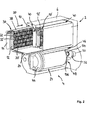
Eine andere Weiterbildung der Erfindung sieht vor, dass die Heißluft-Zubereitungseinrichtung eine Kammer und eine oder mehrere im Heißluftstrom drehbeweglich aufnehmbare Trommel umfasst, welche eingerichtet ist, das Lebensmittel in der Trommel gleichmäßig den die Kammer durchströmenden Heißluftstrom auszusetzen. Bevorzugt weist die Heißluft-Zubereitungseinrichtung eine geschlossene bzw. verschließbare Kammer auf, innerhalb der sich eine mit dem zuzubereitenden Lebensmittel bestückbare Trommel zumindest während der Zubereitungsphase des Lebensmittels drehbeweglich angeordnet ist. Über die Drehung der Trommel ist eine Bewegung des Lebensmittels innerhalb der Trommel erzeugt, ähnlich einer Bewegung beim Waschvorgang in der Trommel einer Waschmaschine. Durch die Drehbewegung der Trommel wird das sich insbesondere aus einer Mehrzahl an Einzelgütern zusammensetzende Lebensmittel gleichmäßig dem erzeugten Heißluftstrom ausgesetzt. Damit kann der Vorgang des Erwärmens, im Vergleich zu einem unbeweglich mit Heißluft beaufschlagtem Lebensmittel, effektiver und gleichzeitig in verkürzter Zeit durchgeführt werden. Bevorzugt bewegt sich die Trommel innerhalb der Kammer kontinuierlich bzw. fortwährend während des Erwärmungsvorgangs des zuzubereitenden Lebensmittels.Another development of the invention provides that the hot-air preparation device comprises a chamber and one or more in the hot air flow rotatably receivable drum, which is adapted to uniformly suspend the food in the drum to the hot air flow flowing through the chamber. The hot-air preparation device preferably has a closed or closable chamber, within which a drum which can be equipped with the food to be prepared is rotatably arranged at least during the preparation phase of the food. Through the rotation of the drum, a movement of the food within the drum is produced, similar to a movement during the washing process in the drum of a washing machine. As a result of the rotational movement of the drum, the food, which is composed in particular of a plurality of individual goods, is exposed uniformly to the generated hot air stream. Thus, the process of heating can be performed more effectively and at the same time in a shortened time, compared to a foodstuff immobile with hot air. Preferably, the drum moves within the chamber continuously during the heating process of the food to be prepared.
Gemäß einer Ausgestaltung der Erfindung weist die Trommel eine bevorzugt zylindrische Formgebung auf und ist mit einer Zentralöffnung zum Einbringen von Heißluft an vorzugsweise einer Stirnwand ausgerüstet. Durch die zylindrische Ausgestaltung der Trommel lässt sich innerhalb der Kammer die Rotationsbewegung der Trommel einfach umsetzen. Die Kammer weist bevorzugt ebenfalls eine zylindrische Ausgestaltung bzw. Formgebung auf, wobei der Innendurchmesser der Kammer nur geringfügig größer ist als der Außendurchmesser der Trommel. Unter geringfügig größer sind hier Abmessungen im Bereich zwischen 2 bis 10 mm zu verstehen. Mittels der bevorzugt an einer ebenen, kreisförmigen Stirnwand ausgebildeten Zentralöffnung der Trommel wird die heiße Luft in das Trommelinnere eingegeben. Über die Zentralöffnung ist eine konzentrierte Zufuhr der erzeugten Heißluft in das Trommelinnere gewährleistet, um eine entsprechend hohe Durchflussrate der Heißluft durch die Trommel zu gewährleisten, weist die Zentralöffnung vorzugsweise einen Durchmesser auf, der ungefähr einem Viertel bis etwa einem Drittel des Trommeldurchmessers entspricht.According to one embodiment of the invention, the drum has a preferably cylindrical shape and is equipped with a central opening for introducing hot air to preferably an end wall. Due to the cylindrical configuration of the drum can be within the chamber, the rotational movement of the drum easily implement. The chamber preferably also has a cylindrical configuration or shape, wherein the inner diameter of the chamber is only slightly larger than the outer diameter of the drum. Below slightly larger dimensions are to be understood in the range between 2 to 10 mm. By means of the preferably formed on a flat, circular end wall central opening of the drum, the hot air is entered into the interior of the drum. Through the central opening, a concentrated supply of hot air generated in the interior of the drum is ensured to ensure a correspondingly high flow rate of the hot air through the drum, the central opening preferably has a diameter which corresponds to about a quarter to about one third of the drum diameter.
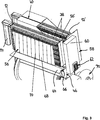
In einer anderen Weiterbildung der Erfindung weist die Trommel einen der Stirnwand mit der Zentralöffnung gegenüberliegend angeordneten Endbereich mit bevorzugt umfangsseitig angeordneten Auslässen auf. Mithilfe der gegenüberliegend zur Zentralöffnung angeordneten Auslässen ist bewirkt, dass der Innenraum der Trommel bestmöglich in Längsrichtung der Trommel von dem Heißluftstrom durchströmt wird. Mittels der gezielten Anordnung von Einlass und Auslass an entgegengesetzten Endbereichen der Trommel sind Trommelabschnitte oder -bereiche vermieden, die nicht vom Heißluftstrom durchströmt werden. Die Auslässe sind vorzugsweise gleichmäßig über den endseitigen Umfangsbereich der Trommel verteilt angeordnet. Bevorzugt bilden die Vielzahl der Auslässe eine sich über den gesamten Umfang der Trommel erstreckenden Auslassbereich aus. Die Auslässe weisen die Form eines sich in Längsrichtung der Trommel erstreckenden Langlochs auf und sind jeweils unmittelbar zueinander benachbart angeordnet. Zwischen zwei benachbart angeordneten Auslässen ist ein Steg vorgesehen, der nur einen Bruchteil der Breite aufweist, wie die Breite des Auslasses in Umfangsrichtung.In another development of the invention, the drum has an end wall with the central opening opposite arranged end region with preferably peripherally arranged outlets. By means of the outlets arranged opposite to the central opening, it is ensured that the interior of the drum is flowed through as best as possible in the longitudinal direction of the drum by the hot air flow. By means of the targeted arrangement of inlet and outlet at opposite end regions of the drum drum sections or areas are avoided, which are not flowed through by the hot air flow. The outlets are preferably arranged distributed uniformly over the end-side peripheral region of the drum. Preferably, the plurality of outlets form an outlet region extending over the entire circumference of the drum. The outlets have the shape of an elongated hole extending in the longitudinal direction of the drum and are each arranged directly adjacent to one another. Between two adjacently arranged outlets a web is provided, which has only a fraction of the width, as the width of the outlet in the circumferential direction.
In einer anderen Ausgestaltung der Erfindung weist die Trommel eine sich entlang ihrer inneren Mantelfläche spiralförmig erstreckende, feststehende Wendel zum Umwälzen der in der Trommel aufgenommenen Lebensmittel auf. Mithilfe der Wendel ist die gleichmäßige Bewegung des eine Vielzahl von Stückgütern aufweisenden Lebensmittels, wie beispielsweise Pommes Frites, verbessert. Die unmittelbar an der Trommelwandung anliegenden Lebensmittel werden bei der Rotation der Trommel zumindest ein stückweit gehalten und bewegen sich über einen vorbestimmten Drehwinkel mit. Durch die Wendel wird ein Rutschen des Lebensmittels entlang der Trommelwandung in Umfangsrichtung verhindert und eine gleichmäßige Durchmischung bewirkt. Dementsprechend gelangt beispielsweise jedes Einzelgut im gleichen Maße in Kontakt mit dem Heißluftstrom wie jedes andere Einzelgut auch. Die Wendel ist bevorzugt aus einem streifenförmigen Blechkörper hergestellt. Bevorzugt wird die Außenkante der Wendel stoffschlüssig mit der Innenseite der Trommel verbunden, insbesondere mit der Innenseite verschweißt.In another embodiment of the invention, the drum has a fixed spiral spirally extending along its inner circumferential surface for circulating the food received in the drum. The helix improves the smooth movement of the food having a variety of articles such as French fries. The directly adjacent to the drum wall food are held at least a bit in the rotation of the drum and move with a predetermined angle of rotation. The helix prevents slippage of the food along the wall of the drum in the circumferential direction and causes a uniform mixing. Accordingly, for example, each individual item gets in contact with the hot air stream to the same extent as any other item. The helix is preferably made of a strip-shaped sheet metal body. Preferably, the outer edge of the coil is firmly bonded to the inside of the drum, in particular welded to the inside.
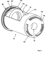
Vorzugsweise ist die Trommel reversibel koppel- und entkoppelbar mit einer in der Kammer drehbar gelagerten Halterung, wobei die Halterung mit einem Antriebsmittel drehgebend gekoppelt ist. Zwischen der Trommel und der Halterung ist eine beliebig oft wiederholbare Entkopplung und Kopplung möglich, sodass die Trommel bevorzugt aus der Kammer der erfindungsgemäßen Heißluft-Zubereitungseinrichtung entnommen und wieder eingesetzt werden kann. Die Halterung weist bevorzugt ein mit einem stirnseitigen Endbereich der Trommel korrespondierendes Aufnahmeteil auf, an dem die Trommel jeweils während der Zubereitung des Lebensmittels in der Trommel vorübergehend befestigt wird. Das Aufnahmeteil ist vorzugsweise ein Rotationskörper, der einen Außenumfang ähnlich dem Durchmesser der Trommel aufweist. Die Halterung für die Trommel ist bevorzugt eine Drehbewegung übertragend mit einem Antriebsmittel mechanisch verbunden. Bevorzugt ist zwischen Antriebsmittel und dem die Trommel haltenden Aufnahmeteil ein als Übersetzungsgetriebe dienendes Koppelgetriebe vorgesehen. Das Antriebsmittel ist vorzugsweise ein Elektromotor, mit dem auf einfache Weise die benötigte Drehbewegung für die Trommel erzeugt werden kann. Das um eine Rotationsachse drehbeweglich aufgenommene Aufnahmeteil weist im Bereich seines Außendurchmessers eine Außenverzahnung auf, die mit einem mit der Antriebswelle des Antriebsmittels gekoppelten Antriebsritzel kämmt. Die von der Trommel umgesetzte Drehzahl beträgt vorliegend ungefähr zwei bis drei Umdrehungen pro Minute. Umdrehungszahlen von vier, fünf oder mehr Umdrehungen pro Minute sind ebenfalls möglich.Preferably, the drum is reversibly coupled and decoupled with a rotatably mounted in the chamber holder, wherein the holder is rotatably coupled to a drive means. Between the drum and the holder as often as possible repeatable decoupling and coupling is possible, so that the drum preferably removed from the chamber of the hot air preparation device according to the invention and can be used again. The holder preferably has a receiving part which corresponds to an end-side end region of the drum and to which the drum is temporarily secured in each case during the preparation of the foodstuff in the drum. The receiving part is preferably a rotary body having an outer circumference similar to the diameter of the drum. The holder for the drum is preferably a rotational movement mechanically connected to a drive means. Preferably, a coupling mechanism serving as a transmission gear is provided between the drive means and the receiving part holding the drum. The drive means is preferably an electric motor with which the required rotational movement for the drum can be generated in a simple manner. In the region of its outer diameter, the receiving part rotatably received about an axis of rotation has an external toothing which meshes with a drive pinion coupled to the drive shaft of the drive means. The speed converted by the drum is presently about two to three revolutions per minute. Revolutions of four, five or more revolutions per minute are also possible.
Zudem weist die Trommel an der Außenseite der bevorzugt die Zentralöffnung aufweisenden Stirnwand mehrere Verriegelungsteile auf, die mit in axialer und/oder radialer Richtung in die Kammer vorstehenden Rastelementen der Halterung korrespondieren. Mithilfe der Verriegelungsteile an der Trommel, die in Richtung der Halterung an der rückseitigen Stirnwand der Trommel vorstehen, und mittels der Rastelemente ist eine beliebig oft reversibel koppel- und entkoppelbare Verbindung, ähnlich einem Bajonettverschluss, auf einfache Weise möglich. Verriegelungsteile und Rastelemente greifen derart korrespondierend ineinander, dass die Trommel in einer Rotationsrichtung drehfest mit dem Aufnahmeteil gekoppelt wird und in die entgegengesetzte Richtung das Lösen der Verbindung erreicht wird. Die drehfeste Verbindung zwischen Trommel und Aufnahmeteil wird dabei durch eine Bewegung der Trommel entgegen der gängigen Antriebsrichtung des die Trommel antreibenden Antriebs hergestellt. Bei einer Bewegung der Trommel in Richtung der Drehbewegung des Antriebsmittels wird die Verbindung zwischen den Verriegelungselementen an der Trommel und den Rastelementen am Aufnahmeteil aufgehoben. Bevorzugt sind mehrere, bevorzugt drei Verriegelungsteile auf einem Teilkreisdurchmesser nahe des Außenumfangs der Trommel im gleichmäßigen Abstand zueinander angeordnet, wodurch eine sichere Drehmomentübertragung gewährleistet ist.In addition, the drum has on the outer side of the front wall preferably having the central opening a plurality of locking parts which correspond with in the axial and / or radial direction in the chamber projecting locking elements of the holder. By means of the locking parts on the drum, which protrude in the direction of the holder on the rear end wall of the drum, and by means of the locking elements is an often reversible coupled and decoupled connection, similar to a bayonet lock, in a simple manner possible. Locking parts and locking elements engage in such a manner corresponding to each other that the drum is rotatably coupled in a rotational direction with the receiving part and in the opposite direction, the release of the connection is achieved. The rotationally fixed connection between the drum and the receiving part is produced by a movement of the drum counter to the usual drive direction of the drive driving the drum. Upon movement of the drum in the direction of the rotational movement of the drive means, the connection between the locking elements on the drum and the latching elements on the receiving part is canceled. Preferably, a plurality, preferably three locking parts are arranged on a pitch circle diameter near the outer circumference of the drum at a uniform distance from each other, whereby a secure torque transmission is ensured.
Bevorzugt weist die Trommel im Mantelbereich eine Befüll- und Entnahmeöffnung auf, welche sich vorzugsweise über mehr als die Hälfte der Trommellänge und über einen Winkel von etwa einem Fünftel des Gesamtumfangs der Trommel erstreckt. Um die zuzubereitenden Lebensmittel in die Trommel eingeben bzw. zu entnehmen können, ist eine Befüll- und Entnahmeöffnung im Bereich des Mantels der Trommel vorgesehen. Die Öffnung am Trommelmantel ermöglicht ein einfaches Bestücken und eine einfache Ausgabe der Lebensmittel nach erfolgter Zubereitung. Vorzugsweise erstreckt sich die Befüll- und Entnahmeöffnung über wenigstens die Hälfte der Trommellänge, bevorzugt über etwa Dreiviertel der Trommellänge. Das Öffnungsmaß in Umfangsrichtung beträgt etwa zwischen einem Sechstel und einem Viertel des Gesamtumfangs der Trommel, bevorzugt etwa einem Fünftel des Gesamtumfangs, was etwa 75° entspricht. Die Befüllöffnung ist mit einer die Befüll- und Entnahmeöffnung verschließenden Abdeckung ausrüstbar.Preferably, the drum in the shell region on a filling and removal opening, which preferably extends over more than half of the drum length and over an angle of about one fifth of the total circumference of the drum. To be able to enter or remove the foodstuffs to be prepared in the drum, a filling and removal opening is provided in the region of the jacket of the drum. The opening on the drum shell allows easy placement and easy dispensing of food after preparation. Preferably, the filling and removal opening extends over at least half of the drum length, preferably over about three quarters of the drum length. The opening dimension in the circumferential direction is approximately between a sixth and a quarter of the total circumference of the drum, preferably about one fifth of the total circumference, which corresponds to about 75 °. The filling opening is with a covering the filling and removal opening cover.
Bevorzugt weist die Trommel einen die Öffnung der Kammer im Gerätegehäuse abdeckenden, bevorzugt transparenten Deckel auf, welcher starr mit dem Trommelmantel verbunden ist. Die erfindungsgemäße Vorrichtung weist anstelle eines schwenkbar an der Frontseite des Gerätegehäuses angeordneten Kammerdeckels einen unmittelbar mit dem Trommelmantel fest verbundenen Deckel auf. Der Deckel führt damit im Betrieb der Heißluft-Zubereitungseinrichtung zusammen mit der Trommel eine Drehbewegung aus. Darüber ist auf vorteilhaft einfache Weise erkennbar, ob die Heißluft-Zubereitungseinrichtung noch in Betrieb ist oder die Zubereitungphase des in der Trommel aufgenommenen Lebensmittels abgeschlossen ist.Preferably, the drum has an opening of the chamber in the device housing covering, preferably transparent lid, which is rigidly connected to the drum shell. The device according to the invention has, instead of a pivotally arranged on the front side of the device housing chamber lid on a directly connected to the drum shell cover. The lid thus performs a rotational movement together with the drum during operation of the hot-air preparation device. It can be seen in an advantageously simple manner, whether the hot air preparation device is still in operation or the preparation phase of the recorded in the drum food is completed.
Zudem ist bevorzugt an dem Deckel ein Griffteil zum reversiblen Entkoppeln und Koppeln der Trommel von Hand von und mit der Halterung in der Kammer der erfindungsgemäßen Heißluft-Zubereitungseinrichtung vorgesehen ist. Mithilfe des am Deckel angeordneten Griffteils erfolgt das Lösen der Trommel am Aufnahmeteil und das Entnehmen der Trommel aus der Kammer, um beispielsweise die Trommel mit einer Portion eines zuzubereitenden Lebensmittels, wie beispielsweise Pommes Frites, zu bestücken. Nach dem Befüllen der Trommel wird dann die Trommel über das Griffteil in die Kammer eingeschoben und durch eine Drehung der Trommel, entgegen der üblichen Antriebsrichtung innerhalb der Kammer, wird die Trommel wieder mit dem Aufnahmeteil der Halterung gekoppelt. Bei der Kopplung der Trommel mit dem Aufnahmeteil werden die Verriegelungselemente der Trommel mit den Rastelementen am Aufnahmeteil der Halterung verrastet. Der die Trommel frontseitig verschließende Deckel ist vorzugsweise mit einer isolierend wirkenden Doppelverglasung ausgerüstet.In addition, a handle part for reversibly decoupling and coupling the drum by hand from and with the holder in the chamber of the hot air preparation device according to the invention is preferably provided on the lid. By means of the cover arranged on the handle part, the detachment of the drum on the receiving part and the removal of the drum from the chamber, for example, to equip the drum with a portion of a food to be prepared, such as French fries. After filling the drum, the drum is then inserted over the handle in the chamber and by rotation of the drum, contrary to the usual drive direction within the chamber, the drum is again coupled to the receiving part of the holder. In the coupling of the drum with the receiving part, the locking elements of the drum are latched with the locking elements on the receiving part of the holder. The drum, which closes the drum at the front, is preferably equipped with insulating double-glazing.
Um bei der Zubereitung der Lebensmittel in der sich drehenden Trommel zu verhindern, dass Einzelstücke des Lebensmittels zwischen die Außenseite der Trommel und die Innenseite der Kammer gelangen, ist in einer Ausgestaltung der Erfindung vorgesehen, den Abstand geringer als einen Millimeter auszubilden. Eine alternative Ausgestaltung der Erfindung sieht vor, dass entlang der Entnahmeöffnung ein Abdichtmittel angeordnet ist, das nach dem Einsetzen in Anlage mit der Innenseite der Kammer gelangt und den Spalt bevorzugt vollständig abdichtet. Eine weitere alternative Ausgestaltung sieht die Verwendung einer die Befüll- und Entnahmeöffnung verschließenden, aufsetzbaren und abnehmbaren Abdeckung vor.In order to prevent the preparation of food in the rotating drum that individual pieces of food between the outside of the drum and the inside of the chamber, it is provided in one embodiment of the invention to form the distance less than one millimeter. An alternative embodiment of the invention provides that a sealing means is arranged along the removal opening, which comes into contact with the inside of the chamber after insertion and preferably completely seals the gap. Another alternative embodiment provides for the use of a filling and removal opening closing, attachable and removable cover.
In einer anderen Ausgestaltung der erfindungsgemäßen Vorrichtung weist die drehbare Trommel ein oder mehrere mit der Kammerrückwand oder dem Heißluft-Einlass und/oder der Deckel der Trommel mit der Außenseite der Gerätefront des Gerätegehäuses in abdichtende Anlage bringbare Dichtungsteile auf. Bevorzugt wird an beiden Stirnseiten der Trommel eine Labyrinthdichtung ausgebildet. Mittels der Labyrinthdichtung wird vermieden, dass der durch die Trommel strömende Heißluftstrom einen nicht gewollten Weg innerhalb des Gerätegehäuses geht oder an Wandbereichen aus dem Gerätegehäuse austritt, die nicht dafür bestimmt sind. Mithilfe der Dichtungsteile, welche beispielsweise typische Gummidichtungen sein können, wird einem ungewollten Austritt der Heißluft und möglicher damit mitgetragener Dunst oder Geruchspartikel an der Öffnung der Kammer entgegengewirkt. Daher ist mittels der erfindungsgemäßen Heißluft-Zubereitungseinrichtung eine Zubereitung von Lebensmitteln möglich, die bei der Zubereitung von Lebensmittel eine deutlich reduzierte Geruchsbelastung verursacht.In another embodiment of the device according to the invention, the rotatable drum has one or more with the chamber rear wall or the hot air inlet and / or the lid of the drum with the outside of the front of the device housing in sealing abutment sealable sealing parts. Preferably, a labyrinth seal is formed on both end faces of the drum. By means of the labyrinth seal it is avoided that the stream of hot air flowing through the drum goes an undesired path within the device housing or emerges from the device housing on wall areas which are not intended for this purpose. By means of the sealing parts, which may be typical rubber seals, for example, unwanted escape of the hot air and possible haze or odor particles carried along with it are counteracted at the opening of the chamber. Therefore, by means of the hot air preparation device according to the invention a preparation of foods is possible, which causes a significantly reduced odor in the preparation of food.
Gemäß einer anderen Ausgestaltung der erfindungsgemäßen Vorrichtung weist die Kammer im Bodenbereich ein aus der Kammer entnehmbares Aufnahmereservoir für flüssige Rückstände auf. Bevorzugt bei der Herstellung bzw. Zubereitung der Lebensmittel im inneren der Kammer entstehende Dämpfe oder Flüssigkeiten, die sich an der Innenseite der Kammer ablagern, werden über das im Bodenbereich vorhandene Aufnahmereservoir aufgefangen. Das Aufnahmereservoir ist beispielsweise als eine rinnenartige Vertiefung im Bodenbereich der Kammer ausgebildet. Vorzugsweise ist das Aufnahmereservoir mit einer für Flüssigkeiten durchlässige Abdeckung abgedeckt. Eine Ausgestaltung der Erfindung sieht vor, dass das Aufnahmereservoir eine aus der Kammer entnehmbare Auffangschale umfasst.According to another embodiment of the device according to the invention, the chamber in the bottom region on a removable from the chamber receiving reservoir for liquid residues. Preferably in the production or preparation of the food in the interior of the chamber resulting vapors or liquids that are deposited on the inside of the chamber are collected on the existing in the bottom area receiving reservoir. The receiving reservoir is formed, for example, as a groove-like depression in the bottom region of the chamber. Preferably, the receiving reservoir is covered with a liquid-permeable cover. An embodiment of the invention provides that the receiving reservoir comprises a removable from the chamber drip tray.
Bevorzugt weist die Kammer eine Innenwandung mit einer die Reinigung begünstigenden Oberfläche auf. Dadurch ist sichergestellt, dass an der Innenwandung anhaftende Rückstände von einem zuvor vorgenommenen Zubereitungsvorgang einfach von der Innenwandung der Kammer entfernt werden können. Die Innenwandung der Kammer kann beispielsweise mit einer Beschichtung ausgerüstet sein, die beispielsweise die Reinigung begünstigt oder das Anhaften von Verschmutzungen grundsätzlich erschwert. Optional ist vorgesehen, dass die Trommel eine die Reinigung begünstigende Oberfläche auf der den Aufnahmeraum für die Lebensmittel aufnehmenden Innenseite und auch der der Kammerwandung zugewandten Außenseite aufweist.The chamber preferably has an inner wall with a surface that promotes cleaning. This ensures that adhering to the inner wall residues can be easily removed from a previously made preparation process of the inner wall of the chamber. The inner wall of the chamber, for example, be equipped with a coating that favors, for example, the cleaning or the adhesion of soils fundamentally difficult. Optionally, it is provided that the drum has a cleaning-promoting surface on the receiving space for the food-receiving inside and also the chamber wall facing the outside.
Eine weitere Ausgestaltung der erfindungsgemäßen Vorrichtung schlägt vor, dass die Heißluft-Zubereitungseinrichtung eine Zugabeeinheit zum bevorzugt tropfenförmigen Hinzugeben von Flüssigkeit in den Heißluftstrom aufweist. Mittels der mit dem Heißluftstrom verbundenen können Zugabestoffe, wie beispielsweise Fett oder Öl, in den durch das Gerätegehäuse geführten Heißluftstrom eingegeben werden, die den Zubereitungsvorgang des Lebensmittels in der Trommel begünstigen bzw. beschleunigen. Die Zugabeeinheit weist bevorzugt eine Dosierpumpe auf, welche mit einem Sammelbehälter fluidleitend gekoppelt ist, aus dem die hinzu zugebende Flüssigkeit angesaugt wird. Die Dosierpumpe gibt die Flüssigkeit bevorzugt in Abhängigkeit von der beispielsweise innerhalb der Trommel erfassten bzw. gemessenen Zusammensetzung des Heißluftstromes in diesen ab.Another embodiment of the device according to the invention proposes that the hot-air preparation device has an addition unit for the preferably drop-shaped addition of liquid into the hot air stream. By means of the connected to the hot air flow can Additives, such as grease or oil, are introduced into the hot air stream passing through the apparatus housing, which promote or accelerate the process of preparing the food in the drum. The addition unit preferably has a metering pump, which is coupled in a fluid-conducting manner to a collecting container, from which the liquid to be added is sucked in. The metering pump preferably delivers the liquid into the hot air stream as a function of the composition of the hot air flow detected or measured, for example, within the drum.
Eine Weiterbildung der erfindungsgemäßen Vorrichtung zeichnet sich durch einen die Heißluft-Zubereitungseinrichtung mit der Aufnahmeeinrichtung für die Fleischerzeugnisse verbindenden, bevorzugt eine Teilmenge des Heißluftstromes überleitenden Kanal aus. Der innerhalb der Heißluft-Zubereitungseinrichtung erzeugte Heißluftstrom wird in einer optionalen Ausgestaltung der Erfindung verwendet, um die Aufnahmeeinrichtung für die zu garenden Fleischerzeugnisse, auch als Grilleinrichtung bezeichnet, vorzuwärmen bzw. während des Garvorgangs zusätzlich zumindest ein Teil der von der Heißluft-Zubereitungseinrichtung erzeugten Heißluft in die Grilleinrichtung zu leiten. Darüber ist eine gleichmäßigere Verkrustung der Oberflächen der Fleischerzeugnisse in der Grilleinrichtung erreicht. Durch die auf die Fleischerzeugnisse geleitete Heißluft nimmt die Oberfläche zudem eine beschleunigte Brauntönung an. Um zumindest eine Teilmenge des Heißluftstromes von der Heißluft-Zubereitungseinrichtung in die Aufnahmeeinrichtung, auch bezeichnet als Grilleinrichtung, für die Fleischerzeugnisse überleiten zu können, weist die erfindungsgemäße Vorrichtung einen bei den Komponenten miteinander verbindenden Kanal auf. Der Überleitungskanal kann bevorzugt gezielt geöffnet und verschlossen werden, sodass das Überleiten der Heißluft in die Aufnahmeeinrichtung für die Fleischerzeugnisse bedarfsgerecht erfolgen kann.A further development of the device according to the invention is characterized by a channel connecting the hot-air preparation device to the receiving device for the meat products, preferably a subset of the hot air flow. The hot air stream generated within the hot air preparation device is used in an optional embodiment of the invention to preheat the receiving device for the meat products to be cooked, also referred to as a grill device, or at least a portion of the hot air generated by the hot air preparation device during the cooking process to guide the barbecue. In addition, a more uniform crusting of the surfaces of the meat products is achieved in the grill. Due to the hot air conducted on the meat products, the surface also assumes an accelerated browning. In order to be able to transfer at least a subset of the hot air flow from the hot-air preparation device into the receiving device, also referred to as a grill device, for the meat products, the device according to the invention has a channel interconnecting the components. The transfer channel can preferably be selectively opened and closed, so that the passing of the hot air into the receiving device for the meat products can be done as needed.
Die Heißluft-Zubereitungseinrichtung ist mit einer bevorzugt elektronischen Steuereinheit zum Steuern der Temperatur und/oder Zubereitungszeit signalleitend gekoppelt. Mithilfe der Steuereinheit erfolgt bevorzugt die Regelung der Temperatur innerhalb der die Trommel aufnehmenden Kammer sowie die Regelung der Zubereitungszeit des in der Trommel zu zubereitenden Lebensmittels. Gleichzeitig erfolgt mit der elektronischen Steuereinheit auch das Steuern der Drehbewegung des Antriebsmittels für die Trommel. Dadurch lässt sich das Anfahren und/oder Anhalten der Trommel bezogen auf einen vorbestimmten Drehwinkel in der Kammer gezielt steuern. Das Antriebsmittel, welches bevorzugt ein Schrittmotor aufweist, wird derart gesteuert angetrieben, dass die Trommel angehalten wird, dass die Befüll- und Entnahmeöffnung am Umfang der Trommel ungefähr eine Viertelkreisdrehung vor Erreichen ihrer oberen Stellung steht. Durch Verdrehen der Trommel von Hand mittels des Griffteils wird die Verbindung der Trommel zum Aufnahmeteil gelöst und gleichzeitig die Befüll- und Entnahmeöffnung in die obere Stellung der Kammer bewegt. Die Trommel kann nun entnommen werden, ohne das Risiko, dass das in der Trommel befindliche bereits zubereitete Lebensmittel über die nunmehr nach oben weisenden Öffnung ungewollt herausfällt. Eine alternative Ausgestaltung der Erfindung sieht vor, dass die Heißluft-Zubereitungseinrichtung und die Aufnahmeeinrichtung für die Fleischerzeugnisse, auch als Grilleinrichtung bezeichnet, jeweils eine elektronische Steuereinheit aufweist. Eine bevorzugte Ausgestaltung sieht jedoch vor, dass die Grilleinrichtung und die Heißluft-Zubereitungseinrichtung über eine gemeinsame elektronische Steuereinheit gesteuert werden.The hot air preparation device is signal-coupled to a preferably electronic control unit for controlling the temperature and / or preparation time. By means of the control unit is preferably carried out the regulation of the temperature within the chamber receiving the drum and the regulation of the preparation time of the food to be prepared in the drum. At the same time, the electronic control unit also controls the rotational movement of the drive means for the drum. This makes it possible to selectively control the starting and / or stopping of the drum relative to a predetermined angle of rotation in the chamber. The drive means, which preferably comprises a stepper motor, is driven in a controlled manner so that the drum is stopped, that the filling and removal opening on the circumference of the drum is about a quarter of a circle rotation before reaching its upper position. By turning the drum by hand by means of the handle part, the connection of the drum is released to the receiving part and simultaneously moves the filling and removal opening in the upper position of the chamber. The drum can now be removed without the risk that the already prepared food in the drum accidentally falls over the now upwardly facing opening. An alternative embodiment of the invention provides that the hot-air preparation device and the receiving device for the meat products, also referred to as a grill device, each having an electronic control unit. However, a preferred embodiment provides that the grill device and the hot air preparation device are controlled by a common electronic control unit.
Die Steuereinheit ist vorzugsweise signalleitend mit Sensormitteln zum Erfassen der Temperatur in der Aufnahmeeinrichtung für die Fleischerzeugnisse und/oder der Heißluftzubereitungseinrichtung und/oder mit optischen und/oder akustischen Signalgebern zur Ausgabe von Hinweissignalen verbunden. Mithilfe der Sensormittel können relevante für die Zubereitung in der Grilleinrichtung für die Fleischerzeugnisse und in der Heißluft-Zubereitungseinrichtung vorhandene Zustandsgrößen, wie z. B. die Temperatur oder die Zusammensetzung in der Heißluft überwacht und geregelt werden. Ebenso lassen sich die Offenstellung bzw. Verschlussstellung möglicher Klappen im Kanal für den durch das Gerätegehäuse geführten Heißluftstrom überwachen und regeln.The control unit is preferably signal-conducting connected to sensor means for detecting the temperature in the receiving means for the meat products and / or the hot air preparation device and / or with optical and / or acoustic signal generators for output of indication signals. With the aid of the sensor means, relevant state variables for the preparation in the grilling device for the meat products and in the hot-air preparation device, such as eg. As the temperature or the composition in the hot air are monitored and regulated. Likewise, the open position or closed position of possible flaps in the channel can be monitored and regulated for the hot air flow guided through the device housing.
Als Sensormittel kommen beispielsweise Temperatursensoren, Drucksensoren oder Feuchtigkeitssensoren oder Endlagenschalter zum Einsatz. Mithilfe optischer und/oder akustischer Signalgeber kann beispielsweise das Überschreiten voreinstellbarer Temperaturgrenzwerte oder auch das Erreichen der voreinstellbaren Garzeit angezeigt werden. Als optische oder akustische Signalgeber werden beispielsweise Leuchtmittel oder Lautsprecher eingesetzt.As a sensor means, for example, temperature sensors, pressure sensors or humidity sensors or limit switches are used. With the aid of optical and / or acoustic signal transmitters, for example, the exceeding of presettable temperature limit values or even the achievement of the presettable cooking time can be displayed. As an optical or acoustic signal generator lamps or speakers are used, for example.
Gemäß einer Ausgestaltung der erfindungsgemäßen Vorrichtung zeichnet sich diese durch eine Filtereinheit aus, über die der durch das Gerätegehäuse geführte Luftstrom geleitet wird, welche vorzugsweise stromabwärts der Aufnahmeeinrichtung für die Fleischerzeugnisse angeordnet ist. Mithilfe der Filtereinheit wird vermieden, dass mit dem Heißluftstrom mitgeführte Geruchs- oder Feuchtigkeitspartikel in die Umgebung gelangen. Die Filtereinheit ist bevorzugt einem Auslass für den durch das Gerätegehäuse geleiteten Heißluftstrom vorgeschaltet angeordnet. Die durch die erfindungsgemäße Vorrichtung erzeugte Geruchsbelastung kann durch die Filtereinheit auf ein Minimum reduziert werden, wodurch der Einsatz in Schnellrestaurants und Imbissbetrieben ohne Probleme möglich ist. Die Filtereinheit weist ein oder mehrere Filterelemente auf, welche Aktivkohle und andere Filterstoffe enthalten. Die Filtereinheit ist bevorzugt eingerichtet, einen Großteil der Geruchsemmission der mittels der erfindungsgemäßen Vorrichtung umgesetzten Garprozesse aus Grilleinrichtung und Heißluft-Zubereitungseinrichtung zu absorbieren.According to one embodiment of the device according to the invention, this is characterized by a filter unit, via which the guided through the device housing air flow is passed, which is preferably arranged downstream of the receiving device for the meat products. The filter unit prevents odors or moisture particles entrained in the hot air flow from entering the environment. The filter unit is preferably arranged upstream of an outlet for the guided through the device housing hot air flow. The odor stress generated by the device according to the invention can be reduced to a minimum by the filter unit, whereby the use in fast food restaurants and fast food establishments is possible without any problems. The filter unit has one or more filter elements containing activated carbon and other filter materials. The filter unit is preferably set up to absorb a large part of the odor emission of the cooking processes from the grill device and hot air preparation device implemented by means of the device according to the invention.
Eine optionale Ausgestaltung der Erfindung sieht vor, dass auf der Geräteoberseite zusätzlich ein Brühwursterhitzer angeordnet ist. Bevorzugt nutzt der Brühwursterhitzer die Abwärme der Grilleinrichtung und der Heißluft-Zubereitungseinrichtung. Der Brühwursterhitzer weist einen hitzebeständigen Behälter, beispielsweise aus Glas, auf, mit einem an der Oberseite des Behälters öffenbaren und verschließbaren Deckel. In dem Behälter befindet sich eine Vorratsgefäß mit einer Menge an Wasser, das durch die an den Behälter abgegebene Abwärme erhitzt wird und darüber das Wasser in der Schale auf eine Temperatur von bevorzugt 70° bis 90°C erwärmt wird. Oberhalb der Schale ist ein Gitter für darüber aufnehmbare Brühwürste angeordnet. Über den aus dem Vorratsgefäß aufsteigenden Wasserdampf werden die darüber befindlichen Brühwürste erwärmt, welche durch die Berührung mit ausschließlich dem Wasserdampf über mehrere Stunden für den Verzehr bereit gehalten werden können.An optional embodiment of the invention provides that a Brühwursterhitzer is additionally arranged on the top of the device. Preferably, the Brühwursthitzer uses the waste heat of the grill and the hot air preparation device. The Brühwursterhitzer has a heat-resistant container, for example made of glass, with a lid which can be opened and closed at the top of the container. In the container is a storage vessel with an amount of water, which is heated by the heat given off to the container waste heat and above the water in the shell is heated to a temperature of preferably 70 ° to 90 ° C. Above the shell, a grid for overflowable cooked sausages is arranged. About the ascending from the storage vessel steam above the scalded sausages are heated, which can be kept ready for consumption by the contact with only the water vapor for several hours.
Im Folgenden wird die Erfindung anhand eines bevorzugten Ausführungsbeispiels unter Bezugnahme auf die beigefügten Figuren näher beschrieben. Hierbei zeigen:In the following the invention with reference to a preferred embodiment with reference to the accompanying figures will be described in more detail. Hereby show:
In
Die Aufnahmeeinrichtung
Wie
Die drehbar gelagerte Trommel
Die
Wie
BezugszeichenlisteLIST OF REFERENCE NUMBERS
- 11
- Vorrichtungcontraption
- 22
- GrilleinrichtungGrill facility
- 44
- Heißluft-ZubereitungseinrichtungHot-air cooking apparatus
- 66
- Gerätegehäusedevice housing
- 88th
- Abschnittsection
- 10, 10'10, 10 '
- Aufnahmefachreceiving compartment
- 11, 11', 4311, 11 ', 43
- Öffnungopening
- 12, 12'12, 12 '
- Einsetzkassettein cartridge
- 1414
- Handgriffhandle
- 1616
- GerätegehäusefrontDevice housing front
- 1818
- Einschubinsertion
- 2020
- Auffangbehälterreceptacle
- 2222
- Zylindrischer AbschnittCylindrical section
- 2424
- Trommeldrum
- 26, 26'26, 26 '
- Bedien-, RegelelementeOperating and control elements
- 2828
- Anzeigeeinrichtungdisplay
- 2929
- Außenhülleouter shell
- 30, 30'30, 30 '
- SeitenwandSide wall
- 32, 32'32, 32 '
- Durchbruchbreakthrough
- 3434
- Heizeinrichtungheater
- 3636
- Fleischerzeugnismeat product
- 3838
- Anschlagelementstop element
- 3939
- Einsetzrichtunginsertion
- 4040
- Führungguide
- 4242
- Kammerchamber
- 4444
- Deckelcover
- 4646
- Abluftkanalexhaust duct
- 4848
- Halterungbracket
- 5050
- Antriebsmitteldrive means
- 5252
- Koppelgetriebecoupling gear
- 5454
- Antriebsritzelpinion
- 56, 56'56, 56 '
- Heizelementheating element
- 5858
- Abluft-FiltereinheitExhaust air filter unit
- 6060
- Filterelementfilter element
- 6262
- Auslassöffnungoutlet
- 6464
- Bodenplattebaseplate
- 6666
- Einblasöffnungeninjection openings
- 6868
- Trägerplattesupport plate
- 7070
- Widerstandsdrahtresistance wire
- 72, 72'72, 72 '
- Hüllenteilecover parts
- 74, 74'74, 74 '
- Griffträgerhandle support
- 7575
- Verriegelungsabschnittlocking section
- 75'75 '
- Vorsprunghead Start
- 7676
- Scharnierehinges
- 7878
- Aufnahmeraumaccommodation space
- 80, 80' 80, 80 '
- StegeStege
- 82, 82'82, 82 '
- Einlegefachinsert tray
- 8484
- Bodenbereichfloor area
- 8686
- Aufnahmereservoirreceiving reservoir
- 8888
- Griffteilhandle part
- 9090
- Gebläsefan
- 9292
- Heizgerätheater
- 9494
- Zentralöffnungcentral opening
- 9696
- Mantelcoat
- 9898
- Endbereichend
- 100, 100'100, 100 '
- Auslassoutlet
- 102102
- Abluftführungexhaust air
- 104104
- Dichtungsteilsealing part
- 106106
- Aufnahmeteilreceiving part
- 108108
- Außenverzahnungexternal teeth
- 110110
- Wendelspiral
- 112112
- Mantelflächelateral surface
- 114114
- Befüll-, EntnahmeöffnungFilling, removal opening
- 116116
- Stirnwandbulkhead
- 118118
- Verriegelungsteillocking member
- 120120
- Rastelementlocking element
- 122122
- Durchbruchbreakthrough
- 124124
- Heißluft-EinlassHot air inlet
ZITATE ENTHALTEN IN DER BESCHREIBUNG QUOTES INCLUDE IN THE DESCRIPTION
Diese Liste der vom Anmelder aufgeführten Dokumente wurde automatisiert erzeugt und ist ausschließlich zur besseren Information des Lesers aufgenommen. Die Liste ist nicht Bestandteil der deutschen Patent- bzw. Gebrauchsmusteranmeldung. Das DPMA übernimmt keinerlei Haftung für etwaige Fehler oder Auslassungen.This list of the documents listed by the applicant has been generated automatically and is included solely for the better information of the reader. The list is not part of the German patent or utility model application. The DPMA assumes no liability for any errors or omissions.
Zitierte PatentliteraturCited patent literature
- DE 202009007012 U1 [0005] DE 202009007012 U1 [0005]
Claims (34)
Priority Applications (8)
| Application Number | Priority Date | Filing Date | Title |
|---|---|---|---|
| DE202014005299.9U DE202014005299U1 (en) | 2014-07-01 | 2014-07-01 | Device for heating and / or cooking meat products |
| DK15162664.5T DK2962608T3 (en) | 2014-07-01 | 2015-04-07 | Apparatus for heating and / or preparing meat products |
| ES15162664T ES2747785T3 (en) | 2014-07-01 | 2015-04-07 | Device for heating and / or cooking meat products |
| EP15162664.5A EP2962608B1 (en) | 2014-07-01 | 2015-04-07 | Device for heating and/or cooking meat products |
| US15/320,792 US10524615B2 (en) | 2014-07-01 | 2015-06-03 | Apparatus for heating and/or cooking meat products |
| EP15729773.0A EP3164038B1 (en) | 2014-07-01 | 2015-06-03 | Apparatus for heating and/or cooking meat products |
| CN201580035745.4A CN106455864B (en) | 2014-07-01 | 2015-06-03 | Equipment for heating and/or simmering meat products |
| PCT/EP2015/062412 WO2016000900A1 (en) | 2014-07-01 | 2015-06-03 | Apparatus for heating and/or cooking meat products |
Applications Claiming Priority (1)
| Application Number | Priority Date | Filing Date | Title |
|---|---|---|---|
| DE202014005299.9U DE202014005299U1 (en) | 2014-07-01 | 2014-07-01 | Device for heating and / or cooking meat products |
Publications (1)
| Publication Number | Publication Date |
|---|---|
| DE202014005299U1 true DE202014005299U1 (en) | 2015-10-09 |
Family
ID=52811051
Family Applications (1)
| Application Number | Title | Priority Date | Filing Date |
|---|---|---|---|
| DE202014005299.9U Expired - Lifetime DE202014005299U1 (en) | 2014-07-01 | 2014-07-01 | Device for heating and / or cooking meat products |
Country Status (7)
| Country | Link |
|---|---|
| US (1) | US10524615B2 (en) |
| EP (2) | EP2962608B1 (en) |
| CN (1) | CN106455864B (en) |
| DE (1) | DE202014005299U1 (en) |
| DK (1) | DK2962608T3 (en) |
| ES (1) | ES2747785T3 (en) |
| WO (1) | WO2016000900A1 (en) |
Cited By (3)
| Publication number | Priority date | Publication date | Assignee | Title |
|---|---|---|---|---|
| DE202017101922U1 (en) | 2017-03-31 | 2017-05-26 | Reamotion Gmbh | Device for heating and / or cooking food |
| DE202017105946U1 (en) | 2017-09-28 | 2018-01-09 | Reamotion Gmbh | Device for the automated heating and / or cooking of food |
| DE202019101468U1 (en) | 2019-03-14 | 2019-03-29 | Reamotion Gmbh | Device for heating and / or cooking food |
Families Citing this family (10)
| Publication number | Priority date | Publication date | Assignee | Title |
|---|---|---|---|---|
| DE102016217375A1 (en) * | 2016-09-13 | 2018-03-15 | Robert Bosch Gmbh | Cassette made of plastic with heating device |
| US11266266B2 (en) * | 2017-06-06 | 2022-03-08 | Manitowoc Fsg Operations, Llc | Food product adapter for vertical grill |
| CN108185833A (en) * | 2017-12-30 | 2018-06-22 | 郑州默尔电子信息技术有限公司 | A kind of food processing circulated air oven |
| CN110179314B (en) * | 2018-02-22 | 2022-08-12 | 深圳市饭立得科技有限公司 | Method, device and system for heating cooked food |
| CN212346260U (en) | 2019-02-26 | 2021-01-15 | 沙克忍者运营有限责任公司 | Cooking system capable of being positioned on a support surface and mountable cooking system |
| CA3153065A1 (en) | 2019-07-15 | 2021-01-21 | Sharkninja Operating Llc | Multiple compartment countertop cooking system |
| US20220287510A1 (en) * | 2019-07-29 | 2022-09-15 | Bcc Product Development, L.L.C. | System and method for heating food |
| CN113491454A (en) | 2020-04-06 | 2021-10-12 | 沙克忍者运营有限责任公司 | Cooking system positionable on a support surface |
| CN111671292B (en) * | 2020-05-28 | 2021-10-22 | 宁波方太厨具有限公司 | Prevent interior container structure of tainting with flavor and have cooking device of this structure |
| US12137838B2 (en) | 2020-12-30 | 2024-11-12 | Sharkninja Operating Llc | Cooking device and components thereof |
Citations (9)
| Publication number | Priority date | Publication date | Assignee | Title |
|---|---|---|---|---|
| DE935570C (en) * | 1939-12-14 | 1955-11-24 | Aeg | Electric bread roaster |
| US3046870A (en) * | 1960-11-15 | 1962-07-31 | Bork Adam | Toaster accessory |
| DE3519964A1 (en) * | 1985-06-04 | 1986-12-04 | Heinrich 5000 Köln Koller | Table-top frying appliance for precooked chips |
| EP0379755A1 (en) * | 1989-01-24 | 1990-08-01 | Hobart Corporation | Rotary continuous conveying oven and cooking chamber therefor |
| DE4401281C1 (en) * | 1994-01-18 | 1995-01-26 | Eloma Gmbh | Apparatus for cooking food in the form of pieces |
| US5735191A (en) * | 1997-06-17 | 1998-04-07 | Russell; Gordon K. | Cooking appliance for meat and buns |
| US6079319A (en) * | 1998-11-13 | 2000-06-27 | Termozeta S.P.A. | Domestic electric device for cooking food |
| US20040144774A1 (en) * | 2003-01-27 | 2004-07-29 | Samsung Electronics Co., Ltd. | Microwave oven |
| DE202009007012U1 (en) | 2009-05-15 | 2009-08-27 | Rennies, Felix | Device for cooking sausages |
Family Cites Families (22)
| Publication number | Priority date | Publication date | Assignee | Title |
|---|---|---|---|---|
| US1729552A (en) * | 1928-04-10 | 1929-09-24 | Shadley Bert | Combination broiler and toaster |
| US1870619A (en) * | 1928-07-05 | 1932-08-09 | Technidyne Corp | Roaster |
| US1910682A (en) * | 1932-03-15 | 1933-05-23 | Dumas Joseph Arthur | Electric oven |
| US2689517A (en) * | 1951-08-03 | 1954-09-21 | William N Angelus | Combination broiler and toaster |
| CA1045926A (en) * | 1977-10-20 | 1979-01-09 | Richard C. Winkler | Cooking apparatus for foodstuffs |
| JP2735952B2 (en) * | 1994-04-11 | 1998-04-02 | シン ヤング カンパニー リミテッド | Barbecue utensils |
| JPH08206009A (en) * | 1995-02-03 | 1996-08-13 | Ishikawa Motors:Kk | Spit support device |
| DE19730829A1 (en) * | 1997-07-18 | 1999-01-28 | Riesselmann Gottfried | Device for heating food |
| JP2000271016A (en) * | 1999-03-24 | 2000-10-03 | Ugajin Seisakusho:Kk | Chinese meat-and-vegetable fried dumpling frying and steaming device of consecutive type |
| US6444955B1 (en) | 2000-09-27 | 2002-09-03 | Ultravection International, Inc. | Cooking enhancing convection oven and method of enhancing the cooking in a convection oven |
| CA2473561C (en) * | 2001-08-20 | 2010-11-02 | A.M. Stephanou | An interchangeable multi-purpose cooking apparatus |
| CN2640382Y (en) * | 2003-09-04 | 2004-09-15 | 深圳市宝安区西乡镇臣田唐锋电器厂 | Cooking arrangement with slidable control box |
| SE525827C2 (en) * | 2003-09-08 | 2005-05-10 | Whirlpool Co | Microwave oven with convection heating |
| KR20050026610A (en) * | 2003-09-09 | 2005-03-15 | 삼성전자주식회사 | Grill cooker and complex cooking apparatus having the grill cooker |
| FR2874805B1 (en) * | 2004-09-09 | 2008-05-23 | Seb Sa | OPTIMIZED DECOMPRESSION COOKING UNDER PRESSURE COOKER |
| KR20050118089A (en) * | 2004-12-02 | 2005-12-15 | 정찬흥 | Charcoal fire roasted machine |
| CN200963083Y (en) * | 2006-09-26 | 2007-10-24 | 何欣儒 | Household combined baking and heat preservation cooking device |
| US7802515B2 (en) * | 2007-11-29 | 2010-09-28 | Sharp Kabushiki Kaisha | Drawer-type heating cooker |
| US8109205B1 (en) * | 2008-01-15 | 2012-02-07 | Met Club Manager, LLC | Vertical grilling apparatus |
| EP2532971A1 (en) * | 2011-06-07 | 2012-12-12 | Koninklijke Philips Electronics N.V. | Apparatus for preparing food |
| EP2770887A1 (en) * | 2011-10-24 | 2014-09-03 | Manitowoc Foodservice Companies, LLC | Compact holding cabinet |
| JP2015010743A (en) * | 2013-06-27 | 2015-01-19 | シャープ株式会社 | Cooking equipment |
-
2014
- 2014-07-01 DE DE202014005299.9U patent/DE202014005299U1/en not_active Expired - Lifetime
-
2015
- 2015-04-07 DK DK15162664.5T patent/DK2962608T3/en active
- 2015-04-07 ES ES15162664T patent/ES2747785T3/en active Active
- 2015-04-07 EP EP15162664.5A patent/EP2962608B1/en active Active
- 2015-06-03 EP EP15729773.0A patent/EP3164038B1/en active Active
- 2015-06-03 WO PCT/EP2015/062412 patent/WO2016000900A1/en not_active Ceased
- 2015-06-03 CN CN201580035745.4A patent/CN106455864B/en not_active Expired - Fee Related
- 2015-06-03 US US15/320,792 patent/US10524615B2/en active Active
Patent Citations (9)
| Publication number | Priority date | Publication date | Assignee | Title |
|---|---|---|---|---|
| DE935570C (en) * | 1939-12-14 | 1955-11-24 | Aeg | Electric bread roaster |
| US3046870A (en) * | 1960-11-15 | 1962-07-31 | Bork Adam | Toaster accessory |
| DE3519964A1 (en) * | 1985-06-04 | 1986-12-04 | Heinrich 5000 Köln Koller | Table-top frying appliance for precooked chips |
| EP0379755A1 (en) * | 1989-01-24 | 1990-08-01 | Hobart Corporation | Rotary continuous conveying oven and cooking chamber therefor |
| DE4401281C1 (en) * | 1994-01-18 | 1995-01-26 | Eloma Gmbh | Apparatus for cooking food in the form of pieces |
| US5735191A (en) * | 1997-06-17 | 1998-04-07 | Russell; Gordon K. | Cooking appliance for meat and buns |
| US6079319A (en) * | 1998-11-13 | 2000-06-27 | Termozeta S.P.A. | Domestic electric device for cooking food |
| US20040144774A1 (en) * | 2003-01-27 | 2004-07-29 | Samsung Electronics Co., Ltd. | Microwave oven |
| DE202009007012U1 (en) | 2009-05-15 | 2009-08-27 | Rennies, Felix | Device for cooking sausages |
Cited By (7)
| Publication number | Priority date | Publication date | Assignee | Title |
|---|---|---|---|---|
| DE202017101922U1 (en) | 2017-03-31 | 2017-05-26 | Reamotion Gmbh | Device for heating and / or cooking food |
| WO2018178263A1 (en) | 2017-03-31 | 2018-10-04 | Reamotion Gmbh | Device for heating and/or cooking food |
| EP3599955A1 (en) * | 2017-03-31 | 2020-02-05 | reamotion GmbH | Device for heating and/or cooking food |
| DE202017105946U1 (en) | 2017-09-28 | 2018-01-09 | Reamotion Gmbh | Device for the automated heating and / or cooking of food |
| WO2019063796A1 (en) | 2017-09-28 | 2019-04-04 | Reamotion Gmbh | DEVICE AND METHOD FOR AUTOMATED HEATING AND / OR COOKING OF FOODSTUFFS |
| DE202019101468U1 (en) | 2019-03-14 | 2019-03-29 | Reamotion Gmbh | Device for heating and / or cooking food |
| EP3708046A2 (en) | 2019-03-14 | 2020-09-16 | reamotion GmbH | Device for heating and/or cooking food |
Also Published As
| Publication number | Publication date |
|---|---|
| EP2962608B1 (en) | 2019-06-12 |
| WO2016000900A1 (en) | 2016-01-07 |
| EP3164038C0 (en) | 2023-10-25 |
| EP3164038B1 (en) | 2023-10-25 |
| DK2962608T3 (en) | 2019-09-23 |
| EP2962608A1 (en) | 2016-01-06 |
| US20170231423A1 (en) | 2017-08-17 |
| EP3164038A1 (en) | 2017-05-10 |
| US10524615B2 (en) | 2020-01-07 |
| ES2747785T3 (en) | 2020-03-11 |
| CN106455864B (en) | 2019-08-23 |
| CN106455864A (en) | 2017-02-22 |
Similar Documents
| Publication | Publication Date | Title |
|---|---|---|
| EP2962608B1 (en) | Device for heating and/or cooking meat products | |
| DE69415183T2 (en) | Roasting oven | |
| DE69434288T2 (en) | Drehtellerheizvorrichtung | |
| DE4124742C2 (en) | Cooking appliance, especially for lumpy food | |
| DE202018006411U1 (en) | Cooking device and components thereof | |
| DE202005021835U1 (en) | Airflow cooking device | |
| EP1275334A2 (en) | Multifunctional lid for a cooking appliance | |
| WO2018178263A1 (en) | Device for heating and/or cooking food | |
| EP4185174A1 (en) | Apparatus for heating and/or cooking food | |
| DE2623946C3 (en) | Circulating air heating, baking and frying device | |
| DE2541718C3 (en) | Device for the heat treatment of chunky foods | |
| EP3266280A1 (en) | Device for preparing food | |
| DE2040077A1 (en) | Device for heating food | |
| DE2424090C3 (en) | Roasting and oven with convection heating - | |
| DE1579772C3 (en) | Device for cooking food | |
| DE2614818C2 (en) | Device for fermenting food by means of fast-flowing hot air | |
| DE2411664C3 (en) | Hot air cooking device | |
| DE2555522B2 (en) | Device for the thermal treatment of food | |
| DE2108147B2 (en) | EQUIPMENT FOR PREPARING AND / OR PRESERVING FOOD | |
| DE3517746A1 (en) | Table grilling appliance for a meat or vegetable spit | |
| DE102006039293B4 (en) | Environmentally friendly grill steam device | |
| EP4316322A1 (en) | Flow generator, kitchen appliance and method | |
| DE1679267C (en) | Method and device for heat | |
| DE2424090B2 (en) | FRYING AND OVEN WITH CIRCULATION HEATING | |
| DE2811184A1 (en) | Rotary grill accessory for frying chips - has insert inside cooking basket preventing undue heaping of food and irregular cooking |
Legal Events
| Date | Code | Title | Description |
|---|---|---|---|
| R163 | Identified publications notified | ||
| R207 | Utility model specification | ||
| R081 | Change of applicant/patentee |
Owner name: REAMOTION GMBH, DE Free format text: FORMER OWNER: REALES BERTOMEO, EMILIO, 28355 BREMEN, DE |
|
| R082 | Change of representative |
Representative=s name: EISENFUEHR SPEISER PATENTANWAELTE RECHTSANWAEL, DE |
|
| R150 | Utility model maintained after payment of first maintenance fee after three years | ||
| R151 | Utility model maintained after payment of second maintenance fee after six years | ||
| R152 | Utility model maintained after payment of third maintenance fee after eight years | ||
| R071 | Expiry of right |