JP6263745B2 - Cooker - Google Patents
Cooker Download PDFInfo
- Publication number
- JP6263745B2 JP6263745B2 JP2015561220A JP2015561220A JP6263745B2 JP 6263745 B2 JP6263745 B2 JP 6263745B2 JP 2015561220 A JP2015561220 A JP 2015561220A JP 2015561220 A JP2015561220 A JP 2015561220A JP 6263745 B2 JP6263745 B2 JP 6263745B2
- Authority
- JP
- Japan
- Prior art keywords
- heating chamber
- air
- wind guide
- wind
- convection
- Prior art date
- Legal status (The legal status is an assumption and is not a legal conclusion. Google has not performed a legal analysis and makes no representation as to the accuracy of the status listed.)
- Active
Links
Images


Classifications
-
- H—ELECTRICITY
- H05—ELECTRIC TECHNIQUES NOT OTHERWISE PROVIDED FOR
- H05B—ELECTRIC HEATING; ELECTRIC LIGHT SOURCES NOT OTHERWISE PROVIDED FOR; CIRCUIT ARRANGEMENTS FOR ELECTRIC LIGHT SOURCES, IN GENERAL
- H05B6/00—Heating by electric, magnetic or electromagnetic fields
- H05B6/64—Heating using microwaves
- H05B6/647—Aspects related to microwave heating combined with other heating techniques
- H05B6/6482—Aspects related to microwave heating combined with other heating techniques combined with radiant heating, e.g. infrared heating
- H05B6/6485—Aspects related to microwave heating combined with other heating techniques combined with radiant heating, e.g. infrared heating further combined with convection heating
-
- F—MECHANICAL ENGINEERING; LIGHTING; HEATING; WEAPONS; BLASTING
- F24—HEATING; RANGES; VENTILATING
- F24C—DOMESTIC STOVES OR RANGES ; DETAILS OF DOMESTIC STOVES OR RANGES, OF GENERAL APPLICATION
- F24C15/00—Details
- F24C15/32—Arrangements of ducts for hot gases, e.g. in or around baking ovens
- F24C15/322—Arrangements of ducts for hot gases, e.g. in or around baking ovens with forced circulation
- F24C15/325—Arrangements of ducts for hot gases, e.g. in or around baking ovens with forced circulation electrically-heated
-
- H—ELECTRICITY
- H05—ELECTRIC TECHNIQUES NOT OTHERWISE PROVIDED FOR
- H05B—ELECTRIC HEATING; ELECTRIC LIGHT SOURCES NOT OTHERWISE PROVIDED FOR; CIRCUIT ARRANGEMENTS FOR ELECTRIC LIGHT SOURCES, IN GENERAL
- H05B6/00—Heating by electric, magnetic or electromagnetic fields
- H05B6/64—Heating using microwaves
- H05B6/642—Cooling of the microwave components and related air circulation systems
-
- H—ELECTRICITY
- H05—ELECTRIC TECHNIQUES NOT OTHERWISE PROVIDED FOR
- H05B—ELECTRIC HEATING; ELECTRIC LIGHT SOURCES NOT OTHERWISE PROVIDED FOR; CIRCUIT ARRANGEMENTS FOR ELECTRIC LIGHT SOURCES, IN GENERAL
- H05B6/00—Heating by electric, magnetic or electromagnetic fields
- H05B6/64—Heating using microwaves
- H05B6/647—Aspects related to microwave heating combined with other heating techniques
- H05B6/6473—Aspects related to microwave heating combined with other heating techniques combined with convection heating
- H05B6/6476—Aspects related to microwave heating combined with other heating techniques combined with convection heating the refrigerating air being used for convection
Landscapes
- Physics & Mathematics (AREA)
- Electromagnetism (AREA)
- Engineering & Computer Science (AREA)
- Chemical & Material Sciences (AREA)
- Combustion & Propulsion (AREA)
- Mechanical Engineering (AREA)
- General Engineering & Computer Science (AREA)
- Thermal Sciences (AREA)
- Electric Ovens (AREA)
- Electric Stoves And Ranges (AREA)
Description
本開示は、被加熱物を加熱して調理する加熱調理器に関する。 The present disclosure relates to a heating cooker that heats and cooks an object to be heated.
従来、被加熱物にマイクロ波による加熱(以下、マイクロ波加熱という)を行う加熱調理器の中には、マイクロ波加熱に加えて、グリルモード(Grill mode)と対流モード(Convection mode)とを実施可能なものがある(例えば、特許文献1)。 Conventionally, in a heating cooker that heats an object to be heated by microwaves (hereinafter referred to as microwave heating), in addition to microwave heating, a grill mode and a convection mode are provided. There is something that can be implemented (for example, Patent Document 1).
グリルモードとは、ヒータを用いた輻射加熱により被加熱物を調理する形態を意味し、対流モードとは、ヒータにより熱せられた空気を、ファンを用いて対流させることで、被加熱物を加熱し調理する形態を意味する。 The grill mode means a form in which the object to be heated is cooked by radiant heating using a heater, and the convection mode is a method in which air heated by the heater is convected using a fan to heat the object to be heated. It means the form of cooking.
昨今、被加熱物をより早く均一に加熱することが求められている。特に被加熱物の下面などを含めて被加熱物全体をより早く均一に加熱することが求められている。本開示は、上記課題を解決するもので、被加熱物をより早く均一に加熱することができる加熱調理器を提供することを目的とする。 Nowadays, it is required to heat an object to be heated more quickly and uniformly. In particular, it is required to heat the entire object to be heated quickly and uniformly including the lower surface of the object to be heated. This indication solves the said subject and aims at providing the heating cooker which can heat a to-be-heated material earlier and uniformly.
上記課題を解決するために、本開示に係る加熱調理器は、被加熱物を収容する加熱室と、加熱室の奥壁の後方に設けられ、加熱室の奥壁に設けられた吸込口と吹出口とを介して加熱室と連通し、熱風を生成して加熱室に供給する対流装置とを備える。 In order to solve the above-described problem, a heating cooker according to the present disclosure includes a heating chamber that accommodates an object to be heated, a suction port that is provided behind the back wall of the heating chamber, and is provided on the back wall of the heating chamber. A convection device that communicates with the heating chamber through the blowout opening, generates hot air, and supplies the hot air to the heating chamber;
対流装置は、循環ファンと対流ヒータと第1の風ガイドと第2の風ガイドとを有する。循環ファンは、加熱室内の空気を吸込口から対流装置に吸い込み、吸い込まれた空気を吹出口から加熱室に送出する。対流ヒータは、循環ファンの前方に設けられ、対流装置に吸い込まれた空気を加熱する。 The convection device has a circulation fan, a convection heater, a first wind guide, and a second wind guide. The circulation fan sucks air in the heating chamber from the suction port into the convection device, and sends the sucked air to the heating chamber from the blowout port. The convection heater is provided in front of the circulation fan and heats the air sucked into the convection device.
第1の風ガイドは、対流ヒータを取り囲むように設けられ、対流装置に吸い込まれた空気を対流ヒータに導く。第2の風ガイドは、循環ファンと第1の風ガイドとを取り囲むように設けられ、対流ヒータにより加熱された空気を吹出口に導く。 The first wind guide is provided so as to surround the convection heater, and guides the air sucked into the convection device to the convection heater. The second wind guide is provided so as to surround the circulation fan and the first wind guide, and guides the air heated by the convection heater to the outlet.
第2の風ガイドの一部分は第1の風ガイドと接し、第2の風ガイドの他の一部分は第1の風ガイドから離隔する。 A part of the second wind guide is in contact with the first wind guide, and another part of the second wind guide is separated from the first wind guide.
本開示によれば、被加熱物をより早く均一に加熱することができる。 According to the present disclosure, an object to be heated can be heated more quickly and uniformly.
本開示の第1の態様に係る加熱調理器は、被加熱物を収容する加熱室と、加熱室の奥壁の後方に設けられ、加熱室の奥壁に設けられた吸込口と吹出口とを介して加熱室と連通し、熱風を生成して加熱室に供給する対流装置とを備える。 The heating cooker according to the first aspect of the present disclosure includes a heating chamber that accommodates an object to be heated, a suction port and a blowout port that are provided behind the back wall of the heating chamber and are provided in the back wall of the heating chamber. And a convection device that communicates with the heating chamber through the air and generates hot air and supplies the hot air to the heating chamber.
対流装置は、循環ファンと対流ヒータと第1の風ガイドと第2の風ガイドとを有する。循環ファンは、加熱室内の空気を吸込口から対流装置に吸い込み、吸い込まれた空気を吹出口から加熱室に送出する。対流ヒータは、循環ファンの前方に設けられ、対流装置に吸い込まれた空気を加熱する。 The convection device has a circulation fan, a convection heater, a first wind guide, and a second wind guide. The circulation fan sucks air in the heating chamber from the suction port into the convection device, and sends the sucked air to the heating chamber from the blowout port. The convection heater is provided in front of the circulation fan and heats the air sucked into the convection device.
第1の風ガイドは、対流ヒータを取り囲むように設けられ、対流装置に吸い込まれた空気を対流ヒータに導く。第2の風ガイドは、循環ファンと第1の風ガイドとを取り囲むように設けられ、対流ヒータにより加熱された空気を吹出口に導く。 The first wind guide is provided so as to surround the convection heater, and guides the air sucked into the convection device to the convection heater. The second wind guide is provided so as to surround the circulation fan and the first wind guide, and guides the air heated by the convection heater to the outlet.
第2の風ガイドの一部分は第1の風ガイドと接し、第2の風ガイドの他の一部分は第1の風ガイドから離隔する。 A part of the second wind guide is in contact with the first wind guide, and another part of the second wind guide is separated from the first wind guide.
本態様によれば、奥壁の一部から集中して熱風を加熱室に送出することができるため、被加熱物をより早く均一に加熱することができる。 According to this aspect, since hot air can be concentrated from a part of the back wall and sent to the heating chamber, the object to be heated can be heated more quickly and uniformly.
本開示の第2の態様に係る加熱調理器は、第1の態様において、循環ファンが遠心状に空気を送出する遠心ファンであり、第2の風ガイドは、第1の風ガイドとの間の空間に前後方向に延在するように設けられ、循環ファンによって送出された空気の方向を調整する風向板を有するものである。 A cooking device according to a second aspect of the present disclosure is a centrifugal fan in which the circulation fan sends out air in a centrifugal shape in the first aspect, and the second wind guide is between the first wind guide and the second wind guide. And a wind direction plate that adjusts the direction of the air sent out by the circulation fan.
本態様によれば、風向板によって熱風の吹出し方向を調整することができる。 According to this aspect, the blowing direction of the hot air can be adjusted by the wind direction plate.
本開示の第3の態様に係る加熱調理器は、第2の態様において、風向板が、第1の風向板と、第1の風向板より循環ファンの回転方向上流側に配置され、第1の風向板より長い第2の風向板とを含むものである。 In the cooking device according to the third aspect of the present disclosure, in the second aspect, the wind direction plate is disposed upstream of the first wind direction plate and the first wind direction plate in the rotation direction of the circulation fan. And a second wind direction plate longer than the wind direction plate.
本態様によれば、風向板のうち、上流側にある第2の風向板を下流側にある第1の風向板より前後方向に長くすることで、上流側における熱風の風量を高めることができ、より均一な熱風の吹出しを行うことができる。 According to this aspect, the amount of hot air on the upstream side can be increased by making the second wind direction plate on the upstream side of the wind direction plate longer in the front-rear direction than the first wind direction plate on the downstream side. More uniform hot air can be blown out.
本開示の第4の態様に係る加熱調理器は、第2の態様において、風向板の一部分が第1の風ガイドに当接するものである。本態様によれば、風向板を簡単な構成で設けることができる。 In the cooking device according to the fourth aspect of the present disclosure, in the second aspect, a part of the wind direction plate is in contact with the first wind guide. According to this aspect, the wind direction plate can be provided with a simple configuration.
本開示の第5の態様に係る加熱調理器は、第1の態様において、通気性を有し、加熱室内で被加熱物を載置するための載置部をさらに備え、第2の風ガイドが、循環ファンから送出された熱風を載置部と加熱室の底面との間に導くものである。本態様によれば、熱風により被加熱物の下面を加熱することができる。 A cooking device according to a fifth aspect of the present disclosure is the second aspect of the first wind guide according to the first aspect, further including a placement unit for placing an object to be heated in the heating chamber. However, the hot air sent from the circulation fan is guided between the placing portion and the bottom surface of the heating chamber. According to this aspect, the lower surface of the object to be heated can be heated with hot air.
本開示の第6の態様に係る加熱調理器は、第1の態様において、加熱室の天井近傍に設けられたグリルヒータをさらに備えたものである。本態様によれば、被加熱物を上方から輻射加熱することにより、被加熱物をより早く均一に加熱することができる。 A heating cooker according to a sixth aspect of the present disclosure further includes a grill heater provided near the ceiling of the heating chamber in the first aspect. According to this aspect, the heated object can be heated more quickly and uniformly by radiatively heating the heated object from above.
本開示の第7の態様に係る加熱調理器は、第6の態様において、第2の風ガイドが、循環ファンから送出された空気を加熱室の天井近傍に導くように構成されたものである。本態様によれば、グリルヒータがON状態の場合、対流装置から送出された空気をグリルヒータでさらに加熱することができる。 A cooking device according to a seventh aspect of the present disclosure is such that, in the sixth aspect, the second wind guide is configured to guide the air sent from the circulation fan to the vicinity of the ceiling of the heating chamber. . According to this aspect, when the grill heater is in the ON state, the air sent from the convection device can be further heated by the grill heater.
本開示の第8の態様に係る加熱調理器は、第7の態様において、吹出口の前方に設けられ、加熱室に供給された空気の流れに指向性を与えるための風向板をさらに備えたものである。本態様によれば、対流装置から供給された空気の流れをグリルヒータの方向に導くことができる。 A cooking device according to an eighth aspect of the present disclosure is further provided with a wind direction plate provided in front of the air outlet and imparting directivity to the flow of air supplied to the heating chamber in the seventh aspect. Is. According to this aspect, the flow of air supplied from the convection device can be guided toward the grill heater.
本開示の第9の態様に係る加熱調理器は、第7の態様において、天井近傍に左右方向に延在する風向板をさらに備えたものである。本態様によれば、グリルヒータがON状態の場合、グリルヒータによりさらに加熱され、風向板により下方に向けられた熱風により、被加熱物を上方から加熱することができる。 The cooking device according to the ninth aspect of the present disclosure is the seventh aspect, further comprising a wind direction plate extending in the left-right direction in the vicinity of the ceiling. According to this aspect, when the grill heater is in the ON state, the object to be heated can be heated from above by the hot air further heated by the grill heater and directed downward by the wind direction plate.
本開示の第10の態様に係る加熱調理器は、第1の態様において、マイクロ波を生成するマイクロ波生成部と、マイクロ波を加熱室に導く導波管と、をさらに備えたものである。本態様によれば、被加熱物をマイクロ波加熱することにより、被加熱物をより早く均一に加熱することができる。 A heating cooker according to a tenth aspect of the present disclosure further includes, in the first aspect, a microwave generation unit that generates a microwave and a waveguide that guides the microwave to the heating chamber. . According to this aspect, the object to be heated can be heated more quickly and uniformly by microwave heating the object to be heated.
以下、本開示の実施の形態について、図面を参照しながら説明する。なお、以下の全ての図面において、同一または相当部分には同一符号を付し、重複する説明は省略する。 Hereinafter, embodiments of the present disclosure will be described with reference to the drawings. In all the following drawings, the same or corresponding parts are denoted by the same reference numerals, and redundant description is omitted.
(実施の形態1)
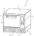
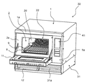
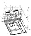
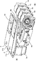
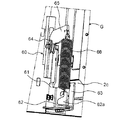
図1〜図4は、本開示の実施の形態1に係る加熱調理器30の外観を示す図である。図1は、扉11が閉じた状態における加熱調理器30の斜視図である。図2は、扉11が開いた状態における加熱調理器30の斜視図である。図3は、扉11が開いた状態における加熱調理器30の正面図である。図4は、扉11を取り外した状態において斜め下方から見た加熱調理器30の斜視図である。(Embodiment 1)
1-4 is a figure which shows the external appearance of the
本実施の形態に係る加熱調理器30は、特に、コンビニエンスストアやファーストフード店などで使用される業務用の電子レンジである。
The
図1〜図4に示すように、加熱調理器30は、外箱である本体1と、本体1を支持する機械室31と、本体1の前面1aに取り付けられた扉11とを備える。本体1の内側には、図2〜図4に示すように加熱室2が設けられる。加熱室2は、内部に被加熱物を収容するために、一つの面に開口が設けられた略直方体状の形状を有する筐体である。
As shown in FIGS. 1 to 4, the
以降の説明では、加熱室2の開口が設けられた側を加熱調理器30の前方、加熱室2の奥側を加熱調理器30の後方とそれぞれ定義し、加熱調理器30を前方から見た右側、左側をそれぞれ単に右側、左側という。
In the following description, the side where the opening of the
扉11は、加熱室2の開口を塞ぐように本体1の前面1aに取り付けられ、把手12の操作により扉11の両側下部に設けられたヒンジを中心に開閉可能である。扉11を閉じた状態(図1参照)で、加熱室2内の被加熱物にマイクロ波などによる加熱が行われ、扉11が開いた状態(図2参照)で、被加熱物が加熱室2に収容され、または、加熱室2から取り出される。
The
操作部41は、扉11の右隣の本体1の前面1aに設けられ、使用者が加熱調理器30を操作するためのボタンおよび表示画面を備える。
The
図2、図3に示すように、加熱室2内には、ステンレス製のワイヤラック(Wire rack)9と、セラミック(Ceramic)製(具体的にはコージライト(Cordierite)製)のトレイ(Tray)8とが設けられる。ワイヤラック9は、被加熱物を載置するために、網状の部材で構成された載置部である。トレイ8は、ワイヤラック9の下方に設けられ、ワイヤラック9上の被加熱物から滴り落ちる脂などを受ける。
As shown in FIGS. 2 and 3, the
図4に示すように、加熱室2内の天井2bの近傍にはグリルヒータ10が設けられる。グリルヒータ10は、屈曲した形状を有する一本のシーズヒータで構成され、輻射熱によって加熱室2の内部を加熱する。また、加熱室2内の天井2bには、加熱室2内の蒸気等を外部に排出するための排気孔46が設けられる。排気孔46には、図21、図22などを用いて後述する排気ダクト42(図示せず)が連結されている。
As shown in FIG. 4, a
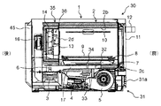
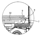
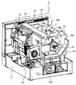
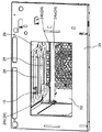
加熱調理器30の内部構造について、図5A、図5Bを用いて説明する。図5Aは、加熱調理器30の前後方向の縦断面図であり、図5Bは、図5Aの一部拡大断面図である。
The internal structure of the
図5A、図5Bに示すように、トレイ8は、皿受け台7上に載置される。皿受け台7は加熱室2の底面2cの上方に設けられ、トレイ8を支持する。本実施の形態では、皿受け台7はマイクロ波を透過可能なセラミック製の板で構成される。
As shown in FIGS. 5A and 5B, the
スタラ(Stirrer)32は、皿受け台7と加熱室2の底面2cとの間に設けられ、マイクロ波を撹拌するためにスタラ軸34を中心に回転する回転翼である。モータ33は機械室31内に設けられ、スタラ32を駆動する。
The
機械室31内には、マイクロ波を生成するマイクロ波生成部3と、マイクロ波生成部3を駆動するインバータ部4と、マイクロ波生成部3およびインバータ部4を冷却する冷却部5とが設けられる。
In the
マイクロ波生成部3は、後述するように二つのマグネトロンから構成され、加熱室2内に供給するマイクロ波を生成する。本実施の形態では、二つのマグネトロンの合計出力が1200W〜1300Wである。
As will be described later, the
導波管部17は、マイクロ波生成部3に連結され、加熱室2の底面2cの下方に底面2cに沿ってスタラ軸34まで延在するように設けられ、マイクロ波生成部3によって生成されたマイクロ波をスタラ軸34に導く。導波管部17は、後述するように二つの導波管から構成される。
The
導波管部17の上面には、スタラ軸34を通す孔(図示せず)が設けられ、その近傍にマイクロ波を放出するためのマイクロ波放射孔(図示せず)が設けられる。マイクロ波放射孔の詳細については後述する。
A hole (not shown) through which the
アンテナ6は、導波管部17内に設けられ、マイクロ波生成部3により生成されたマイクロ波をマイクロ波放射孔に向けて伝送する。アンテナ6により導波管部17内を伝送されるマイクロ波は、導波管部17に形成されたマイクロ波放射孔および底面2cに形成された開口(図示せず)を介して、加熱室2内に放射され、スタラ32によって撹拌される。
The
図5Aに示すように、インバータ部4は、マイクロ波生成部3の前方に配置され、マイクロ波生成部3を駆動する。インバータ部4は、後述するように二つのインバータから構成される。
As illustrated in FIG. 5A, the
冷却部5は、インバータ部4の前方に配置され、マイクロ波生成部3およびインバータ部4を冷却する。冷却部5は、後述するように四つの冷却ファンから構成される。
The
フロントグリル31aは、機械室31内に外気を取り込むための外気吸込口である。冷却部5は、機械室31のフロントグリル(Front grille)31aから外気を取り込んで後方に送ることにより、インバータ部4、マイクロ波生成部3を順に冷却する。
The
排気ダクト45は、本体1の後側に設けられ、インバータ部4、マイクロ波生成部3を冷却した後の空気を加熱調理器30の外部へ排気する。
The
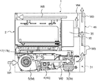
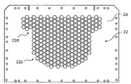
加熱室2内の奥壁2dには、複数の開口22(図2、図3参照)が形成されている。本実施の形態における開口22は、奥壁2dにパンチング(Punching)加工を行って形成した複数のパンチング孔である。奥壁2dの後方には、加熱室2内に供給する熱風を生成する対流装置35が設けられる。対流装置35は、奥壁2dによって加熱室2と区画され、開口22を介して加熱室2と連通する。
A plurality of openings 22 (see FIGS. 2 and 3) are formed in the
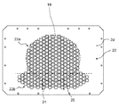
奥壁2dの正面図を図6に示す。図6に示すように、奥壁2dは略長方形状の金属板として形成されている。開口22は、奥壁2dの概ね中央部に一群のパンチング孔として形成された第1の孔と、第1の孔の下方に一群のパンチング孔として形成された第2の孔とを備える。第2の孔は、第1の孔より左右方向に広く分布するように形成されている。
A front view of the
後述するように、第1の孔が対流装置35への吸込口22aとして機能し、第2の孔が対流装置35からの吹出口22bとして機能する。
As will be described later, the first hole functions as an
一般的な対流オーブンにおけるパンチング孔の径が概ね5mmであるのに対して、本実施の形態における吸込口22aおよび吹出口22bの径はいずれも約2倍の10mmである。このような大きさとすることにより、開口22を通過する際の空気の圧力損失を最小限にしながら、開口22を通して加熱室2から対流装置35に漏れるマイクロ波の量を許容範囲内に抑えることができる。
While the diameter of the punching hole in a general convection oven is approximately 5 mm, the diameters of the
図5Aに示すように、対流装置35には、熱風を生成するための複数の部材で構成された熱風生成機構36が設けられる。熱風生成機構36は、加熱室2内の空気を対流装置35内に吸い込むとともに、対流装置35内の空気を加熱室2内に熱風として送出する。熱風生成機構36が熱風を加熱室2内に供給することで、熱風の循環流が加熱室2内に生じる。
As shown in FIG. 5A, the
上述した加熱調理器30の加熱構成によれば、加熱室2内に設けられたグリルヒータ10を用いた輻射による加熱と、マイクロ波生成部3を用いたマイクロ波加熱と、対流装置35の熱風生成機構36を用いた熱風の循環流による加熱とを別々にまたは同時に行うことが可能である。
According to the heating configuration of the
被加熱物の下方にヒータが配置されないので、被加熱物から滴り落ちる脂などの液体がヒータに接触することがなく、発煙や発火が起こることがない。なお、それぞれの加熱方法を組み合わせた加熱調理器30の具体的な運転方法の一例については後述する。
Since the heater is not disposed below the object to be heated, liquid such as oil dripping from the object to be heated does not come into contact with the heater, and smoke or ignition does not occur. In addition, an example of the specific operation method of the
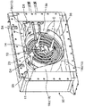
次に、対流装置35内の熱風生成機構36の構成について、図7〜図14Bを用いて説明する。
Next, the configuration of the hot
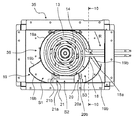
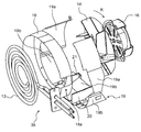
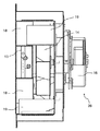
図7は、対流装置35の正面図である。図8は、対流装置35の斜視図である。図9は、対流装置35内の熱風生成機構36の分解斜視図である。図10は、図7の10−10断面図である。図11〜図14Bは、熱風生成機構36を構成する各部材の斜視図である。
FIG. 7 is a front view of the
図7〜図14Bに示すように、熱風生成機構36は、対流ヒータ13と、循環ファン14と、循環ファン14を駆動させるファン駆動部16(図9、図10参照)と、第1の風ガイドである風ガイド18と、第2の風ガイドである風ガイド19とを備える。
As shown in FIGS. 7 to 14B, the hot
対流ヒータ13は、グリルヒータ10とは別に対流装置35内に設けられ、対流装置35内の空気を加熱する。本実施の形態において、対流ヒータ13は、対流装置35の側方から延在する二本のシーズヒータで構成されており、空気との接触面積を増加させるために、対流装置35の中央部において渦巻き状に形成されている。
The
循環ファン14は、その中央部で空気を吸い込むとともに、吸い込んだ空気を遠心方向に送出する遠心ファンである。循環ファン14は、加熱室2内の空気を対流装置35内に吸い込み、対流装置35内の空気を加熱室2内に吹き出す。
The
循環ファン14は、対流ヒータ13の後方に設置されており、循環ファン14の後方に設置されたファン駆動部16によって駆動される。本実施の形態では、循環ファン14は矢印R(図7、図9参照)の方向へ回転するが、逆方向に回転しても良い。
The
風ガイド18は、循環ファン14によって対流装置35内に吸い込まれた空気が対流ヒータ13を通過するように導く部材であり、対流ヒータ13を取り囲むように配置されている。本実施の形態では、風ガイド18は略円筒形状に形成されている。風ガイド18には、内側にある対流ヒータ13を外側に延出させるための切欠き18aが形成されている。
The
風ガイド19は、循環ファン14によって送出される空気を導くための部材であり、循環ファン14を取り囲むように配置されている。本実施の形態では、風ガイド19は、風ガイド18の外側にて風ガイド18と部分的に接するように配置されている。
The
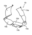
図14A、図14Bに示すように、風ガイド19は、風ガイド18の上側半分に対して外側から接合された接合部分19aと、風ガイド18から下方に離隔した離隔部分19bとから構成される。
As shown in FIGS. 14A and 14B, the
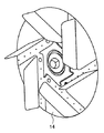
上記構成において、ファン駆動部16が循環ファン14を駆動させると、加熱室2内の空気が奥壁2dの吸込口22aを通して対流装置35内に吸い込まれる(図8の矢印C参照)。吸い込まれた空気は風ガイド18により対流ヒータ13に案内され、対流ヒータ13により加熱される。
In the above configuration, when the
循環ファン14は、対流ヒータ13によって加熱され、後方に向かう空気を渦巻き状に送出する。循環ファン14によって送出された空気は風ガイド19に導かれ、風ガイド18と風ガイド19の離隔部分19bとの間に形成された空間を流れる(矢印D1〜D3)。その後、その空気は、奥壁2dの吹出口22bを経由し、熱風として加熱室2内の下部に送出される。
The
すなわち、風ガイド18の内側には、吸込口22aから循環ファン14への空気の吸込経路が形成されて、風ガイド18と風ガイド19の離隔部分19bとの間には、循環ファン14から吹出口22bへの空気の吹出経路が形成される。このように、風ガイド18は、対流装置35における空気の吸込経路と吹出経路とを分離する案内板として機能する。
That is, an air suction path from the
風ガイド19の離隔部分19bには、第1の風向板である風向板20と第2の風向板である風向板21とが設けられる。風向板20、21は、循環ファン14によって渦巻き状に送出される熱風を前方に向けるように、前後方向に延在して、風ガイド18と風ガイド19の離隔部分19bとの間の空間を区画する。
A
図7に示すように、風向板20の下端20aおよび風向板21の下端21aはいずれも、風ガイド19の離隔部分19bの内側面に当接している。一方、風向板20の上端20bおよび風向板21の上端21bはいずれも、風ガイド18の外側面に当接している。
As shown in FIG. 7, the
風向板20、21の大きさについては、図14Aに示すように、風向板20が風向板21より、前後方向の長さおよび高さ方向の長さがいずれも大きくなるように構成されている。すなわち、風向板20の面積が風向板21の面積より大きい。
About the magnitude | size of the
図7、図8に示すように、風ガイド18と風ガイド19の離隔部分19bとの間の空間である吹出経路は、風向板20、21によって3つの空間(循環ファン14の回転方向Rにおける下流側から上流側に向かって順に空間S1、S2、S3)に区分される。通常、循環ファン14によって送出される熱風は、循環ファン14の回転方向Rの下流側にいくほど風が密集するため、風量が強くなる。
As shown in FIGS. 7 and 8, the blowout path, which is the space between the
しかしながら、本実施の形態によれば、前述したように風向板20は風向板21より大きいため、風ガイド18と風ガイド19との間の空間において、風向板20によって区画される空間S3に流れる熱風の風量を高めることができる。このような大きさの異なる風向板20、21によって吹出経路を空間S1〜S3に区画することにより、空間S1〜S3に流れる熱風D1〜D3(図8参照)の風量分布をより均一とすることができる。
However, according to the present embodiment, since the
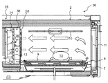
次に、上述した熱風生成機構36の給排気によって生じる加熱室2内の循環流の詳細について、図15を用いて説明する。
Next, details of the circulating flow in the
図15に示すように、対流装置35から吹出された熱風はワイヤラック9およびトレイ8に向かって流れる。被加熱物15を載置するワイヤラック9は、その下方側と上方側との間を空気が通過可能な、いわば通気性を有する構造であるため、熱風は被加熱物15の下方を通ることが可能となる。
As shown in FIG. 15, the hot air blown from the
被加熱物15の下方を通過する熱風は、上方にも抜けつつ、前方に向かって進む。前方に進んだ熱風はその後、扉11に当たり、扉11に沿って上方に向かう。その後、循環ファン14の吸引力によって、被加熱物15の上を通るようにして後方に流れる。最終的に、吸込口22aを通して対流装置35の中に吸い込まれる。
The hot air that passes under the article to be heated 15 advances forward while also passing upward. The hot air that has advanced forward then hits the
このような熱風の循環流によって被加熱物15の全面を加熱することができ、より均一な加熱を行うことができる。特に、被加熱物15の下方に熱風を供給しているため、一般的に加熱しにくいとされる被加熱物15の下面を効率的に加熱することができ、より均一に被加熱物15を加熱することができる。 The entire surface of the object to be heated 15 can be heated by such a circulating flow of hot air, and more uniform heating can be performed. In particular, since hot air is supplied below the object to be heated 15, the lower surface of the object to be heated 15 that is generally considered difficult to heat can be efficiently heated, and the object to be heated 15 can be more uniformly distributed. Can be heated.
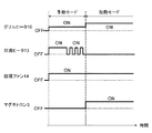
次に、加熱調理器30による加熱運転の一例について図16を用いて説明する。図16は、グリルヒータ10、対流ヒータ13、循環ファン14およびマイクロ波生成部3のON/OFFを示すタイミングチャートである。図16に示す例では、予熱モードを実施した後に加熱モードを実施することで、被加熱物15の加熱を行っている。
Next, an example of the heating operation by the
予熱モードは、加熱室2内に被加熱物15を配置しない状態にて、加熱モード前に加熱室2内を予め加熱するモードである。
The preheating mode is a mode in which the inside of the
予熱モードにおいては、グリルヒータ10をON状態で維持し、対流ヒータ13を最初しばらくON状態で維持した後、ONとOFFとを繰り返し、循環ファン14をON状態で維持し、マイクロ波生成部3をOFF状態で維持するように制御される。このような制御により、グリルヒータ10により加熱室2内全体を輻射加熱しながら、対流ヒータ13および循環ファン14によって加熱室2内に循環流を生じさせる。このようにして、加熱モードを開始する前に、加熱室2内全体を所定の温度まで均一に加熱する(例えば、230℃)。
In the preheating mode, the
加熱室2内の温度を図示しない温度センサにより継続的に測定している。対流ヒータ13は、加熱室2内の温度が予め定めた予熱設定温度(例えば、230℃)に達したときに、ON状態からON/OFF制御に切り換えられる。対流ヒータ13をON/OFF制御するのは、加熱室2内の温度を概ね予熱設定温度に維持するためである。
The temperature in the
循環ファン14を低速回転(例えば、2000rpm)させることで、加熱室2内の温度を均一にするとともに、循環ファン14のモータの寿命を延ばすことができる。
By rotating the
次に、加熱モードについて説明する。加熱モードは、予熱モードによって加熱された加熱室2内に被加熱物15を配置した状態で、被加熱物15をマイクロ波などによって加熱するモードである。
Next, the heating mode will be described. The heating mode is a mode in which the object to be heated 15 is heated by a microwave or the like in a state where the object to be heated 15 is disposed in the
加熱モードにおいては、グリルヒータ10の出力を上昇させ、対流ヒータ13をOFFし、循環ファン14を引き続きON状態で維持し、マイクロ波生成部3をONするように制御する。
In the heating mode, the output of the
これにより、グリルヒータ10により被加熱物15および加熱室2内全体を輻射加熱しながら、循環ファン14により加熱室2内に循環流を生じさせる。このように、輻射加熱と熱風の循環流による対流加熱とを組み合わせて、被加熱物15を均一に加熱する。
Thus, a circulating flow is generated in the
同時にマイクロ波生成部3を動作させ、輻射加熱および対流加熱に加えて、マイクロ波加熱をあわせて行う。高出力のマイクロ波生成部3を用いたマイクロ波加熱を行うことで、被加熱物15をより早く均一に加熱することができる。
At the same time, the
加熱モードにおいて、被加熱物15を早く加熱するために、グリルヒータ10の出力は加熱室2内の温度に応じて設定される。例えば、加熱室2内の温度が230度の場合にはグリルヒータ10の出力が350Wに設定され、加熱室2内の温度が150度の場合にはグリルヒータ10の出力が260Wに設定される。
In the heating mode, the output of the
対流ヒータ13をOFFするのは、加熱調理器30全体の消費電力を一定範囲内に制限するためである。例えば、一般的なコンセントは電流の上限が20Aという制約がある。そのため、マイクロ波生成部3を用いる加熱モードにおいては、対流ヒータ13をOFFすることで、上記電流の上限を超えないようにすることができる。
The reason why the
この場合でも、グリルヒータ10および循環ファン14はON状態を維持しているため、輻射加熱および対流加熱は継続される。
Even in this case, since the
なお、図16では、加熱モードにおける循環ファン14の回転数は予熱モードのときと同じであるが、これに限らず、被加熱物15の焼け具合をコントロールする目的で、約1500〜5000rpmの範囲で自由に設定することができる。
In FIG. 16, the rotational speed of the
上述したように、予熱モードと加熱モードとを組み合わせた加熱方法によれば、合計出力が約1300Wのマイクロ波生成部3を用いることで、例えば、被加熱物15として冷凍状態の半調理済みチキン四枚(100g〜150gほど)を約4分で解凍し加熱することができる。
As described above, according to the heating method in which the preheating mode and the heating mode are combined, by using the
以上のように、本実施の形態によれば、対流装置35において、風ガイド19により熱風が吹出口22bに導かれることにより、熱風を加熱室2の下部に集中して供給することが容易となる。その結果、被加熱物15をより早く均一に加熱することができる。
As described above, according to the present embodiment, in the
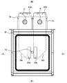
次に、上述した加熱運転と同時に行う本体1内におけるマイクロ波生成部3、ファン駆動部16のための冷却機構の構造、および、マイクロ波生成部3の二つのマグネトロンの配置について、図17〜図24を用いて説明する。
Next, the structure of the cooling mechanism for the
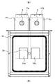
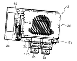
図17は、加熱室2の下方に設けられる二つのマグネトロン(マグネトロン3a、3b)および二つの導波管(導波管17a、17b)の配置を示すために、加熱室2の底面2cを上から見た平面図である。
FIG. 17 shows the
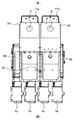
図18、図19はそれぞれ、機械室31における二つのマグネトロン、二つのインバータ(インバータ4a、4b)、二つの導波管および四つの冷却ファン(冷却ファン5a〜5d)の配置を示すための平面図、斜視図である。
FIGS. 18 and 19 are planes for illustrating the arrangement of two magnetrons, two inverters (
マグネトロン3a、3bは、左右に並んで配置される。マグネトロン3a、3bから延在する導波管17a、導波管17bも左右に並んで配置される。導波管17a、17bはともに、マグネトロン3a、3bから前方に向かって延在する。
導波管17a、17bの先端部に形成されるマイクロ波放射孔38aおよびマイクロ波放射孔38bは、加熱室2の底面2cの開口に連結された、加熱室2内へのマイクロ波の供給ポイントである。スタラ軸34は、マイクロ波放射孔38a、38bの間において加熱室2の底面2cを貫通する。
The
図18、図19に示すように、本実施の形態では、マグネトロン3a、3bに対してインバータ4a、4bがそれぞれ設けられ、マグネトロン3a、3bは、インバータ4a、4bによりそれぞれ別々に駆動される。
As shown in FIGS. 18 and 19, in the present embodiment,
マグネトロン3aおよびインバータ4aを冷却するために、冷却ファン5aと冷却ファン5bとが設けられ、マグネトロン3bおよびインバータ4bを冷却するために、冷却ファン5cと冷却ファン5dが設けられる。
A cooling
冷却ファン5a〜5dは、多翼ファンなどで構成され、インバータ4a、4bの前方にそれぞれの回転軸が一直線状に並ぶように設置され、ファンの回転軸の軸方向から空気を取り込み、加熱調理器30の後方に向けて空気を送り出すものである。各冷却ファンにおける空気の取り込みが隣接する冷却ファンによって阻害されないようにするために、冷却ファン5a〜5dは所定の間隔を設けて配置される。
The cooling
なお、マグネトロン3a、3bは、第1および第2マイクロ波生成部にそれぞれ対応する。導波管17a、17bは、第1および第2導波管にそれぞれ対応する。インバータ4a、4bは、第1および第2インバータにそれぞれ対応する。
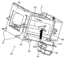
図20〜図22は、マイクロ波生成部3およびファン駆動部16のための冷却機構を説明するための図であり、これらの図には冷却機構による冷却風の流れが示されている。なお、図20〜図22では、説明のために本体1の前面1a以外を省略し、加熱室2を露出させて図示している。図23は、図4のA部拡大図であり、図24は、図21のE部拡大図である。
20-22 is a figure for demonstrating the cooling mechanism for the microwave production |
図20〜図22に示すように、冷却部5が作動すると、機械室31のフロントグリル31aから空気が吸い込まれるとともに(矢印W1参照)、冷却部5の後方に向かって空気が送出される(矢印W2参照)。送出された空気により、インバータ部4、マイクロ波生成部3が順に冷却される。
As shown in FIGS. 20 to 22, when the
インバータ部4、マイクロ波生成部3を冷却した空気は、本体1の背面に配置された排気ダクト45(図5A参照)を通って、加熱調理器30の上方へ排出される(矢印W3参照)。図21、図22では、排気ダクト45の図示を省略している。
The air that has cooled the
一方、ファン駆動部16用の冷却ファン43が作動すると、操作部41の後方に位置する本体1内の空間がファン駆動部16に向かって送出される。送出された空気は、仕切り部44(図21参照)によって上方に案内される(矢印W4)。上方に案内された空気は本体1の上面に当たり、本体1と加熱室2の間の空間を前方に向かって流れる(矢印W5参照)。
On the other hand, when the cooling
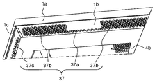
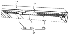
その後、本体1の前面1aの内側上面1bおよび内側側面1c(図23、図24参照)に形成された排気孔37から加熱調理器30の外へ排気される。排気孔37は、閉じられた状態の扉11の上面および側面と対向するように配置されている。
Thereafter, the air is exhausted out of the
上述した冷却機構によれば、冷却部5を用いてインバータ部4およびマイクロ波生成部3を冷却するとともに、冷却ファン43を用いてファン駆動部16を冷却している。このようにインバータ部4およびマイクロ波生成部3と、ファン駆動部16とを別々の冷却フローにより冷却することで、効率的な冷却を行うことができる。
According to the cooling mechanism described above, the
通常、加熱運転を行うと、マイクロ波生成部3の温度はインバータ部4の温度より高くなる。本実施の形態によれば、前述した冷却機構のように、温度の低い順にインバータ部4、マイクロ波生成部3を冷却することで、インバータ部4およびマイクロ波生成部3を効率的に冷却することができる。
Normally, when the heating operation is performed, the temperature of the
冷却ファン43により、本体1の内側空間を冷却風が絶えず流れるため、結果的に、加熱調理器30の上面および前面(本体1の上面および前面1a)の表面温度を低減する効果も有している。
Since the cooling air constantly flows in the inner space of the
また、ファン駆動部16を冷却して排気孔37から排気される空気が扉11の上面および側面に当たるよう構成されている。これにより、排気孔37が例えば本体1の前面1aに形成される場合と異なり、排気孔37から排出される空気が使用者に直接的に当たりにくくなるため、使用者の不快感を低減することができる。
Further, the
図23、図24に示すように、本体1の内側上面1bに形成された排気孔37のうち、中央部にある排気孔37aの数はその左右にある排気孔37bの数より少ない。このようにすることで、中央部からの排気量が少なくなる。
As shown in FIGS. 23 and 24, the number of the
これにより、使用者が扉11の中央上側に設けられた把手12を把持した際に、排気孔37から受ける排気の量を少なくすることができ、使用者の不快感を低減することができる。排気孔37a、37bに加え、内側側面1cにも排気孔37cを設けて排気する熱風を分散させることで、使用者の不快感をより低減することができる。
Thereby, when the user holds the
フロントグリル31aが加熱調理器30の前面側に設けられるため、左右に隣接して他の物体が存在するか否かにかかわらず、確実に空気を吸い込むことができる。これにより、例えば複数の加熱調理器30を左右に隣接して並べた場合でも、冷却風の吸込経路を確保することができる。
Since the
本実施の形態においては、図20に示すように、マイクロ波生成部3(マグネトロン3a、3b)が対流装置35の下方に配置され、冷却部5(冷却ファン5a〜5d)およびインバータ部4(インバータ4a、4b)が加熱室2の下方に配置される。
In this Embodiment, as shown in FIG. 20, the microwave production | generation part 3 (
また、図17〜図19に示すように、マグネトロン3aおよび導波管17aの組と、マグネトロン3bおよび導波管17bの組とが、左右に並べられ、導波管17a、17bが前後方向に延在するように配置される。
Further, as shown in FIGS. 17 to 19, the set of the
導波管17aの下方には、インバータ4aがマグネトロン3aと前後方向に並ぶように配置される。導波管17bの下方には、インバータ4bがマグネトロン3bと前後方向に並ぶにように配置される。インバータ4a、4bとは前後方向に並ぶように、かつ、それぞれのファンの回転軸が一直線状に並ぶように、冷却ファン5a〜5dが配置される。
An
上記構成により、機械室31内の空間を有効利用することができる。その結果、複数のマグネトロンを備えた加熱調理器30の横方向の寸法をより小さく設計することができる。コンビニエンスストアやファーストフード店などでは、複数の加熱調理器を左右に隣接して設置することが多いため、この効果は、特に、業務用の電子レンジにとって有意義である。
With the above configuration, the space in the
なお、加熱運転中に生成される加熱室2内の蒸気等は、図21、図22に示されるように、排気ダクト42を通って、本体1の後方部から上方へ排気される(矢印W6)。
In addition, the vapor | steam etc. in the
次に、扉11の開閉を支持するヒンジの構造について、図25〜図29を用いて説明する。
Next, the structure of the hinge that supports opening and closing of the
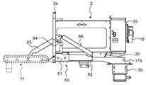
図25は、扉11が閉じられた状態(扉11は図示せず)の本体1内の側面図である。図26、図27Aは、扉11が閉じられた状態(扉11は図示せず)の本体1内の斜視図である。図27Bは図27Aにおける一点鎖線で囲われたG部の拡大図である。図28Aは図25の28A−28A断面図である。図28Bは図28Aにおける一点鎖線で囲われたH部の拡大図である。図29は、扉11が開けられた状態の本体1内の側面図である。
FIG. 25 is a side view of the inside of the
図25〜図29に示すように、加熱室2の側面と本体1の側面との間の左右の空間に一対のヒンジ構造60が設けられる。ヒンジ構造60は、ヒンジ61と、扉ヒンジスペーサ(Hinge spacer)62と、ヒンジ取付板63と、扉ガイドローラ(Guide roller)64と、扉アーム(Arm)65と、バネ66とを備える。
As shown in FIGS. 25 to 29, a pair of
図25、図26などに示すように、ヒンジ61は、加熱室2の前面2aを貫通し、扉ヒンジスペーサ62に固定されて、扉11の下端部を回転可能に支持する。図27A、図27Bなどに示すように、扉ヒンジスペーサ62には、ヒンジ61、ヒンジ取付板63およびバネ66が取り付けられる。
As shown in FIG. 25, FIG. 26, etc., the
扉ヒンジスペーサ62の後方側の端部には、バネ66を引っ掛けるためのフック(Hook)62aが設けられる。ヒンジ取付板63は、扉ヒンジスペーサ62および加熱室2の底面2cに固定され、扉ヒンジスペーサ62を介してヒンジ61を加熱室2の底面2cに固定する。
A
扉ガイドローラ64は、扉アーム65の前後方向の摺動を支持する。扉アーム65は、一端が扉11の中央部に取り付けられ、他端にはバネ66の一端が取り付けられて、ヒンジ61とともに扉11の開閉を支持する。バネ66の他端は、扉ヒンジスペーサ62のフック62aに固定されている。バネ66は、扉11が閉じられると縮み(図25参照)、扉11が開けられると伸びた状態となる(図29参照)。
The
上記構成において、ヒンジ61との連結点である下端部を中心として縦方向に回転することにより、扉11は、閉成状態から開成状態(図25から図29参照)に移行する。このとき、扉11の中央部に連結された扉アーム65は、扉ガイドローラ64上を摺動しながら前方に移動する。扉アーム65の移動により、扉アーム65の他端に取り付けられたバネ66は、縮んだ状態から伸びた状態となる。
In the above configuration, the
このようなヒンジ構造60の働きにより、扉11が開成される。反対に、扉11が開成状態から閉成状態(図29から図25参照)に移行する際には、前述の動作とは逆の動作が行われる。
The
本実施の形態では、ヒンジ61を含むヒンジ構造60は、ヒンジ取付板63によって、加熱室2の底面2cに取り付けられる。これとは異なり、ヒンジ61が加熱室2ではなく本体1に取り付けられる構成の場合、ヒンジ61の温度と加熱室2の前面2aの温度の差が大きくなる。そのため、扉11を閉じたときに、熱膨張率の差によりヒンジ61に取り付けられた扉11と加熱室2の前面2aとの間に隙間が生じる場合がある。
In the present embodiment, the
このような構成に比べて、本実施の形態のヒンジ構造60によれば、ヒンジ61が加熱室2の底面2cに取り付けられるため、ヒンジ61と加熱室2の前面2aとの温度差が小さくなる。これにより、扉11の閉成時に扉11と加熱室2の前面2aとの間に隙間が生じる可能性を低減することができる。
Compared to such a configuration, according to the
以上、上述の実施の形態を挙げて本開示を説明したが、本開示は上述の実施の形態に限定されない。本実施の形態では、導波管17a、17bがマグネトロン3a、3bから前方に向かって直線状に延在する場合について説明した。
Although the present disclosure has been described with reference to the above-described embodiment, the present disclosure is not limited to the above-described embodiment. In the present embodiment, the case where the
しかしながら、例えば、図30に示すように、導波管40a、導波管40bは、マイクロ波放射孔39a、マイクロ波放射孔39bに向かって90度湾曲したHコーナー形状39c、Hコーナー形状39dを有してもよい。
However, for example, as shown in FIG. 30, the
「Eコーナー形状」が、導波管を電界面(E面)と平行に曲げる形状であるのに対して、「Hコーナー形状」は、導波管40a、40bを磁界面(H面)と平行に曲げる形状である。導波管40a、40bがHコーナー形状39c、39dにてマイクロ波放射孔39a、39bにつながることにより、進行方向を90度曲げられたマイクロ波同士が加熱室2の中央付近で重なり、より強度の高いマイクロ波を放射することができる。
The “E corner shape” is a shape in which the waveguide is bent parallel to the electric field surface (E surface), whereas the “H corner shape” is the
(実施の形態2)
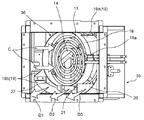
以下、本開示の実施の形態2に係る加熱装置について、図31〜図33を用いて説明する。図31は、実施の形態2における対流装置50の斜視図である。図32は、本開示の実施の形態2における加熱室2の奥壁2dの正面図である。(Embodiment 2)
Hereinafter, the heating apparatus according to the second embodiment of the present disclosure will be described with reference to FIGS. FIG. 31 is a perspective view of the
本実施の形態においても実施の形態1と同様に、加熱室2の奥壁2dの後方に、加熱室2内に供給する熱風を生成する対流装置50が設けられる。対流装置50は、奥壁2dによって加熱室2と区画され、開口22を介して加熱室2と連通する。
Also in the present embodiment, as in the first embodiment, a
しかしながら、図31に示すように、本実施の形態では、風ガイド19の接合部分19cと離隔部分19dとの上下の位置関係が実施の形態1とは逆になっている。すなわち、風ガイド19の離隔部分19dは、風ガイド18の上側半分において風ガイド18から離隔するように設けられる。
However, as shown in FIG. 31, in the present embodiment, the vertical positional relationship between the
これに伴い、本実施の形態では、奥壁2dの概ね中央部に形成された吸込口22cの上方に、吹出口22dが設けられる(図32参照)。
In connection with this, in this Embodiment, the
また、実施の形態1では、風ガイド19は風ガイド18とは別部材で構成されるのに対して、本実施の形態では、風ガイド19の接合部分19cは風ガイド18と、いわば一体的に構成される。
In the first embodiment, the
さらに、実施の形態1では、風ガイド18と風ガイド19との間に前後方向に二つの風向板(風向板20、21)が設けられるのに対して、本実施の形態では、風ガイド18と風ガイド19との間に前後方向に一つの風向板(風向板23)が設けられる。
Furthermore, in the first embodiment, two wind direction plates (
風向板23は、風向板20、21と同様に、風ガイド18と風ガイド19の離隔部分19dとの間の空間を区画し、循環ファン14により渦巻き状に送出される熱風を前方向に向かわせる。
The
上記構成において、循環ファン14が駆動されると、加熱室2内の空気が奥壁2dの吸込口22aを通して対流装置50内に吸い込まれる(図31の矢印C参照)。吸い込まれた空気は風ガイド18により循環ファン14に向かって流れる。
In the above configuration, when the
循環ファン14によって送出された空気は、風ガイド19に導かれ、風ガイド18と風ガイド19の離隔部分19dとの間に形成された空間を流れる(矢印D4、D5)。その後、その空気は、奥壁2dの吹出口22bを経由して、加熱室2の天井近傍に送出される。
The air sent out by the
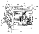
図33は、実施の形態2に係る加熱室2の内部、特に天井を示す斜視図である。図33に示すように、本実施の形態では、奥壁2dの吸込口22cと吹出口22dとの境目付近に、前方に突出する風向板24が設けられる。風向板24は、加熱室2を左右方向に横切るように水平方向に延在する水平部分24aと、水平部分24aの上方に、所定の間隔で垂直方向に延在する垂直部分24bおよび垂直部分24cとを有する。
FIG. 33 is a perspective view showing the inside of the
風向板24は、対流装置35から加熱室2内に供給された空気の流れに指向性を与え、その空気の流れの大半をグリルヒータ10の方向に向かわせる。
The
グリルヒータ10の近傍(より具体的には、屈曲したグリルヒータ10の間)に位置するように、加熱室2の天井2bに、左右方向に延在する二つの風向板(風向板25、26)が設けられる。風向板26の幅は、風向板26より後方に位置する風向板25の幅より広い。
Two wind direction plates (
風向板25、26は、加熱室2の天井の中央付近で、対流装置35から送出された空気の流れの一部を下方に向ける。
The
上記構成により、対流装置35により送出され、対流ヒータ13および/またはグリルヒータ10により加熱された熱風の循環流の一部は、被加熱物15に上方から吹き付け、被加熱物15を加熱する。このようにして、被加熱物15をより早く均一に加熱することができる。
With the above configuration, a part of the circulating hot air sent from the
本開示は、グリルモードと対流モードとを有する電子レンジに適用可能であり、特にコンビニエンスストアやファーストフード店などで使用される業務用の電子レンジにとって有用である。 The present disclosure is applicable to a microwave oven having a grill mode and a convection mode, and is particularly useful for a commercial microwave oven used in a convenience store or a fast food store.
1 本体
1a,2a 前面
2 加熱室
2b 天井
2c 底面
2d 奥壁
3 マイクロ波生成部
3a,3b マグネトロン
4 インバータ部
4a,4b インバータ
5 冷却部
5a,5b,5c,5d,43 冷却ファン
6 アンテナ
7 皿受け台
8 トレイ
9 ワイヤラック
10 グリルヒータ
11 扉
12 把手
13 対流ヒータ
14 循環ファン
15 被加熱物
16 ファン駆動部
17 導波管部
17a,17b,40a,40b 導波管
18,19 風ガイド
18a 切欠き
19a,19c 接合部分
19b,19d 離隔部分
20,21,23,24,25,26 風向板
20a,21a 下端
20b,21b 上端
22 開口
22a,22c 吸込口
22b,22d 吹出口
24a 水平部分
24b,24c 垂直部分
30 加熱調理器
31 機械室
31a フロントグリル
32 スタラ
33 モータ
34 スタラ軸
35,50 対流装置
36 熱風生成機構
37,37a,37b,37c 排気孔
38a,38b,39a,39b マイクロ波放射孔
39c,39d Hコーナー形状
41 操作部
42 排気ダクト
44 仕切り部
45 排気ダクト
46 排気孔
60 ヒンジ構造
61 ヒンジ
62 扉ヒンジスペーサ
62a フック
63 ヒンジ取付板
64 扉ガイドローラ
65 扉アーム
66 バネDESCRIPTION OF
Claims (10)
前記加熱室の奥壁の後方に設けられ、前記加熱室の奥壁に設けられた吸込口と吹出口とを介して加熱室と連通し、熱風を生成して前記加熱室に供給する対流装置であって、
前記加熱室内の空気を前記吸込口から前記対流装置に吸い込み、吸い込まれた空気を前記吹出口から前記加熱室内に送出する循環ファンと、
前記循環ファンの前方に設けられ、前記対流装置に吸い込まれた空気を加熱する対流ヒータと、
前記対流ヒータを取り囲むように設けられ、前記対流装置に吸い込まれた空気を前記対流ヒータに導く第1の風ガイドと、
前記循環ファンと前記第1の風ガイドとを取り囲むように設けられ、前記対流ヒータにより加熱された空気を前記吹出口に導く第2の風ガイドと、を有する対流装置と、
を備え、
前記第2の風ガイドの一部分が前記第1の風ガイドと接し、前記第2の風ガイドの他の一部分が前記第1の風ガイドから離隔するように構成された、加熱調理器。A heating chamber for storing an object to be heated;
A convection device that is provided behind the back wall of the heating chamber, communicates with the heating chamber via a suction port and a blowout port provided on the back wall of the heating chamber, generates hot air, and supplies the hot air to the heating chamber Because
A circulation fan for sucking the air in the heating chamber from the suction port into the convection device and sending the sucked air into the heating chamber from the air outlet;
A convection heater that is provided in front of the circulation fan and that heats the air drawn into the convection device;
A first wind guide provided so as to surround the convection heater and guiding the air sucked into the convection device to the convection heater;
A convection device having a second wind guide provided so as to surround the circulation fan and the first wind guide and guiding the air heated by the convection heater to the outlet;
With
A heating cooker configured such that a part of the second wind guide is in contact with the first wind guide and the other part of the second wind guide is separated from the first wind guide.
前記第2の風ガイドは、前記循環ファンから送出された空気を前記載置部と前記加熱室の底面との間に導くように構成された、請求項1に記載の加熱調理器。It further has a breathability, and further includes a placement portion for placing the object to be heated in the heating chamber,
2. The cooking device according to claim 1, wherein the second wind guide is configured to guide the air sent from the circulation fan between the placement unit and the bottom surface of the heating chamber.
前記マイクロ波を前記加熱室に導く導波管と、をさらに備えた、請求項1に記載の加熱調理器。A microwave generator for generating microwaves;
The heating cooker according to claim 1, further comprising a waveguide that guides the microwave to the heating chamber.
Applications Claiming Priority (3)
| Application Number | Priority Date | Filing Date | Title |
|---|---|---|---|
| JP2014020427 | 2014-02-05 | ||
| JP2014020427 | 2014-02-05 | ||
| PCT/JP2015/000509 WO2015118867A1 (en) | 2014-02-05 | 2015-02-05 | Heat cooker |
Publications (2)
| Publication Number | Publication Date |
|---|---|
| JPWO2015118867A1 JPWO2015118867A1 (en) | 2017-03-23 |
| JP6263745B2 true JP6263745B2 (en) | 2018-01-24 |
Family
ID=53777679
Family Applications (1)
| Application Number | Title | Priority Date | Filing Date |
|---|---|---|---|
| JP2015561220A Active JP6263745B2 (en) | 2014-02-05 | 2015-02-05 | Cooker |
Country Status (5)
| Country | Link |
|---|---|
| US (1) | US10368403B2 (en) |
| EP (1) | EP3104083B1 (en) |
| JP (1) | JP6263745B2 (en) |
| CN (1) | CN105940267B (en) |
| WO (1) | WO2015118867A1 (en) |
Families Citing this family (17)
| Publication number | Priority date | Publication date | Assignee | Title |
|---|---|---|---|---|
| US10415836B2 (en) * | 2015-02-06 | 2019-09-17 | Michael James McIntyre | Cooking apparatus and air delivery and circulation device therefore |
| CA2988528C (en) * | 2015-08-26 | 2019-04-02 | Panasonic Intellectual Property Management Co., Ltd. | Cooker |
| WO2017038021A1 (en) | 2015-09-02 | 2017-03-09 | パナソニックIpマネジメント株式会社 | Cooking apparatus |
| JP6948857B2 (en) * | 2017-07-12 | 2021-10-13 | リンナイ株式会社 | Cooker |
| CN110123159A (en) | 2017-08-09 | 2019-08-16 | 沙克忍者运营有限责任公司 | Cooking system |
| KR102401514B1 (en) | 2017-10-25 | 2022-05-25 | 삼성전자주식회사 | Oven |
| JP7149501B2 (en) | 2019-01-10 | 2022-10-07 | パナソニックIpマネジメント株式会社 | heating cooker |
| US20190254476A1 (en) | 2019-02-25 | 2019-08-22 | Sharkninja Operating Llc | Cooking device and components thereof |
| CN212788226U (en) | 2019-02-25 | 2021-03-26 | 沙克忍者运营有限责任公司 | cooking system |
| CN212346260U (en) | 2019-02-26 | 2021-01-15 | 沙克忍者运营有限责任公司 | Cooking system capable of being positioned on a support surface and mountable cooking system |
| EP4006420B1 (en) * | 2019-07-31 | 2026-04-22 | Sharp Kabushiki Kaisha | Heating cooker |
| CA3151895A1 (en) * | 2019-08-20 | 2021-02-25 | Sharp Kabushiki Kaisha | Pull-out heating cooking apparatus |
| US11647861B2 (en) | 2020-03-30 | 2023-05-16 | Sharkninja Operating Llc | Cooking device and components thereof |
| CN113491454B (en) | 2020-04-06 | 2026-04-14 | 尚科宁家运营有限公司 | Cooking system positionable on a support surface |
| TW202323732A (en) * | 2021-10-04 | 2023-06-16 | 日商松下知識產權經營股份有限公司 | Heating cooker |
| JP7607198B2 (en) * | 2021-10-04 | 2024-12-27 | パナソニックIpマネジメント株式会社 | Cooking equipment |
| US11882961B1 (en) | 2023-01-18 | 2024-01-30 | Sharkninja Operating Llc | Cover plate for cooking devices |
Family Cites Families (17)
| Publication number | Priority date | Publication date | Assignee | Title |
|---|---|---|---|---|
| US4780596A (en) * | 1986-05-15 | 1988-10-25 | Kabushiki Kaisha Toshiba | Hot-air circulation cooking oven |
| JPS62268921A (en) * | 1986-05-15 | 1987-11-21 | Toshiba Corp | Hot air circulating type cooker |
| US4745249A (en) * | 1987-02-19 | 1988-05-17 | Mrs. Paul's Kitchens Inc. | Package and method for microwave heating of a food product |
| JPH01169701U (en) * | 1988-05-20 | 1989-11-30 | ||
| JPH0634137A (en) | 1992-07-21 | 1994-02-08 | Sanyo Electric Co Ltd | Microwave oven |
| JPH08327065A (en) * | 1995-05-29 | 1996-12-10 | Toshiba Corp | Heating cooker |
| US5756974A (en) * | 1995-06-09 | 1998-05-26 | Samsung Electronics Co., Ltd. | Convection microwave oven having improved hot air circulation |
| DE19963294C5 (en) * | 1999-12-27 | 2004-06-03 | Convotherm Elektrogeräte GmbH | Cooking appliance |
| JP3935726B2 (en) * | 2002-01-11 | 2007-06-27 | シャープ株式会社 | Cooker |
| JP3835804B2 (en) * | 2004-02-10 | 2006-10-18 | 松下電器産業株式会社 | Cooking device and cooking method |
| JP2005315487A (en) * | 2004-04-28 | 2005-11-10 | Matsushita Electric Ind Co Ltd | Microwave heating method and apparatus |
| KR20060006472A (en) * | 2004-07-16 | 2006-01-19 | 삼성전자주식회사 | Heating cooker |
| JP2006170579A (en) * | 2004-12-20 | 2006-06-29 | Hitachi Home & Life Solutions Inc | Cooker |
| JP2007003121A (en) * | 2005-06-24 | 2007-01-11 | Toshiba Corp | Cooker |
| KR100735183B1 (en) * | 2005-12-28 | 2007-07-03 | 엘지전자 주식회사 | Electric oven |
| JP2010054173A (en) | 2008-08-29 | 2010-03-11 | Sharp Corp | Cooker |
| JP5015287B2 (en) * | 2010-05-11 | 2012-08-29 | シャープ株式会社 | Cooker |
-
2015
- 2015-02-05 CN CN201580006757.4A patent/CN105940267B/en not_active Expired - Fee Related
- 2015-02-05 JP JP2015561220A patent/JP6263745B2/en active Active
- 2015-02-05 EP EP15746402.5A patent/EP3104083B1/en active Active
- 2015-02-05 WO PCT/JP2015/000509 patent/WO2015118867A1/en not_active Ceased
- 2015-02-05 US US15/109,818 patent/US10368403B2/en active Active
Also Published As
| Publication number | Publication date |
|---|---|
| EP3104083A1 (en) | 2016-12-14 |
| CN105940267B (en) | 2018-04-24 |
| US20160330801A1 (en) | 2016-11-10 |
| EP3104083B1 (en) | 2018-05-23 |
| CN105940267A (en) | 2016-09-14 |
| US10368403B2 (en) | 2019-07-30 |
| EP3104083A4 (en) | 2017-01-25 |
| WO2015118867A1 (en) | 2015-08-13 |
| JPWO2015118867A1 (en) | 2017-03-23 |
Similar Documents
| Publication | Publication Date | Title |
|---|---|---|
| JP6263745B2 (en) | Cooker | |
| JP6402367B2 (en) | Microwave heating device | |
| JP6898140B2 (en) | Cooker | |
| JP6782400B2 (en) | Cooker | |
| JP2002206748A (en) | Heating apparatus for microwave oven | |
| JP6131717B2 (en) | Cooker | |
| JP6382153B2 (en) | Cooker | |
| US7345261B2 (en) | Wall-mounted microwave oven | |
| JP2007003042A (en) | Cooker | |
| JP2015203518A (en) | Cooker | |
| JP6472710B2 (en) | Cooker | |
| JP6491973B2 (en) | Cooker | |
| JP6114920B2 (en) | Cooker | |
| JP2011080710A (en) | Heating device | |
| JP2010243116A (en) | Cooker | |
| KR200349518Y1 (en) | A structure of chamber cover in Electric oven | |
| JP5119881B2 (en) | Cooking machine | |
| JP2013165820A (en) | Rack for cooking and cooker | |
| JP2007010163A (en) | Cooker | |
| JP2010249364A (en) | Cooker | |
| JP2011080709A (en) | Heating device | |
| JP2005233522A (en) | Cooker | |
| HK1242405B (en) | Cooker |
Legal Events
| Date | Code | Title | Description |
|---|---|---|---|
| A621 | Written request for application examination |
Free format text: JAPANESE INTERMEDIATE CODE: A621 Effective date: 20170123 |
|
| TRDD | Decision of grant or rejection written | ||
| A01 | Written decision to grant a patent or to grant a registration (utility model) |
Free format text: JAPANESE INTERMEDIATE CODE: A01 Effective date: 20171107 |
|
| A61 | First payment of annual fees (during grant procedure) |
Free format text: JAPANESE INTERMEDIATE CODE: A61 Effective date: 20171120 |
|
| R151 | Written notification of patent or utility model registration |
Ref document number: 6263745 Country of ref document: JP Free format text: JAPANESE INTERMEDIATE CODE: R151 |