CN113648067A - System and method for illumination and imaging of an object - Google Patents
System and method for illumination and imaging of an object Download PDFInfo
- Publication number
- CN113648067A CN113648067A CN202110658728.3A CN202110658728A CN113648067A CN 113648067 A CN113648067 A CN 113648067A CN 202110658728 A CN202110658728 A CN 202110658728A CN 113648067 A CN113648067 A CN 113648067A
- Authority
- CN
- China
- Prior art keywords
- illumination
- imaging
- fluorescence
- target
- light
- Prior art date
- Legal status (The legal status is an assumption and is not a legal conclusion. Google has not performed a legal analysis and makes no representation as to the accuracy of the status listed.)
- Pending
Links
- 238000003384 imaging method Methods 0.000 title claims abstract description 177
- 238000005286 illumination Methods 0.000 title claims description 242
- 238000000034 method Methods 0.000 title claims description 56
- 230000005284 excitation Effects 0.000 claims abstract description 76
- 239000000463 material Substances 0.000 claims abstract description 16
- 230000001681 protective effect Effects 0.000 claims abstract 6
- 230000001419 dependent effect Effects 0.000 claims description 14
- 102100029091 Exportin-2 Human genes 0.000 claims description 10
- 101710147878 Exportin-2 Proteins 0.000 claims description 10
- 102100029095 Exportin-1 Human genes 0.000 claims description 8
- 108700002148 exportin 1 Proteins 0.000 claims description 8
- 238000011144 upstream manufacturing Methods 0.000 claims description 3
- 239000012216 imaging agent Substances 0.000 description 60
- 238000000799 fluorescence microscopy Methods 0.000 description 36
- 210000001519 tissue Anatomy 0.000 description 26
- 238000012632 fluorescent imaging Methods 0.000 description 25
- 238000009826 distribution Methods 0.000 description 24
- 230000003287 optical effect Effects 0.000 description 21
- 210000004369 blood Anatomy 0.000 description 18
- 239000008280 blood Substances 0.000 description 18
- 230000005540 biological transmission Effects 0.000 description 14
- 238000010586 diagram Methods 0.000 description 14
- 238000002073 fluorescence micrograph Methods 0.000 description 12
- 239000007850 fluorescent dye Substances 0.000 description 12
- 229960004657 indocyanine green Drugs 0.000 description 12
- MOFVSTNWEDAEEK-UHFFFAOYSA-M indocyanine green Chemical compound [Na+].[O-]S(=O)(=O)CCCCN1C2=CC=C3C=CC=CC3=C2C(C)(C)C1=CC=CC=CC=CC1=[N+](CCCCS([O-])(=O)=O)C2=CC=C(C=CC=C3)C3=C2C1(C)C MOFVSTNWEDAEEK-UHFFFAOYSA-M 0.000 description 12
- 230000033001 locomotion Effects 0.000 description 10
- 210000003484 anatomy Anatomy 0.000 description 9
- 238000002059 diagnostic imaging Methods 0.000 description 9
- 210000002751 lymph Anatomy 0.000 description 8
- 238000012977 invasive surgical procedure Methods 0.000 description 7
- 230000017531 blood circulation Effects 0.000 description 6
- 210000004204 blood vessel Anatomy 0.000 description 6
- 230000010412 perfusion Effects 0.000 description 6
- 238000005259 measurement Methods 0.000 description 5
- 238000001356 surgical procedure Methods 0.000 description 5
- 230000000747 cardiac effect Effects 0.000 description 4
- 238000013461 design Methods 0.000 description 4
- 239000003085 diluting agent Substances 0.000 description 4
- 210000001165 lymph node Anatomy 0.000 description 4
- 238000002620 method output Methods 0.000 description 4
- 230000001360 synchronised effect Effects 0.000 description 4
- HEMHJVSKTPXQMS-UHFFFAOYSA-M Sodium hydroxide Chemical compound [OH-].[Na+] HEMHJVSKTPXQMS-UHFFFAOYSA-M 0.000 description 3
- 206010052428 Wound Diseases 0.000 description 3
- 208000027418 Wounds and injury Diseases 0.000 description 3
- 238000010521 absorption reaction Methods 0.000 description 3
- 238000004891 communication Methods 0.000 description 3
- 239000000975 dye Substances 0.000 description 3
- 239000000835 fiber Substances 0.000 description 3
- 230000006870 function Effects 0.000 description 3
- 238000012986 modification Methods 0.000 description 3
- 230000004048 modification Effects 0.000 description 3
- 238000010606 normalization Methods 0.000 description 3
- 238000012545 processing Methods 0.000 description 3
- 239000007787 solid Substances 0.000 description 3
- 238000003860 storage Methods 0.000 description 3
- 230000004913 activation Effects 0.000 description 2
- 239000012620 biological material Substances 0.000 description 2
- 230000008081 blood perfusion Effects 0.000 description 2
- 239000003795 chemical substances by application Substances 0.000 description 2
- 238000013500 data storage Methods 0.000 description 2
- 230000000694 effects Effects 0.000 description 2
- 210000004996 female reproductive system Anatomy 0.000 description 2
- 210000003811 finger Anatomy 0.000 description 2
- 230000000670 limiting effect Effects 0.000 description 2
- 238000007726 management method Methods 0.000 description 2
- 239000012528 membrane Substances 0.000 description 2
- 238000012978 minimally invasive surgical procedure Methods 0.000 description 2
- 230000000050 nutritive effect Effects 0.000 description 2
- 230000008569 process Effects 0.000 description 2
- 238000012079 reconstructive surgical procedure Methods 0.000 description 2
- 238000001454 recorded image Methods 0.000 description 2
- 238000005096 rolling process Methods 0.000 description 2
- 238000011410 subtraction method Methods 0.000 description 2
- 239000013077 target material Substances 0.000 description 2
- 230000008685 targeting Effects 0.000 description 2
- 210000003813 thumb Anatomy 0.000 description 2
- 210000005166 vasculature Anatomy 0.000 description 2
- 238000012800 visualization Methods 0.000 description 2
- 239000002699 waste material Substances 0.000 description 2
- JKMHFZQWWAIEOD-UHFFFAOYSA-N 2-[4-(2-hydroxyethyl)piperazin-1-yl]ethanesulfonic acid Chemical compound OCC[NH+]1CCN(CCS([O-])(=O)=O)CC1 JKMHFZQWWAIEOD-UHFFFAOYSA-N 0.000 description 1
- RBTBFTRPCNLSDE-UHFFFAOYSA-N 3,7-bis(dimethylamino)phenothiazin-5-ium Chemical compound C1=CC(N(C)C)=CC2=[S+]C3=CC(N(C)C)=CC=C3N=C21 RBTBFTRPCNLSDE-UHFFFAOYSA-N 0.000 description 1
- IICCLYANAQEHCI-UHFFFAOYSA-N 4,5,6,7-tetrachloro-3',6'-dihydroxy-2',4',5',7'-tetraiodospiro[2-benzofuran-3,9'-xanthene]-1-one Chemical compound O1C(=O)C(C(=C(Cl)C(Cl)=C2Cl)Cl)=C2C21C1=CC(I)=C(O)C(I)=C1OC1=C(I)C(O)=C(I)C=C21 IICCLYANAQEHCI-UHFFFAOYSA-N 0.000 description 1
- 102000004506 Blood Proteins Human genes 0.000 description 1
- 108010017384 Blood Proteins Proteins 0.000 description 1
- 206010011985 Decubitus ulcer Diseases 0.000 description 1
- 239000007995 HEPES buffer Substances 0.000 description 1
- 102000004895 Lipoproteins Human genes 0.000 description 1
- 108090001030 Lipoproteins Proteins 0.000 description 1
- 108010053210 Phycocyanin Proteins 0.000 description 1
- 108010004729 Phycoerythrin Proteins 0.000 description 1
- 208000004210 Pressure Ulcer Diseases 0.000 description 1
- 239000007983 Tris buffer Substances 0.000 description 1
- GLNADSQYFUSGOU-GPTZEZBUSA-J Trypan blue Chemical compound [Na+].[Na+].[Na+].[Na+].C1=C(S([O-])(=O)=O)C=C2C=C(S([O-])(=O)=O)C(/N=N/C3=CC=C(C=C3C)C=3C=C(C(=CC=3)\N=N\C=3C(=CC4=CC(=CC(N)=C4C=3O)S([O-])(=O)=O)S([O-])(=O)=O)C)=C(O)C2=C1N GLNADSQYFUSGOU-GPTZEZBUSA-J 0.000 description 1
- 230000002411 adverse Effects 0.000 description 1
- 108010004469 allophycocyanin Proteins 0.000 description 1
- 150000001413 amino acids Chemical class 0.000 description 1
- 230000003321 amplification Effects 0.000 description 1
- 210000002565 arteriole Anatomy 0.000 description 1
- 210000001367 artery Anatomy 0.000 description 1
- QVGXLLKOCUKJST-UHFFFAOYSA-N atomic oxygen Chemical compound [O] QVGXLLKOCUKJST-UHFFFAOYSA-N 0.000 description 1
- 230000002238 attenuated effect Effects 0.000 description 1
- 230000000903 blocking effect Effects 0.000 description 1
- 239000000872 buffer Substances 0.000 description 1
- 210000001736 capillary Anatomy 0.000 description 1
- 239000000969 carrier Substances 0.000 description 1
- 230000009087 cell motility Effects 0.000 description 1
- 210000003679 cervix uteri Anatomy 0.000 description 1
- 230000001684 chronic effect Effects 0.000 description 1
- 230000004087 circulation Effects 0.000 description 1
- 210000004351 coronary vessel Anatomy 0.000 description 1
- 230000003247 decreasing effect Effects 0.000 description 1
- 230000008021 deposition Effects 0.000 description 1
- 230000000881 depressing effect Effects 0.000 description 1
- 238000001514 detection method Methods 0.000 description 1
- 238000005516 engineering process Methods 0.000 description 1
- 210000003743 erythrocyte Anatomy 0.000 description 1
- 239000012530 fluid Substances 0.000 description 1
- ZFKJVJIDPQDDFY-UHFFFAOYSA-N fluorescamine Chemical compound C12=CC=CC=C2C(=O)OC1(C1=O)OC=C1C1=CC=CC=C1 ZFKJVJIDPQDDFY-UHFFFAOYSA-N 0.000 description 1
- MHMNJMPURVTYEJ-UHFFFAOYSA-N fluorescein-5-isothiocyanate Chemical compound O1C(=O)C2=CC(N=C=S)=CC=C2C21C1=CC=C(O)C=C1OC1=CC(O)=CC=C21 MHMNJMPURVTYEJ-UHFFFAOYSA-N 0.000 description 1
- DVGHHMFBFOTGLM-UHFFFAOYSA-L fluorogold Chemical compound F[Au][Au]F DVGHHMFBFOTGLM-UHFFFAOYSA-L 0.000 description 1
- 230000004907 flux Effects 0.000 description 1
- 210000005224 forefinger Anatomy 0.000 description 1
- 239000011521 glass Substances 0.000 description 1
- 239000005337 ground glass Substances 0.000 description 1
- 238000002329 infrared spectrum Methods 0.000 description 1
- 238000002347 injection Methods 0.000 description 1
- 239000007924 injection Substances 0.000 description 1
- 238000002955 isolation Methods 0.000 description 1
- 239000007788 liquid Substances 0.000 description 1
- 230000001926 lymphatic effect Effects 0.000 description 1
- 239000008176 lyophilized powder Substances 0.000 description 1
- 230000007246 mechanism Effects 0.000 description 1
- 239000002207 metabolite Substances 0.000 description 1
- 229960000907 methylthioninium chloride Drugs 0.000 description 1
- 230000004089 microcirculation Effects 0.000 description 1
- 210000004088 microvessel Anatomy 0.000 description 1
- 238000002324 minimally invasive surgery Methods 0.000 description 1
- 231100000252 nontoxic Toxicity 0.000 description 1
- 230000003000 nontoxic effect Effects 0.000 description 1
- 238000003199 nucleic acid amplification method Methods 0.000 description 1
- 235000015097 nutrients Nutrition 0.000 description 1
- 239000013307 optical fiber Substances 0.000 description 1
- 239000005304 optical glass Substances 0.000 description 1
- 238000012634 optical imaging Methods 0.000 description 1
- 230000010355 oscillation Effects 0.000 description 1
- 229910052760 oxygen Inorganic materials 0.000 description 1
- 239000001301 oxygen Substances 0.000 description 1
- 230000036961 partial effect Effects 0.000 description 1
- 239000002245 particle Substances 0.000 description 1
- 239000008363 phosphate buffer Substances 0.000 description 1
- ZWLUXSQADUDCSB-UHFFFAOYSA-N phthalaldehyde Chemical compound O=CC1=CC=CC=C1C=O ZWLUXSQADUDCSB-UHFFFAOYSA-N 0.000 description 1
- 108090000765 processed proteins & peptides Proteins 0.000 description 1
- 102000004169 proteins and genes Human genes 0.000 description 1
- 108090000623 proteins and genes Proteins 0.000 description 1
- 230000010349 pulsation Effects 0.000 description 1
- 210000001747 pupil Anatomy 0.000 description 1
- 238000011002 quantification Methods 0.000 description 1
- 238000010791 quenching Methods 0.000 description 1
- 230000002829 reductive effect Effects 0.000 description 1
- 238000012552 review Methods 0.000 description 1
- PYWVYCXTNDRMGF-UHFFFAOYSA-N rhodamine B Chemical compound [Cl-].C=12C=CC(=[N+](CC)CC)C=C2OC2=CC(N(CC)CC)=CC=C2C=1C1=CC=CC=C1C(O)=O PYWVYCXTNDRMGF-UHFFFAOYSA-N 0.000 description 1
- 229930187593 rose bengal Natural products 0.000 description 1
- 229940081623 rose bengal Drugs 0.000 description 1
- STRXNPAVPKGJQR-UHFFFAOYSA-N rose bengal A Natural products O1C(=O)C(C(=CC=C2Cl)Cl)=C2C21C1=CC(I)=C(O)C(I)=C1OC1=C(I)C(O)=C(I)C=C21 STRXNPAVPKGJQR-UHFFFAOYSA-N 0.000 description 1
- 210000002966 serum Anatomy 0.000 description 1
- 238000007493 shaping process Methods 0.000 description 1
- 239000000243 solution Substances 0.000 description 1
- 238000001228 spectrum Methods 0.000 description 1
- 230000002269 spontaneous effect Effects 0.000 description 1
- 239000000758 substrate Substances 0.000 description 1
- 229920001059 synthetic polymer Polymers 0.000 description 1
- 230000002123 temporal effect Effects 0.000 description 1
- 238000012876 topography Methods 0.000 description 1
- 231100000331 toxic Toxicity 0.000 description 1
- 230000002588 toxic effect Effects 0.000 description 1
- 238000013519 translation Methods 0.000 description 1
- LENZDBCJOHFCAS-UHFFFAOYSA-N tris Chemical compound OCC(N)(CO)CO LENZDBCJOHFCAS-UHFFFAOYSA-N 0.000 description 1
- 210000004291 uterus Anatomy 0.000 description 1
- 230000002792 vascular Effects 0.000 description 1
- 230000006442 vascular tone Effects 0.000 description 1
- 210000003462 vein Anatomy 0.000 description 1
- 210000000264 venule Anatomy 0.000 description 1
- 210000003905 vulva Anatomy 0.000 description 1
- XLYOFNOQVPJJNP-UHFFFAOYSA-N water Substances O XLYOFNOQVPJJNP-UHFFFAOYSA-N 0.000 description 1
- 210000000707 wrist Anatomy 0.000 description 1
Images


Classifications
-
- A—HUMAN NECESSITIES
- A61—MEDICAL OR VETERINARY SCIENCE; HYGIENE
- A61B—DIAGNOSIS; SURGERY; IDENTIFICATION
- A61B46/00—Surgical drapes
- A61B46/10—Surgical drapes specially adapted for instruments, e.g. microscopes
-
- A—HUMAN NECESSITIES
- A61—MEDICAL OR VETERINARY SCIENCE; HYGIENE
- A61B—DIAGNOSIS; SURGERY; IDENTIFICATION
- A61B90/00—Instruments, implements or accessories specially adapted for surgery or diagnosis and not covered by any of the groups A61B1/00 - A61B50/00, e.g. for luxation treatment or for protecting wound edges
- A61B90/30—Devices for illuminating a surgical field, the devices having an interrelation with other surgical devices or with a surgical procedure
-
- A—HUMAN NECESSITIES
- A61—MEDICAL OR VETERINARY SCIENCE; HYGIENE
- A61B—DIAGNOSIS; SURGERY; IDENTIFICATION
- A61B90/00—Instruments, implements or accessories specially adapted for surgery or diagnosis and not covered by any of the groups A61B1/00 - A61B50/00, e.g. for luxation treatment or for protecting wound edges
- A61B90/36—Image-producing devices or illumination devices not otherwise provided for
- A61B90/361—Image-producing devices, e.g. surgical cameras
-
- H—ELECTRICITY
- H04—ELECTRIC COMMUNICATION TECHNIQUE
- H04N—PICTORIAL COMMUNICATION, e.g. TELEVISION
- H04N23/00—Cameras or camera modules comprising electronic image sensors; Control thereof
- H04N23/50—Constructional details
- H04N23/51—Housings
-
- H—ELECTRICITY
- H04—ELECTRIC COMMUNICATION TECHNIQUE
- H04N—PICTORIAL COMMUNICATION, e.g. TELEVISION
- H04N23/00—Cameras or camera modules comprising electronic image sensors; Control thereof
- H04N23/50—Constructional details
- H04N23/555—Constructional details for picking-up images in sites, inaccessible due to their dimensions or hazardous conditions, e.g. endoscopes or borescopes
-
- H—ELECTRICITY
- H04—ELECTRIC COMMUNICATION TECHNIQUE
- H04N—PICTORIAL COMMUNICATION, e.g. TELEVISION
- H04N23/00—Cameras or camera modules comprising electronic image sensors; Control thereof
- H04N23/56—Cameras or camera modules comprising electronic image sensors; Control thereof provided with illuminating means
-
- H—ELECTRICITY
- H04—ELECTRIC COMMUNICATION TECHNIQUE
- H04N—PICTORIAL COMMUNICATION, e.g. TELEVISION
- H04N23/00—Cameras or camera modules comprising electronic image sensors; Control thereof
- H04N23/70—Circuitry for compensating brightness variation in the scene
- H04N23/71—Circuitry for evaluating the brightness variation
-
- H—ELECTRICITY
- H04—ELECTRIC COMMUNICATION TECHNIQUE
- H04N—PICTORIAL COMMUNICATION, e.g. TELEVISION
- H04N23/00—Cameras or camera modules comprising electronic image sensors; Control thereof
- H04N23/70—Circuitry for compensating brightness variation in the scene
- H04N23/74—Circuitry for compensating brightness variation in the scene by influencing the scene brightness using illuminating means
-
- A—HUMAN NECESSITIES
- A61—MEDICAL OR VETERINARY SCIENCE; HYGIENE
- A61B—DIAGNOSIS; SURGERY; IDENTIFICATION
- A61B17/00—Surgical instruments, devices or methods, e.g. tourniquets
- A61B2017/00477—Coupling
-
- A—HUMAN NECESSITIES
- A61—MEDICAL OR VETERINARY SCIENCE; HYGIENE
- A61B—DIAGNOSIS; SURGERY; IDENTIFICATION
- A61B90/00—Instruments, implements or accessories specially adapted for surgery or diagnosis and not covered by any of the groups A61B1/00 - A61B50/00, e.g. for luxation treatment or for protecting wound edges
- A61B90/30—Devices for illuminating a surgical field, the devices having an interrelation with other surgical devices or with a surgical procedure
- A61B2090/306—Devices for illuminating a surgical field, the devices having an interrelation with other surgical devices or with a surgical procedure using optical fibres
-
- A—HUMAN NECESSITIES
- A61—MEDICAL OR VETERINARY SCIENCE; HYGIENE
- A61B—DIAGNOSIS; SURGERY; IDENTIFICATION
- A61B90/00—Instruments, implements or accessories specially adapted for surgery or diagnosis and not covered by any of the groups A61B1/00 - A61B50/00, e.g. for luxation treatment or for protecting wound edges
- A61B90/30—Devices for illuminating a surgical field, the devices having an interrelation with other surgical devices or with a surgical procedure
- A61B2090/309—Devices for illuminating a surgical field, the devices having an interrelation with other surgical devices or with a surgical procedure using white LEDs
-
- A—HUMAN NECESSITIES
- A61—MEDICAL OR VETERINARY SCIENCE; HYGIENE
- A61B—DIAGNOSIS; SURGERY; IDENTIFICATION
- A61B90/00—Instruments, implements or accessories specially adapted for surgery or diagnosis and not covered by any of the groups A61B1/00 - A61B50/00, e.g. for luxation treatment or for protecting wound edges
- A61B90/39—Markers, e.g. radio-opaque or breast lesions markers
- A61B2090/3937—Visible markers
- A61B2090/3941—Photoluminescent markers
Landscapes
- Health & Medical Sciences (AREA)
- Engineering & Computer Science (AREA)
- Surgery (AREA)
- Life Sciences & Earth Sciences (AREA)
- Multimedia (AREA)
- Signal Processing (AREA)
- Animal Behavior & Ethology (AREA)
- Veterinary Medicine (AREA)
- Medical Informatics (AREA)
- Molecular Biology (AREA)
- Biomedical Technology (AREA)
- General Health & Medical Sciences (AREA)
- Public Health (AREA)
- Heart & Thoracic Surgery (AREA)
- Nuclear Medicine, Radiotherapy & Molecular Imaging (AREA)
- Oral & Maxillofacial Surgery (AREA)
- Pathology (AREA)
- Investigating, Analyzing Materials By Fluorescence Or Luminescence (AREA)
- Arrangement Of Elements, Cooling, Sealing, Or The Like Of Lighting Devices (AREA)
- Investigating Or Analysing Materials By Optical Means (AREA)
- Non-Portable Lighting Devices Or Systems Thereof (AREA)
- Measuring Pulse, Heart Rate, Blood Pressure Or Blood Flow (AREA)
Abstract
The present invention relates to a drapery for use with an imaging device, the drapery comprising: a protective material encasing the image forming apparatus; a drapery window frame defining an opening in the protective material; a drape lens in an opening in the protective material; and an interface integrated with the drapery window frame to secure the drapery lens to the window frame of the imaging device. The invention also relates to a processor for imaging an object, the processor being arranged to, during a time period: switching on an excitation light source to generate an excitation pulse for illuminating the target; turning on a white light source to generate a white pulse for illuminating the target such that the white pulse does not overlap with the excitation pulse and generates the white pulse at least twice within the period; exposing the image sensor for a fluorescence exposure time during the excitation pulse; exposing the image sensor for a visible light exposure time during the at least one white pulse; detecting an output from an image sensor; compensating for ambient light; and outputting the resulting image.
Description
The present application is a divisional application entitled "system and method for illumination and imaging of a target" filed as 2016, 11, 10, and having application number 201680066060.0.
Reference to related applications
This application claims priority from U.S. provisional application serial No. 62/255,024, entitled "SYSTEMS AND METHODS FOR illunination AND FMAGING OF a TARGET," filed 11, month 13, 2015, which is incorporated herein by reference in its entirety.
Technical Field
The present disclosure relates generally to the field of illumination and imaging. More particularly, the present disclosure relates to illumination and imaging of target materials.
Background
Illumination is an important component of imaging systems, such as broadband imaging systems with self-contained illumination, for example. In many applications of imaging systems, such as in medical imaging, it can be a challenge to achieve uniform full-field illumination of the imaging field of view and also to provide sufficient illumination intensity to produce a sufficiently strong imaging signal. Adherence to matching the illumination profile to the imaging field of view is one way to conserve illumination power, and multiple illumination openings can be used to provide uniform illumination across the field of view. Conventional illumination projections in imaging systems may feature anamorphic projections that match the imaging field of view, but typically feature only a single illumination opening and are not configured for adjacent working distances. A single opening illumination system can cause a large number of shadow areas to obscure vision when illuminating complex topographies such as, for example, human anatomy or other biological materials. Existing designs for field surgical imaging and illumination devices may utilize multiple illumination openings to minimize shadow areas (such as annular light surrounding the imaging optics), but these designs waste excessive illumination outside the field of view and fail to achieve uniform illumination of the field of view over a range of working distances.
Disclosure of Invention
One or more embodiments are directed to an illumination module for use in an imaging system having an imaging field of view for imaging a target, the illumination module comprising: a first illumination opening to output a first light beam having a first illumination distribution at a target to illuminate the target; and a second illumination opening to output a second light beam having a second illumination distribution at the target to illuminate the target. The second illumination distribution may be substantially similar to the first illumination distribution at the target, the second illumination opening being spaced apart from the first illumination opening, the first and second illumination distributions being simultaneously provided to the target and overlapping at the target, wherein the illumination from the first and second openings is matched to the same aspect ratio and field coverage as the imaging field of view.
The light from the first and second illumination openings may overlap respectively to provide uniform illumination over the target field of view.
The illumination module may include a steering driver to steer (steer) the first and second illumination openings simultaneously through different fields of view.
Each of the first and second illumination openings may include a lens module having at least one fixed lens, a steerable housing in communication with a steering driver, and at least one lens mounted in the steerable housing.
The lighting module may include a housing that houses the first and second lighting openings and the steering driver.
The housing may be a hand-held housing and may include a control surface that includes an activation device to control the steering driver.
Each of the first and second illumination distributions may be a rectangular illumination distribution.
Each of the first and second illumination openings may include a lens module having two pairs of cylindrical lenses.
The first and second illumination apertures may be symmetrically offset from a long dimension centerline of the rectangular illumination distribution.
One or more embodiments are directed to an imaging device having an imaging field of view, the imaging device comprising: a first illumination opening to output first light having a first illumination distribution at a target to illuminate the target; a second illumination opening to output second light having a second illumination distribution at the target to illuminate the target, the second illumination distribution at the target being substantially similar to the first illumination distribution, the second illumination opening being spaced apart from the first illumination opening, the first and second illumination distributions being simultaneously provided to the target and overlapping at the target, wherein the illumination from the first and second openings is matched to the same aspect ratio and field coverage as the imaging field of view; and a sensor to detect light from the target.
The imaging device may include a housing that houses the first and second illumination openings, and the sensor.
The imaging device may include a steering driver to simultaneously steer the first and second illumination openings through different fields of view.
The imaging device may include an imaging element to focus light onto the sensor, wherein the steering driver is to move the imaging element in synchronization with steering of the first and second illumination openings.
The steering drive may be in a housing and the housing may include a control surface including an activation device to control the steering drive.
The housing may have a hand-held housing with a form factor that allows one-handed control of the control surface and illumination of the target from multiple orientations.
The imaging device may include an illumination source for outputting light to the first and second illumination openings, the illumination source being external to the housing.
The illumination source may output visible light and/or excitation light to the first and second illumination openings.
The sensor may be a single sensor for detecting light from the target produced by illumination by visible light and excitation light.
The imaging device may include a wavelength dependent aperture upstream of the sensor to block visible light outside the central region.
The imaging device may include a video processor box outside the housing.
The illumination source may be integrated with the video processor box.
One or more embodiments are directed to a method of inspecting an object, the method including simultaneously illuminating the object with a first light output having a first illumination distribution at the object and with a second light output having a second illumination distribution at the object, the second illumination distribution being substantially similar to the first illumination distribution, the first and second illumination distributions overlapping at the object, wherein the illumination on the object is matched to the same aspect ratio and field coverage as the imaging field of view.
The method may comprise simultaneously steering the first and second light outputs through different fields of view.
The method may include receiving light from the target and focusing the light onto the sensor using an imaging element, moving the imaging element in synchronism with the simultaneous turning of the first and second light outputs.
One or more embodiments are directed to a drapery for use with an imaging device, the drapery comprising: a drape frame defining an opening in the drape material, a drape lens in the opening in the drape material; and an interface integrated with the drapery window frame to secure the drapery lens to the window frame of the imaging device.
The drape may be insertable into a window frame of the imaging device.
The interface may include two clamps symmetrically integrated on respective opposite sides of the drapery window frame.
The two clamps are on the top and bottom of the drapery window frame.
One or more embodiments are directed to a processor to image a target, the processor to turn on an excitation light source for a period to generate an excitation pulse to illuminate the target, turn on a white light source to generate a white pulse to illuminate the target such that the white pulse does not overlap the excitation pulse and generate the white pulse at least twice within the period, expose an image sensor for a fluorescence exposure time during the excitation pulse, expose the image sensor for a visible exposure time during at least one white pulse, detect an output from the image sensor, compensate for ambient light, and output a resulting image.
To compensate for ambient light, the processor may expose a first set of sensor pixel rows of the image sensor for a portion of a fluorescence exposure time for the first set of sensor pixel rows; and exposing a second set of sensor pixel rows of the image sensor for all fluorescence exposure times, the first and second sets being used to detect at least one color different from the other set.
The portion may be 1/2.
The processor may determine the fluorescence signal F using the following equation:
F = 2*Exp2 – Exp1,
where Exp1 is the signal output during this portion of the fluorescence exposure time and Exp2 is the signal output during all fluorescence exposure times.
This portion of the exposure time may be equal to the width of the excitation pulse.
The visible light exposure time may be longer than the width of the at least one white pulse.
The visible light exposure time may be for a white pulse within the period.
The visible light exposure time may be for two white pulses within the period.
To compensate for ambient light, the processor may expose the image sensor for a background exposure time when the target is not illuminated at least once within the period.
One or more embodiments are directed to a method for imaging a target over a period of time, the method including generating an excitation pulse to illuminate the target, generating a white pulse to illuminate the target such that the white pulse does not overlap with the excitation pulse and generating the white pulse at least twice within the period of time, exposing an image sensor for a fluorescence exposure time during the excitation pulse, exposing the image sensor for a visible exposure time during at least one white pulse, detecting an output from the image sensor, compensating for ambient light, and outputting a resulting image.
Compensating for the ambient light may include exposing a first set of sensor pixel rows of the image sensor for a portion of the fluorescence exposure time and exposing a second set of sensor pixel rows of the image sensor for all of the fluorescence exposure time, the first and second sets to detect at least one color different from the other set.
Compensating for the ambient light may include exposing the image sensor for a background exposure time when the target is not illuminated at least once within the period.
Generating the excitation pulse may include providing uniform, anamorphic illumination to the target.
Providing uniform, anamorphic illumination to the target includes overlapping illumination from at least two illumination apertures.
One or more embodiments are directed to a method of displaying fluorescence intensity in an image, the method including displaying a target reticle (particle) covering an area of the image, calculating a normalized fluorescence intensity within the target reticle, and displaying the normalized fluorescence intensity in a display area associated with the target.
The display area may be projected onto the target.
The normalized fluorescence intensity may include a single numerical value and/or a historical map of the normalized fluorescence intensity.
One or more embodiments are directed to a kit comprising: an illumination module comprising at least two illumination openings spaced apart from each other, providing the first and second illumination distributions simultaneously to the target and the first and second illumination distributions overlapping at the target; and an imaging module including a sensor to detect light from the target.
The kit may include a housing to enclose the illumination module and the imaging module.
One or more embodiments are directed to an imaging agent, such as, for example, a fluorescence imaging agent for use in imaging devices and methods as described herein. In one or more embodiments, the use can include blood flow imaging, tissue perfusion imaging, lymph imaging, or a combination thereof, which can occur during an invasive surgical procedure, a minimally invasive surgical procedure, a non-invasive surgical procedure, or a combination thereof. The fluorescence imaging agent can be included in the kits described herein. The fluorescence imaging agent may include ICG alone or in combination with other imaging agents.
In one or more embodiments, the invasive surgical procedure can include a cardiac-related surgical procedure or a reconstructive surgical procedure. The cardiac-related surgical procedure may include a cardiac Coronary Artery Bypass Graft (CABG) procedure, which may be extracorporeal and/or non-extracorporeal.
In one or more embodiments, the minimally invasive or non-invasive surgical procedure may include a wound care procedure.
In one or more embodiments, the lymph imaging may include identification of lymph nodes, lymph node drainage, lymph visualization, or a combination thereof. The lymph imaging may be related to the female reproductive system.
Drawings
Features will become apparent to those of ordinary skill in the art by describing in detail exemplary embodiments with reference to the attached drawings, wherein:
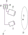
FIG. 1 illustrates a schematic diagram of a system for illumination and imaging, according to one embodiment;
fig. 2 illustrates a schematic diagram of a lighting module according to an embodiment;
fig. 3A and 3B illustrate schematic side and plan views, respectively, of an exemplary lens module in a steerable housing according to one embodiment;
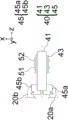
FIG. 4A illustrates a schematic diagram of a linkage for synchronized focusing of an imaging system and steering of an illumination system, according to an embodiment;
FIGS. 4B and 4C illustrate bottom and top views, respectively, of a linkage for synchronized focusing of an imaging system and steering of an illumination system, according to an embodiment;
FIGS. 5A and 5B illustrate bottom views of the linkage at the far and near working distances, respectively, according to one embodiment;
FIGS. 6A and 6B illustrate perspective top and bottom views of an illumination and imaging system according to one embodiment;
FIG. 7 illustrates a housing according to one embodiment;
FIGS. 8A and 8B illustrate perspective views of different exemplary locations in which the system may be used;
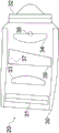
FIG. 9 illustrates a drapery for use with the system according to one embodiment;
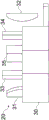
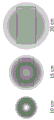
10A-10C illustrate illumination distributions for different illumination configurations;
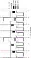
FIG. 11A illustrates a timing diagram for visible and excitation illumination according to one embodiment;
FIG. 11B illustrates a timing diagram for visible and excitation illumination according to one embodiment;
FIG. 11C illustrates a timing diagram for visible and excitation illumination according to one embodiment;
FIG. 11D illustrates a timing diagram for visible and excitation illumination according to one embodiment;
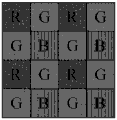
12A-12C illustrate a pixel layout and interpolation scheme according to one embodiment;
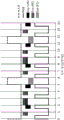
13A-13C illustrate graphs of one embodiment of display method output when a target reticle is placed over regions of non-normalized fluorescence intensity, high relative normalized fluorescence intensity, and medium relative normalized fluorescence intensity, respectively;
FIG. 13D illustrates a graph of one embodiment of a display method output including a time history of signal plots of normalized fluorescence intensity values on a display;
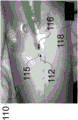
FIG. 14 illustrates a recorded image of an anatomic fluorescence imaging phantom characterized by one embodiment of a display method output displaying normalized fluorescence intensity;
FIG. 15 illustrates an exemplary light source for an exemplary illumination source of the system for illumination shown in FIG. 1; and
FIG. 16 illustrates an exemplary imaging module of the fluorescence imaging system of FIG. 1, including a camera module.
Detailed Description
Example embodiments will now be described more fully hereinafter with reference to the accompanying drawings; however, they may be embodied in different forms and should not be construed as limiting the embodiments set forth herein. Rather, these embodiments are provided so that this disclosure will be thorough and complete, and will fully convey exemplary implementations to those skilled in the art. Various devices, systems, methods, processors, kits, and imaging agents are described herein. While at least two variations of the devices, systems, methods, processors, kits, and imaging agents are described, other variations may include aspects of the devices, systems, methods, processors, kits, and imaging agents described herein combined in any suitable manner with combinations of all or some of the described aspects.
In general, corresponding or analogous reference numbers (when possible) will be used throughout the drawings to refer to the same or corresponding parts.
Spatially relative terms, such as "below," "lower," "upper," and the like, used herein to describe one element or feature's relationship to another element(s) or feature(s) as illustrated in the figures may be used for ease of description. It will be understood that the spatially relative terms are intended to encompass different orientations of the device in use or operation in addition to the orientation depicted in the figures. For example, if the device in the figures is turned over, elements described as "below" or "beneath" other elements or features would then be oriented "above" the other elements or features. Thus, the exemplary term "below" can encompass both an orientation of above and below. The device may be otherwise oriented (rotated 90 degrees or at other orientations) and the spatially relative descriptors used herein interpreted accordingly.
FIG. 1 illustrates a schematic diagram of an illumination and imaging system 10 according to one embodiment. As can be seen therein, the system 10 may include an illumination module 11, an imaging module 13, and a video processor/illuminator (VPI) 14. The VPI 14 may include an illumination source 15 to provide illumination to the illumination module 11 and a processor assembly 16 to send control signals and receive data regarding light detected by the imaging module 13 from the target 12 illuminated by the light output by the illumination module 11. The illumination source 15 may output light of different wavelength regions (e.g., white (RGB) light, excitation light) to cause fluorescence in the object 12, etc., depending on the characteristics to be examined and the material of the object 12. Light of different wavelength bands may be output by the illumination source simultaneously or sequentially. The illumination and imaging system 10 may be used, for example, to facilitate a surgical procedure. The target 12 may be a morphologically complex target, such as a biological material including tissue, anatomical structures, other objects having contours and shapes that cause shadows when illuminated, and so forth. The VPI 14 may record, process, display, etc., the resulting image and associated information.
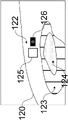
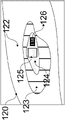
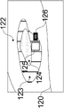
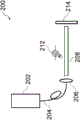
Fig. 2 illustrates a schematic perspective view of the lighting module 11 of fig. 1 according to an embodiment. As can be seen therein, the illumination module 11 may comprise at least two illumination openings directing illumination from an illumination source 23 (which may be comprised in the VPI box 14) to, for example, a rectangular target field 24. Each illumination opening provides illumination on target field 24 such that the light substantially or completely overlaps, for example, at target material 12 (shown in fig. 1). More than two illumination openings may be used. The illumination distributions are substantially similar and substantially overlap at the target 12 to provide uniform illumination of the target 12. The use of the at least two illumination openings reduces shadow effects due to anatomical morphology and helps provide uniform illumination over the target field 24. Directing illumination from the illumination module 11 to the rectangular target field 24 allows matching the area of illumination to the rectangular imaging field of view, which helps provide uniform illumination and enhances the efficiency of the illumination module by reducing extraneous illumination. Matching the illumination field to the imaging field of view also provides a useful indication of the location and extent of the anatomical region currently being imaged.
In some embodiments, light pipes may be used to achieve mixing of the illumination light to produce a uniform illumination profile. The mixing of the illumination light through the light pipe may remove the effect of the structure of the light source on the illumination profile, which may otherwise adversely affect the uniformity of the illumination profile. For example, using a light pipe to mix the illumination light output from a fiber optic light guide may remove an image of the structure of the individual optical fibers from the illumination profile. In some embodiments, a rectangular light pipe may be used to conserve illumination power while matching the illumination profile to the rectangular imaging field of view. In some embodiments, light pipe materials having high refractive indices for both visible and near infrared light (such as optical glass material N-SF 11) may be used for high efficiency illumination power delivery.
According to some embodiments, a rectangular light pipe having an aspect ratio that matches the aspect ratio of the imaging field of view (e.g., both aspect ratios are 16: 9) may be used in conjunction with rotationally symmetric illumination optics.
According to some embodiments, a rectangular light pipe having a different aspect ratio than the imaging field of view (e.g., a square light pipe having an aspect ratio of 16:9 imaging field of view) may be used in conjunction with a cylindrical illumination optic. Cylindrical optical elements may be used to individually follow one or both dimensions of a rectangular illumination profile used to match the aspect ratio of the imaging field of view.
Depending on the desired system requirements and illumination uniformity for the working distance range, various methods for matching the illumination to the rectangular imaging field of view may be used. For example, applications with high requirements on working distance range and illumination uniformity may require the use of illumination optics with dynamic steering in order to adequately match the illumination to the imaging field of view, while applications with lower requirements may be used with fixed illumination optics in order to match the illumination to the field of view.
In some embodiments, one or more illumination optics elements may be rotated by a driver to steer the illumination.
In some embodiments, one or more illumination optics may be translated perpendicular to the imaging optical axis by a driver to steer the illumination.
In some embodiments, one or more illumination optical elements may be configured to provide some distortion in the illumination profile in order to account for distortion inherent to the accompanying imaging system.
In some embodiments, the fixed position and orientation of the illumination optics may be utilized to achieve uniform illumination of the imaging field of view over a specified range of working distances. The offset distance of the illumination optics from the imaging optical axis, along with the orientation of the illumination optics, can be configured to optimize the matching of the illumination profile to the imaging field of view at working distances within a specified range of working distances while also maintaining substantial matching of the illumination profile to the imaging field of view at other working distances within the specified range.
As illustrated in fig. 2, each illumination opening may comprise a lens module 20, a connection cable 22 connected to an illumination light source 23, and a light pipe 21 adapting the high numerical aperture of the connection cable 22 to the lower numerical aperture of the lens module 20. The lens module 20 may be steerable, as described in detail below. In some cases, acceptable performance may be achieved without steering. In other words, only an illumination module providing illumination with a rectangular form factor matching the field of view of the imaging system (e.g. providing uniform illumination within the imaging field of view) using at least two illumination openings (in which each opening produces an illumination gradient such that the illumination flux in the object plane and at each point in the illumination field are reasonably the same) and an imaging device with an illumination module may be sufficient.
Fig. 3A and 3B illustrate side and plan views, respectively, of the lens module 20. The lens module 20 may include a lens mounted in a steerable lens housing 30. As used herein, a lens is any optical element having optical power, whether implemented by a refractive element or a diffractive element. For ease of illustration, other elements not important for understanding, such as a cover enclosing the lens module (see fig. 2), are not shown.
In the particular example shown herein, the lenses may include a pair of horizontal-axis cylindrical lenses 31-32 and a pair of vertical-axis cylindrical lenses 33-34. Also shown is a prism element 35 which can align the illumination light with the intended off-axis. In particular, according to an embodiment, the prism element 35 corrects the angle introduced by the light guide 21 to increase the device compactness. The mounting design for each lens element 31-35 may allow tuning of the magnification and focus of the illumination optics. According to this embodiment, the steerable lens housing 30 encloses and steers three cylindrical lenses 31, 33, 34 and a prism lens element 35 (e.g., collectively referred to as a group). This example of the lens is merely illustrative, and the lens in the lens module 20 may be modified as appropriate.
In this particular embodiment, the base portion of the steerable shell 30 is latched about pivot point 36 to a fixed chassis frame 90 (see fig. 6A) and mechanical linkage 40 (see fig. 4A-4C), described in detail below, respectively, for example using pin 46 (see fig. 6B) inserted into shell aperture 37, while the lens 32 is rigidly connected to the chassis 90, i.e., not to the shell 30 (see fig. 6B).
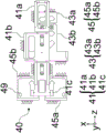
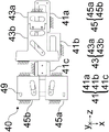
Fig. 4A illustrates a schematic diagram showing the directions of motion provided by the various components of the linkage 40. The linkage 40 may include a drive cam 41, illumination cams 45a, 45b (one for each illumination opening), and an imaging cam 43. The drive cam 41 receives input from a user (see fig. 6) and translates it into synchronous motion of the lens modules 20a, 20B attached to the corresponding illumination cams 45A, 45B via respective housings 30 and pins 46, and the imaging lens 51 and imaging sensor 52 (see fig. 5A and 5B) attached to the imaging cam 43 via a post-pin cam. The imaging lens 51 is shown here as a single field lens, but additional and/or alternative lenses for focusing light from the target 20 onto the imaging sensor 52 may be employed. Each opening has its own associated illumination cam 45A and 45B, shown here as the left and right sides of the input window for receiving light from the target 12.
In particular, translation of the drive cam 41 may translate the imaging cam 43 along the x-axis (which in turn may cause the imaging cam 43 to translate the imaging lens 51 and imaging sensor 52 along the z-axis), as well as the illumination cams 45a, 45b (which in turn simultaneously steer the corresponding lens modules 20a, 20b about the respective pivot points 36), such that steering of the lens modules 20a, 20b is performed synchronously with positional adjustment of the imaging lens 51 and imaging sensor 52 to ensure proper focusing of light from the target on the sensor 52. Alternatively, the imaging cam 43 may merely translate the imaging lens 51 or any other combination of imaging optical elements along the z-axis in order to ensure proper focusing of light from the target on the sensor 52.
Fig. 4B illustrates a bottom view and fig. 4C illustrates a top view of the linkage 40 according to one embodiment. The drive cam 41 may comprise two drive portions 41a and 41b, and a third drive portion 41c (if steering is included), all of which are shown here as being rigidly attached to form a rigid drive cam 41. Similarly, the imaging cam 43 may include two imaging portions 43a and 43 b. The drive cam 41 receives input from the user via the first drive portion 41a (via the control surface 62) and cam-translates the imaging cam 43 via the pins in the drive portion 41b, causing the imaging cam portion 43a to translate the sensor 52 and the imaging cam portion 43b to translate the imaging lens 51. If steering is included in the linkage, the third driving portion 41c simultaneously steers (rotates) the lens modules 20a, 20B using the pins 46 (see fig. 6B) associated with each of the illumination cam portions 45a and 45B by translating the illumination cam portions 45a and 45B. The pin 46 may be inserted through a through slot 49 in each of the illumination cams 45a, 45b and a corresponding housing hole 37 in the lens modules 20a, 20 b. The driving portion 41c simultaneously steers the lens modules 20a, 20b so that both still illuminate the same field of view as each other at the target field of view of the target 12.
Fig. 5A and 5B illustrate bottom views of the linkage in combination with lens modules 20a, 20B, imaging field lens 51 and sensor 52 at the far and near working distances, respectively, according to one embodiment. As can be seen therein, the linkage 40 synchronizes the steering of the illumination source with the focusing of the imaging system at two sample working distance illumination steering settings. Fig. 5A-5B illustrate the positions of lens modules 20a, 20B (rotating about pivot point 37) and lens 51 and sensor 52 (translating along optical axis 55 of the imaging system and along the x-axis) at two focus positions caused by user input.
As illustrated in fig. 5A and 5B, each part moving in axial direction within the linkage 40 may be guided by two fixed rolling elements 47 and one spring-loaded rolling element 48 in order to reduce or minimize friction during movement. The linkage 40 may also include a drive cam input connection point 42.
Fig. 6A and 6B illustrate a perspective top view and a perspective bottom top view of device 10 according to one embodiment. In fig. 6A and 6B, the illumination module 11 and the imaging module 13 are mounted on a chassis 90, with the top portions thereof removed for clarity. Also, a focus actuation mechanism 70 is illustrated that translates motion from user input to motion of the drive cam 41 via the drive cam input connection point 42.
As can be seen in fig. 6A, the optical axis 55 of the imaging module 13 runs through the center of the imaging module, wherein the lens modules 20a, 20b are arranged symmetrically with respect to the imaging optical axis 55. Light to be imaged from the target 12 travels along the optical axis 55 so as to be incident on the lens 51 and the sensor 52. A wavelength dependent aperture 53 comprising a smaller central aperture allowing transmission of all visible and fluorescent light (e.g. Near Infrared (NIR) light) and a surrounding larger aperture blocking transmission of visible light but allowing transmission of fluorescent light may be provided upstream of the lens 51.
Referring to fig. 6B and 4A-4B, pin 46 connects lens module 20 via housing hole 37 in housing 30, slot 49 of linkage 40. Also, a pivot point pin 44 connects the lens module 20 to the chassis 90.
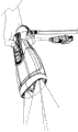
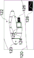
Fig. 7 illustrates one embodiment of an ergonomic housing 60 enclosing the illumination module 11 and the imaging module 13. The ergonomic housing 60 is designed to be held in different modes of use/configurations, such as a pistol grip (fig. 8A) for forward imaging in a scanning imaging orientation and a vertical orientation grip (fig. 8B) for use when imaging downward in an overhead imaging orientation. As can be seen in fig. 7, the housing 60 includes a control surface 62, a gripping detail 64, a window frame 68 and a nose clip 66. The ergonomic housing 60 may be connected to the VPI box 14 via a light guide cable 67 (through which light is provided to the illumination openings 20a, 20 b) and a data cable 65 (which carries power, sensor data) and any other (non-optical) connection.
The control surface 62 includes focus buttons 63a (decreasing working distance) and 63b (increasing working distance) that control the linkage 40. Other buttons on the control surface 62 may be programmable and may be used for various other functions (e.g., excitation laser power on/off, display mode selection, white light imaging white balance, saving screenshots, etc.). As an alternative to or in addition to the focus button, a proximity sensor may be provided on the housing and may be employed to automatically adjust the linkage 40.
As can be seen in fig. 8A, when the housing 60 is held with the imaging window facing forward, the thumb rests on the control surface 62, while the other fingers on the operator's hand wrap loosely around the bottom of the grip detail 64. As can be seen in fig. 8B, when the housing 60 is held with the imaging window facing down, the grip detail 64 is between the thumb and forefinger and the fingers wrapped around to access the control buttons or activate the control surface 62. The grip detail 64 is shaped to provide partial support for the weight of the device held in a vertical orientation on top of the wrist so that the housing 60 can hang loosely and does not require a tight grip of the housing 60. Thus, the housing 60 can be manipulated by a single hand in multiple orientations. In various other embodiments, the housing 60 may be supported on a support (e.g., a movable support).
The window frame 68 (see also fig. 9) defines various windows for the housing 60. In other words, the window frame 68 defines windows 68a and 68b corresponding to the two lens modules 20a and 20b, and a window 68c (which serves as an input window for light from a target to be incident on the sensor 52).
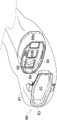
As illustrated in fig. 9, the housing 60 may be used in conjunction with a drapery 80. The drape 80 may be a surgical drape suitable for use during a surgical procedure. The drapery includes drapery material 81, a drapery lens 82, a drapery window frame 83 around the drapery lens, and an interlock interface 84 integrated with the drapery window frame 83. The drape material 81 is used to enclose the device in the housing 60 and cover anything else as desired. The drapery window frame 83 may follow the shape of the housing nose clip 66 so that the drapery window frame 83 may be inserted therein without obstructing the windows 68 a-68 c. The drapery 80 is designed to minimize reflection and imaging ghosts by ensuring that the drapery lens 82 is flush with the imaging and illumination window frame 68, for example, within 0.5 millimeters. The drape 80 may use an interlocking interface 84, which interlocking interface 84 may fit into a recess on the inner surface of the housing nose clip 66 to be secured flush therewith.
One or more interlock interfaces 84 may be used on the inner or outer surface of the housing nose clip 66 to ensure a safe and tight fit of the drapery lens 82 against the window frame 68. In the particular embodiment shown, two interfaces 84 for engagement by the inner surface of the housing nose clip 66 are used (here one on top of the drapery window frame 83 and one on the bottom of the drapery window frame 83).
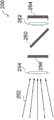
Fig. 10A-10C illustrate typical illumination distributions (fills) with respect to a rectangular imaging field of view (profile) at working distances of 10cm (left column), 15cm (middle column), and 20cm (right column) for an illumination ring (fig. 10A), a pair of fixed anamorphic projection illumination sources (fig. 10B), and a pair of steered anamorphic projection illumination sources (fig. 10C) according to one embodiment. Fig. 10A illustrates the use of illuminated split rings to minimize shadows but not match the illumination to the imaging field of view and may not provide uniform illumination (e.g., distribution as a function of distance) at all working distances. Fig. 10B illustrates anamorphic projections from two illumination sources that are fixed (using, for example, an illumination lens arrangement featuring a cylindrical lens or an engineered diffuser), so they are well collimated to achieve uniform illumination that matches the imaging field of view at a fixed working distance (e.g., 15 centimeters), but they are not as uniform or well matched at other distances (whether smaller or larger). As noted above, such lighting is often acceptable by itself. Fig. 10C illustrates the ability to better maintain uniform illumination and constrain the illumination to the field of view by diverting the illumination when changing the working distance (and imaging focus), according to one embodiment.
As noted above, the illumination used may include both white light and fluorescence excitation illumination, e.g., from a laser, to excite Near Infrared (NIR) light from the target. However, ambient light may interact with light from the target.
Fig. 11A illustrates timing diagrams for white light (RGB) and fluorescence excitation (laser) illumination, and visible light (VIS) and NIR Fluorescence (FL) imaging sensor exposures configured to allow ambient room light to be subtracted from the fluorescence signal with a single sensor. As used herein, a white pulse will indicate that white light (RGB) is illuminating the target and an excitation pulse will indicate that laser light is illuminating the target.
Exposures of even (Exp 1) and odd (Exp 2) sensor pixel rows are shown interleaved with different exposure times to facilitate estimated isolation of ambient room light signal components. Such an interleaved exposure readout mode is provided on some imaging sensors, such as the 'high dynamic range interleaved readout' mode on the cmos CMV2000 sensor.
Pulsing the white light illumination at 80Hz brings the frequency of the strobe light above what the human eye can perceive, or this may trigger a seizure. The visible image exposure may be longer (e.g., twice) than the RGB illumination to ensure overlap between the exposure frame rate at 60H and the 80Hz RGB illumination pulses. Due to the much greater intensity of the RGB illumination pulses and signals from the target 12, additional ambient light captured during the visible light exposure may be ignored.
By setting the NIR fluorescence image exposure time, Exp1 and Exp2 acquire the field and quarter frame periods, respectively, while running the excitation laser only in the last quarter of every three frames, the even line (Exp 1) records the field of ambient room light in addition to the quarter frame of NIR fluorescence, while the odd line (Exp 2) records the quarter frame of ambient room light plus the quarter frame of NIR fluorescence. Performing these fractional exposures within each visible or NIR fluorescent frame minimizes motion artifacts that would otherwise be caused by inserting additional exposure frames in the frame sequence for the purpose of ambient room light subtraction.
With such an acquisition design, an estimate of the ambient room light contribution to the image signal can be isolated by subtracting the Exp2 sensor line of the NIR fluorescence image from the Exp1 sensor line (interpolated to match the Exp2 pixel locations), yielding an estimate of the quarter frame of the ambient room light signal. The estimate of the quarter frame of the ambient room light signal may then be subtracted from the Exp2 sensor row of the NIR fluorescence image to produce an estimate of the NIR fluorescence signal with the quarter frame of ambient room light removed. Control of the illumination and exposure may be performed by the VPI box 14.
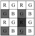
In one embodiment, the above chamber light subtraction method may be varied to accommodate the use of a bayer pattern color sensor. Fig. 12A illustrates a bayer pattern arrangement of color sensor pixels, where even and odd sensor rows have different filter arrangements (e.g., no red pixels in the even sensor rows and no blue pixels in the odd sensor rows), so ambient light recorded on the even rows will not be able to estimate well where it reaches the odd rows in the same period. However, each row does include a green pixel signal that is also sensitive to NIR fluorescence. Using only green pixels and performing two-dimensional interpolation from green pixel signals to other pixel locations may yield estimates of ambient light signal components and thus also NIR fluorescence or visible light components for NIR and visible light images, respectively.
To calculate the NIR signal value at a given location, Exp1 (even lines) and Exp2 (odd lines) green pixel values near that location are calculated, where one or both of these values need to be interpolated. Fig. 12B shows an example in which the best estimate of Exp1 (even rows) green values at red pixel locations is the average of the immediately above and below green values, while the best estimate of Exp2 (odd rows) green values is the average of the immediately left and right green values.
The following mathematical example is used to illustrate one embodiment of the ambient room light subtraction method. If a = ambient light incident in a quarter frame period and F = fluorescence incident in a quarter frame period, then:
solving for F yields:
F = 2*Exp 2 – Exp 1。
in the particular example illustrated in fig. 11A, the period for sensing is three frames, the white light pulse and the excitation pulse have the same duration or width but different frequencies, visible light is sensed during two frames (e.g., the first two frames) and fluorescence is sensed during one frame (e.g., the third or last frame) for two different exposure times. As shown therein, the visible light exposure time may be twice the duration of the white light pulse, the first fluorescence exposure time may be equal to the duration of the excitation pulse, and the second fluorescence exposure time may be a longer (e.g., twice) pulse than the excitation pulse. Further, the visible light exposure may have a different frequency than the white light pulses, e.g., the visible light exposure does not occur with each white light pulse, while the fluorescence exposure may have the same frequency as the excitation pulses.
Alternative timing and exposure maps are discussed below in which a sensor having rows that are all active for a common exposure duration may be used while a single sensor is used to compensate for ambient light. For example, the background light may be detected directly by the sensor when the target is not illuminated. Other variations on pulsing, exposing, and sensing may be apparent to those skilled in the art.
Fig. 11B illustrates an alternative timing diagram for white light (RGB) and fluorescence excitation (laser) illumination, and visible light (VIS) and NIR Fluorescence (FL) imaging sensor exposures configured to allow subtraction from ambient room light of a fluorescence signal with a single sensor. The exposures to visible light and to fluorescence are shown in sequence along with the exposure used to capture the Background (BG) image signal due to ambient light. The white light illumination may be pulsed at 80Hz as described above. The fluorescence excitation illumination may be pulsed at 20Hz and the pulse duration or width may be increased (e.g., up to twice the white light pulse duration) to achieve a longer corresponding fluorescence exposure. If an imaging sensor with a global shutter is used, each sensor exposure must terminate at the end of the imaging frame with a readout period. The exposure to capture the ambient light background image signal may be performed at the end portion of the frame in the absence of any pulsed white light or excitation light. As shown in the example in fig. 11B, where video is acquired at a frame rate of 60Hz, a white light illumination pulse width of quarter frame duration may be used when the end of the white light illumination pulse is aligned with the end of a frame, along with the quarter frame duration visible light exposure that occurs in each frame.
The scaled image signals recorded during one or more background exposures may be subtracted from each fluorescence exposure image to remove the contribution of ambient light from the fluorescence image. For example, the image signal from a quarter frame duration background exposure may be scaled up by a factor of two and subtracted from the subsequent image signal from a half frame duration fluorescence exposure. As another example, both a quarter frame duration background exposure image signal before a half frame duration fluorescence exposure image signal, and a second quarter frame background image signal after fluorescence exposure may be subtracted from the fluorescence image signal. The scaling of the image signal from the first and second background exposures may comprise interpolation of pixel values from the first exposure time point and the second exposure time point in order to estimate a pixel value corresponding to the intermediate time point.
The use of an imaging sensor with a high speed readout that enables higher video frame acquisition rates may allow additional exposure periods to be allocated within the illumination and exposure timing scheme for a given white light pulse frequency. For example, maintaining 80Hz white light illumination pulses as above and using a sensor with a higher video frame acquisition rate (such as 120 Hz) may allow additional white light, ambient background, or fluorescence to be exposed for a given period of time, as compared to when using a slower video frame acquisition rate (such as 60 Hz).
In the particular example illustrated in fig. 11B, the period for sensing is three frames, the excitation pulse has twice the width of the white light pulse, visible light is sensed during one frame (e.g., the first frame), background light is sensed during one frame (e.g., the second frame), and fluorescence is sensed during one frame (e.g., the third or last frame). Here, the visible light exposure time may be equal to the duration of the white light pulse, the background exposure time may be equal to the duration of the white light pulse, and the fluorescence exposure time may be equal to the duration of the excitation pulse. Further, the visible light exposure may have a different frequency than the white light pulses, e.g., the visible light exposure does not occur with each white light pulse, while the fluorescence exposure may have the same frequency as the excitation pulses. Finally, the background exposure may occur only once within the period.
Fig. 11C illustrates an alternative timing diagram for white light (RGB) and fluorescence excitation (laser) illumination, and visible light (VIS) and NIR Fluorescence (FL) imaging sensor exposures configured to allow ambient room light subtraction from a fluorescence signal with a single sensor at a 120Hz video frame acquisition rate. A white light pulse frequency of 80Hz is used and when the end of the white light illumination pulse aligns with the end of the frame, a half-frame duration white light illumination pulse width may be used, along with the half-frame duration visible light exposure that occurs in each frame. The fluorescence excitation illumination is shown pulsed at 40Hz in case of pulse duration of one frame to achieve a higher frequency corresponding to the fluorescence exposure. The exposure to capture the ambient light background image signal may be performed at the end portion of the frame in the absence of any pulsed white light or excitation light, such as the exposure of half-frame duration that occurs in the frame between a fluorescence exposure and a subsequent white light exposure, as shown in this example embodiment.
In the particular example illustrated in fig. 11C, the period for sensing is three frames, the width of the excitation pulse is twice the width of the white light pulse, visible light is sensed during one frame (e.g., the second frame), background light is sensed during one frame (e.g., the first frame), and fluorescence is sensed during one frame (e.g., the third or last frame). Here, the visible light exposure time may be equal to the duration of the white light pulse, the background exposure time may be equal to the duration of the white light pulse, and the fluorescence exposure time may be equal to the duration of the excitation pulse. Further, the visible light exposure may have a different frequency than the white light pulses, e.g., the visible light exposure does not occur with each white light pulse, while the fluorescence exposure may have the same frequency as the excitation pulses. Finally, the background exposure may occur only once within the period.
Depending on the intensity of the fluorescence excitation light used, there may be safety considerations limiting the duration and frequency of the excitation light pulses. One method for reducing the intensity of the applied excitation light is to reduce the duration of the excitation light pulse and the corresponding fluorescence exposure. Additionally or alternatively, the frequency of the excitation light pulses (and the corresponding fluorescence exposures) may be reduced, and instead the readout period that would otherwise be available for fluorescence exposures may be used for background exposures to improve the measurement of ambient light.
Fig. 11D illustrates an alternative timing diagram for white light (RGB) and fluorescence excitation (laser) illumination, and visible light (VIS) and NIR Fluorescence (FL) imaging sensor exposures configured to allow ambient room light subtraction from a fluorescence signal with a single sensor at a 120Hz video frame acquisition rate. A white light pulse frequency of 80Hz is used and when the end of the white light illumination pulse aligns with the end of the frame, a half-frame duration white light illumination pulse width may be used, along with the half-frame duration visible light exposure that occurs in each frame. The fluorescence excitation illumination pulsed at 20Hz is shown in the case of a pulse duration of one frame. The exposure to capture the ambient light background image signal may be performed at the end portion of the frame in the absence of any pulsed white light or excitation light, such as a background exposure of half-frame duration occurring in the frame between the fluorescence exposure and the successive first white light exposure, and both a first background exposure and a second background exposure of half-frame duration occurring in the frame between the first white light exposure and the successive second white light exposure, as shown in this example embodiment.
In the particular example illustrated in fig. 11D, the period for sensing is six frames, the excitation pulse has twice the width of the white light pulse, the visible light is sensed during two frames (e.g., the second and fifth frames), the background light is sensed during three frames (e.g., the first, third, and fourth frames), and the fluorescence is sensed during one frame (e.g., the sixth or last frame). Here, the visible light exposure time may be equal to the duration of the white light pulse, the background exposure time may be equal to the duration of the white light pulse or twice thereof, and the fluorescence exposure time may be equal to the duration of the excitation pulse. Further, the visible light exposure may have a different frequency than the white light pulses, e.g., the visible light exposure does not occur with each white light pulse (e.g., only occurs twice within the time period), while the fluorescent light exposure may have the same frequency as the excitation pulses. Finally, the background exposure may occur three times over a period of total duration equal to four times the duration of the white light pulse.
To improve the performance of such ambient room light compensation methods as described above, a wavelength dependent aperture (e.g., element 55 in fig. 6A) may be used that includes a smaller central aperture that allows transmission of all visible and NIR light and a surrounding larger aperture that blocks visible light but allows transmission of NIR light. The use of such a wavelength dependent aperture allows a larger proportion of NIR signal to be collected relative to visible light signal, which improves the performance of image signal subtraction for estimating and removing ambient room light components. The wavelength dependent aperture may also be characterized by a third larger aperture around the other smaller apertures, which blocks both visible and NIR light. As one example, the wavelength dependent apertures may include membrane apertures in which a film of material (e.g., a plastic or glass film) that blocks transmission of visible light but allows transmission of NIR light has a central opening (e.g., a hole) that allows transmission of both visible and NIR light. Such a membrane aperture may comprise a material that prevents transmission of visible light by reflection and/or a material that prevents transmission of visible light by absorption. As another example, the wavelength dependent apertures may include dichroic apertures formed by mask film deposition on a single substrate, with a film that allows transmission of visible and NIR light deposited on the smaller central aperture, and a second film that blocks transmission of visible light but allows transmission of NIR light deposited on the surrounding larger aperture. The corresponding aperture sizes of the smaller central aperture of the wavelength dependent aperture and the surrounding larger aperture may be set so as to make the depth of field appear substantially similar for visible light and for NIR light when imaged by the imaging system. One or more wavelength dependent filters may be placed in different locations throughout the device, in which case the rejection of visible light and the passage of NIR signals may be optimized. For example, such a wavelength dependent filter may be positioned just in front of the lens 51. As another example, one or more wavelength dependent filters may be placed in the pupil plane of the imaging lens.
This may be useful, for example, to facilitate comparison of fluorescence signals of different regions, to display a target reticle around a region within an imaging field of view, and to calculate and display normalized fluorescence intensity within the region. Normalization of the measured fluorescence intensity values may allow meaningful comparison of multiple images and corresponding values. To correct for variations in measured fluorescence intensity with working distance (e.g., the distance of the imaging system to the imaged anatomy), the normalized fluorescence intensity value can be based on the ratio between the measured fluorescence intensity value and the light value reflected within the target reticle area.
A numerical representation of the normalized fluorescence intensity values within the target reticle field may be displayed on or near the image frame to facilitate comparing values when targeting the target reticle at different locations on the imaged anatomy. For example, the numerical representation may be an average of the normalized fluorescence intensity values for all image pixels in the target reticle area.
Additionally or alternatively, a time history map of the numerical representation of normalized fluorescence intensity values within the target reticle field may be displayed on or near the image frame to facilitate comparing values when targeting a target reticle at different locations on the imaged anatomy or at the same location over a series of time points. Such a temporal history map may further assist the user in assessing the fluorescence profile in the imaged tissue surface by scanning across the anatomical region of interest and viewing the relative normalized fluorescence intensity profile map.
FIG. 13A illustrates a diagram of sample display output from one embodiment of a display method in which a target reticle 125 is positioned within an area of the imaged anatomy 120 that is free of fluorescence intensity 122 and a numerical representation of fluorescence intensity 126 is displayed near the target reticle 125. FIG. 13B illustrates a plot of another sample display output in which the target reticle 125 is positioned over an area of high relative normalized fluorescence intensity 124 and a corresponding numerical representation 126 of the relatively high fluorescence intensity is shown. FIG. 13C illustrates a plot of another sample display output in which the target reticle 125 is positioned over an area of medium relative normalized fluorescence intensity 124 and a corresponding numerical representation 126 of the relative medium fluorescence intensity is shown. FIG. 13D illustrates a plot of sample display output in which the target reticle 125 is positioned over an area of medium relative normalized fluorescence intensity 124 and shows a time history plot 128 of a numerical representation of normalized fluorescence intensity consistent with sequential imaging of areas of zero, high, and medium relative normalized fluorescence intensity. Alternatively or additionally, to display the numerical representation and/or the historical map on the target, a display area associated with the target reticle (e.g., on the device itself or some other display) may display this information.
Figure 14 illustrates a recorded image of an anatomic fluorescence imaging phantom featuring one embodiment of a display method output displaying normalized fluorescence intensity. In particular, the target 110 is illuminated with excitation light and a target reticle 115 is placed over the region of fluorescence intensity 112 according to one embodiment. The numerical representation of the target reticle 115 is displayed in a field 116 associated with the target reticle 115. A time history plot 118 of numerical representations of normalized fluorescence intensity attributed to imaging of different locations of the reticle 115 can be displayed.
Such a display method may be useful for a variety of fluorescence imaging systems, including endoscopic or laparoscopic fluorescence imaging systems, open field fluorescence imaging systems, or combinations thereof. Such normalization and display of fluorescence intensity values may allow for useful quantitative comparison of relative fluorescence intensity between image data from various time points within an imaging session. Such normalization and display of fluorescence intensity values may further allow for useful quantitative comparisons of relative fluorescence intensity between image data from different imaging sessions, by combination with appropriate standardized fluorescence agent management and imaging protocols, and standardized calibration of the imaging device.
Examples are given.
Fluoroscopic medical imaging system for acquisition of image data。
In some embodiments, the system for illumination and imaging of a patient may be used with or as a component of a medical imaging system, such as, for example, a fluorescence medical imaging system for acquiring fluorescence medical image data. One example of such a fluorescence medical imaging system is a fluorescence imaging system 10 schematically illustrated in fig. 1. In this embodiment, the fluorescence imaging system 10 is configured to acquire a time series of fluorescence signal intensity data (e.g., images, video) that captures the transport of the fluorescence imaging agent through the tissue.
The fluorescence imaging system 10 (FIG. 1) includes: an illumination source 15 and an illumination module 11 for illuminating tissue of a patient so as to induce fluorescence emissions from a fluorescence imaging agent 17 in the tissue of the patient (e.g., in blood); an imaging module 13 configured to acquire a time series of fluorescence images from the fluorescence emissions; and a processor component 16 configured to utilize a time series of fluorescence images (fluorescence signal intensity data) acquired according to various embodiments described herein.
In various embodiments, the illumination source 15 (FIG. 1) includes, for example, a light source 200 (FIG. 15) comprising a fluorescence excitation source configured to generate excitation light having an appropriate intensity and an appropriate wavelength for exciting the fluorescent imaging agent 17. Light source 200 in fig. 15 includes a laser diode 202 (which may include, for example, one or more fiber coupled laser diodes) configured to provide excitation light for exciting fluorescent imaging agent 17 (not shown). Examples of other sources of excitation light that may be used in various embodiments include one or more LEDs, arc lamps, or other illumination techniques of sufficient intensity and appropriate wavelength to excite fluorescent imaging agents 17 in tissue (e.g., in blood). For example, excitation of the fluorescent imaging agent 17 in blood may be performed using one or more 793nm conduction-cooled single-rod fiber-coupled Laser Diode modules from DILAS Diode Laser, ltd, germany, where the fluorescent imaging agent 17 is a fluorescent dye with near-infrared excitation characteristics.
In various embodiments, the light output from the light source 200 in fig. 15 may be projected through an optical element (e.g., one or more optical elements) to shape and direct the output used to illuminate the tissue region of interest. The shaping optics may consist of one or more lenses, light guides and/or diffractive elements in order to ensure a flat field over substantially the entire field of view of the imaging module 13. In particular embodiments, the fluorescence excitation source is selected to emit at a wavelength near the absorption maximum of the fluorescence imaging agent 17 (e.g., ICG). For example, referring to the embodiment of light source 200 in fig. 15, the output 204 from laser diode 202 passes through one or more focusing lenses 206 and then through a homogeneous light pipe 208 (such as, for example, a light pipe commonly available from Newport corporation, usa). Finally, the light is passed through an optical diffractive element 214 (e.g., one or more optical diffusers), such as, for example, a ground glass diffractive element also available from Newport corporation, usa. The laser diode 202 itself is powered by, for example, a high current laser driver such as those available from luminea Power limited, usa. The laser may optionally be operated in a pulsed mode during the image acquisition process. In this embodiment, an optical sensor, such as a solid state photodiode 212, is incorporated in the light source 200 and samples the illumination intensity produced by the light source 200 via reflections scattered or diffuse reflections from various optical elements. In various embodiments, additional illumination sources may be used to provide guidance when aligning and positioning the modules within the region of interest. In various embodiments, at least one of the components of the light source 200 depicted in fig. 15 may be a component that includes the illumination source 15 and/or includes the illumination module 11.
Referring back to FIG. 1, in various embodiments, imaging module 13 may be, for example, a component of fluorescence imaging system 10 configured to acquire a time series (e.g., video) of fluorescence images from fluorescence emissions from fluorescence imaging agent 17. Referring to fig. 16, one exemplary embodiment of imaging module 13 is shown including camera module 250. As shown in fig. 16, the camera module 250 acquires an image of the fluorescence emissions 252 from a fluorescence imaging agent 17 in tissue (not shown), such as blood, by using a system of imaging optics (e.g., a front element 254, a rejection filter 256, a dichroic element 260, and a back element 262) to collect and focus the fluorescence emissions on an image sensor assembly 264 that includes at least one 2D solid-state image sensor. Rejection filter 256 may be, for example, a notch filter to reject one wavelength band corresponding to excitation light. The dichroic element 260 may be, for example, a dichroic mirror to selectively pass a subset of the incoming light wavelength spectrum and redirect the remaining wavelengths out of the optical path for rejection or toward a separate image sensor. The solid-state image sensor may be a Charge Coupled Device (CCD), CMOS sensor, CID, or similar 2D sensor technology. The charge resulting from the optical signal transduced by the image sensor assembly 264 is converted to an electrical video signal (which includes both digital and analog video signals) by appropriate readout and amplification electronics in the camera module 250.
According to some embodiments, an excitation wavelength of about 800nm +/-10 nm and an emission wavelength > 820nm is used along with NIR compatible optics for ICG fluorescence imaging. One skilled in the art will appreciate that other excitation and emission wavelengths may be used for other imaging agents.
Referring back to fig. 1, in various embodiments, the processor assembly 16 includes, for example,
a processor module (not shown) configured to perform various processing operations, including executing instructions stored on a computer-readable medium, wherein the instructions cause one or more of the systems described herein to perform the methods and techniques described herein, and
a data storage module (not shown) to record and store data from the operations and, in some embodiments, to store instructions executable by the processor module to perform the methods and techniques disclosed herein.
In various embodiments, the processor module comprises any computer or computing device, such as, for example, a tablet, laptop, desktop, networked computer, or dedicated stand-alone microprocessor. Inputs are obtained, for example, from the image sensor 264 of the camera module 250 shown in fig. 16, from solid state photodiodes in the light source 200 in fig. 15, and from any external control hardware, such as foot switches or remote controls. The output is provided to a laser diode driver, and an optical alignment aid. In various embodiments, the processor component 16 (fig. 1) may have a data storage module with the capability to save a time series of input data (e.g., image data) to a tangible, non-transitory computer readable medium, such as, for example, an internal memory (e.g., a hard disk or flash memory) in order to enable the recording and processing of the data. In various embodiments, the processor module may have an internal clock to ensure control of the various elements and to ensure proper timing of the illumination and sensor shutters. In various other embodiments, the processor module may also provide graphical displays of user inputs and outputs. The fluoroscopic imaging system may optionally be configured with a video display (not shown) to display images being acquired or played back after recording, or to further visualize data as generated at various stages of the above-described method.
In operation and with continued reference to the exemplary embodiment in fig. 1, 15 and 16, the patient is in position for imaging, in which case the anatomical region of interest of the patient is located beneath both the illumination module 11 and the imaging module 13, such that a substantially uniform illumination field is produced across substantially the entire region of interest. In various embodiments, prior to administering the fluorescent imaging agent 17 to the patient, an image of the region of interest may be acquired for background subtraction purposes. To do so, for example, an operator of the fluoroscopic imaging system 10 in fig. 1 may initiate a time sequence of fluoroscopic images (e.g., video) by depressing a remote switch or foot control or via a keyboard (not shown) connected to the processor assembly 16. Accordingly, the illumination source 15 is turned on and the processor assembly 16 begins recording the fluorescence image data provided by the image acquisition assembly 13. Instead of the pulse patterns discussed above, it will be appreciated that in some embodiments, the illumination source 15 may include a transmission source that continues to be turned on during the image acquisition sequence. When operating in the pulsed mode of the embodiment, the image sensor 264 in the camera module 250 (fig. 16) is synchronized to collect the fluorescent emissions following the laser pulses generated by the diode laser 202 in the light source 200 (fig. 15). In this way, the maximum fluorescence emission intensity is recorded and the signal-to-noise ratio is optimized. In this embodiment, the fluorescence imaging agent 17 is administered to the patient and the fluorescence imaging agent 17 is delivered to the region of interest via arterial flow. For example, the acquisition of the time series of fluorescence images is initiated shortly after administration of the fluorescence imaging agent 17, and the time series of fluorescence images throughout the entrance of the fluorescence imaging agent 17 is acquired from substantially the entire region of interest. The fluorescent light emitted from the region of interest is collected by the collection optics of camera module 250. The residual ambient and reflected excitation light is attenuated by subsequent optics in camera module 250 (e.g., optics 256 in fig. 16, which may be a filter) so that the fluorescent emissions can be acquired by image sensor assembly 264 with minimal light interference from other sources.
In various embodiments, the processor is in communication with or a component of the imaging system. Program code or other computer readable instructions according to various embodiments may be written and/or stored in any suitable programming language and delivered to a processor in various forms including, for example, but not limited to, information permanently stored on a non-writable storage medium (e.g., read-only memory device such as a ROM or CD-ROM disk), information alterably stored on a writable storage medium (e.g., hard disk drive), information conveyed to the processor via a transitory medium such as a signal, information conveyed to the processor via a communication medium such as a local area network, a public network such as the internet, or any type of medium suitable for storing electronic instructions. In various embodiments, the tangible, non-transitory computer-readable medium includes all computer-readable media. In some embodiments, only computer readable instructions for performing one or more of the methods or techniques discussed herein may be stored on the non-transitory computer readable medium.
In some embodiments, the illumination and imaging system may be a component of a medical imaging system that acquires medical image data, such as the fluoroscopic medical imaging system 10. In embodiments where the illumination and imaging system is a component of an imaging system, such as the fluoroscopic imaging system described above, the light source, illumination module, imaging module and processor of the medical imaging system may function as the camera assembly and processor of the illumination and imaging system. Those skilled in the art will recognize that imaging systems other than fluorescence imaging systems may be employed for use with illumination and/or imaging systems such as those described herein (depending on the type of imaging being performed).
Exemplary imaging Agents for use in generating image data。
According to some embodiments, in a fluorescence medical imaging application, the imaging agent is a fluorescence imaging agent (such as, for example, an indocyanine green (ICG) dye). When ICG is administered to a patient, it binds to blood proteins and circulates with the blood in the tissues. A fluorescent imaging agent (e.g., ICG) may be administered to a patient as a bolus injection (e.g., into a vein or artery) at a concentration suitable for imaging, such that the bolus circulates in the vasculature and through the microvasculature. In other embodiments where multiple fluorescent imaging agents are used, such agents may be administered simultaneously, for example in a single bolus, or sequentially in separate boluses. In some embodiments, the fluorescent imaging agent may be administered through a catheter. In certain embodiments, the fluorescent imaging agent may be administered less than one hour before performing the measurement of the intensity of the signal caused by the fluorescent imaging agent. For example, the patient may be administered a fluorescent imaging agent for less than 30 minutes prior to the measurement. In still other embodiments, the fluorescent imaging agent may be administered for at least 30 seconds before the measurement is performed. In still other embodiments, the fluorescent imaging agent may be administered simultaneously with the measurement being performed.
According to some embodiments, the fluorescent imaging agent may be administered at various concentrations to achieve a desired circulating concentration in the blood. For example, in embodiments where the fluorescence imaging agent is ICG, the fluorescence imaging agent may be administered at a concentration of about 2.5 mg/mL in order to achieve a circulating concentration in the blood of about 5 μ Μ to about 10 μ Μ. In various embodiments, the upper concentration limit for administration of the fluorescent imaging agent is the concentration at which the fluorescent imaging agent becomes clinically toxic in circulating blood, and the lower concentration limit is an instrument limit for acquiring signal intensity data caused by the fluorescent imaging agent as the blood circulates in order to detect the fluorescent imaging agent. In various other embodiments, the upper concentration limit for administration of the fluorescent imaging agent is the concentration at which the fluorescent imaging agent becomes self-quenching. For example, the circulating concentration of ICG may range from about 2 μ Μ to about 10 mM. Thus, in one aspect, the method includes the steps of administration of an imaging agent (e.g., a fluorescent imaging agent) to the patient and acquisition of signal intensity data (e.g., video) prior to processing the signal intensity data in accordance with various embodiments. In another aspect, the method excludes any step of administering an imaging agent to the patient.
According to some embodiments, a suitable fluorescence imaging agent for use in a fluorescence imaging application used to generate fluorescence image data is an imaging agent that can circulate with blood (e.g., a fluorescent dye that can circulate with, for example, components of blood, such as lipoproteins or serum plasma in blood) and carry vasculature of tissue (i.e., large blood vessels and microvasculature) and produce signal intensity therefrom when exposed to suitable light energy (e.g., excitation light energy or absorption light energy). In various embodiments, the fluorescence imaging agent comprises a fluorescent dye, an analog thereof, a derivative thereof, or a combination of these. Fluorescent dyes include any non-toxic fluorescent dye. In certain embodiments, the fluorescent dye optimally fluoresces in the near infrared spectrum. In certain embodiments, the fluorescent dye is or includes a tricarbocyanine dye. In certain embodiments, the fluorescent dye is or includes indocyanine green (ICG), methylene blue, or a combination thereof. In other embodiments, the fluorescent dye is or includes fluorescein isothiocyanate, rhodamine, phycoerythrin, phycocyanin, allophycocyanin, o-phthaldehyde, fluorescamine, rose bengal, trypan blue, fluorogold, or a combination thereof that can be excited using an excitation light wavelength suitable for each dye. In some embodiments, analogs or derivatives of fluorescent dyes may be used. For example, a fluorescent dye analog or derivative includes a fluorescent dye that has been chemically modified but still retains its ability to produce fluorescence when exposed to light energy of an appropriate wavelength.
In various embodiments, the fluorescence imaging agent can be provided as a lyophilized powder, solid, or liquid. In certain embodiments, the fluorescence imaging agent may be provided in a vial (e.g., a sterile bottle) that may allow reconstitution to the appropriate concentration by administering a sterile fluid with a sterile syringe. Reconstitution can be performed using any suitable carrier or diluent. For example, a fluorescence imaging agent can be reconstituted with an aqueous diluent immediately prior to administration. In various embodiments, any diluent or carrier that holds the fluorescent imaging agent in solution may be used. As one example, ICG may be reconstructed using water. In some embodiments, once the fluorescence imaging agent is reconstituted, it may be mixed with additional diluents and carriers. In some embodiments, the fluorescent imaging agent may be conjugated to another molecule (such as a protein, peptide, amino acid, synthetic polymer, or sugar), for example, to enhance solubility, stability, imaging properties, or a combination thereof. Additional buffers may optionally be added, including Tris, HC1, NaOH, phosphate buffer, and/or HEPES.
One skilled in the art will recognize that while a fluorescent imaging agent is described in detail above, other imaging agents may be used depending on the optical imaging modality in conjunction with the systems, methods, and techniques described herein.
In some embodiments, the fluorescence imaging agents used in conjunction with the methods and systems described herein may be used for blood flow imaging, tissue perfusion imaging, lymph imaging, or combinations thereof, which may be performed during invasive surgical procedures, minimally invasive surgical procedures, non-invasive surgical procedures, or combinations thereof. Examples of invasive surgical procedures that may involve blood flow and tissue perfusion include cardiac-related surgical procedures (e.g., CABG in extracorporeal or non-extracorporeal circulation) or reconstructive surgical procedures. Examples of such non-invasive or minimally invasive procedures include wound (e.g., chronic wounds such as, for example, pressure sores) treatment and/or management. Examples of lymph imaging include identification of one or more lymph nodes, lymph node drainage, lymph visualization, or a combination thereof. In some variations, such lymph imaging may be related to the female reproductive system (e.g., uterus, cervix, vulva). In some embodiments, the fluorescence imaging agent may be administered in sufficient concentration and in an appropriate manner to achieve lymphatic imaging.
Tissue perfusion involves the microcirculation flow of blood per unit volume of tissue, where oxygen and nutrients are provided to, and waste products are removed from, the capillary beds of the tissue being perfused. Tissue perfusion is a phenomenon related to, but distinct from, blood flow in a blood vessel. Quantitative blood flow through a blood vessel can be expressed in terms of a defined flow (i.e., volume/time) or a defined velocity (i.e., distance/time). Tissue blood perfusion defines the movement of blood through microvasculature (such as arterioles, capillaries, or venules) within a volume of tissue. Quantitative tissue blood perfusion can be expressed in terms of blood flow through a tissue volume (i.e., blood volume/time/tissue volume (or tissue mass)). Perfusion is associated with a nutritive blood vessel (e.g., a microvessel called a capillary) that includes blood vessels associated with the exchange of metabolites between blood and tissue, rather than larger diameter non-nutritive blood vessels. In some embodiments, quantification of the target tissue may include calculating or determining parameters or quantities related to the target tissue, such as rate, size volume, time, distance/time, and/or volume/time, and/or changes in quantity as related to any one or more of the foregoing parameters or quantities. However, blood movement through the capillaries of an individual can be highly unstable (due primarily to vascular motion) compared to blood movement through larger diameter vessels, where spontaneous oscillations in vascular tone appear as pulsations in red blood cell movement.
In summary and by way of review, one or more embodiments may accommodate varying working distances while providing a flat illumination field and matching the illumination field to a target imaging field, thus allowing accurate quantitative imaging applications. An imaging element that focuses light from a target onto the sensor may be moved in synchronization with the steering of the illumination field. Additionally or alternatively, drapes may be used that ensure a tight fit between the drapery lens and the window frame of the device. Additionally or alternatively, one or more embodiments may allow for the use of a single sensor to subtract ambient light from the light to be imaged, as well as the controlled timing of illumination and exposure or detection. Additionally or alternatively, one or more embodiments may allow for the display of normalized fluorescence intensity measured within a target reticle region of an image frame.
In contrast, when the illumination and imaging device does not conform to the illumination to the target imaging field of view or provides a flat (i.e., uniform or substantially uniform) illumination field, the illumination and image quality may be affected. Non-uniform illumination fields can cause distracting and inaccurate imaging artifacts, especially for handheld imaging devices and when used at varying working distances, while excessive light outside the imaging field of view can reduce device efficiency and can be distracting to the user when positioning the device.
The methods and processes described herein may be performed by code or instructions to be executed by a computer, processor, manager or controller, or in hardware or other circuitry. Because the algorithms that form the basis of the methods (or the operations of a computer, processor, or controller) are described in detail, the code or instructions for carrying out the operations of the method embodiments may transform the computer, processor, or controller into a special purpose processor for carrying out the methods described herein.
Moreover, another embodiment may include a computer-readable medium (e.g., a non-transitory computer-readable medium) for storing the code or instructions described above. The computer-readable medium may be a volatile or non-volatile memory or other storage device (which may be removably or fixedly coupled to a computer, processor) or controller (which is used to execute code or instructions for performing the method embodiments described herein).
Example embodiments have been disclosed herein, and although specific terms are employed, they are used and are to be interpreted in a generic and descriptive sense only and not for purposes of limitation. In some instances, features, characteristics and/or elements described in connection with a particular embodiment may be used alone or in combination with features, characteristics and/or elements described in connection with other embodiments, unless expressly indicated otherwise, as would be apparent to one of ordinary skill in the art to which this application is filed. It will therefore be understood by those skilled in the art that various changes in form and details may be made therein without departing from the spirit and scope of the invention as set forth below.
While the disclosure has been illustrated and described in connection with various embodiments shown and described in detail, it is not intended to be limited to the details shown, since various modifications and structural changes may be made therein without departing in any way from the scope of the disclosure. Various modifications in the form, arrangement of parts, steps, details and order of operation of the illustrated embodiments, as well as other embodiments of the disclosure, may be made in any way without departing from the scope of the disclosure, and will be apparent to those skilled in the art upon reference to this description. It is, therefore, intended that the appended claims cover such modifications and embodiments as fall within the true scope of the disclosure. For purposes of clarity and brevity, the features are described herein as part of the same or separate embodiments, however, it will be recognized that the scope of the present disclosure includes embodiments having combinations of all or some of the features described. The phrase "and not limited to" is to be construed as being mandatory unless expressly specified otherwise, for the terms "for example" and "such as" and grammatical equivalents thereof. As used herein, the singular forms "a," "an," and "the" include plural referents unless the context clearly dictates otherwise.
Claims (24)
1. A drapery for use with an imaging device, the drapery comprising:
a protective material encasing the image forming apparatus;
a drapery window frame defining an opening in the protective material;
a drape lens in an opening in the protective material; and
an interface integrated with a drapery window frame to secure the drapery lens to a window frame of an imaging device.
2. The drapery of claim 1, wherein the drapery window frame is insertable into a window frame of an imaging device.
3. The drapery of claim 1 or 2, wherein the interface comprises two clamps symmetrically integrated on respective opposite sides of the drapery window frame.
4. The drapery of claim 3, wherein the two clamps are on the top and bottom of the drapery window frame.
5. A processor for imaging an object, the processor being operable to, during a time period:
switching on an excitation light source to generate an excitation pulse for illuminating the target;
turning on a white light source to generate a white pulse for illuminating the target such that the white pulse does not overlap with the excitation pulse and generates the white pulse at least twice within the period;
exposing the image sensor for a fluorescence exposure time during the excitation pulse;
exposing the image sensor for a visible light exposure time during the at least one white pulse;
detecting an output from an image sensor;
compensating for ambient light; and
and outputting the resulting image.
6. The processor of claim 5, wherein to compensate for ambient light, the processor is to:
exposing a first set of sensor pixel rows of an image sensor for a portion of a fluorescence exposure time for the first set of sensor pixel rows; and
a second set of sensor pixel rows of the image sensor is exposed for all fluorescence exposure times.
7. The processor of claim 6, wherein the portion may be 1/2.
8. The processor of claim 7, wherein the processor is configured to determine the fluorescence signal F using the following equation:
F = 2*Exp2 – Exp1,
where Exp1 is the signal output during this portion of the fluorescence exposure time and Exp2 is the signal output during all fluorescence exposure times.
9. The processor of claim 6, wherein the portion of the exposure time is equal to a width of the excitation pulse.
10. The processor according to claim 5, wherein the visible light exposure time is longer than a width of at least one white pulse.
11. The processor according to claim 5, wherein the visible light exposure time is for a white pulse within the period.
12. The processor of claim 5, wherein the visible light exposure time is for two white pulses within the period.
13. The processor of claim 5, wherein to compensate for ambient light, the processor is to:
the image sensor is exposed for a background exposure time when the target is not illuminated at least once during the period.
14. A method for imaging an object over a period of time, the method comprising:
generating an excitation pulse for illuminating the target;
generating a white pulse to illuminate the target such that the white pulse does not overlap the excitation pulse and the white pulse is generated at least twice within the period;
exposing the image sensor for a fluorescence exposure time during the excitation pulse;
exposing the image sensor for a visible light exposure time during the at least one white pulse;
detecting an output from an image sensor;
compensating for ambient light; and
and outputting the resulting image.
15. The method of claim 14, wherein compensating for ambient light comprises:
exposing a first set of sensor pixel rows of an image sensor for a portion of a fluorescence exposure time; and
a second set of sensor pixel rows of the image sensor is exposed for all fluorescence exposure times.
16. The method of claim 14, wherein compensating for ambient light comprises:
the image sensor is exposed for a background exposure time when the target is not illuminated at least once during the period.
17. The method of any of claims 14 to 16, wherein generating an excitation pulse comprises providing uniform, anamorphic illumination to a target.
18. The method of claim 17, wherein providing uniform, anamorphic illumination to the target comprises overlapping illumination from at least two illumination openings.
19. The method of any of claims 14 to 18, wherein exposing the image sensor for a fluorescence exposure time comprises providing a wavelength dependent aperture upstream of the image sensor during exposure, the wavelength dependent aperture to block visible light outside the central region.
20. The method of claim 19, wherein the wavelength dependent aperture is configured to produce substantially similar depth of field at the sensor plane for both visible light and fluorescence excited by the excitation pulse.
21. A method of displaying fluorescence intensity in an image, the method comprising:
displaying a target reticle covering a region of the image;
calculating the normalized fluorescence intensity in the target reticle; and
the normalized fluorescence intensity is displayed in a display region associated with the target.
22. The method of claim 21, wherein the display area is projected onto a target.
23. The method according to claim 21 or 22, wherein the normalized fluorescence intensity comprises a single numerical value.
24. The method according to any one of claims 21 to 23, wherein the normalized fluorescence intensity comprises a historical map of normalized fluorescence intensities.
Applications Claiming Priority (3)
| Application Number | Priority Date | Filing Date | Title |
|---|---|---|---|
| US201562255024P | 2015-11-13 | 2015-11-13 | |
| US62/255024 | 2015-11-13 | ||
| CN201680066060.0A CN108289723B (en) | 2015-11-13 | 2016-11-10 | System and method for illumination and imaging of an object |
Related Parent Applications (1)
| Application Number | Title | Priority Date | Filing Date |
|---|---|---|---|
| CN201680066060.0A Division CN108289723B (en) | 2015-11-13 | 2016-11-10 | System and method for illumination and imaging of an object |
Publications (1)
| Publication Number | Publication Date |
|---|---|
| CN113648067A true CN113648067A (en) | 2021-11-16 |
Family
ID=58691635
Family Applications (2)
| Application Number | Title | Priority Date | Filing Date |
|---|---|---|---|
| CN202110658728.3A Pending CN113648067A (en) | 2015-11-13 | 2016-11-10 | System and method for illumination and imaging of an object |
| CN201680066060.0A Active CN108289723B (en) | 2015-11-13 | 2016-11-10 | System and method for illumination and imaging of an object |
Family Applications After (1)
| Application Number | Title | Priority Date | Filing Date |
|---|---|---|---|
| CN201680066060.0A Active CN108289723B (en) | 2015-11-13 | 2016-11-10 | System and method for illumination and imaging of an object |
Country Status (7)
| Country | Link |
|---|---|
| US (4) | US10356334B2 (en) |
| EP (1) | EP3373842B1 (en) |
| JP (3) | JP6743137B2 (en) |
| CN (2) | CN113648067A (en) |
| AU (2) | AU2016351730B2 (en) |
| CA (1) | CA2998920A1 (en) |
| WO (1) | WO2017079844A1 (en) |
Families Citing this family (35)
| Publication number | Priority date | Publication date | Assignee | Title |
|---|---|---|---|---|
| US8498695B2 (en) | 2006-12-22 | 2013-07-30 | Novadaq Technologies Inc. | Imaging system with a single color image sensor for simultaneous fluorescence and color video endoscopy |
| KR101517264B1 (en) | 2008-03-18 | 2015-05-04 | 노바다크 테크놀러지즈 인코포레이티드 | Imaging system for combined full-color reflectance and near-infrared imaging |
| CA2829306C (en) | 2011-03-08 | 2017-02-14 | Novadaq Technologies Inc. | Full spectrum led illuminator |
| US9995872B2 (en) | 2011-12-30 | 2018-06-12 | Fraen Corporation | Light mixing systems with a glass light pipe |
| US10663652B2 (en) | 2011-12-30 | 2020-05-26 | Fraen Corporation | Light mixing systems with a glass light pipe |
| ES2894912T3 (en) | 2014-07-24 | 2022-02-16 | Univ Health Network | Collection and analysis of data for diagnostic purposes |
| US10799129B2 (en) * | 2016-01-07 | 2020-10-13 | Panasonic Intellectual Property Management Co., Ltd. | Biological information measuring device including light source, light detector, and control circuit |
| EP4155716A1 (en) | 2016-01-26 | 2023-03-29 | Stryker European Operations Limited | Image sensor assembly |
| USD916294S1 (en) | 2016-04-28 | 2021-04-13 | Stryker European Operations Limited | Illumination and imaging device |
| US10869645B2 (en) | 2016-06-14 | 2020-12-22 | Stryker European Operations Limited | Methods and systems for adaptive imaging for low light signal enhancement in medical visualization |
| WO2018077731A1 (en) * | 2016-10-28 | 2018-05-03 | Naviswiss Ag | Sterile covering for an optical device |
| US10582169B2 (en) | 2016-12-23 | 2020-03-03 | Lumileds Llc | Compensating for vignetting |
| WO2018145193A1 (en) | 2017-02-10 | 2018-08-16 | Novadaq Technologies ULC | Open-field handheld fluorescence imaging systems and methods |
| DE102017103721B4 (en) * | 2017-02-23 | 2022-07-21 | Karl Storz Se & Co. Kg | Device for capturing a stereo image with a rotatable viewing device |
| US11062118B2 (en) * | 2017-07-25 | 2021-07-13 | Alitheon, Inc. | Model-based digital fingerprinting |
| JP7026337B2 (en) * | 2017-08-29 | 2022-02-28 | パナソニックIpマネジメント株式会社 | Optical observation device |
| WO2019116803A1 (en) * | 2017-12-13 | 2019-06-20 | パナソニックIpマネジメント株式会社 | Optical sensing device |
| US10944957B2 (en) * | 2018-03-22 | 2021-03-09 | Microsoft Technology Licensing, Llc | Active stereo matching for depth applications |
| EP3803293A4 (en) | 2018-05-30 | 2022-06-15 | Pendar Technologies, LLC | Methods and devices for standoff differential raman spectroscopy with increased eye safety and decreased risk of explosion |
| WO2019231512A1 (en) * | 2018-05-30 | 2019-12-05 | Pendar Technologies, Llc | Methods and devices for standoff differential raman spectroscopy with increased eye safety and decreased risk of explosion |
| TWI662940B (en) | 2018-06-01 | 2019-06-21 | 廣達電腦股份有限公司 | Image capturing device |
| US10585292B2 (en) | 2018-06-28 | 2020-03-10 | Fraen Corporation | Low-profile color-mixing lightpipe |
| USD908161S1 (en) | 2019-01-15 | 2021-01-19 | Moleculight, Inc. | Handheld imaging device |
| USD910182S1 (en) | 2019-01-17 | 2021-02-09 | Sbi Alapharma Canada, Inc. | Handheld multi-modal imaging device |
| SG11202107275QA (en) * | 2019-01-17 | 2021-08-30 | Moleculight Inc | Modular system for multi-modal imaging and analysis |
| USD908881S1 (en) | 2019-01-17 | 2021-01-26 | Sbi Alapharma Canada, Inc. | Handheld endoscopic imaging device |
| CN110916601A (en) * | 2019-09-06 | 2020-03-27 | 上海澳华光电内窥镜有限公司 | Variable illumination structure and endoscope |
| CA3062471A1 (en) * | 2019-11-21 | 2021-05-21 | Photon Etc. Inc. | Infrared imaging system and related method |
| CN110974226A (en) * | 2019-11-29 | 2020-04-10 | 上海联影医疗科技有限公司 | Lighting device of medical equipment and medical equipment with lighting device |
| DE102019008989B3 (en) * | 2019-12-21 | 2021-06-24 | Abberior Instruments Gmbh | Disturbance correction procedure and laser scanning microscope with disturbance correction |
| US11633208B2 (en) | 2020-01-13 | 2023-04-25 | Medline Industries, Lp | System and method for clinical soil control for a skin grafting system |
| CN117751282A (en) * | 2021-07-08 | 2024-03-22 | 拉莫特特拉维夫大学有限公司 | Temporal super resolution |
| WO2023059430A1 (en) * | 2021-10-05 | 2023-04-13 | Noah Medical Corporation | Systems and methods for laser-based medical device illumination |
| US20230152232A1 (en) * | 2021-11-17 | 2023-05-18 | The United States Of America, As Represented By The Secretary Of Agriculture | Active illumination-based multispectral contamination sanitation inspection system |
| DE102022123308A1 (en) | 2022-09-13 | 2024-03-14 | Schölly Fiberoptic GmbH | Optical system |
Citations (5)
| Publication number | Priority date | Publication date | Assignee | Title |
|---|---|---|---|---|
| US20050286130A1 (en) * | 2003-03-24 | 2005-12-29 | Bala Andrew J | Surgical microscope drape with removable lens assembly |
| CN101242789A (en) * | 2005-09-30 | 2008-08-13 | 直观外科手术公司 | Sterile surgical drape |
| CN101631508A (en) * | 2006-12-13 | 2010-01-20 | 迈克罗泰克医学公司 | Microscope drape lens cover system and assemble method thereof |
| CN102711652A (en) * | 2009-12-29 | 2012-10-03 | 美联实业有限公司 | Medical lens assemblies and sterile drapes with lens assembly |
| CN104958111A (en) * | 2010-05-14 | 2015-10-07 | 直观外科手术操作公司 | Surgical system sterile drape |
Family Cites Families (448)
| Publication number | Priority date | Publication date | Assignee | Title |
|---|---|---|---|---|
| US1290744A (en) | 1916-04-12 | 1919-01-07 | Electric Boat Co | Periscope. |
| US2453336A (en) | 1945-03-31 | 1948-11-09 | Eastman Kodak Co | Periscope lens system |
| US2857523A (en) | 1955-06-16 | 1958-10-21 | Corso Leonard | Fluoroscopic device |
| US3215029A (en) | 1960-11-23 | 1965-11-02 | American Optical Corp | Fiber optical image transfer devices and method of making the same |
| DE1797250A1 (en) | 1968-09-04 | 1971-08-05 | Rotter Johann Dr | Optical device with at least one imaging optical element for the reproduction of documents of any size and for the enlarged viewing of small documents |
| US3582178A (en) | 1969-06-09 | 1971-06-01 | American Optical Corp | Dual viewing teaching microscope with universal reticle projection unit |
| US3749494A (en) | 1970-10-26 | 1973-07-31 | Ranging Inc | Gun sighting and ranging mechanism |
| US3790248A (en) | 1971-09-07 | 1974-02-05 | A Kellow | Target sighting systems |
| US4115812A (en) | 1973-11-26 | 1978-09-19 | Hitachi, Ltd. | Automatic gain control circuit |
| US3931593A (en) | 1974-04-22 | 1976-01-06 | Gte Sylvania Incorporated | Laser beam control device |
| US3970373A (en) | 1975-02-06 | 1976-07-20 | The United States Of America As Represented By The Secretary Of The Air Force | Mirror steering system |
| US3971068A (en) | 1975-08-22 | 1976-07-20 | The United States Of America As Represented By The Secretary Of The Navy | Image processing system |
| FR2326715A1 (en) | 1975-10-01 | 1977-04-29 | France Etat | PANORAMIC SIGHT FOR DAY AND NIGHT SIGHTING |
| US4066330A (en) | 1976-06-14 | 1978-01-03 | Karl Storz Endoscopy-America, Inc. | Coupler for joining optical devices |
| US4037866A (en) | 1976-07-26 | 1977-07-26 | Price Edward E | Contact lens applicator |
| US4597630A (en) | 1977-04-22 | 1986-07-01 | Grumman Corporation | Self-derived reference beam holography using a dove prism |
| DE2746076C2 (en) | 1977-10-13 | 1984-07-12 | Fa. Carl Zeiss, 7920 Heidenheim | Panoramic periscope for daytime and thermal imaging |
| US4149190A (en) | 1977-10-17 | 1979-04-10 | Xerox Corporation | Automatic gain control for video amplifier |
| JPS5641684Y2 (en) | 1977-11-24 | 1981-09-30 | ||
| US4200801A (en) | 1979-03-28 | 1980-04-29 | The United States Of America As Represented By The United States Department Of Energy | Portable spotter for fluorescent contaminants on surfaces |
| JPS55168306U (en) | 1979-05-23 | 1980-12-03 | ||
| JPS56134894A (en) | 1980-03-24 | 1981-10-21 | Sony Corp | White balance regulating circuit |
| FR2521727A2 (en) | 1981-03-25 | 1983-08-19 | Cilas | DEVICE FOR MEASURING THE STATE OF OXYDO-REDUCTION OF A LIVING ORGAN IN SITU |
| US4378571A (en) | 1981-07-06 | 1983-03-29 | Xerox Corporation | Serial analog video processor for charge coupled device imagers |
| DE3133641A1 (en) | 1981-08-26 | 1983-03-10 | Philips Patentverwaltung Gmbh, 2000 Hamburg | IR VISOR |
| JPS5940830A (en) | 1982-08-31 | 1984-03-06 | 浜松ホトニクス株式会社 | Apparatus for diagnosis of cancer using laser beam pulse |
| US4532918A (en) | 1983-10-07 | 1985-08-06 | Welch Allyn Inc. | Endoscope signal level control |
| US4611888A (en) | 1983-10-17 | 1986-09-16 | Mp Video, Inc. | Coupler for surgical endoscope and video camera |
| JPS60167576A (en) | 1984-01-31 | 1985-08-30 | Canon Inc | Image pickup device |
| JPS60213534A (en) | 1984-04-06 | 1985-10-25 | Makoto Okamura | Monitor |
| JPS60237419A (en) | 1984-05-09 | 1985-11-26 | Olympus Optical Co Ltd | Length measuring optical adapter for endoscope |
| US4742388A (en) | 1984-05-18 | 1988-05-03 | Fuji Photo Optical Company, Ltd. | Color video endoscope system with electronic color filtering |
| JPS60246733A (en) | 1984-05-21 | 1985-12-06 | 熊谷 博彰 | Optical photographing apparatus of organism tissue |
| JPH0820230B2 (en) | 1984-06-08 | 1996-03-04 | オリンパス光学工業株式会社 | Measuring endoscope |
| SE455646B (en) | 1984-10-22 | 1988-07-25 | Radians Innova Ab | FLUORESCENT DEVICE |
| US4651200A (en) | 1985-02-04 | 1987-03-17 | National Biomedical Research Foundation | Split-image, multi-power microscopic image display system and method |
| US4895145A (en) | 1985-05-28 | 1990-01-23 | Surgical Laser Technologies, Inc. | Two-piece disposable laser delivery system |
| US4717952A (en) | 1985-06-14 | 1988-01-05 | Canon Kabushiki Kaisha | Medical television system |
| JPS61159936A (en) | 1985-07-02 | 1986-07-19 | 熊谷 博彰 | Spectral image pick-up apparatus of biological tissue |
| US5134662A (en) | 1985-11-04 | 1992-07-28 | Cell Analysis Systems, Inc. | Dual color camera microscope and methodology for cell staining and analysis |
| US4930516B1 (en) | 1985-11-13 | 1998-08-04 | Laser Diagnostic Instr Inc | Method for detecting cancerous tissue using visible native luminescence |
| JPS62247232A (en) | 1986-04-21 | 1987-10-28 | Agency Of Ind Science & Technol | Fluorescence measuring apparatus |
| US4856495A (en) | 1986-09-25 | 1989-08-15 | Olympus Optical Co., Ltd. | Endoscope apparatus |
| JPH07122694B2 (en) | 1986-10-16 | 1995-12-25 | オリンパス光学工業株式会社 | Illumination device for microscope |
| JPS63122421A (en) | 1986-11-12 | 1988-05-26 | 株式会社東芝 | Endoscope apparatus |
| US5255087A (en) | 1986-11-29 | 1993-10-19 | Olympus Optical Co., Ltd. | Imaging apparatus and endoscope apparatus using the same |
| US4799104A (en) | 1986-12-19 | 1989-01-17 | Olympus Optical Co., Ltd. | Video signal processor for endoscope |
| DE3743920A1 (en) | 1986-12-26 | 1988-07-14 | Olympus Optical Co | ENDOSCOPE DEVICE |
| FR2611337B1 (en) | 1987-02-20 | 1989-05-26 | Thomson Semiconducteurs | AUTOMATIC VIDEO GAIN CONTROL DEVICE |
| US4806005A (en) | 1987-03-31 | 1989-02-21 | Schneider Richard T | Spotting system for binoculars and telescopes |
| JPH0642882B2 (en) | 1987-04-20 | 1994-06-08 | 富士写真フイルム株式会社 | Desired image signal range determination method |
| US4954897A (en) | 1987-05-22 | 1990-09-04 | Nikon Corporation | Electronic still camera system with automatic gain control of image signal amplifier before image signal recording |
| US4930883A (en) | 1987-07-06 | 1990-06-05 | Salzman Ronald H | Photovisual star diagonal |
| JPS6413549A (en) | 1987-07-08 | 1989-01-18 | Fuji Photo Film Co Ltd | Processing of silver halide color photographic sensitive material |
| US5001556A (en) | 1987-09-30 | 1991-03-19 | Olympus Optical Co., Ltd. | Endoscope apparatus for processing a picture image of an object based on a selected wavelength range |
| JPH0796005B2 (en) | 1987-10-27 | 1995-10-18 | オリンパス光学工業株式会社 | Endoscope device |
| JP2693978B2 (en) | 1988-02-26 | 1997-12-24 | オリンパス光学工業株式会社 | Electronic endoscope device |
| JP2594627B2 (en) | 1988-02-26 | 1997-03-26 | オリンパス光学工業株式会社 | Electronic endoscope device |
| JPH0276722U (en) | 1988-12-01 | 1990-06-12 | ||
| WO1990006718A1 (en) | 1988-12-21 | 1990-06-28 | Massachusetts Institute Of Technology | A method for laser induced fluorescence of tissue |
| JP3217343B2 (en) | 1989-03-23 | 2001-10-09 | オリンパス光学工業株式会社 | Image processing device |
| DE3903019A1 (en) | 1989-02-02 | 1990-08-09 | Hell Rudolf Dr Ing Gmbh | OPTICAL COLOR DIVIDER ARRANGEMENT |
| DE3908366A1 (en) | 1989-03-15 | 1990-09-20 | Wolf Gmbh Richard | DEVICE FOR LIGHTING ENDOSCOPES |
| JP2542089B2 (en) | 1989-03-16 | 1996-10-09 | オリンパス光学工業株式会社 | Light source device for endoscope |
| JP2516007Y2 (en) | 1989-03-17 | 1996-11-06 | 株式会社トプコン | Surgical microscope |
| US5421337A (en) | 1989-04-14 | 1995-06-06 | Massachusetts Institute Of Technology | Spectral diagnosis of diseased tissue |
| JPH07105871B2 (en) | 1989-06-30 | 1995-11-13 | キヤノン株式会社 | Image reader |
| JP2810717B2 (en) | 1989-09-08 | 1998-10-15 | オリンパス光学工業株式会社 | Endoscope for fluorescence observation |
| JPH0397442A (en) | 1989-09-08 | 1991-04-23 | Olympus Optical Co Ltd | Endoscope device for fluorescent observation |
| JP2810715B2 (en) | 1989-09-08 | 1998-10-15 | オリンパス光学工業株式会社 | Endoscope device for fluorescence observation |
| US5264961A (en) | 1989-10-10 | 1993-11-23 | Unisys Corporation | Techniques for trapping beams of infra-red energy |
| US5420628A (en) | 1990-01-16 | 1995-05-30 | Research Development Foundation | Video densitometer with determination of color composition |
| DE4015346A1 (en) | 1990-05-12 | 1991-11-14 | Wegmann & Co | FIGHTING VEHICLE, IN PARTICULAR FIGHTING TANK, WITH A HAT ARRANGED IN THE ARMORED HOUSING OF THE VEHICLE |
| CN2076516U (en) * | 1990-06-28 | 1991-05-08 | 李芸 | Automatic steering gear for headlamp of motor vehicle |
| FR2665544B1 (en) | 1990-07-31 | 1993-07-30 | Thomson Trt Defense | DAY-NIGHT OBSERVATION DEVICE. |
| US5041852A (en) | 1990-10-18 | 1991-08-20 | Fjui Photo Film Co., Ltd. | Camera shake correction system |
| US5205280A (en) | 1990-12-21 | 1993-04-27 | Mp Video, Inc. | Quick-release endoscopic coupling assembly |
| FR2671405B1 (en) | 1991-01-04 | 1994-07-08 | Inst Nat Sante Rech Med | DEVICE FOR MEASURING THE PH OF A TARGET, METHOD OF USING SAID DEVICE AND ITS APPLICATIONS. |
| US5121220A (en) | 1991-02-20 | 1992-06-09 | Jason Empire, Inc. | Ocular turret telescope system |
| JP3084295B2 (en) | 1991-02-27 | 2000-09-04 | シスメックス株式会社 | Flow image cytometer |
| CA2042075C (en) | 1991-05-08 | 2001-01-23 | Branko Palcic | Endoscopic imaging system |
| JP3324780B2 (en) | 1991-05-16 | 2002-09-17 | オリンパス光学工業株式会社 | UV microscope |
| US5225883A (en) | 1991-06-05 | 1993-07-06 | The Babcock & Wilcox Company | Video temperature monitor |
| US5769792A (en) | 1991-07-03 | 1998-06-23 | Xillix Technologies Corp. | Endoscopic imaging system for diseased tissue |
| US5208651A (en) | 1991-07-16 | 1993-05-04 | The Regents Of The University Of California | Apparatus and method for measuring fluorescence intensities at a plurality of wavelengths and lifetimes |
| US5203328A (en) * | 1991-07-17 | 1993-04-20 | Georgia Tech Research Corporation | Apparatus and methods for quantitatively measuring molecular changes in the ocular lens |
| US5485203A (en) | 1991-08-12 | 1996-01-16 | Olympus Optical Co., Ltd. | Color misregistration easing system which corrects on a pixel or block basis only when necessary |
| WO1993004648A1 (en) | 1991-09-03 | 1993-03-18 | William Frank Clymer | A contact lens applicator |
| US5377686A (en) | 1991-10-11 | 1995-01-03 | The University Of Connecticut | Apparatus for detecting leakage from vascular tissue |
| JPH05115435A (en) | 1991-10-25 | 1993-05-14 | Olympus Optical Co Ltd | Solid-state image pickup device |
| KR950005050Y1 (en) | 1991-12-05 | 1995-06-21 | 삼성전자 주식회사 | Analog circuit for disital camera |
| US5214503A (en) | 1992-01-31 | 1993-05-25 | The United States Of America As Represented By The Secretary Of The Army | Color night vision camera system |
| US5278642A (en) | 1992-02-26 | 1994-01-11 | Welch Allyn, Inc. | Color imaging system |
| US5408263A (en) | 1992-06-16 | 1995-04-18 | Olympus Optical Co., Ltd. | Electronic endoscope apparatus |
| DE4220633C1 (en) | 1992-06-24 | 1994-02-03 | Wolf Gmbh Richard | Device for supplying light to endoscopes |
| US5535052A (en) | 1992-07-24 | 1996-07-09 | Carl-Zeiss-Stiftung | Laser microscope |
| US5295017A (en) | 1992-08-27 | 1994-03-15 | Bio-Rad Laboratories, Inc. | Sample masking using wavelength-selective material |
| US5379756A (en) | 1992-09-11 | 1995-01-10 | Welch Allyn, Inc. | Replaceable lens assembly for video laparoscope |
| JP3236085B2 (en) | 1992-10-15 | 2001-12-04 | 浜松ホトニクス株式会社 | Endoscope device |
| US5410363A (en) | 1992-12-08 | 1995-04-25 | Lightwave Communications, Inc. | Automatic gain control device for transmitting video signals between two locations by use of a known reference pulse during vertical blanking period so as to control the gain of the video signals at the second location |
| WO1994013191A1 (en) | 1992-12-09 | 1994-06-23 | Shahriar Mokhtarzad | Electronic video endoscope with non-synchronous exposure |
| US5536236A (en) | 1993-02-12 | 1996-07-16 | Olympus Optical Co., Ltd. | Covered endoscope system |
| US5490015A (en) | 1993-03-04 | 1996-02-06 | Olympus Optical Co., Ltd. | Actuator apparatus |
| JP3247486B2 (en) | 1993-04-26 | 2002-01-15 | ローム株式会社 | Laser beam printer |
| US5424841A (en) | 1993-05-28 | 1995-06-13 | Molecular Dynamics | Apparatus for measuring spatial distribution of fluorescence on a substrate |
| US5365057A (en) | 1993-07-02 | 1994-11-15 | Litton Systems, Inc. | Light-weight night vision device |
| US5371355A (en) | 1993-07-30 | 1994-12-06 | Litton Systems, Inc. | Night vision device with separable modular image intensifier assembly |
| WO1995011624A2 (en) * | 1993-10-29 | 1995-05-04 | Feld Michael S | A raman endoscope |
| JP3487933B2 (en) | 1993-12-03 | 2004-01-19 | オリンパス株式会社 | Fluorescence observation device |
| JPH07155290A (en) | 1993-12-03 | 1995-06-20 | Olympus Optical Co Ltd | Endoscope apparatus |
| JPH07155291A (en) | 1993-12-03 | 1995-06-20 | Olympus Optical Co Ltd | Fluorescence observation apparatus |
| JPH07222712A (en) | 1994-02-10 | 1995-08-22 | Olympus Optical Co Ltd | Fluorescent endoscope system |
| JP3283128B2 (en) | 1993-12-03 | 2002-05-20 | オリンパス光学工業株式会社 | Fluorescence observation endoscope device |
| JP3285265B2 (en) | 1993-12-03 | 2002-05-27 | オリンパス光学工業株式会社 | Fluorescence observation device |
| JP3194660B2 (en) | 1993-12-03 | 2001-07-30 | オリンパス光学工業株式会社 | Fluorescence observation device |
| US5749830A (en) | 1993-12-03 | 1998-05-12 | Olympus Optical Co., Ltd. | Fluorescent endoscope apparatus |
| JPH07218862A (en) | 1994-02-04 | 1995-08-18 | Canon Inc | Spatial optical transmission equipment |
| JP3123587B2 (en) | 1994-03-09 | 2001-01-15 | 日本電信電話株式会社 | Moving object region extraction method using background subtraction |
| JPH07250812A (en) | 1994-03-15 | 1995-10-03 | Olympus Optical Co Ltd | Fluorescence diagnosing apparatus |
| JPH07250804A (en) | 1994-03-15 | 1995-10-03 | Olympus Optical Co Ltd | Fluorescence observer |
| US5512036A (en) | 1994-03-15 | 1996-04-30 | Welch Allyn, Inc. | Dental imaging system |
| US5667472A (en) | 1994-03-18 | 1997-09-16 | Clarus Medical Systems, Inc. | Surgical instrument and method for use with a viewing system |
| FR2717365B1 (en) | 1994-03-21 | 1996-05-15 | Rech Biolog Et | Infrared fluorescence endoscopic or fibroscopic imaging device. |
| US5590660A (en) | 1994-03-28 | 1997-01-07 | Xillix Technologies Corp. | Apparatus and method for imaging diseased tissue using integrated autofluorescence |
| JP3368569B2 (en) | 1994-06-13 | 2003-01-20 | オリンパス光学工業株式会社 | Cover-type endoscope |
| US5729382A (en) | 1994-07-08 | 1998-03-17 | Olympus Optical Co., Ltd. | Large exit-pupil stereoscopic microscope |
| US5647840A (en) | 1994-09-14 | 1997-07-15 | Circon Corporation | Endoscope having a distally heated distal lens |
| JP3501388B2 (en) | 1994-09-21 | 2004-03-02 | ペンタックス株式会社 | Video processor of electronic endoscope for fluorescence diagnosis |
| JP3467131B2 (en) | 1994-09-21 | 2003-11-17 | ペンタックス株式会社 | Electronic endoscope device for fluorescence diagnosis |
| DE19535114B4 (en) | 1994-09-21 | 2013-09-05 | Hoya Corp. | Endoscope system with fluorescence diagnosis |
| JP3467130B2 (en) | 1994-09-21 | 2003-11-17 | ペンタックス株式会社 | Electronic endoscope device for fluorescence diagnosis |
| JP3490807B2 (en) | 1994-09-21 | 2004-01-26 | ペンタックス株式会社 | Electronic endoscope device for fluorescence diagnosis |
| DE19532897A1 (en) | 1994-09-27 | 1996-03-28 | Zeiss Carl Fa | Camera exposure control by image photometry in photographic microscope |
| JP3599426B2 (en) | 1995-07-05 | 2004-12-08 | 株式会社日立製作所 | Biological light measurement device |
| US5803909A (en) | 1994-10-06 | 1998-09-08 | Hitachi, Ltd. | Optical system for measuring metabolism in a body and imaging method |
| JP3730672B2 (en) | 1994-10-20 | 2006-01-05 | オリンパス株式会社 | Electronic endoscope device |
| JP3556294B2 (en) | 1994-11-01 | 2004-08-18 | オリンパス株式会社 | Endoscope |
| JPH08224208A (en) | 1995-02-22 | 1996-09-03 | Olympus Optical Co Ltd | Fluorescence observing endoscope device |
| JPH08224240A (en) | 1995-02-22 | 1996-09-03 | Olympus Optical Co Ltd | Fluorescent diagnosing device |
| JPH08224210A (en) | 1995-02-23 | 1996-09-03 | Olympus Optical Co Ltd | Fluorescence observing device |
| JP3560671B2 (en) | 1995-02-23 | 2004-09-02 | オリンパス株式会社 | Fluorescence observation device |
| JP3411737B2 (en) | 1995-03-03 | 2003-06-03 | ペンタックス株式会社 | Biological fluorescence diagnostic equipment |
| US6258576B1 (en) | 1996-06-19 | 2001-07-10 | Board Of Regents, The University Of Texas System | Diagnostic method and apparatus for cervical squamous intraepithelial lesions in vitro and in vivo using fluorescence spectroscopy |
| US5697373A (en) | 1995-03-14 | 1997-12-16 | Board Of Regents, The University Of Texas System | Optical method and apparatus for the diagnosis of cervical precancers using raman and fluorescence spectroscopies |
| US7236815B2 (en) | 1995-03-14 | 2007-06-26 | The Board Of Regents Of The University Of Texas System | Method for probabilistically classifying tissue in vitro and in vivo using fluorescence spectroscopy |
| JPH08252218A (en) | 1995-03-16 | 1996-10-01 | Olympus Optical Co Ltd | Fluorescent observing endoscope device |
| US5999240A (en) | 1995-05-23 | 1999-12-07 | Colorlink, Inc. | Optical retarder stack pair for transforming input light into polarization states having saturated color spectra |
| US5822021A (en) | 1996-05-14 | 1998-10-13 | Colorlink, Inc. | Color shutter liquid crystal display system |
| US5713364A (en) | 1995-08-01 | 1998-02-03 | Medispectra, Inc. | Spectral volume microprobe analysis of materials |
| US5840017A (en) | 1995-08-03 | 1998-11-24 | Asahi Kogaku Kogyo Kabushiki Kaisha | Endoscope system |
| EP0861044B1 (en) | 1995-09-26 | 2001-03-07 | Karl Storz GmbH & Co. KG | Apparatus for photodynamic diagnosis |
| JP3435268B2 (en) | 1995-11-09 | 2003-08-11 | ペンタックス株式会社 | Fluorescence observation endoscope device |
| EP0774865A3 (en) | 1995-11-17 | 2000-06-07 | SANYO ELECTRIC Co., Ltd. | Video camera with high speed mode |
| JPH09179539A (en) | 1995-12-27 | 1997-07-11 | Brother Ind Ltd | Color adjustment device |
| US5838001A (en) | 1996-01-31 | 1998-11-17 | Asahi Kogaku Kogyo Kabushiki Kaisha | Scanning optical device and polygon mirror cover |
| US5647368A (en) | 1996-02-28 | 1997-07-15 | Xillix Technologies Corp. | Imaging system for detecting diseased tissue using native fluorsecence in the gastrointestinal and respiratory tract |
| JP3796635B2 (en) | 1996-03-06 | 2006-07-12 | 富士写真フイルム株式会社 | Fluorescence detection device |
| US6571119B2 (en) | 1996-03-06 | 2003-05-27 | Fuji Photo Film Co., Ltd. | Fluorescence detecting apparatus |
| US6004263A (en) | 1996-03-13 | 1999-12-21 | Hihon Kohden Corporation | Endoscope with detachable operation unit and insertion unit |
| DE19612536A1 (en) | 1996-03-29 | 1997-10-02 | Freitag Lutz Dr | Arrangement and method for diagnosing malignant tissue by fluorescence observation |
| JPH1015104A (en) | 1996-06-27 | 1998-01-20 | Kazunari Oura | Fire extinguisher housing device |
| US6147705A (en) | 1996-08-20 | 2000-11-14 | Welch Allyn Inc. | Apparatus and method for video colposcope with electronic green filter |
| DE19640700C2 (en) | 1996-10-02 | 2002-08-14 | Wolf Gmbh Richard | Device for the photodynamic endoscopic diagnosis of tumor tissue |
| US5695049A (en) | 1996-10-10 | 1997-12-09 | Johnson & Johnson Vision Products, Inc. | Contact lens package with insertion feature |
| JPH10127563A (en) | 1996-10-30 | 1998-05-19 | Olympus Optical Co Ltd | Endoscope unit |
| US6293911B1 (en) | 1996-11-20 | 2001-09-25 | Olympus Optical Co., Ltd. | Fluorescent endoscope system enabling simultaneous normal light observation and fluorescence observation in infrared spectrum |
| US7179222B2 (en) * | 1996-11-20 | 2007-02-20 | Olympus Corporation | Fluorescent endoscope system enabling simultaneous achievement of normal light observation based on reflected light and fluorescence observation based on light with wavelengths in infrared spectrum |
| JP3713347B2 (en) * | 1996-11-25 | 2005-11-09 | オリンパス株式会社 | Fluorescence endoscope device |
| JP3962122B2 (en) | 1996-11-20 | 2007-08-22 | オリンパス株式会社 | Endoscope device |
| CA2192036A1 (en) | 1996-12-04 | 1998-06-04 | Harvey Lui | Fluorescence scope system for dermatologic diagnosis |
| US5772355A (en) | 1996-12-19 | 1998-06-30 | Precision Optics Corporation | Quick attach/release adapter mechanism |
| JP3771985B2 (en) | 1997-01-20 | 2006-05-10 | オリンパス株式会社 | Fluorescence observation endoscope device |
| JP3771344B2 (en) | 1997-02-13 | 2006-04-26 | 富士写真フイルム株式会社 | Fluorescent electron endoscope |
| JPH10225426A (en) | 1997-02-17 | 1998-08-25 | Olympus Optical Co Ltd | Fluorescence observing device |
| JPH10243915A (en) | 1997-03-04 | 1998-09-14 | Olympus Optical Co Ltd | Fluorescent observation device |
| JPH10243920A (en) | 1997-03-07 | 1998-09-14 | Olympus Optical Co Ltd | Fluorescent observation endoscope device |
| US6059720A (en) | 1997-03-07 | 2000-05-09 | Asahi Kogaku Kogyo Kabushiki Kaisha | Endoscope system with amplification of fluorescent image |
| JPH10258034A (en) | 1997-03-19 | 1998-09-29 | Olympus Optical Co Ltd | Photographing apparatus for endoscope |
| DE19713275A1 (en) | 1997-03-29 | 1998-10-01 | Storz Karl Gmbh & Co | Endoscope with length compensation under thermal stress |
| US5852498A (en) | 1997-04-04 | 1998-12-22 | Kairos Scientific Inc. | Optical instrument having a variable optical filter |
| US6008889A (en) | 1997-04-16 | 1999-12-28 | Zeng; Haishan | Spectrometer system for diagnosis of skin disease |
| JPH10295633A (en) | 1997-04-25 | 1998-11-10 | Olympus Optical Co Ltd | Endoscope observing device |
| JP3417795B2 (en) | 1997-04-30 | 2003-06-16 | ペンタックス株式会社 | Fluorescence diagnostic equipment |
| JPH10308114A (en) | 1997-05-06 | 1998-11-17 | Olympus Optical Co Ltd | Light source equipment |
| JP3923595B2 (en) | 1997-05-13 | 2007-06-06 | オリンパス株式会社 | Fluorescence observation equipment |
| JPH10309281A (en) | 1997-05-13 | 1998-11-24 | Olympus Optical Co Ltd | Fluorescent diagnostic device |
| JPH10321005A (en) | 1997-05-16 | 1998-12-04 | Canon Inc | Lighting system and projecting apparatus using it |
| JPH10328129A (en) | 1997-06-02 | 1998-12-15 | Olympus Optical Co Ltd | Fluorescent observing device |
| US5986271A (en) | 1997-07-03 | 1999-11-16 | Lazarev; Victor | Fluorescence imaging system |
| JPH1132986A (en) | 1997-07-16 | 1999-02-09 | Olympus Optical Co Ltd | Endoscope system |
| US5984861A (en) | 1997-09-29 | 1999-11-16 | Boston Scientific Corporation | Endofluorescence imaging module for an endoscope |
| JP4009350B2 (en) | 1997-08-06 | 2007-11-14 | オリンパス株式会社 | Endoscope system |
| US6059719A (en) | 1997-08-06 | 2000-05-09 | Olympus Optical Co., Ltd. | Endoscope system |
| JPH1189789A (en) | 1997-09-24 | 1999-04-06 | Olympus Optical Co Ltd | Fluorescent image device |
| JP4098402B2 (en) | 1998-05-28 | 2008-06-11 | オリンパス株式会社 | Fluorescent imaging device |
| US6422994B1 (en) | 1997-09-24 | 2002-07-23 | Olympus Optical Co., Ltd. | Fluorescent diagnostic system and method providing color discrimination enhancement |
| JPH11104060A (en) | 1997-10-03 | 1999-04-20 | Olympus Optical Co Ltd | Fluorescent observation device |
| JPH11104059A (en) | 1997-10-02 | 1999-04-20 | Olympus Optical Co Ltd | Fluorescent observation device |
| JPH11104061A (en) | 1997-10-02 | 1999-04-20 | Olympus Optical Co Ltd | Trans-endoscopic fluorescent observation device |
| JPH11113839A (en) | 1997-10-14 | 1999-04-27 | Olympus Optical Co Ltd | Endoscope device |
| JP3853931B2 (en) | 1997-10-02 | 2006-12-06 | オリンパス株式会社 | Endoscope |
| US6091984A (en) | 1997-10-10 | 2000-07-18 | Massachusetts Institute Of Technology | Measuring tissue morphology |
| JPH11155812A (en) | 1997-12-02 | 1999-06-15 | Olympus Optical Co Ltd | Fluorescent observation device |
| DE19800312A1 (en) | 1998-01-07 | 1999-07-08 | Wolf Gmbh Richard | Diagnostic device for imaging of fluorescent biological tissue areas |
| US6364829B1 (en) | 1999-01-26 | 2002-04-02 | Newton Laboratories, Inc. | Autofluorescence imaging system for endoscopy |
| KR20010040418A (en) | 1998-01-26 | 2001-05-15 | 자밀라 제트. 허벡 | Fluorescence imaging endoscope |
| US6181414B1 (en) | 1998-02-06 | 2001-01-30 | Morphometrix Technologies Inc | Infrared spectroscopy for medical imaging |
| DE19804797A1 (en) | 1998-02-07 | 1999-08-12 | Storz Karl Gmbh & Co | Device for endoscopic fluorescence diagnosis of tissue |
| US5973315A (en) | 1998-02-18 | 1999-10-26 | Litton Systems, Inc. | Multi-functional day/night observation, ranging, and sighting device with active optical target acquisition and method of its operation |
| JPH11244220A (en) | 1998-03-03 | 1999-09-14 | Fuji Photo Film Co Ltd | Fluorescent endoscope |
| US6462770B1 (en) | 1998-04-20 | 2002-10-08 | Xillix Technologies Corp. | Imaging system with automatic gain control for reflectance and fluorescence endoscopy |
| DE19821401C2 (en) | 1998-05-13 | 2000-05-18 | Storz Endoskop Gmbh Schaffhaus | Endoscope for inspection of an observation room |
| EP0959372A3 (en) | 1998-05-22 | 2000-07-19 | Rohm And Haas Company | Light pipe composition |
| JP3394447B2 (en) | 1998-05-29 | 2003-04-07 | 富士写真フイルム株式会社 | Fluorescent endoscope |
| US6529239B1 (en) | 1998-06-01 | 2003-03-04 | Fairchild Imaging, Inc. | Image sensor with stripes of cyan filter material perpendicular to stripes of yellow filter material |
| US6110106A (en) | 1998-06-24 | 2000-08-29 | Biomax Technologies, Inc. | Endoscopes and methods relating to direct viewing of a target tissue |
| US6332092B1 (en) | 1998-07-08 | 2001-12-18 | Lifespex, Incorporated | Optical probe having and methods for uniform light irradiation and/or light collection over a volume |
| US6275388B1 (en) * | 1998-07-08 | 2001-08-14 | Welch Allyn Data Collection, Inc. | Image sensor mounting system |
| US6377842B1 (en) * | 1998-09-22 | 2002-04-23 | Aurora Optics, Inc. | Method for quantitative measurement of fluorescent and phosphorescent drugs within tissue utilizing a fiber optic probe |
| FR2785132B1 (en) | 1998-10-27 | 2000-12-22 | Tokendo Sarl | DISTAL COLOR CCD SENSOR VIDEOENDOSCOPIC PROBE |
| US6134050A (en) | 1998-11-25 | 2000-10-17 | Advanced Laser Technologies, Inc. | Laser beam mixer |
| CN1341003A (en) | 1999-01-26 | 2002-03-20 | 牛顿实验室公司 | Autofluorescence imaging system for endoscopy |
| JP3761734B2 (en) | 1999-02-12 | 2006-03-29 | 富士写真フイルム株式会社 | Optical measurement method and apparatus |
| US6718541B2 (en) | 1999-02-17 | 2004-04-06 | Elbrus International Limited | Register economy heuristic for a cycle driven multiple issue instruction scheduler |
| JP3720617B2 (en) | 1999-03-03 | 2005-11-30 | オリンパス株式会社 | Endoscope device |
| JP3309276B2 (en) | 1999-03-17 | 2002-07-29 | エーカポット・パンナチェート | Fluorescent endoscope system |
| JP2000354583A (en) | 1999-06-15 | 2000-12-26 | Olympus Optical Co Ltd | Endoscope fluoroscopic apparatus |
| JP2001078205A (en) | 1999-09-01 | 2001-03-23 | Hamamatsu Photonics Kk | Very weak light color image pickup device |
| US6890298B2 (en) | 1999-10-14 | 2005-05-10 | Karl Storz Gmbh & Co. Kg | Video laryngoscope with detachable light and image guides |
| US6652452B1 (en) | 1999-10-25 | 2003-11-25 | Advanced Medical Electronics Corporation | Infrared endoscope with sensor array at the distal tip |
| EP1101438B1 (en) | 1999-11-18 | 2006-10-18 | Fuji Photo Film Co., Ltd. | Method and apparatus for acquiring fluorescence images |
| EP1232387A4 (en) | 1999-11-19 | 2008-10-22 | Jobin Yvon Inc | Compact spectrofluorometer |
| DE60021417T2 (en) | 1999-12-08 | 2006-05-24 | X-Rite, Inc., Grandville | Optical measuring device |
| US6603552B1 (en) | 1999-12-22 | 2003-08-05 | Xillix Technologies Corp. | Portable system for detecting skin abnormalities based on characteristic autofluorescence |
| US20020138008A1 (en) | 2000-01-13 | 2002-09-26 | Kazuhiro Tsujita | Method and apparatus for displaying fluorescence images and method and apparatus for acquiring endoscope images |
| JP3297033B2 (en) | 2000-02-02 | 2002-07-02 | オリンパス光学工業株式会社 | Endoscope |
| DE10008710C2 (en) | 2000-02-24 | 2002-01-10 | Loh Optikmaschinen Ag | Device for centering clamping of optical lenses for their edge processing |
| US6889075B2 (en) | 2000-05-03 | 2005-05-03 | Rocky Mountain Biosystems, Inc. | Optical imaging of subsurface anatomical structures and biomolecules |
| DE10028233A1 (en) | 2000-06-07 | 2002-01-24 | Cobra Electronic Gmbh | Colour camera has slide with infrared or optical filters provides day and night modes |
| JP2002000560A (en) | 2000-06-16 | 2002-01-08 | Matsushita Electric Ind Co Ltd | Photographing device |
| DE60122894T2 (en) | 2000-07-14 | 2007-03-15 | Xillix Technologies Corp., Richmond | COMPACT FLUORESCENT ENDOSCOPIC VIDEO SYSTEM |
| JP2002049302A (en) | 2000-08-03 | 2002-02-15 | Yamaha Corp | Playing practice device |
| JP2002051969A (en) | 2000-08-08 | 2002-02-19 | Asahi Optical Co Ltd | Electronic endoscope device |
| US6678398B2 (en) | 2000-09-18 | 2004-01-13 | Sti Medical Systems, Inc. | Dual mode real-time screening and rapid full-area, selective-spectral, remote imaging and analysis device and process |
| US7164810B2 (en) * | 2001-11-21 | 2007-01-16 | Metrologic Instruments, Inc. | Planar light illumination and linear imaging (PLILIM) device with image-based velocity detection and aspect ratio compensation |
| US20020076480A1 (en) | 2000-12-15 | 2002-06-20 | Yung-Chieh Hsieh | Low cost step tunable light source |
| US6826424B1 (en) | 2000-12-19 | 2004-11-30 | Haishan Zeng | Methods and apparatus for fluorescence and reflectance imaging and spectroscopy and for contemporaneous measurements of electromagnetic radiation with multiple measuring devices |
| US6786865B2 (en) | 2001-01-17 | 2004-09-07 | Innon Holdings, Llc | Endoscope valve assembly and method |
| US6697652B2 (en) | 2001-01-19 | 2004-02-24 | Massachusetts Institute Of Technology | Fluorescence, reflectance and light scattering spectroscopy for measuring tissue |
| JP2002244122A (en) | 2001-02-22 | 2002-08-28 | Sharp Corp | Display device |
| JP2002336190A (en) | 2001-03-12 | 2002-11-26 | Olympus Optical Co Ltd | Endoscope |
| US6600947B2 (en) | 2001-03-16 | 2003-07-29 | Nymox Corporation | Method of detecting amyloid-containing lesions by autofluorescence |
| JP4716595B2 (en) | 2001-04-04 | 2011-07-06 | オリンパス株式会社 | Endoscope apparatus and method for assembling endoscope optical adapter |
| JP4569030B2 (en) | 2001-04-23 | 2010-10-27 | 東ソー株式会社 | Fluorescence detection method and apparatus capable of measurement under external light |
| JP2003010101A (en) | 2001-04-27 | 2003-01-14 | Fuji Photo Film Co Ltd | Imaging method and device of endoscope system |
| US7123756B2 (en) | 2001-04-27 | 2006-10-17 | Fuji Photo Film Co., Ltd. | Method and apparatus for standardized fluorescence image generation |
| DE10121450A1 (en) | 2001-04-27 | 2002-11-21 | Storz Endoskop Gmbh Schaffhaus | Optical instrument, in particular an endoscope, with an exchangeable head |
| JP3731814B2 (en) | 2001-05-07 | 2006-01-05 | 富士写真フイルム株式会社 | Fluorescent image display device |
| US6960165B2 (en) | 2001-05-16 | 2005-11-01 | Olympus Corporation | Endoscope with a single image pick-up element for fluorescent and normal-light images |
| US7172553B2 (en) | 2001-05-16 | 2007-02-06 | Olympus Corporation | Endoscope system using normal light and fluorescence |
| JP3985466B2 (en) | 2001-06-07 | 2007-10-03 | フジノン株式会社 | Endoscope lens device |
| DE10129743C2 (en) | 2001-06-20 | 2003-05-08 | Daimler Chrysler Ag | Vehicle headlight, with a number of electronic lighting elements as the light source |
| US7050086B2 (en) | 2001-06-26 | 2006-05-23 | Pentax Corporation | Electronic endoscope system with color-balance alteration process |
| JP2003000537A (en) * | 2001-06-27 | 2003-01-07 | Fuji Photo Film Co Ltd | Imaging method and apparatus for endoscope |
| US6596996B1 (en) | 2001-07-24 | 2003-07-22 | The Board Of Regents For Oklahoma State University | Optical spectral reflectance sensor and controller |
| US20030117491A1 (en) | 2001-07-26 | 2003-06-26 | Dov Avni | Apparatus and method for controlling illumination in an in-vivo imaging device |
| US20060184039A1 (en) | 2001-07-26 | 2006-08-17 | Dov Avni | Apparatus and method for light control in an in-vivo imaging device |
| JP5259033B2 (en) | 2001-08-03 | 2013-08-07 | オリンパス株式会社 | Endoscope system |
| US6921920B2 (en) | 2001-08-31 | 2005-07-26 | Smith & Nephew, Inc. | Solid-state light source |
| US7123288B2 (en) | 2001-09-28 | 2006-10-17 | Fujinon Corporation | Electronic endoscope eliminating influence of light distribution in optical zooming |
| US10595710B2 (en) | 2001-10-19 | 2020-03-24 | Visionscope Technologies Llc | Portable imaging system employing a miniature endoscope |
| US20030080193A1 (en) * | 2001-10-31 | 2003-05-01 | Ryan William J. | Portable authentication fluorescence scanner employing single and multiple illumination sources |
| US20060241496A1 (en) | 2002-01-15 | 2006-10-26 | Xillix Technologies Corp. | Filter for use with imaging endoscopes |
| US6899675B2 (en) | 2002-01-15 | 2005-05-31 | Xillix Technologies Corp. | Fluorescence endoscopy video systems with no moving parts in the camera |
| US20050154319A1 (en) | 2002-01-15 | 2005-07-14 | Xillix Technologies Corporation | Fluorescence endoscopy video systems with no moving parts in the camera |
| DE20202078U1 (en) | 2002-02-12 | 2002-06-06 | Olympus Winter & Ibe Gmbh, 22045 Hamburg | Fluorescence endoscope with switched short pass filter |
| ES2406697T3 (en) | 2002-03-12 | 2013-06-07 | Beth Israel Deaconess Medical Center | Medical imaging system |
| US20030216626A1 (en) * | 2002-03-28 | 2003-11-20 | Fuji Photo Film Co., Ltd. | Fluorescence judging method and apparatus |
| US8140147B2 (en) | 2002-04-04 | 2012-03-20 | Veralight, Inc. | Determination of a measure of a glycation end-product or disease state using a flexible probe to determine tissue fluorescence of various sites |
| JP4054222B2 (en) | 2002-06-05 | 2008-02-27 | オリンパス株式会社 | Light source device for endoscope device |
| JP3869324B2 (en) | 2002-06-26 | 2007-01-17 | オリンパス株式会社 | Image processing device for fluorescence observation |
| US7257437B2 (en) | 2002-07-05 | 2007-08-14 | The Regents Of The University Of California | Autofluorescence detection and imaging of bladder cancer realized through a cystoscope |
| US8285015B2 (en) | 2002-07-05 | 2012-10-09 | Lawrence Livermore Natioonal Security, LLC | Simultaneous acquisition of differing image types |
| US7023543B2 (en) | 2002-08-01 | 2006-04-04 | Cunningham David W | Method for controlling the luminous flux spectrum of a lighting fixture |
| TW200426728A (en) | 2002-08-30 | 2004-12-01 | Mitsubishi Chem Corp | Color liquid crystal display component |
| JP2004163902A (en) | 2002-08-30 | 2004-06-10 | Mitsubishi Chemicals Corp | Color liquid crystal display device and photosensitive color resin composition |
| JP4285641B2 (en) | 2002-08-30 | 2009-06-24 | 富士フイルム株式会社 | Imaging device |
| JP4061156B2 (en) | 2002-09-02 | 2008-03-12 | オリンパス株式会社 | Optical unit assembling method and optical unit assembling apparatus |
| CN100383573C (en) | 2002-12-02 | 2008-04-23 | 3M创新有限公司 | Illumination system using a plurality of light sources |
| JP2006509573A (en) | 2002-12-13 | 2006-03-23 | イエトメド リミテッド | Optical inspection method and apparatus particularly useful for distinguishing between tumor and normal tissue in real time during surgery |
| JP4320184B2 (en) | 2003-02-10 | 2009-08-26 | Hoya株式会社 | Objective lens unit and method of assembling the objective lens unit |
| JP4023329B2 (en) | 2003-02-13 | 2007-12-19 | 松下電工株式会社 | Optical filter and lighting apparatus using the same |
| JP2004289545A (en) | 2003-03-24 | 2004-10-14 | Victor Co Of Japan Ltd | Color separation optical system and image pickup device using the same |
| JP4041421B2 (en) | 2003-03-25 | 2008-01-30 | 独立行政法人理化学研究所 | Raman probe and Raman scattering measuring apparatus using the same |
| US7385772B2 (en) | 2003-03-25 | 2008-06-10 | Precision Optics Corporation | Optical device with lens positioning and method of making the same |
| JP2004292722A (en) | 2003-03-28 | 2004-10-21 | Mitsubishi Chemicals Corp | Coating liquid for die coater |
| US6958862B1 (en) | 2003-04-21 | 2005-10-25 | Foveon, Inc. | Use of a lenslet array with a vertically stacked pixel array |
| US20040225222A1 (en) | 2003-05-08 | 2004-11-11 | Haishan Zeng | Real-time contemporaneous multimodal imaging and spectroscopy uses thereof |
| US7697975B2 (en) | 2003-06-03 | 2010-04-13 | British Colombia Cancer Agency | Methods and apparatus for fluorescence imaging using multiple excitation-emission pairs and simultaneous multi-channel image detection |
| JP2005010315A (en) | 2003-06-17 | 2005-01-13 | Scalar Corp | Optical element filter and optical element filter set |
| US20050027166A1 (en) | 2003-06-17 | 2005-02-03 | Shinya Matsumoto | Endoscope system for fluorescent observation |
| JP4009560B2 (en) | 2003-06-19 | 2007-11-14 | オリンパス株式会社 | Endoscope apparatus and signal processing apparatus |
| JP4198086B2 (en) | 2003-06-25 | 2008-12-17 | オリンパス株式会社 | Fluorescence observation equipment |
| JP4388318B2 (en) | 2003-06-27 | 2009-12-24 | オリンパス株式会社 | Image processing device |
| JP3826904B2 (en) | 2003-07-08 | 2006-09-27 | ソニー株式会社 | Imaging apparatus and flicker reduction method |
| JP2005058618A (en) | 2003-08-19 | 2005-03-10 | Pentax Corp | Endoscope and cap |
| JP4475897B2 (en) | 2003-08-19 | 2010-06-09 | Hoya株式会社 | Endoscope system and endoscope |
| JP4394395B2 (en) | 2003-08-19 | 2010-01-06 | Hoya株式会社 | Endoscope system |
| JP4420638B2 (en) | 2003-09-08 | 2010-02-24 | Hoya株式会社 | Endoscope |
| JP4394402B2 (en) | 2003-09-11 | 2010-01-06 | Hoya株式会社 | Endoscope system |
| US8473035B2 (en) | 2003-09-15 | 2013-06-25 | Beth Israel Deaconess Medical Center | Medical imaging systems |
| WO2005031433A1 (en) | 2003-09-26 | 2005-04-07 | Tidal Photonics, Inc. | Apparatus and methods relating to color imaging endoscope systems |
| US7920908B2 (en) | 2003-10-16 | 2011-04-05 | David Hattery | Multispectral imaging for quantitative contrast of functional and structural features of layers inside optically dense media such as tissue |
| JP4294440B2 (en) | 2003-10-30 | 2009-07-15 | オリンパス株式会社 | Image processing device |
| JP4241335B2 (en) * | 2003-11-19 | 2009-03-18 | 京都電機器株式会社 | Linear lighting device |
| US7329887B2 (en) | 2003-12-02 | 2008-02-12 | 3M Innovative Properties Company | Solid state light device |
| JP2007513726A (en) | 2003-12-16 | 2007-05-31 | コーニンクレッカ フィリップス エレクトロニクス エヌ ヴィ | Ultrasound imaging system with automatic control of penetration, resolution and frame rate |
| JP4524099B2 (en) | 2003-12-19 | 2010-08-11 | オリンパス株式会社 | Endoscope device |
| JP2005292404A (en) | 2004-03-31 | 2005-10-20 | Canon Inc | Accessory device |
| JP4695849B2 (en) | 2004-04-07 | 2011-06-08 | 富士フイルム株式会社 | Imaging sensor |
| US7724440B2 (en) | 2004-04-23 | 2010-05-25 | Light Prescriptions Innovators, Llc | Combining outputs of different light sources |
| CN1984597A (en) | 2004-05-13 | 2007-06-20 | 斯特赖克Gi有限公司 | Disposable set for use with an endoscope |
| JP2006003103A (en) * | 2004-06-15 | 2006-01-05 | Olympus Corp | Lighting unit and imaging device |
| WO2005124299A1 (en) | 2004-06-15 | 2005-12-29 | Olympus Corporation | Lighting unit, and image pickup device |
| JP5066781B2 (en) | 2004-06-18 | 2012-11-07 | 株式会社日立製作所 | Video display device |
| JP4611674B2 (en) | 2004-06-29 | 2011-01-12 | Hoya株式会社 | Electronic endoscope system |
| US7213958B2 (en) | 2004-06-30 | 2007-05-08 | 3M Innovative Properties Company | Phosphor based illumination system having light guide and an interference reflector |
| WO2006016366A2 (en) | 2004-08-12 | 2006-02-16 | Elop Electro-Optical Industries Ltd. | Integrated retinal imager and method |
| JP4558417B2 (en) * | 2004-09-01 | 2010-10-06 | 有限会社シマテック | Lighting control device |
| US7450310B2 (en) * | 2005-05-03 | 2008-11-11 | Optical Research Associates | Head mounted display devices |
| US7394053B2 (en) | 2004-09-09 | 2008-07-01 | Beth Israel Deaconess Medical Center, Inc. | Systems and methods for multi-modal imaging having a spatial relationship in three dimensions between first and second image data |
| US8602971B2 (en) | 2004-09-24 | 2013-12-10 | Vivid Medical. Inc. | Opto-Electronic illumination and vision module for endoscopy |
| JP4817632B2 (en) | 2004-09-27 | 2011-11-16 | 京セラ株式会社 | LED fiber light source device and endoscope using the same |
| US7798955B2 (en) | 2004-10-26 | 2010-09-21 | Olympus Corporation | Image generating device for generating a fluorescence image |
| US20060094109A1 (en) * | 2004-11-02 | 2006-05-04 | Immunivest Corporation | Device and method for analytical cell imaging |
| JP4598182B2 (en) | 2005-01-05 | 2010-12-15 | Hoya株式会社 | Electronic endoscope system |
| US20080021274A1 (en) | 2005-01-05 | 2008-01-24 | Avantis Medical Systems, Inc. | Endoscopic medical device with locking mechanism and method |
| US20060215406A1 (en) | 2005-02-18 | 2006-09-28 | William Thrailkill | Medical diagnostic instrument with highly efficient, tunable light emitting diode light source |
| EP1698272B1 (en) | 2005-03-04 | 2012-12-05 | FUJIFILM Corporation | Endoscope and image processing device |
| US20060217594A1 (en) | 2005-03-24 | 2006-09-28 | Ferguson Gary W | Endoscopy device with removable tip |
| JP2006296635A (en) | 2005-04-19 | 2006-11-02 | Olympus Corp | Endoscope apparatus |
| US7648457B2 (en) | 2005-05-13 | 2010-01-19 | Ethicon Endo-Surgery, Inc. | Method of positioning a device on an endoscope |
| US7333270B1 (en) | 2005-06-10 | 2008-02-19 | Omnitech Partners | Dual band night vision device |
| JP4855728B2 (en) | 2005-07-27 | 2012-01-18 | オリンパスメディカルシステムズ株式会社 | Illumination device and observation device |
| US20070041195A1 (en) | 2005-08-16 | 2007-02-22 | Excel Cell Electronic Co., Ltd. | Light emitting assembly |
| JP2007072392A (en) | 2005-09-09 | 2007-03-22 | Victor Co Of Japan Ltd | Projection display apparatus |
| JP4799109B2 (en) | 2005-09-29 | 2011-10-26 | 富士フイルム株式会社 | Electronic endoscope device |
| US7420151B2 (en) | 2005-10-17 | 2008-09-02 | Novadaq Technologies Inc. | Device for short wavelength visible reflectance endoscopy using broadband illumination |
| US7777191B2 (en) | 2005-10-20 | 2010-08-17 | The Board Of Trustees Of The Leland Stanford Junior University | Method and system of adaptive exposure for a camera |
| US7360934B2 (en) | 2005-10-24 | 2008-04-22 | Sumitomo Electric Industries, Ltd. | Light supply unit, illumination unit, and illumination system |
| US20070177275A1 (en) | 2006-01-04 | 2007-08-02 | Optical Research Associates | Personal Display Using an Off-Axis Illuminator |
| EP2659852A3 (en) | 2006-02-01 | 2014-01-15 | The General Hospital Corporation | Apparatus for applying a plurality of electro-magnetic radiations to a sample |
| JP4818753B2 (en) | 2006-02-28 | 2011-11-16 | オリンパス株式会社 | Endoscope system |
| JP4591395B2 (en) | 2006-03-31 | 2010-12-01 | アイシン・エィ・ダブリュ株式会社 | Navigation system |
| US8003739B2 (en) | 2007-10-17 | 2011-08-23 | Fina Technology, Inc. | Multi-component catalyst systems and polymerization processes for forming in-situ heterophasic copolymers and/or varying the xylene solubles content of polyolefins |
| EP2051603B1 (en) | 2006-07-28 | 2019-09-11 | Novadaq Technologies ULC | System and method for deposition and removal of an optical element on an endoscope objective |
| JP2008043396A (en) | 2006-08-11 | 2008-02-28 | Olympus Corp | Endoscope system |
| JP4396684B2 (en) | 2006-10-04 | 2010-01-13 | ソニー株式会社 | Method for manufacturing solid-state imaging device |
| ITPD20060452A1 (en) | 2006-12-15 | 2008-06-16 | Optical Electronic Solutions Srl | OPTICAL IMAGE DUPLICATOR |
| US8498695B2 (en) | 2006-12-22 | 2013-07-30 | Novadaq Technologies Inc. | Imaging system with a single color image sensor for simultaneous fluorescence and color video endoscopy |
| JP2008161550A (en) | 2006-12-28 | 2008-07-17 | Olympus Corp | Endoscope system |
| US20080177140A1 (en) | 2007-01-23 | 2008-07-24 | Xillix Technologies Corp. | Cameras for fluorescence and reflectance imaging |
| US7682027B2 (en) | 2007-04-09 | 2010-03-23 | Alcon, Inc. | Multi-LED ophthalmic illuminator |
| EP2017591A1 (en) | 2007-07-18 | 2009-01-21 | Fujifilm Corporation | Imaging apparatus |
| US9125552B2 (en) | 2007-07-31 | 2015-09-08 | Ethicon Endo-Surgery, Inc. | Optical scanning module and means for attaching the module to medical instruments for introducing the module into the anatomy |
| US8098375B2 (en) | 2007-08-06 | 2012-01-17 | Lumencor, Inc. | Light emitting diode illumination system |
| JP5000429B2 (en) | 2007-08-23 | 2012-08-15 | オリンパスメディカルシステムズ株式会社 | Light source device |
| WO2009033021A2 (en) | 2007-09-05 | 2009-03-12 | Chroma Technology Corporation | Light source with wavelength converting phosphor |
| US7667180B2 (en) | 2007-11-07 | 2010-02-23 | Fujifilm Corporation | Image capturing system, image capturing method, and recording medium |
| JP5329177B2 (en) | 2007-11-07 | 2013-10-30 | 富士フイルム株式会社 | Imaging system and program |
| US20090124854A1 (en) | 2007-11-09 | 2009-05-14 | Fujifilm Corporation | Image capturing device and image capturing system |
| US8169471B2 (en) | 2007-11-09 | 2012-05-01 | Fujifilm Corporation | Image capturing system, image capturing method, and computer readable medium |
| JP2009118898A (en) | 2007-11-12 | 2009-06-04 | Hoya Corp | Endoscope processor and endoscope system |
| US8849380B2 (en) * | 2007-11-26 | 2014-09-30 | Canfield Scientific Inc. | Multi-spectral tissue imaging |
| US7929151B2 (en) | 2008-01-11 | 2011-04-19 | Carestream Health, Inc. | Intra-oral camera for diagnostic and cosmetic imaging |
| KR101517264B1 (en) | 2008-03-18 | 2015-05-04 | 노바다크 테크놀러지즈 인코포레이티드 | Imaging system for combined full-color reflectance and near-infrared imaging |
| US20090236541A1 (en) | 2008-03-24 | 2009-09-24 | General Electric Company | System and Methods for Optical Imaging |
| US10219742B2 (en) * | 2008-04-14 | 2019-03-05 | Novadaq Technologies ULC | Locating and analyzing perforator flaps for plastic and reconstructive surgery |
| JP2009259703A (en) * | 2008-04-18 | 2009-11-05 | Olympus Corp | Lighting device, and image acquisition apparatus |
| KR101406506B1 (en) | 2008-05-14 | 2014-06-19 | 노바다크 테크놀러지즈 인코포레이티드 | Compositions comprising fluorescent dyes associated with viral components for nerve imaging |
| US7710561B2 (en) | 2008-05-23 | 2010-05-04 | Richard Stefan Roth | Transspectral illumination |
| EP2297671B1 (en) | 2008-05-28 | 2016-10-19 | Datalogic IP TECH S.r.l. | Recharge cradle for a coded information reader and reading system comprising it |
| EP2130484B1 (en) | 2008-06-04 | 2011-04-20 | FUJIFILM Corporation | Illumination device for use in endoscope |
| JP5216429B2 (en) | 2008-06-13 | 2013-06-19 | 富士フイルム株式会社 | Light source device and endoscope device |
| US8144958B2 (en) * | 2008-09-11 | 2012-03-27 | Carl Zeiss Meditec Ag | Medical systems and methods |
| US8167210B2 (en) * | 2008-09-17 | 2012-05-01 | Symbol Technologies, Inc. | System for increasing imaging quality |
| US20100087741A1 (en) | 2008-10-02 | 2010-04-08 | Novadaq Technologies Inc. | Method for identifying malignancies in barrett's esophagus using white light endoscopy |
| EP2350583B1 (en) | 2008-10-06 | 2019-08-14 | Novadaq Technologies ULC | Compensating optical coupler for visible and nir imaging |
| JP2010107751A (en) | 2008-10-30 | 2010-05-13 | Hitachi Ltd | Projector |
| CN101726980A (en) | 2008-10-30 | 2010-06-09 | 鸿富锦精密工业(深圳)有限公司 | Projector |
| US8030630B2 (en) * | 2008-11-03 | 2011-10-04 | Symbol Technologies, Inc. | Imaging reader system with safety control |
| JP2010117442A (en) | 2008-11-11 | 2010-05-27 | Hoya Corp | Fiber-optic scanning endoscope, fiber-optic scanning endoscope processor, and fiber-optic scanning endoscope device |
| WO2010059200A1 (en) | 2008-11-18 | 2010-05-27 | Denis Labombard | Adapter for attaching devices to endoscopes |
| GB0821873D0 (en) * | 2008-12-01 | 2009-01-07 | Univ St Andrews | Apparatus and method for obtaining an image of a fluorescent pattern under ambient light |
| US8448867B2 (en) * | 2008-12-19 | 2013-05-28 | Symbol Technologies, Inc. | Illumination apparatus for an imaging-based bar code system |
| JP5342869B2 (en) | 2008-12-22 | 2013-11-13 | Hoya株式会社 | Endoscope apparatus, endoscope illumination apparatus, image forming apparatus, operation method of endoscope illumination apparatus, and operation method of image formation apparatus |
| US8408772B2 (en) | 2009-02-13 | 2013-04-02 | Excelitas Technologies LED Solutions, Inc. | LED illumination device |
| JP5242479B2 (en) * | 2009-03-26 | 2013-07-24 | オリンパス株式会社 | Image processing apparatus, image processing program, and method of operating image processing apparatus |
| US8830339B2 (en) | 2009-04-15 | 2014-09-09 | Qualcomm Incorporated | Auto-triggered fast frame rate digital video recording |
| US7903352B2 (en) | 2009-04-30 | 2011-03-08 | Durell & Gitelis, Inc. | Lens mounting system for use in lens relay systems |
| US8007188B2 (en) | 2009-07-24 | 2011-08-30 | The Tiffen Company Llc | Stabilized mount for, and method of, steadily supporting a motion-sensitive, image capture device |
| US20110071403A1 (en) | 2009-09-21 | 2011-03-24 | Board Of Regents Of The University Of Texas System | Functional near-infrared fluorescence lymphatic mapping for diagnosing, accessing, monitoring and directing therapy of lymphatic disorders |
| JP5645385B2 (en) * | 2009-09-29 | 2014-12-24 | 富士フイルム株式会社 | Endoscopic light projecting unit and endoscopic device equipped with the same |
| CN105870241A (en) | 2009-11-24 | 2016-08-17 | 佛罗里达大学研究基金会公司 | Method and apparatus for sensing infrared radiation |
| JP2011131002A (en) | 2009-12-25 | 2011-07-07 | Fujifilm Corp | Fluorescent image capturing apparatus |
| KR101172745B1 (en) | 2010-01-29 | 2012-08-14 | 한국전기연구원 | Combined apparatus for detection of multi-spectrum optical imaging coming out of organic body and light therapy |
| JP5506443B2 (en) * | 2010-02-10 | 2014-05-28 | オリンパス株式会社 | Fluorescence observation equipment |
| JP2011169819A (en) * | 2010-02-19 | 2011-09-01 | Aisin Seiki Co Ltd | Bio-device inspection apparatus |
| JP2011199798A (en) | 2010-03-24 | 2011-10-06 | Sony Corp | Physical information obtaining apparatus, solid-state imaging apparatus, and physical information obtaining method |
| US20110312841A1 (en) | 2010-06-17 | 2011-12-22 | Geneasys Pty Ltd | Fabrication system for lab-on-a-chip (loc) devices with differing application specific functionality |
| RU99592U1 (en) | 2010-06-18 | 2010-11-20 | Общество с ограниченной ответственностью "РоСАТ ЦЕНТР" | LED SPOTLIGHT |
| US9091903B2 (en) | 2010-07-29 | 2015-07-28 | Logitech Europe S.A. | Optimized movable IR filter in cameras |
| JP5404560B2 (en) | 2010-08-20 | 2014-02-05 | 株式会社東芝 | projector |
| US9254090B2 (en) | 2010-10-22 | 2016-02-09 | Intuitive Surgical Operations, Inc. | Tissue contrast imaging systems |
| CN201974160U (en) | 2011-01-20 | 2011-09-14 | 沈阳同联集团高新技术有限公司 | Device for measuring three-dimensional shape of structured light |
| JP5715436B2 (en) | 2011-02-21 | 2015-05-07 | キヤノン株式会社 | Imaging apparatus and control method thereof |
| CA2829306C (en) | 2011-03-08 | 2017-02-14 | Novadaq Technologies Inc. | Full spectrum led illuminator |
| RU2614257C2 (en) | 2011-04-20 | 2017-03-24 | Сандоз Аг | STABLE LIQUID PHARMACEUTICAL PREPARATIONS OF FUSED PROTEIN TNFR: Fc |
| US20140078378A1 (en) * | 2011-05-25 | 2014-03-20 | Obzerv Technologies Unc. | Active Imaging Device Having Field of View and Field of Illumination With Corresponding Rectangular Aspect Ratios |
| EP2679137B1 (en) | 2011-06-07 | 2016-03-23 | Olympus Corporation | Endoscope apparatus for controlling light quantity of fluorescence imaging |
| EP2727154B1 (en) | 2011-06-30 | 2019-09-18 | University of Florida Research Foundation, Inc. | A method and apparatus for detecting infrared radiation with gain |
| US9294691B2 (en) | 2011-09-06 | 2016-03-22 | Sony Corporation | Imaging device, imaging apparatus, manufacturing apparatus and manufacturing method |
| JP2013070030A (en) | 2011-09-06 | 2013-04-18 | Sony Corp | Imaging device, electronic apparatus, and information processor |
| JP5926909B2 (en) * | 2011-09-07 | 2016-05-25 | オリンパス株式会社 | Fluorescence observation equipment |
| FR2989876B1 (en) | 2012-04-25 | 2014-04-18 | Fluoptics | FLUORESCENCE IMAGING SYSTEM FOR AN OPERATIVE BLOCK |
| JP5996287B2 (en) | 2012-06-12 | 2016-09-21 | オリンパス株式会社 | Imaging device, microscope device, endoscope device |
| CN103543609B (en) * | 2012-07-12 | 2016-01-20 | 上海微电子装备有限公司 | For two mercury lamp splicing exposure systems of lithographic equipment |
| US20140071328A1 (en) * | 2012-09-07 | 2014-03-13 | Lockheed Martin Corporation | System and method for matching a camera aspect ratio and size to an illumination aspect ratio and size |
| JP5687676B2 (en) | 2012-10-23 | 2015-03-18 | オリンパス株式会社 | Imaging apparatus and image generation method |
| JP2014123941A (en) | 2012-11-21 | 2014-07-03 | Canon Inc | Illuminating device and image reader |
| US10376147B2 (en) * | 2012-12-05 | 2019-08-13 | AccuVeiw, Inc. | System and method for multi-color laser imaging and ablation of cancer cells using fluorescence |
| US8786765B1 (en) * | 2013-01-09 | 2014-07-22 | Honeywell International Inc. | Moveable LED array flaps in IR LED camera |
| WO2014146983A2 (en) | 2013-03-18 | 2014-09-25 | Fotonation Limited | A method and apparatus for motion estimation |
| JP6150583B2 (en) | 2013-03-27 | 2017-06-21 | オリンパス株式会社 | Image processing apparatus, endoscope apparatus, program, and operation method of image processing apparatus |
| JP6198426B2 (en) | 2013-03-29 | 2017-09-20 | 浜松ホトニクス株式会社 | Fluorescence observation apparatus and fluorescence observation method |
| KR102279717B1 (en) | 2013-04-23 | 2021-07-20 | 세다르스-신나이 메디칼 센터 | Systems and methods for recording simultaneously visible light image and infrared light image from fluorophores |
| US9407838B2 (en) * | 2013-04-23 | 2016-08-02 | Cedars-Sinai Medical Center | Systems and methods for recording simultaneously visible light image and infrared light image from fluorophores |
| WO2015033497A1 (en) | 2013-09-06 | 2015-03-12 | パナソニックIpマネジメント株式会社 | Imaging device and method for driving same |
| WO2015164774A1 (en) | 2014-04-25 | 2015-10-29 | The Trustees Of Dartmouth College | Fluorescence guided surgical systems and methods gated on ambient light |
| US10051196B2 (en) * | 2014-05-20 | 2018-08-14 | Lenovo (Singapore) Pte. Ltd. | Projecting light at angle corresponding to the field of view of a camera |
| US10481095B2 (en) | 2014-06-05 | 2019-11-19 | Universität Heidelberg | Methods and means for multispectral imaging |
| JP6618900B2 (en) * | 2014-06-19 | 2019-12-11 | 株式会社日立製作所 | X-ray CT apparatus and image reconstruction method |
| EP3001867B1 (en) * | 2014-08-08 | 2017-06-21 | FotoNation Limited | Smartphone configured to perform biometric recognition of an iris pattern and corresponding facial features of a subject |
| EP3915467A1 (en) * | 2014-10-09 | 2021-12-01 | Novadaq Technologies ULC | Quantification of absolute blood flow in tissue using fluorescence-mediated photoplethysmography |
| EP4155716A1 (en) | 2016-01-26 | 2023-03-29 | Stryker European Operations Limited | Image sensor assembly |
| US10362994B2 (en) | 2016-02-29 | 2019-07-30 | Texas Instruments Incorporated | Bio-sensing device with ambient light cancellation |
| US10869645B2 (en) | 2016-06-14 | 2020-12-22 | Stryker European Operations Limited | Methods and systems for adaptive imaging for low light signal enhancement in medical visualization |
| WO2018145193A1 (en) | 2017-02-10 | 2018-08-16 | Novadaq Technologies ULC | Open-field handheld fluorescence imaging systems and methods |
-
2016
- 2016-11-10 CN CN202110658728.3A patent/CN113648067A/en active Pending
- 2016-11-10 EP EP16863277.6A patent/EP3373842B1/en active Active
- 2016-11-10 CN CN201680066060.0A patent/CN108289723B/en active Active
- 2016-11-10 JP JP2018516161A patent/JP6743137B2/en active Active
- 2016-11-10 CA CA2998920A patent/CA2998920A1/en not_active Abandoned
- 2016-11-10 US US15/348,664 patent/US10356334B2/en active Active
- 2016-11-10 AU AU2016351730A patent/AU2016351730B2/en not_active Ceased
- 2016-11-10 WO PCT/CA2016/051315 patent/WO2017079844A1/en active Application Filing
-
2019
- 2019-06-14 US US16/441,493 patent/US10721410B2/en active Active
- 2019-06-26 AU AU2019204511A patent/AU2019204511A1/en not_active Abandoned
-
2020
- 2020-07-20 US US16/933,900 patent/US11930278B2/en active Active
- 2020-07-29 JP JP2020128414A patent/JP7512112B2/en active Active
-
2023
- 2023-03-10 JP JP2023037764A patent/JP2023081994A/en active Pending
-
2024
- 2024-03-11 US US18/601,995 patent/US20240298091A1/en active Pending
Patent Citations (5)
| Publication number | Priority date | Publication date | Assignee | Title |
|---|---|---|---|---|
| US20050286130A1 (en) * | 2003-03-24 | 2005-12-29 | Bala Andrew J | Surgical microscope drape with removable lens assembly |
| CN101242789A (en) * | 2005-09-30 | 2008-08-13 | 直观外科手术公司 | Sterile surgical drape |
| CN101631508A (en) * | 2006-12-13 | 2010-01-20 | 迈克罗泰克医学公司 | Microscope drape lens cover system and assemble method thereof |
| CN102711652A (en) * | 2009-12-29 | 2012-10-03 | 美联实业有限公司 | Medical lens assemblies and sterile drapes with lens assembly |
| CN104958111A (en) * | 2010-05-14 | 2015-10-07 | 直观外科手术操作公司 | Surgical system sterile drape |
Also Published As
| Publication number | Publication date |
|---|---|
| US20210105393A1 (en) | 2021-04-08 |
| JP6743137B2 (en) | 2020-08-19 |
| CN108289723A (en) | 2018-07-17 |
| EP3373842A1 (en) | 2018-09-19 |
| US10721410B2 (en) | 2020-07-21 |
| US20170142314A1 (en) | 2017-05-18 |
| EP3373842A4 (en) | 2019-06-05 |
| AU2016351730A1 (en) | 2018-04-12 |
| WO2017079844A1 (en) | 2017-05-18 |
| US11930278B2 (en) | 2024-03-12 |
| JP2019506698A (en) | 2019-03-07 |
| JP7512112B2 (en) | 2024-07-08 |
| JP2023081994A (en) | 2023-06-13 |
| CA2998920A1 (en) | 2017-05-18 |
| US20240298091A1 (en) | 2024-09-05 |
| US20190297245A1 (en) | 2019-09-26 |
| EP3373842B1 (en) | 2024-08-21 |
| JP2020189109A (en) | 2020-11-26 |
| AU2019204511A1 (en) | 2019-07-18 |
| CN108289723B (en) | 2021-07-06 |
| AU2016351730B2 (en) | 2019-07-11 |
| US10356334B2 (en) | 2019-07-16 |
Similar Documents
| Publication | Publication Date | Title |
|---|---|---|
| CN108289723B (en) | System and method for illumination and imaging of an object | |
| JP7319331B2 (en) | Open field handheld fluorescence imaging system and method | |
| US9131861B2 (en) | Pulsed lighting imaging systems and methods | |
| US9095255B2 (en) | Method and device for locating function-supporting tissue areas in a tissue region | |
| US10891790B2 (en) | Methods and systems for alignment of a subject for medical imaging | |
| JP6770587B2 (en) | Endoscope system and image display device | |
| JP2021035549A (en) | Endoscope system | |
| JP6783168B2 (en) | Endoscopic system and analyzer | |
| Taniguchi et al. | Improving convenience and reliability of 5-ALA-induced fluorescent imaging for brain tumor surgery | |
| Mela | MULTIMODAL IMAGING, COMPUTER VISION, AND AUGMENTED REALITY FOR MEDICAL GUIDANCE |
Legal Events
| Date | Code | Title | Description |
|---|---|---|---|
| PB01 | Publication | ||
| PB01 | Publication | ||
| SE01 | Entry into force of request for substantive examination | ||
| SE01 | Entry into force of request for substantive examination | ||
| TA01 | Transfer of patent application right | ||
| TA01 | Transfer of patent application right |
Effective date of registration: 20240423 Address after: michigan Applicant after: STRYKER Corp. Country or region after: U.S.A. Address before: Ai Erlankekejun Applicant before: Stryker Europe Operations Ltd. Country or region before: Ireland |