JP4388318B2 - Image processing device - Google Patents
Image processing device Download PDFInfo
- Publication number
- JP4388318B2 JP4388318B2 JP2003185715A JP2003185715A JP4388318B2 JP 4388318 B2 JP4388318 B2 JP 4388318B2 JP 2003185715 A JP2003185715 A JP 2003185715A JP 2003185715 A JP2003185715 A JP 2003185715A JP 4388318 B2 JP4388318 B2 JP 4388318B2
- Authority
- JP
- Japan
- Prior art keywords
- circuit
- observation
- light
- illumination light
- filter
- Prior art date
- Legal status (The legal status is an assumption and is not a legal conclusion. Google has not performed a legal analysis and makes no representation as to the accuracy of the status listed.)
- Expired - Fee Related
Links
- 238000005286 illumination Methods 0.000 claims description 64
- 238000003384 imaging method Methods 0.000 claims description 13
- 230000003111 delayed effect Effects 0.000 claims description 11
- 238000010276 construction Methods 0.000 claims description 6
- 230000000875 corresponding effect Effects 0.000 description 25
- 230000005540 biological transmission Effects 0.000 description 24
- 230000005284 excitation Effects 0.000 description 16
- 238000006243 chemical reaction Methods 0.000 description 15
- 238000010586 diagram Methods 0.000 description 11
- 238000004364 calculation method Methods 0.000 description 10
- MOFVSTNWEDAEEK-UHFFFAOYSA-M indocyanine green Chemical compound [Na+].[O-]S(=O)(=O)CCCCN1C2=CC=C3C=CC=CC3=C2C(C)(C)C1=CC=CC=CC=CC1=[N+](CCCCS([O-])(=O)=O)C2=CC=C(C=CC=C3)C3=C2C1(C)C MOFVSTNWEDAEEK-UHFFFAOYSA-M 0.000 description 10
- 229960004657 indocyanine green Drugs 0.000 description 10
- 230000003287 optical effect Effects 0.000 description 10
- 239000000975 dye Substances 0.000 description 9
- 239000000835 fiber Substances 0.000 description 8
- 239000000049 pigment Substances 0.000 description 7
- 230000006870 function Effects 0.000 description 5
- 238000003780 insertion Methods 0.000 description 5
- 230000037431 insertion Effects 0.000 description 5
- 210000004877 mucosa Anatomy 0.000 description 5
- 210000001519 tissue Anatomy 0.000 description 5
- 102000001554 Hemoglobins Human genes 0.000 description 4
- 108010054147 Hemoglobins Proteins 0.000 description 4
- 239000011159 matrix material Substances 0.000 description 4
- 210000004204 blood vessel Anatomy 0.000 description 3
- 230000000694 effects Effects 0.000 description 3
- 230000003902 lesion Effects 0.000 description 3
- 230000004044 response Effects 0.000 description 3
- 230000001360 synchronised effect Effects 0.000 description 3
- 201000005569 Gout Diseases 0.000 description 2
- 238000010521 absorption reaction Methods 0.000 description 2
- 230000001276 controlling effect Effects 0.000 description 2
- 230000001934 delay Effects 0.000 description 2
- 238000003745 diagnosis Methods 0.000 description 2
- 239000003814 drug Substances 0.000 description 2
- 229940079593 drug Drugs 0.000 description 2
- 210000001035 gastrointestinal tract Anatomy 0.000 description 2
- 238000007689 inspection Methods 0.000 description 2
- 230000001678 irradiating effect Effects 0.000 description 2
- 238000000034 method Methods 0.000 description 2
- 230000002093 peripheral effect Effects 0.000 description 2
- 230000003595 spectral effect Effects 0.000 description 2
- 206010028980 Neoplasm Diseases 0.000 description 1
- 238000001069 Raman spectroscopy Methods 0.000 description 1
- 230000003321 amplification Effects 0.000 description 1
- 230000000903 blocking effect Effects 0.000 description 1
- 239000003086 colorant Substances 0.000 description 1
- 230000002596 correlated effect Effects 0.000 description 1
- 238000013500 data storage Methods 0.000 description 1
- 238000001514 detection method Methods 0.000 description 1
- 238000005516 engineering process Methods 0.000 description 1
- 210000003238 esophagus Anatomy 0.000 description 1
- 239000000284 extract Substances 0.000 description 1
- 238000002073 fluorescence micrograph Methods 0.000 description 1
- 230000008014 freezing Effects 0.000 description 1
- 238000007710 freezing Methods 0.000 description 1
- 230000000004 hemodynamic effect Effects 0.000 description 1
- 210000002429 large intestine Anatomy 0.000 description 1
- 210000004072 lung Anatomy 0.000 description 1
- 210000004400 mucous membrane Anatomy 0.000 description 1
- 231100000989 no adverse effect Toxicity 0.000 description 1
- 238000003199 nucleic acid amplification method Methods 0.000 description 1
- 238000007781 pre-processing Methods 0.000 description 1
- 238000003825 pressing Methods 0.000 description 1
- 230000002035 prolonged effect Effects 0.000 description 1
- 238000005070 sampling Methods 0.000 description 1
- 210000000813 small intestine Anatomy 0.000 description 1
- 238000001228 spectrum Methods 0.000 description 1
- 210000002784 stomach Anatomy 0.000 description 1
- 210000003437 trachea Anatomy 0.000 description 1
- 229910052724 xenon Inorganic materials 0.000 description 1
- FHNFHKCVQCLJFQ-UHFFFAOYSA-N xenon atom Chemical compound [Xe] FHNFHKCVQCLJFQ-UHFFFAOYSA-N 0.000 description 1
Images


Classifications
-
- H—ELECTRICITY
- H04—ELECTRIC COMMUNICATION TECHNIQUE
- H04N—PICTORIAL COMMUNICATION, e.g. TELEVISION
- H04N7/00—Television systems
- H04N7/18—Closed-circuit television [CCTV] systems, i.e. systems in which the video signal is not broadcast
- H04N7/183—Closed-circuit television [CCTV] systems, i.e. systems in which the video signal is not broadcast for receiving images from a single remote source
-
- A—HUMAN NECESSITIES
- A61—MEDICAL OR VETERINARY SCIENCE; HYGIENE
- A61B—DIAGNOSIS; SURGERY; IDENTIFICATION
- A61B1/00—Instruments for performing medical examinations of the interior of cavities or tubes of the body by visual or photographical inspection, e.g. endoscopes; Illuminating arrangements therefor
- A61B1/00002—Operational features of endoscopes
- A61B1/00004—Operational features of endoscopes characterised by electronic signal processing
- A61B1/00009—Operational features of endoscopes characterised by electronic signal processing of image signals during a use of endoscope
- A61B1/000096—Operational features of endoscopes characterised by electronic signal processing of image signals during a use of endoscope using artificial intelligence
-
- A—HUMAN NECESSITIES
- A61—MEDICAL OR VETERINARY SCIENCE; HYGIENE
- A61B—DIAGNOSIS; SURGERY; IDENTIFICATION
- A61B1/00—Instruments for performing medical examinations of the interior of cavities or tubes of the body by visual or photographical inspection, e.g. endoscopes; Illuminating arrangements therefor
- A61B1/04—Instruments for performing medical examinations of the interior of cavities or tubes of the body by visual or photographical inspection, e.g. endoscopes; Illuminating arrangements therefor combined with photographic or television appliances
- A61B1/043—Instruments for performing medical examinations of the interior of cavities or tubes of the body by visual or photographical inspection, e.g. endoscopes; Illuminating arrangements therefor combined with photographic or television appliances for fluorescence imaging
-
- A—HUMAN NECESSITIES
- A61—MEDICAL OR VETERINARY SCIENCE; HYGIENE
- A61B—DIAGNOSIS; SURGERY; IDENTIFICATION
- A61B1/00—Instruments for performing medical examinations of the interior of cavities or tubes of the body by visual or photographical inspection, e.g. endoscopes; Illuminating arrangements therefor
- A61B1/04—Instruments for performing medical examinations of the interior of cavities or tubes of the body by visual or photographical inspection, e.g. endoscopes; Illuminating arrangements therefor combined with photographic or television appliances
- A61B1/045—Control thereof
-
- A—HUMAN NECESSITIES
- A61—MEDICAL OR VETERINARY SCIENCE; HYGIENE
- A61B—DIAGNOSIS; SURGERY; IDENTIFICATION
- A61B1/00—Instruments for performing medical examinations of the interior of cavities or tubes of the body by visual or photographical inspection, e.g. endoscopes; Illuminating arrangements therefor
- A61B1/06—Instruments for performing medical examinations of the interior of cavities or tubes of the body by visual or photographical inspection, e.g. endoscopes; Illuminating arrangements therefor with illuminating arrangements
- A61B1/063—Instruments for performing medical examinations of the interior of cavities or tubes of the body by visual or photographical inspection, e.g. endoscopes; Illuminating arrangements therefor with illuminating arrangements for monochromatic or narrow-band illumination
-
- A—HUMAN NECESSITIES
- A61—MEDICAL OR VETERINARY SCIENCE; HYGIENE
- A61B—DIAGNOSIS; SURGERY; IDENTIFICATION
- A61B1/00—Instruments for performing medical examinations of the interior of cavities or tubes of the body by visual or photographical inspection, e.g. endoscopes; Illuminating arrangements therefor
- A61B1/06—Instruments for performing medical examinations of the interior of cavities or tubes of the body by visual or photographical inspection, e.g. endoscopes; Illuminating arrangements therefor with illuminating arrangements
- A61B1/0638—Instruments for performing medical examinations of the interior of cavities or tubes of the body by visual or photographical inspection, e.g. endoscopes; Illuminating arrangements therefor with illuminating arrangements providing two or more wavelengths
-
- A—HUMAN NECESSITIES
- A61—MEDICAL OR VETERINARY SCIENCE; HYGIENE
- A61B—DIAGNOSIS; SURGERY; IDENTIFICATION
- A61B1/00—Instruments for performing medical examinations of the interior of cavities or tubes of the body by visual or photographical inspection, e.g. endoscopes; Illuminating arrangements therefor
- A61B1/06—Instruments for performing medical examinations of the interior of cavities or tubes of the body by visual or photographical inspection, e.g. endoscopes; Illuminating arrangements therefor with illuminating arrangements
- A61B1/0646—Instruments for performing medical examinations of the interior of cavities or tubes of the body by visual or photographical inspection, e.g. endoscopes; Illuminating arrangements therefor with illuminating arrangements with illumination filters
-
- A—HUMAN NECESSITIES
- A61—MEDICAL OR VETERINARY SCIENCE; HYGIENE
- A61B—DIAGNOSIS; SURGERY; IDENTIFICATION
- A61B1/00—Instruments for performing medical examinations of the interior of cavities or tubes of the body by visual or photographical inspection, e.g. endoscopes; Illuminating arrangements therefor
- A61B1/06—Instruments for performing medical examinations of the interior of cavities or tubes of the body by visual or photographical inspection, e.g. endoscopes; Illuminating arrangements therefor with illuminating arrangements
- A61B1/0655—Control therefor
-
- A—HUMAN NECESSITIES
- A61—MEDICAL OR VETERINARY SCIENCE; HYGIENE
- A61B—DIAGNOSIS; SURGERY; IDENTIFICATION
- A61B1/00—Instruments for performing medical examinations of the interior of cavities or tubes of the body by visual or photographical inspection, e.g. endoscopes; Illuminating arrangements therefor
- A61B1/06—Instruments for performing medical examinations of the interior of cavities or tubes of the body by visual or photographical inspection, e.g. endoscopes; Illuminating arrangements therefor with illuminating arrangements
- A61B1/0661—Endoscope light sources
- A61B1/0669—Endoscope light sources at proximal end of an endoscope
-
- A—HUMAN NECESSITIES
- A61—MEDICAL OR VETERINARY SCIENCE; HYGIENE
- A61B—DIAGNOSIS; SURGERY; IDENTIFICATION
- A61B5/00—Measuring for diagnostic purposes; Identification of persons
- A61B5/0059—Measuring for diagnostic purposes; Identification of persons using light, e.g. diagnosis by transillumination, diascopy, fluorescence
- A61B5/0082—Measuring for diagnostic purposes; Identification of persons using light, e.g. diagnosis by transillumination, diascopy, fluorescence adapted for particular medical purposes
- A61B5/0084—Measuring for diagnostic purposes; Identification of persons using light, e.g. diagnosis by transillumination, diascopy, fluorescence adapted for particular medical purposes for introduction into the body, e.g. by catheters
-
- H—ELECTRICITY
- H04—ELECTRIC COMMUNICATION TECHNIQUE
- H04N—PICTORIAL COMMUNICATION, e.g. TELEVISION
- H04N5/00—Details of television systems
- H04N5/76—Television signal recording
- H04N5/765—Interface circuits between an apparatus for recording and another apparatus
- H04N5/775—Interface circuits between an apparatus for recording and another apparatus between a recording apparatus and a television receiver
-
- A—HUMAN NECESSITIES
- A61—MEDICAL OR VETERINARY SCIENCE; HYGIENE
- A61B—DIAGNOSIS; SURGERY; IDENTIFICATION
- A61B1/00—Instruments for performing medical examinations of the interior of cavities or tubes of the body by visual or photographical inspection, e.g. endoscopes; Illuminating arrangements therefor
- A61B1/04—Instruments for performing medical examinations of the interior of cavities or tubes of the body by visual or photographical inspection, e.g. endoscopes; Illuminating arrangements therefor combined with photographic or television appliances
- A61B1/05—Instruments for performing medical examinations of the interior of cavities or tubes of the body by visual or photographical inspection, e.g. endoscopes; Illuminating arrangements therefor combined with photographic or television appliances characterised by the image sensor, e.g. camera, being in the distal end portion
-
- A—HUMAN NECESSITIES
- A61—MEDICAL OR VETERINARY SCIENCE; HYGIENE
- A61B—DIAGNOSIS; SURGERY; IDENTIFICATION
- A61B5/00—Measuring for diagnostic purposes; Identification of persons
- A61B5/0059—Measuring for diagnostic purposes; Identification of persons using light, e.g. diagnosis by transillumination, diascopy, fluorescence
- A61B5/0071—Measuring for diagnostic purposes; Identification of persons using light, e.g. diagnosis by transillumination, diascopy, fluorescence by measuring fluorescence emission
Landscapes
- Health & Medical Sciences (AREA)
- Life Sciences & Earth Sciences (AREA)
- Surgery (AREA)
- Engineering & Computer Science (AREA)
- Medical Informatics (AREA)
- Pathology (AREA)
- Public Health (AREA)
- Veterinary Medicine (AREA)
- Physics & Mathematics (AREA)
- General Health & Medical Sciences (AREA)
- Biomedical Technology (AREA)
- Heart & Thoracic Surgery (AREA)
- Biophysics (AREA)
- Molecular Biology (AREA)
- Animal Behavior & Ethology (AREA)
- Nuclear Medicine, Radiotherapy & Molecular Imaging (AREA)
- Optics & Photonics (AREA)
- Radiology & Medical Imaging (AREA)
- Signal Processing (AREA)
- Multimedia (AREA)
- Artificial Intelligence (AREA)
- Evolutionary Computation (AREA)
- Endoscopes (AREA)
- Investigating, Analyzing Materials By Fluorescence Or Luminescence (AREA)
- Instruments For Viewing The Inside Of Hollow Bodies (AREA)
- Image Input (AREA)
- Closed-Circuit Television Systems (AREA)
Description
【0001】
【発明の属する技術分野】
本発明は、複数種類の観察光で観察することを可能とする画像処理装置に関する。
【0002】
【従来の技術】
現在、体腔内にスコープを挿入することにより、食道、胃、小腸、大腸などの消化管や肺等の気管を観察し、必要に応じて処置具チャンネル内に挿通した処置具を用いて各種の治療処理のできる電子内視鏡が広く利用されている。
特に、光源装置から光学フィルタを通す等して赤、緑、青等の光を順次被写体に照射してモノクロの撮像素子で受光し、プロセッサ内で信号処理を行ってカラー画像として表示装置に出力する面順次式の内視鏡装置は国内で広く普及している。
【0003】
プロセッサ内の信号処理としては、病変の発見を容易にするために行われる色強調がある。色強調では、生体粘膜に含まれるヘモグロビンの量を基準にして色を強調する等して、正常粘膜と病変粘膜を色の差により明確に区別しやすくする。
【0004】
また、内視鏡による診断では、肉眼で見えるのと同様のカラー画像をモニタに表示する通常観察の他に、生体組織の自家蛍光を利用した自家蛍光観察も行われ始めている。自家蛍光観察では、紫外〜青色の励起光を生体組織に当てた時に生体組織から出てくる自家蛍光のスペクトルが正常粘膜と腫瘍で異なることを利用して診断を行う。
【0005】
この自家蛍光の画像は、生体組織により反射されて戻ってくる反射光画像と共に、それぞれ異なる色を割り当ててモニタに表示されることにより、病変部を正常部との色の違いとして明確に認識できるようになる。蛍光は微弱なため、蛍光画像にはノイズが多く含まれ、蛍光観察用のプロセッサにはノイズ除去回路が搭載されることが多い。
【0006】
また、例えば特開2002−95635号公報に開示されているように、通常の観察光よりも狭い帯域の光を照射して観察を行う、狭帯域光観察(NBI:NarrowBandImaging)というものも行われている。狭帯域光観察では、粘膜表層の血管をよりコントラスト良く観察することが可能になる。
【0007】
この狭帯域光観察は狭帯域の光で観察を行うため、通常の内視鏡画像とは異なった色調の画像が表示される。そこで、プロセッサ内に色変換回路を設けることにより色の調整を行い、より病変の判別に適した色調に変換してからモニタに出力して表示している。
【0008】
また、近赤外光を照射して観察を行う赤外観察というものも行われている。赤外観察時には、インドシアニングリーン(ICG)という近赤外に吸収を持つ薬剤を血管内に注入することにより、通常観察では見ることのできない粘膜下深部の血行動態を観察することが可能になる。この赤外観察時にも、粘膜に含まれるICGの量を基準として色強調処理を行うことにより、よりコントラストのよい血管像を観察することができる。
【0009】
これらの、通常観察、蛍光観察、狭帯域光観察、赤外観察は、照明光の切替が可能な照明装置を用いることにより、1つのシステムにまとめることが可能である。
【0010】
【特許文献1】
特開2002−95635号公報
【0011】
【発明が解決しようとする課題】
従来の電子内視鏡装置やプロセッサでは、1つのプロセッサ内で通常観察、蛍光観察、狭帯域光観察、赤外観察などの複数種類の観察光(観察モード)に対応した観察処理を行う場合には、そのそれぞれに必要な色強調、ノイズ除去、色変換などの画像処理機能を全て搭載するために、その回路規模が非常に大きなものになってしまっていた。
【0012】
内視鏡装置の回路規模を減らす工夫としては、特開平5−277065号公報に開示されているように、接続される内視鏡に搭載されているCCD毎にプログラミング可能な論理素子を構成することにより、回路を共通化するものがある。
しかし、この技術は内視鏡装置の電源を入れていない時等の観察を行っていないときに、自動的に論理素子を構成するものであるために、検査の途中などで使用者の操作に応じた論理素子の構成を行うことができなかった。
【0013】
また、観察を行っているときに論理素子の構成を行うと、論理素子の構成中には信号処理を行うことができないため、モニタ上の画像が消えてしまうといった問題点があった。
【0014】
また、観察モード切替時に照明光を切り替えるためには回転フィルタの回転数を変化させたりフィルタの位置を移動させたりするため、その間、画像の色が乱れたり、画像の明るさが一定しない、などの問題が生じていた。
【0015】
(発明の目的)
本発明は上述した点に鑑みてなされたもので、その目的は、複数の観察光に対応した信号処理を、少ない回路規模で実現することができる画像処理装置を提供することにある。
【0016】
【課題を解決するための手段および作用】
本発明の画像処理装置は、波長領域の異なる複数の照明光を選択的に供給する照明光供給手段と、
前記照明光供給手段による照明光を被写体に供給して撮像し、得られた前記照明光に基づく撮像信号を、回路データに基づいてプログラマブルに構築される回路により信号処理するプログラマブル回路手段と、
複数種類の回路データを有する回路データ保持手段と、
前記照明光供給手段の供給する照明光に対応して前記プログラマブル回路手段が使用する回路データを前記回路データ保持手段が有する回路データから選択する制御手段と、
前記複数の照明光を切り換えるための指示をする照明光切換指示手段と、
を有し、
前記制御手段は、前記照明光切換手段の指示に応じ、前記照明光を選択的に切り換えると共に、前記プログラマブル回路手段に対して、前記回路データ保持手段の複数種類の回路データから前記照明光切換手段の指示の照明光に対応した回路データを用いて回路を構築させる制御を行い、前記回路の構築中の期間、前記回路をバイパスして前記撮像信号に対する表示処理を行うバイパス回路に切り換え、前記バイパス回路を通して生成された動画像を表示手段に表示させる切り換え制御を行うことにより、プログラマブル回路手段により複数種類からの回路データを選択使用することで、照明光に応じた信号処理を行う回路を少ない回路規模で実現できるようにしている。
【0017】
【発明の実施の形態】
以下、図面を参照して本発明の実施の形態を説明する。
(第1の実施の形態)
図1ないし図12は本発明の第1の実施の形態に係り、図1は第1の実施の形態を備えた内視鏡装置の全体構成を示し、図2は帯域切替フィルタを示し、図3は回転フィルタ板を示し、図4は通常・蛍光観察フィルタ、赤外観察フィルタの透過特性を示し、図5は狭帯域光観察フィルタの透過特性を示し、図6はR,G,Bフィルタの透過特性を示し、図7は励起、G′、R′フィルタの透過特性を示し、図8は励起光カットフィルタの透過特性を示し、図9はフィルタ切替時の動作説明を示し、図10は通常光及び赤外光観察時にFPGAで構成される色強調回路の構成を示し、図11は蛍光観察時にFPGAにより構成されるノイズ除去回路の構成を示し、図12は狭帯域光観察時にFPGAにより構成される色変換回路の機能を示す。
【0018】
本実施の形態の目的は複数の観察光(観察モード)に対応した信号処理を、少ない回路規模で実現すること及びプログラミング可能な論理素子の構成(構築)中においても、観察画像の動画表示を可能にする画像処理装置及び電子内視鏡装置を提供することにある。
【0019】
まず、本実施の形態の構成を説明する。
図1に示すように本発明の第1の実施の形態を備えた電子内視鏡装置1は、体腔内に挿入可能で、体腔内の患部等の被写体8を撮像する電子内視鏡(以下、スコープと略記)2と、このスコープ2が着脱自在に接続され、観察用の照明光を発生する光源装置3と、スコープ2が着脱自在に接続され、撮像された画像信号に対する信号処理等を行うプロセッサ4と、このプロセッサ4と接続され、プロセッサ4から出力される映像信号が入力され、この映像信号に対応する画像を表示するモニタ5と、プロセッサ4に接続され、データやコマンド等を入力するキーボード6と、フットスイッチ7とより構成される。
【0020】
スコープ2は、体腔内に挿入される細長の挿入部11と、この挿入部11の後端に設けられた操作部12と、この操作部12から延出されるユニバーサルコード13とを有する。
【0021】
スコープ2の挿入部11内には照明光を伝送するライトガイドファイバ14が挿通されており、このライトガイドファイバ14の後端側はユニバーサルコード13内を挿通され、その後端のライトガイドコネクタ15を光源装置3に着脱自在に接続することにより、光源装置3から照明光が供給される。
【0022】
このライトガイドファイバ14により伝送された照明光は挿入部11の先端部の照明窓に取り付けられた先端面からさらに照明レンズ16を経て体腔内の被写体8側に出射される。
【0023】
この照明窓に隣接して設けられた観察窓(撮像窓)には対物レンズ17が取り付けてあり、その結像位置には高感度の固体撮像素子、具体的にはCCD18が配置されており、その撮像面に結像された光学像を光電変換する。このCCD18は信号線を介してその端部のコネクタをプロセッサ4に着脱自在に接続できるようにしている。
【0024】
このCCD18の撮像面の前には励起光カットフィルタ19が配置されており、蛍光観察する場合に用いられる励起光をカットして、微弱な蛍光をCCD18に導光できるようにしている。
また、このスコープ2の操作部12には、フィルタ切替による照明光の切替えを指示するフィルタ切替スイッチ20が設けてある。
【0025】
光源装置3は、赤外域から可視域をカバーする光を放射するキセノンランプ等のランプ21と、このランプ21の照明光路上に設けられ透過波長を制限する帯域切替フィルタ22と、この帯域切替フィルタ22を切り替えるためのモータ23と、透過する波長域が異なるフィルタが設けられた回転フィルタ板24と、この回転フィルタ板24を回転駆動するためのモータ25と、回転フィルタ板24を照明光軸に対して垂直な方向Aに移動するためのモータ26と、回転フィルタ板24を透過した光を集光してライトガイドコネクタ15の端面に入射させる集光レンズ27と備えている。
【0026】
この場合、回転フィルタ板24を回転するモータ25にはラック28が取り付けてあり、このラック28に噛合するピニオン29をその回転軸に取り付けたモータ26を回転駆動することにより、モータ25及び回転フィルタ板24を照明光軸と垂直な方向Aに移動できるようにしている。
【0027】
また、この光源装置3における例えばフロントパネルには、使用者が操作できる位置に通常光・特殊光切替スイッチ31と特殊光選択スイッチ32とが配置されている。なお、ここでの特殊光とは蛍光観察、狭帯域光観察、赤外光観察を意味する。
【0028】
プロセッサ4は、CCD18からの撮像信号に対する前処理を行うプリプロセス回路34、A/D変換回路35、カラーバランス補正回路36、第1同時化メモリ37、ディレイ38又はプログラマブルに回路を構築可能とするFPGA(Field Programmable Gate Array)39、ディレイ38側及びFPGA39側の信号を選択するセレクタ40、ガンマ補正回路41、空間フィルタ回路からなる構造強調回路42、第2同時化メモリ43、D/A変換回路44の順に映像信号が流れるように構成されている。
【0029】
また、プロセッサ4に設けた制御等を行うCPU45は、スコープ2、キーボード6、フットスイッチ7、光源装置3などの外部機器、及びプロセッサ4内部の色調設定スイッチ33,ロード制御回路46等の内部回路と電気的に接続されている。
【0030】
また、プログラマブルに回路を構築可能とするFPGA39は、論理演算などを行うゲート回路だけでなく内部メモリを搭載しており、内部にルックアップテーブルを構成したり画像メモリを構成したりすることができる。
【0031】
このロード制御回路46は、FPGA39にロードするデータを記憶したデータROM47のアドレス指定などを行えるように接続されており、データROM47の出力は、FPGA39を構成するためのデータロード用のピンに接続されている。
このデータROM47には、通常観察、蛍光観察、狭帯域光観察、赤外観察のそれぞれの観察モードに対応した合計4つの回路データが記憶されており、選択された回路データがFPGA39にロードされてその回路データに対応した回路が構築される。
【0032】
キーボード6には、通常観察、蛍光観察、狭帯域光観察、赤外観察のそれぞれを選択切替するために、図示しない4つのキーが配置されている。また、フットスイッチ7には、光源装置3の通常光・特殊光切替スイッチ31、特殊光選択スイッチ32に相当するスイッチが配置されている。
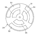
図2に示すように帯域切替フィルタ22は、通常・蛍光観察用フィルタ48、赤外観察用フィルタ49、狭帯域光観察用フィルタ50が配置されている。
【0033】
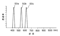
各フィルタの分光特性はそれぞれ図4、図5に示すようになっている。つまり、図4は通常・蛍光観察用フィルタ48の透過特性48a及び赤外観察用フィルタ49の透過特性49aを示し、図5は狭帯域光観察フィルタ50の透過特性50a、50b、50cを示す。
【0034】
この場合、通常・蛍光観察用フィルタ48の透過特性48aは400nm〜660nmの光を透過し、赤外観察用フィルタ49の透過特性はは790〜980nmの光を透過する。
【0035】
また図5に示すように、狭帯域光観察フィルタ50に関しては、1つのフィルタで3つの離散的な帯域を透過する3峰性の透過特性50a、50b、50cを有する。つまり400〜430nm、530〜560nm、600〜630nmの光を透過する透過特性50a、50b、50cを有する。
【0036】
回転フィルタ板24は、図3に示すように外周にそれぞれ赤、緑、青の波長の光を透過するRフィルタ51、Gフィルタ52、Bフィルタ53が配置されている。
また、回転フィルタ板24における内周には540〜560nmの光を透過するG′フィルタ54、390〜450nmの励起光を透過する励起フィルタ55、600〜620nmの光を透過するR′フィルタ56が配置されている。
【0037】
外周、内周のフィルタの分光特性はそれぞれ図6、図7に示すようになっている。つまり、図6に示すようにRフィルタ51、Gフィルタ52、Bフィルタ53はそれぞれフィルタ特性51a,52a,53aに示す透過特性を示す。
【0038】
また、図6に示すように、外周の各フィルタ51,52,53に関しては、可視光の帯域だけでなく近赤外光の帯域も部分的に透過する特性を持っている。 具体的には、Rフィルタ51及びGフィルタ52の透過特性51a及び52aは750〜820nmの光を透過する特性を有し、Bフィルタ53の透過特性53aは900nm以上の波長の光も透過する特性を有する。
【0039】
励起光カットフィルタ19は、図8に示すように450nm以下の波長の光を遮断する透過特性19aを持ち、その透過帯域は励起フィルタ55の透過帯域と重ならないようにしている。
【0040】
本実施の形態では、光源装置3には複数の観察モードに対応して、選択された観察モードに対応した照明光をスコープ2のライトガイドファイバ14に供給可能にすると共に、プロセッサ4には選択された各観察モードにおいて、その観察モードで撮像された信号に対して必要とされる信号処理を行う回路をFPGA39により、データROM47から読み出す回路データを(ロード制御回路46によるロード制御により)選択することによって、プログラマブルにその回路を構築できるようにしている。
【0041】
このような構成にすることにより、共通のFPGA39により、例えば通常観察時及び赤外光観察時には共通のFPGA39により色強調回路を、蛍光観察時にはノイズ除去回路を構築できるようにして、小さな回路規模で必要とされる信号処理を行えるようにしていることが特徴となっている。
【0042】
また、FPGA39と共に、このFPGA39を通さないで動画の表示処理を行うバイパス回路を設け、FPGA39により構築される回路とバイパス回路とをセレクタ40で選択可能とし、FPGA39により回路を構築中の場合には一時的にバイパス回路を通すことにより、FPGA39により回路を構築中の場合においても動画を表示できるようにして使い勝手を向上していることも特徴となっている。
【0043】
次に本実施の形態の作用を説明する。
光源装置3のランプ21からは、被写体を照明するための光が放射される。ランプ21から放射された光は、帯域切替フィルタ22、回転フィルタ板24を通過した後、集光レンズ27により集光されてスコープ2のライトガイドファイバ14に入射される。
【0044】
帯域切替フィルタ22は、CPU45からのフィルタ切替指示信号によってモータ23によって回転駆動され、通常観察時及び蛍光観察時には通常・蛍光観察用フィルタ48が、狭帯域光観察時には狭帯域光観察用フィルタ50が、赤外観察時には赤外観察用フィルタ49がそれぞれ照明光路上に挿入される。
【0045】
回転フィルタ板24は、通常観察時、狭帯域光観察時及び赤外観察時には外周のフィルタが光軸上に挿入され、モータ25により所定の速度で回転駆動されることにより順次Rフィルタ51、Gフィルタ52、Bフィルタ53が光路上に入れられる。
【0046】
帯域切替フィルタ22との組み合わせにより、通常観察時には赤、緑、青の光が、狭帯域光観察時には、400〜430nm、530〜560nm、600〜630nmの光が、赤外光観察時には、790〜820nm、790〜820nm、900〜980nmの光がそれぞれ透過される。
【0047】
このモータ25は、微弱な蛍光を長い露光時間で撮像するために、蛍光観察時のみは他の観察モードに比べて遅い速度で回転する。また、蛍光観察時には、回転フィルタ板24はCPU45からのフィルタ切替指示信号に応じてモータ26により照明光路と垂直な方向Aに移動されることにより、内周のフィルタが照明光路上に挿入される。
【0048】
内周のフィルタ挿入時には540〜560nm、390〜450nm、600〜620nmの波長の光が順次、光源装置3から出射される。ここで、390〜450nmの光は生体組織からの自家蛍光を励起するための励起光である。
【0049】
スコープ2のライトガイドファイバ14に入射された光は、スコープ2の先端部の照明窓から消化管等の被写体8に照射される。被写体8で散乱、反射、放射された光はスコープ2の先端部の観察窓の対物レンズ17によりCCD18上に結像され、光電変換されて撮像される。
【0050】
CCD18の前面には励起光カットフィルタ19が配置されており、390〜450nmの励起光を遮断して蛍光を抽出する作用を持つ。このCCD18は回転フィルタ板24の回転に同期して図示しないCCD駆動回路により駆動され、Rフィルタ51、Gフィルタ52、Bフィルタ53等、回転フィルタ板24のそれぞれのフィルタを透過した照射光に対応する画像信号が順次プロセッサ4に入力される。
【0051】
プロセッサ4に入力された画像信号は、まずプリプロセス回路34に入力される。プリプロセス回路34ではCDS(相関2重サンプリング)等の処理により画像信号が取り出される。
プリプロセス回路34から出力された信号はA/D変換回路35によりアナログ信号からデジタル信号に変換される。A/D変換回路35から出力された信号は、カラーバランス補正回路36に入力される。
【0052】
カラーバランス補正回路36では、基準となる被写体を撮像としたときにモニタ5に所定の色で表示されるように信号の増幅率が調整された後、第1同時化メモリ37に一時的に記憶される。この第1同時化メモリ37では、順次記憶された画像データを同時に読み出すことにより、面順次画像の同時化を行う。
【0053】
同時化された画像データは、ディレイ回路38とFPGA39とに入力される。ディレイ回路38は、FPGA39を通過する信号と同じ時間だけ遅延するようにタイミングを合わせるためのメモリである。
【0054】
ディレイ回路38及びFPGA39からの出力信号はセレクタ40に入力される。このセレクタ40では、ディレイ38から出力された信号とFPGA39から出力された信号の片方を選択すると共に、同時化された信号を再度面順次化してガンマ補正回路41に出力する。
【0055】
この面順次化は、ガンマ補正回路41や構造強調回路42の回路規模を小さくするために行われる。ガンマ補正回路41ではモニタ5のガンマ特性を補正する変換が行われ、構造強調回路42で画像の輪郭成分が強調されて第2同時化メモリ43に出力される。
【0056】
第2同時化メモリ43で再び同時化された信号は、D/A変換回路44によりアナログ信号に変換され、モニタ5に出力され、CCD18で撮像された画像が表示される。
【0057】
観察光の切替(実際に切り替えるのは照明光であるが観察光も変わるのでここではこのように記述する)は、スコープ2のフィルタ切替スイッチ20、キーボード6、フットスイッチ7、光源装置3のスイッチ31、32のいずれかを使用者が操作することにより行われる。
【0058】
キーボード6上では、通常観察、蛍光観察、狭帯域光観察、赤外観察のそれぞれを選択するためのキーがあるので、直接観察したいモードを使用者が選択することにより、対応付けられた指示信号がCPU45に入力され、CPU45はその指示信号に対応して観察光の切替制御を行う。
【0059】
スコープ2のフィルタ切替スイッチ20が押されたときには、通常観察→蛍光観察→狭帯域光観察→赤外観察→通常観察…の順に、使用者によりスイッチ20が押される毎に観察光が順次切り替わるようにCPU45は制御する。
【0060】
光源装置3の通常光・特殊光切替スイッチ31(又はフットスイッチ7におけるこれに対応するスイッチ)が押された場合には、押される前の状態が、蛍光観察、狭帯域光観察、赤外観察のいずれかの場合には、通常観察に切り替えるようにCPU45が制御する。
【0061】
押される前の状態が通常観察の場合は、蛍光観察、狭帯域光観察、赤外観察のいずれかに切り替えるようにCPU45が制御する。この場合、蛍光観察、狭帯域光観察、赤外観察のどれに切り替えられるかは、特殊光選択スイッチ32により選択することができる。
特殊光選択スイッチ32は、使用者がスイッチを押す毎に蛍光観察→狭帯域光観察→赤外観察→蛍光観察…のように3つの特殊観察モードの中の1つが選択される。
【0062】
特殊光選択スイッチ32が押される前の状態が通常観察である場合には、CPU45は観察光の切替は行わず、図示しない表示用LED表示により選択されている特殊観察モードが変わったことが分かる。特殊光選択スイッチ32が押される前の状態が通常観察ではない場合には、CPU45は実際に観察光の切替制御を行う。
【0063】
観察光の切替を行うときのCPU45による制御動作を図9に示す。
まず、CPU45は第2同時化メモリ43を制御してモニタ5に出力されるRGB信号全てに同じ信号(G信号)を割り当てることにより、モノクロ画像を出力するようにする(ステップS1)。
【0064】
そして、次のステップS2で、CPU45はセレクタ40によりディレイ回路38からの信号を選択することにより、その場合の画像信号がFPGA39を通過しないようにする。つまり、CPU45はディレイ回路38を通した画像信号を選択する。
【0065】
次のステップS3では、CPU45はモータ23、モータ26を制御するフィルタ切替指示信号を送り、フィルタ切換処理により選ばれた観察光に切り替える。
【0066】
その時、同時に、CPU45はロード制御回路46にFPGA再構成を指示(ステップS4)することにより、FPGA39を再構成する。
【0067】
ロード制御回路46では、観察光に対応したデータROM47のアドレスを指定すると共に、FPGA39に回路データを読み込むための制御を行い、データROM47から読み出された観察光に対応した回路データがFPGA39にロードされる。
【0068】
CPU45では、ロード制御回路46から再構成の終了を判断する(ステップS5)。具体的にはCPU45はFPGA39からロード終了したことの確認する信号を受けるまで待つ。さらにCPU45はステップS6でフィルタ切替終了を待ち、そのフィルタ切替終了後、ステップS7に示すようにセレクタ40によりFPGA39からの出力を選択する。
【0069】
なお、フィルタ切替終了の信号は、切替終了の信号を光源装置3から受けてもよいし、フィルタ切替終了にかかる時間以上に設定したタイマの出力信号で判断するようにしてもよい。
【0070】
そして、次のステップS8で第2同時化メモリ43を制御して再度カラー画像を出力するように制御する。
【0071】
このように、ロード中のFPGA39を迂回するバイパス回路を設けることにより、FPGA39の構成中でも、動画での観察が可能になる。FPGA39内で行う画像処理についてはバイパス通過中には行うことができないが、この時はフィルタ切替中の画像であって元々の画像の色調も正常ではないので特に問題とはならない。
【0072】
また、一応動画像を観察できるので、フィルタ切替中にスコープ2が意外な動きをしていないか等を確認することができ、使い勝手を確保することができる。また、フィルタ切替中の画像をモノクロ画像にすることにより、フィルタ切替による画像の色調の乱れを目立たないようにすることができる。
【0073】
通常光観察時、赤外光観察時にFPGA39内に構成される色強調回路60を図10に示す。
色強調回路60では、まず入力される入力画像信号(具体的にはRin、Gin、Bin)を基に、色素量算出回路61において色素量を算出する。この色素量算出回路61では、通常観察時にはヘモグロビン量を、赤外観察時にはICG量を画素ごとに算出する。
【0074】
ヘモグロビン量IHbを求める式は、
IHb=log(R/G)
で表され、ICG量IIcgを求める式は
IIcg=log(B/R)
で表される。
【0075】
また、色素量算出回路61からは、画素ごとの色素量(ヘモグロビン量またはICG量)の他に、画像1フレーム分の色素量の平均値として平均色素量も出力される。
【0076】
色素量算出回路61で算出された色素量および平均色素量は、強調係数算出回路62に入力され、色素量と平均色素量との差を基にした強調係数が画素ごとに算出される。
【0077】
通常観察時(IHb算出時)の場合、各画素ごとの強調係数αは、
α=IHb−Ave(IHb)
で表され、赤外観察時(ICG量算出時)の場合も上式のIHbの代わりにIIcgが入る以外は同様である。
【0078】
上式におけるAve(IHb)はIHbの画像1フレーム分の平均値を示す。ここで各画素の色素量と1フレーム分の平均値との差をとることにより、偏った色分布の画像でも効果的に強調することができる。
【0079】
また、入力画像信号としてのRin、Gin、Binはそれぞれディレイ回路63a、63b、63cにより遅延された後、それぞれルックアップテーブル(LUTと略記)64a、64b、64cに入力される。
【0080】
つまり、ディレイ回路63a、63b、63cを通してタイミングを調整された画像信号と、強調係数αと、CPU45から指定される色調設定レベルの値とがそれぞれLUT64a、64b、64cに入力され、これらをもとにして色素量を基にした色強調を画素ごとに行う。
【0081】
強調の式は、
Rout=Rin×exp(h×kR×α)
Gout=Gin×exp(h×kG×α)
Bout=Bin×exp(h×kB×α)
で表される。
【0082】
ここで、Rin、Gin、BinはそれぞれR,G,Bの入力画像信号、Rout、Gout、BoutはそれぞれR,G,Bの出力画像信号、kR、kG、kBは対象となる色素の色ごとの吸収率により決まる係数でIHb量を求めるときとICG量を求めるときとでは異なった値をとる。
【0083】
hは強調の度合いを表す係数であり、CPU45経由で色調設定スイッチ33から設定される設定レベルにより決定される。この強調を行うことにより、IHb量に基づく強調時には、見かけのIHb量が増えたような画像が形成され、ICG量に基づく強調時には、見かけのICG量が増えたような画像が形成される。
【0084】
通常観察時でも赤外観察時でも回路の構成は同じであるが、色素の吸収率が異なるので、LUTのデータ等は共有できない。
【0085】
しかし、本実施の形態では通常観察と赤外観察を切り替えたときでもFPGA39の再構成を行うようにしてそれぞれ必要なだけのLUT64a、64b、64cを構成しているので、回路規模を小さくすることができる。また、LUT64a、64b、64cをFPGA39内部に設けることにより、外部にROMを配置するよりも高速なアクセスが可能となっている。
【0086】
蛍光観察時にFPGA39内に構成されるノイズ除去回路70を図11に示す。
このノイズ除去回路70は3×3のメディアンフィルタで構成されており、1クロック分遅延させるディレイ回路71(具体的には71a〜71f)、約1ライン分遅延させるラインメモリ72(具体的には72a、72b)によって、対象画素の近傍の9画素の画素値が中央値選択回路73に入力されるようにしている。
【0087】
例えば入力画像信号としてのRinはそのまま中央値選択回路73に入力されると共に、ディレイ回路71aにより1画素分遅延されて中央値選択回路73に入力される。さらにこの1画素遅延された信号はディレイ回路71bにより1画素分遅延されて中央値選択回路73に入力される。
【0088】
同様に入力されるRinは、ラインメモリ72aにより約1ライン分遅延された後、中央値選択回路73に入力されると共に、ディレイ回路71a及び71bにより1画素分、2画素分それぞれ遅延されて中央値選択回路73に入力される。
【0089】
同様にラインメモリ72aにより約1ライン分遅延された信号は、ラインメモリ72bにより約1ライン分遅延された後、中央値選択回路73に入力されると共に、ディレイ回路71a及び71bにより1画素分、2画素分それぞれ遅延されて中央値選択回路73に入力される。
【0090】
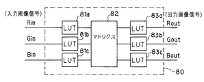
中央値選択回路73では、近傍9画素の中央値となる画素値が選択されて出力される。図11にはR信号についてのみ記載しているが、G信号、B信号についても同様であり、狭帯域光観察時にFPGA39内に構成される色変換回路80を図12に示す。
【0091】
この色変換回路80では、入力される画像信号としてのRin、Gin,Binの各信号はそれぞれLUT81a、81b、81cを通過した後、マトリクス回路82によりマトリクス演算され、さらにLUT83a、83b、83cを経て出力される。マトリクス回路82での演算は、
Rout=a1・Rin+b1・Gin+c1・Bin
Gout=a2・Rin+b2・Gin+c2・Bin
Bout=a3・Rin+b3・Gin+c3・Bin
で表される。
【0092】
a、b、cは係数であり、図示しないメモリに複数組記憶されており、色調設定スイッチ33からCPU45経由での色調設定レベルにより選択される。このように、色調設定スイッチ33は、通常観察時・赤外観察時の色強調レベルの設定と、狭帯域光観察時のマトリクス演算の係数選択とに併用されている。
【0093】
これらの設定されたレベルは各観察モード毎にCPU45で記憶されており、観察モードの切替に応じて記憶されているレベルが設定される。LUT81とLUT83は、色変換によってモニタ5に表示できない色域に出てしまう色を表示可能な範囲に圧縮するための調整を行うためのものである。
【0094】
本実施の形態では、FPGA39を用いているが、その他のPLD(Programmable Logic Device)に応用することも可能である。また、切り替えられる観察光は、自家蛍光、狭帯域光、赤外光に限らず、体内に投与可能な薬剤の蛍光やラマン光であってもよい。
また、面順次式の内視鏡装置に限らず、同時式の内視鏡装置に応用することもできる。
【0095】
また、通常観察時、赤外観察時の色強調については、特開平10−210324号公報で開示されているように、画像の特徴量に応じて強調のレベルを調整するものを用いてもよい。
【0096】
また、FPGA39、ロード制御回路46、データROM47を他の部分とは別の独立した基板上に実装し、その基板をプロセッサ4に抜き差し可能(つまり着脱可能)に構成することにより、色変換などの画像処理機能をプロセッサ4の拡張機能としてユーザに提供することも可能である。
【0097】
また、スコープ2やフットスイッチ7などに配置されるスイッチは、ユーザの設定によって様々に機能が割り当てられるものが好ましい。
【0098】
本実施の形態は以下の効果を有する。
観察光の切替に応じて、フィルタ切替中にプログラミング可能な論理素子を再構成するようにしたので、複数の観察光に対応した信号処理を、少ない回路規模で実現することができる。
【0099】
また、画像信号処理を行う論理素子の構成中には、その論理素子を通らないバイパス回路を通して信号を出力するようにしたので、プログラミング可能な論理素子の構成中においても、観察画像を動画で観察することができる。
【0100】
(第2の実施の形態)
本実施の形態の目的は複数の観察光に対応した信号処理を、少ない回路規模で実現することと、プログラミング可能な論理素子の構成中においても、観察画像の静止画表示を可能にする画像処理装置を提供することである。
【0101】
本実施の形態の構成は第1の実施の形態と同じ、つまり図1と同じ構成である。
次に本実施の形態の作用を説明する。
本実施の形態では、第1の実施の形態と観察光の切替時の動作が異なる。
【0102】
観察光の切替を行うときのCPU45の動作を図13に示す。
まず、最初のステップS11において、CPU45は第2同時化メモリ43を制御してこの第2同時化メモリ43の書き込みを禁止することにより、その書き込み禁止直前に書き込まれた画像を繰り返し読み出す状態、つまりフリーズ状態の静止画像を出力するようにする。そして、次のステップS12で、モータ23、モータ26にフィルタ切替指示信号を送り、所定の観察光に切り替える。
【0103】
その時、同時にステップS13に示すように、CPU45はロード制御回路46にFPGA再構成を指示することにより、FPGA39を再構成する。
【0104】
ロード制御回路46は、観察光に対応したデータROM47のアドレスを指定すると共に、FPGA39に回路データを読み込むための制御を行い、データROM47から読み出された観察光に対応した回路データがFPGAにロードされる。
【0105】
次のステップS14でCPU45は、ロード制御回路46からのロード終了の信号により再構成終了かの判断を行い、この信号を受けた後、さらに次のステップS15でフィルタ切替終了かの判断を行う。このフィルタ切替終了の後CPU45は、第2同時化メモリ43を制御してフリーズを解除することにより再度動画像を出力する(ステップS16)。
【0106】
このように、FPGA39のロード中に画像をフリーズさせることにより、FPGA39の構成中でも、カラーの静止画での観察が可能になり、フィルタ切替による画像の乱れも起きない。
【0107】
また、FPGA39の再構成中は動画の観察をすることはできないが、フィルタの切替中に行われることであるので、FPGA39の再構成により検査時間が長引くなどの弊害はない。
【0108】
本実施の形態は以下の効果を有する。
観察光の切替に応じて、フィルタ切替中にプログラミング可能な論理素子を再構成するようにしたので、複数の観察光に対応した信号処理を、少ない回路規模で実現することができる。
【0109】
また、画像信号処理を行う論理素子の構成中には、その論理素子よりも出力に近い部分で画像を静止させて出力するようにしたので、プログラミング可能な論理素子の構成中においても、乱れの無い静止画で観察することができる。
【0110】
[付記]
1.波長帯域の異なる複数の照明光を選択的に供給する照明光供給装置と、
この照明光供給装置により照明された被写体を撮像する撮像素子と、
前記撮像素子から出力される信号を信号処理するための、回路データに基づいて回路を構成することが可能なプログラマブル回路と、
前記回路データを前記複数の照明光に対応して複数記憶する回路データ記憶回路と、
前記複数の照明光を切り替えるための照明光切替指示手段と、
前記照明光切替指示手段の指示に応じて照明光を切り替えるとともに切り替え後の照明光に対応した前記回路データを読み出して前記プログラマブル回路にロードする制御回路を備えたことを特徴とする電子内視鏡装置。
【0111】
2.前記撮像手段から出力される信号を前記プログラマブル回路を通らずに表示装置に導くバイパス回路を有し、
前記バイパス回路を通過した信号を前記プログラマブル回路のロード中に前記表示装置に導くことを特徴とする電子内視鏡装置。
(付記2の目的)プログラミング可能な論理素子の構成中においても、観察画像の動画表示を可能にする電子内視鏡装置を提供すること。
【0112】
3.前記プログラマブル回路から出力される信号を記憶する静止画像記憶回路を有し、
前記静止画像記憶回路に記憶された静止画像信号を前記プログラマブル回路のロード中に表示装置に導くことを特徴とする電子内視鏡装置。
(付記3の目的)プログラミング可能な論理素子の構成中においても、観察画像の静止画表示を可能にする電子内視鏡装置を提供すること。
【0113】
4.複数の照明光を選択的に発生する照明光発生手段による照明光を被写体に照射して撮像し、得られた前記照明光に基づく撮像信号を、回路データに基づいてプログラマブルに構築されるプログラマブル回路により信号処理するプログラマブル回路構築手段と、
複数種類の回路データを保持する回路データ保持手段と、
前記照明光発生手段が発生する照明光に対応して前記プログラマブル回路手段が使用する回路データを前記回路データ保持手段が保持する複数種類の回路データから選択する制御手段と、
を備えたことを特徴とする画像処理装置。
【0114】
【発明の効果】
以上説明したように本発明によれば、複数の観察光に対応した信号処理を、少ない回路規模で実現することができる。
【図面の簡単な説明】
【図1】本発明の第1の実施の形態を備えた内視鏡装置の全体構成図。
【図2】帯域切替フィルタの説明図。
【図3】回転フィルタ板の説明図。
【図4】通常・蛍光観察フィルタ、赤外観察フィルタの透過特性を示す図。
【図5】狭帯域光観察フィルタの透過特性を示す図。
【図6】R,G,Bフィルタの透過特性を示す図。
【図7】励起、G′、R′フィルタの透過特性を示す図。
【図8】励起光カットフィルタの透過特性を示す図。
【図9】第1の実施の形態に係るフィルタ切替時の動作説明図。
【図10】FPGAにより構成される色強調回路の構成図。
【図11】FPGAにより構成されるノイズ除去回路の構成図。
【図12】FPGAにより構成される色変換回路の構成図。
【図13】本発明の第2の実施の形態に係るフィルタ切替時の動作説明図。
【符号の説明】
1…内視鏡装置
2…電子内視鏡(スコープ)
3…光源装置
4…プロセッサ
5…モニタ
6…キーボード
7…フットスイッチ
8…被写体
11…挿入部
14…ライトガイドファイバ
17…対物レンズ
18…CCD
19…励起光カットフィルタ
20…フィルタ切替スイッチ
21…ランプ
22…帯域切替フィルタ
23,25,26…モータ
24…回転フィルタ
31…通常光・特殊光切替スイッチ
32…特殊光選択スイッチ
39…FPGA
45…CPU
46…ロード制御回路
47…データROM
48…通常・蛍光観察用フィルタ
49…狭帯域光観察用フィルタ
50…赤外観察用フィルタ
51…Rフィルタ
52…Gフィルタ
53…Bフィルタ
54…G′フィルタ
55…励起フィルタ
56…B′フィルタ[0001]
BACKGROUND OF THE INVENTION
The present invention relates to an image processing apparatus that enables observation with a plurality of types of observation light.
[0002]
[Prior art]
Currently, by inserting a scope into the body cavity, the gastrointestinal tract such as the esophagus, stomach, small intestine, and large intestine, and the trachea such as the lung are observed, and if necessary, various treatment tools are inserted into the treatment instrument channel. Electronic endoscopes that can be treated are widely used.
In particular, light such as red, green, and blue is emitted from the light source device through an optical filter to the subject and received by a monochrome image sensor, and signal processing is performed in the processor and output to the display device as a color image. The field sequential type endoscope apparatus is widely spread in Japan.
[0003]
Signal processing within the processor includes color enhancement that is performed to facilitate the detection of lesions. In color enhancement, the normal mucosa and the lesioned mucosa are clearly distinguished from each other by the color difference by emphasizing the color based on the amount of hemoglobin contained in the living mucosa.
[0004]
In addition, in the diagnosis using an endoscope, in addition to normal observation in which a color image similar to that seen with the naked eye is displayed on a monitor, autofluorescence observation using autofluorescence of living tissue has begun to be performed. In autofluorescence observation, diagnosis is performed using the fact that the spectrum of autofluorescence emitted from a living tissue when ultraviolet to blue excitation light is applied to the living tissue differs between a normal mucosa and a tumor.
[0005]
This autofluorescence image is displayed on the monitor with a different color assigned to the reflected light image reflected back from the living tissue, so that the lesion can be clearly recognized as a color difference from the normal part. It becomes like this. Since the fluorescence is weak, the fluorescence image contains a lot of noise, and the processor for fluorescence observation is often equipped with a noise removal circuit.
[0006]
In addition, as disclosed in, for example, Japanese Patent Application Laid-Open No. 2002-95635, narrow band light observation (NBI) is performed in which observation is performed by irradiating light in a narrower band than normal observation light. ing. In narrow-band light observation, blood vessels on the surface of the mucosa can be observed with higher contrast.
[0007]
Since this narrow-band light observation is performed with narrow-band light, an image having a color tone different from that of a normal endoscopic image is displayed. Therefore, color adjustment is performed by providing a color conversion circuit in the processor, and after conversion to a color tone more suitable for lesion determination, the color is output and displayed on a monitor.
[0008]
Infrared observation is also performed in which observation is performed by irradiating near infrared light. During infrared observation, indocyanine green (ICG), a drug that absorbs in the near infrared, is injected into blood vessels, making it possible to observe hemodynamics in the deep submucosal region that cannot be seen with normal observation. . Also during this infrared observation, a blood vessel image with better contrast can be observed by performing color enhancement processing based on the amount of ICG contained in the mucous membrane.
[0009]
These normal observation, fluorescence observation, narrow band light observation, and infrared observation can be combined into one system by using an illumination device capable of switching illumination light.
[0010]
[Patent Document 1]
JP 2002-95635 A
[0011]
[Problems to be solved by the invention]
In a conventional electronic endoscope apparatus or processor, when performing observation processing corresponding to a plurality of types of observation light (observation mode) such as normal observation, fluorescence observation, narrow-band light observation, and infrared observation in one processor Since all the image processing functions such as color enhancement, noise removal, and color conversion necessary for each of them are installed, the circuit scale has become very large.
[0012]
As a device for reducing the circuit scale of an endoscope apparatus, a programmable logic element is configured for each CCD mounted on a connected endoscope as disclosed in Japanese Patent Laid-Open No. 5-277005. Some of them share a circuit.
However, since this technology automatically configures logic elements when observation is not performed, such as when the endoscope device is not turned on, it can be operated by the user during inspection. Corresponding logic elements could not be constructed.
[0013]
Further, if the logic element is configured during observation, signal processing cannot be performed while the logic element is being configured, and the image on the monitor disappears.
[0014]
Also, in order to switch the illumination light when switching the observation mode, the rotation speed of the rotary filter is changed or the position of the filter is moved, so that the color of the image is disturbed or the brightness of the image is not constant, etc. The problem was occurring.
[0015]
(Object of invention)
The present invention has been made in view of the above points, and an object of the present invention is to provide an image processing apparatus capable of realizing signal processing corresponding to a plurality of observation lights with a small circuit scale.
[0016]
[Means and Actions for Solving the Problems]
The image processing apparatus of the present inventionIllumination light supply means for selectively supplying a plurality of illumination lights having different wavelength regions;
Programmable circuit means for supplying an image of illumination light from the illumination light supply means to a subject and imaging the obtained imaging signal based on the obtained illumination light by a circuit that is programmable based on circuit data;
Circuit data holding means having a plurality of types of circuit data;
Control means for selecting circuit data used by the programmable circuit means corresponding to the illumination light supplied by the illumination light supply means from circuit data of the circuit data holding means;
Illumination light switching instruction means for giving an instruction to switch the plurality of illumination lights;
Have
The control means selectively switches the illumination light according to an instruction from the illumination light switching means, and the illumination light switching means from the plurality of types of circuit data of the circuit data holding means to the programmable circuit means. Control to construct a circuit using circuit data corresponding to the illumination light instructed to switch to a bypass circuit that bypasses the circuit and performs display processing on the imaging signal during the construction of the circuit, and the bypass Performs switching control to display the moving image generated through the circuit on the display means.By selecting and using circuit data from multiple types by programmable circuit means, a circuit that performs signal processing according to illumination lightSmallIt can be realized with a large circuit scale.
[0017]
DETAILED DESCRIPTION OF THE INVENTION
Embodiments of the present invention will be described below with reference to the drawings.
(First embodiment)
1 to 12 relate to a first embodiment of the present invention, FIG. 1 shows the overall configuration of an endoscope apparatus provided with the first embodiment, FIG. 2 shows a band switching filter, 3 shows the rotation filter plate, FIG. 4 shows the transmission characteristics of the normal / fluorescence observation filter and the infrared observation filter, FIG. 5 shows the transmission characteristics of the narrow-band light observation filter, and FIG. 6 shows the R, G and B filters. 7 shows the transmission characteristics of the excitation, G ′ and R ′ filters, FIG. 8 shows the transmission characteristics of the excitation light cut filter, FIG. 9 shows the operation explanation at the time of filter switching, and FIG. FIG. 11 shows the configuration of a color enhancement circuit composed of FPGA during normal light and infrared light observation, FIG. 11 shows the configuration of a noise removal circuit composed of FPGA during fluorescence observation, and FIG. 12 shows the configuration of FPGA during narrow band light observation. The function of the color conversion circuit comprised by these is shown.
[0018]
The purpose of this embodiment is to realize signal processing corresponding to a plurality of observation lights (observation modes) with a small circuit scale and to display a moving image of an observation image even during the configuration (construction) of a programmable logic element. An object of the present invention is to provide an image processing apparatus and an electronic endoscope apparatus that enable this.
[0019]
First, the configuration of the present embodiment will be described.
As shown in FIG. 1, an
[0020]
The
[0021]
A
[0022]
The illumination light transmitted by the
[0023]
An
[0024]
An excitation light cut
In addition, the
[0025]
The light source device 3 includes a
[0026]
In this case, a
[0027]
Further, for example, on the front panel of the light source device 3, a normal light / special
[0028]
The
[0029]
The
[0030]
In addition, the
[0031]
The
The
[0032]
The
As shown in FIG. 2, the
[0033]
The spectral characteristics of each filter are as shown in FIGS. 4 shows the transmission characteristic 48a of the normal /
[0034]
In this case, the transmission characteristic 48a of the normal /
[0035]
As shown in FIG. 5, the narrow-band light observation filter 50 has three-
[0036]
As shown in FIG. 3, the
Further, on the inner periphery of the
[0037]
The spectral characteristics of the outer and inner filters are shown in FIGS. 6 and 7, respectively. That is, as shown in FIG. 6, the
[0038]
As shown in FIG. 6, each of the
[0039]
As shown in FIG. 8, the excitation light cut
[0040]
In the present embodiment, the light source device 3 can supply illumination light corresponding to the selected observation mode to the
[0041]
With such a configuration, a
[0042]
In addition to the
[0043]
Next, the operation of this embodiment will be described.
Light for illuminating the subject is emitted from the
[0044]
The
[0045]
The
[0046]
In combination with the
[0047]
The
[0048]
When the inner peripheral filter is inserted, light having wavelengths of 540 to 560 nm, 390 to 450 nm, and 600 to 620 nm are sequentially emitted from the light source device 3. Here, light of 390 to 450 nm is excitation light for exciting autofluorescence from living tissue.
[0049]
The light incident on the
[0050]
An excitation light cut
[0051]
The image signal input to the
The signal output from the
[0052]
In the color
[0053]
The synchronized image data is input to the
[0054]
Output signals from the
[0055]
This frame ordering is performed to reduce the circuit scale of the gamma correction circuit 41 and the
[0056]
The signal synchronized again in the
[0057]
The observation light is switched (the actual switching is the illumination light, but the observation light also changes, so it is described here): the
[0058]
On the
[0059]
When the
[0060]
When the normal light / special light switch 31 (or the corresponding switch in the foot switch 7) of the light source device 3 is pressed, the state before being pressed is fluorescence observation, narrow band light observation, infrared observation. In either case, the
[0061]
When the state before pressing is normal observation, the
Each time the user presses the special
[0062]
When the state before the special
[0063]
FIG. 9 shows a control operation by the
First, the
[0064]
In the next step S <b> 2, the
[0065]
In the next step S3, the
[0066]
At the same time, the
[0067]
The
[0068]
The
[0069]
The filter switching end signal may be received from the light source device 3 as a switching end signal, or may be determined by a timer output signal set to be equal to or longer than the time required for the filter switching end.
[0070]
In the next step S8, the
[0071]
In this way, by providing a bypass circuit that bypasses the
[0072]
In addition, since a moving image can be observed, it is possible to confirm whether the
[0073]
FIG. 10 shows a color emphasis circuit 60 configured in the
In the color enhancement circuit 60, first, a dye amount is calculated in a dye
[0074]
The formula for determining the amount of hemoglobin IHb is:
IHb = log (R / G)
The formula for obtaining the ICG amount IIcg is
IIcg = log (B / R)
It is represented by
[0075]
In addition to the dye amount (hemoglobin amount or ICG amount) for each pixel, the dye
[0076]
The pigment amount and average pigment amount calculated by the pigment
[0077]
In normal observation (IHb calculation), the enhancement coefficient α for each pixel is
α = IHb−Ave (IHb)
The same applies to infrared observation (ICG amount calculation) except that IIcg is entered instead of IHb in the above formula.
[0078]
Ave (IHb) in the above equation indicates an average value for one frame of an IHb image. Here, by taking the difference between the dye amount of each pixel and the average value for one frame, it is possible to effectively enhance even an image having a biased color distribution.
[0079]
Rin, Gin, and Bin as input image signals are delayed by
[0080]
In other words, the image signal whose timing is adjusted through the
[0081]
The emphasis formula is
Rout = Rin × exp (h × kR × α)
Gout = Gin × exp (h × kG × α)
Bout = Bin × exp (h × kB × α)
It is represented by
[0082]
Here, Rin, Gin, and Bin are R, G, and B input image signals, Rout, Gout, and Bout are R, G, and B output image signals, respectively, and kR, kG, and kB are the colors of the target dyes. When the IHb amount is determined by a coefficient determined by the absorption rate, the ICG amount is different.
[0083]
h is a coefficient representing the degree of emphasis, and is determined by the setting level set from the color tone setting switch 33 via the
[0084]
Although the circuit configuration is the same during normal observation and infrared observation, the LUT data and the like cannot be shared because the dye absorption rate is different.
[0085]
However, in the present embodiment, the
[0086]
A
The
[0087]
For example, Rin as an input image signal is input to the median
[0088]
Similarly, the input Rin is delayed by about one line by the line memory 72a and then input to the median
[0089]
Similarly, the signal delayed by about one line by the line memory 72a is delayed by about one line by the
[0090]
The median
[0091]
In this
Rout = a1, Rin + b1, Gin + c1, Bin
Gout = a2, Rin + b2, Gin + c2, Bin
Bout = a3 ・ Rin + b3 ・ Gin + c3 ・ Bin
It is represented by
[0092]
a, b, and c are coefficients, and a plurality of sets are stored in a memory (not shown), and are selected from the color tone setting switch 33 by the color tone setting level via the
[0093]
These set levels are stored in the
[0094]
In this embodiment, the
Further, the present invention can be applied not only to a field sequential endoscope apparatus but also to a simultaneous endoscope apparatus.
[0095]
As for color enhancement at the time of normal observation and infrared observation, as disclosed in Japanese Patent Laid-Open No. 10-210324, an apparatus that adjusts the enhancement level according to the feature amount of the image may be used. .
[0096]
Further, the
[0097]
In addition, it is preferable that the switches arranged in the
[0098]
The present embodiment has the following effects.
Since programmable logic elements are reconfigured during filter switching according to switching of observation light, signal processing corresponding to a plurality of observation lights can be realized with a small circuit scale.
[0099]
In addition, during the configuration of a logic element that performs image signal processing, a signal is output through a bypass circuit that does not pass through the logic element. can do.
[0100]
(Second Embodiment)
The purpose of this embodiment is to realize signal processing corresponding to a plurality of observation lights with a small circuit scale, and image processing that enables still image display of an observation image even in the configuration of a programmable logic element Is to provide a device.
[0101]
The configuration of this embodiment is the same as that of the first embodiment, that is, the same configuration as FIG.
Next, the operation of this embodiment will be described.
In the present embodiment, the operation at the time of switching the observation light is different from that in the first embodiment.
[0102]
FIG. 13 shows the operation of the
First, in the first step S11, the
[0103]
At the same time, as shown in step S13, the
[0104]
The
[0105]
In the next step S14, the
[0106]
As described above, by freezing the image while the
[0107]
Although the moving image cannot be observed during the reconstruction of the
[0108]
The present embodiment has the following effects.
Since programmable logic elements are reconfigured during filter switching according to switching of observation light, signal processing corresponding to a plurality of observation lights can be realized with a small circuit scale.
[0109]
In addition, during the configuration of the logic element that performs image signal processing, the image is stopped and output at a portion closer to the output than the logic element, so that even when the programmable logic element is configured, disturbances may occur. It can be observed with no still image.
[0110]
[Appendix]
1. An illumination light supply device that selectively supplies a plurality of illumination lights having different wavelength bands;
An image sensor for imaging a subject illuminated by the illumination light supply device;
A programmable circuit capable of configuring a circuit based on circuit data for signal processing a signal output from the image sensor;
A circuit data storage circuit for storing a plurality of the circuit data corresponding to the plurality of illumination lights;
Illumination light switching instruction means for switching the plurality of illumination lights;
An electronic endoscope comprising a control circuit that switches illumination light in accordance with an instruction from the illumination light switching instruction unit and reads the circuit data corresponding to the illumination light after switching and loads the circuit data into the programmable circuit. apparatus.
[0111]
2. A bypass circuit that guides a signal output from the imaging means to a display device without passing through the programmable circuit;
An electronic endoscope apparatus, wherein a signal that has passed through the bypass circuit is guided to the display device during loading of the programmable circuit.
(Purpose of Supplementary Note 2) To provide an electronic endoscope apparatus capable of displaying a moving image of an observation image even in a configuration of a programmable logic element.
[0112]
3. A still image storage circuit for storing a signal output from the programmable circuit;
An electronic endoscope apparatus, wherein a still image signal stored in the still image storage circuit is guided to a display device during loading of the programmable circuit.
(Purpose of Supplementary Note 3) To provide an electronic endoscope apparatus capable of displaying a still image of an observation image even in a configuration of a programmable logic element.
[0113]
4). A programmable circuit configured to irradiate a subject with illumination light by an illumination light generation unit that selectively generates a plurality of illumination lights and to image the image, and to program an imaging signal based on the obtained illumination light based on circuit data Programmable circuit construction means for signal processing by,
Circuit data holding means for holding a plurality of types of circuit data;
Control means for selecting circuit data used by the programmable circuit means corresponding to the illumination light generated by the illumination light generating means from a plurality of types of circuit data held by the circuit data holding means;
An image processing apparatus comprising:
[0114]
【The invention's effect】
As described above, according to the present invention, signal processing corresponding to a plurality of observation lights can be realized with a small circuit scale.
[Brief description of the drawings]
FIG. 1 is an overall configuration diagram of an endoscope apparatus provided with a first embodiment of the present invention.
FIG. 2 is an explanatory diagram of a band switching filter.
FIG. 3 is an explanatory diagram of a rotary filter plate.
FIG. 4 is a diagram showing transmission characteristics of a normal / fluorescence observation filter and an infrared observation filter.
FIG. 5 is a diagram showing transmission characteristics of a narrow-band light observation filter.
FIG. 6 is a diagram showing transmission characteristics of R, G, and B filters.
FIG. 7 is a graph showing transmission characteristics of excitation, G ′, and R ′ filters.
FIG. 8 is a diagram showing transmission characteristics of an excitation light cut filter.
FIG. 9 is an operation explanatory diagram at the time of filter switching according to the first embodiment;
FIG. 10 is a configuration diagram of a color enhancement circuit configured by an FPGA.
FIG. 11 is a configuration diagram of a noise removal circuit configured by an FPGA.
FIG. 12 is a configuration diagram of a color conversion circuit configured by an FPGA.
FIG. 13 is an operation explanatory view at the time of filter switching according to the second embodiment of the present invention.
[Explanation of symbols]
1. Endoscope device
2 ... Electronic endoscope (scope)
3. Light source device
4 ... Processor
5 ... Monitor
6 ... Keyboard
7 ... Foot switch
8 ... Subject
11 ... Insertion part
14 ... Light guide fiber
17 ... Objective lens
18 ... CCD
19 ... Excitation light cut filter
20 ... Filter changeover switch
21 ... Ramp
22: Band switching filter
23, 25, 26 ... motor
24 ... Rotation filter
31 ... Normal light / Special light switch
32 ... Special light selection switch
39 ... FPGA
45 ... CPU
46. Load control circuit
47 ... Data ROM
48 ... Normal / fluorescence observation filter
49 ... Narrow band light observation filter
50. Infrared observation filter
51 ... R filter
52 ... G filter
53 ... B filter
54 ... G 'filter
55 ... Excitation filter
56 ... B 'filter
Claims (3)
前記照明光供給手段による照明光を被写体に供給して撮像し、得られた前記照明光に基づく撮像信号を、回路データに基づいてプログラマブルに構築される回路により信号処理するプログラマブル回路手段と、
複数種類の回路データを有する回路データ保持手段と、
前記照明光供給手段の供給する照明光に対応して前記プログラマブル回路手段が使用する回路データを前記回路データ保持手段が有する回路データから選択する制御手段と、
前記複数の照明光を切り換えるための指示をする照明光切換指示手段と、
を有し、
前記制御手段は、前記照明光切換手段の指示に応じ、前記照明光を選択的に切り換えると共に、前記プログラマブル回路手段に対して、前記回路データ保持手段の複数種類の回路データから前記照明光切換手段の指示の照明光に対応した回路データを用いて回路を構築させる制御を行い、前記回路の構築中の期間、前記回路をバイパスして前記撮像信号に対する表示処理を行うバイパス回路に切り換え、前記バイパス回路を通して生成された動画像を表示手段に表示させる切り換え制御を行うことを特徴とする画像処理装置。Illumination light supply means for selectively supplying a plurality of illumination lights having different wavelength regions;
Programmable circuit means for supplying an image of illumination light from the illumination light supply means to a subject and imaging the obtained imaging signal based on the obtained illumination light by a circuit that is programmable based on circuit data;
Circuit data holding means having a plurality of types of circuit data;
Control means for selecting circuit data used by the programmable circuit means corresponding to the illumination light supplied by the illumination light supply means from circuit data of the circuit data holding means;
Illumination light switching instruction means for giving an instruction to switch the plurality of illumination lights;
Have
The control means selectively switches the illumination light according to an instruction from the illumination light switching means, and the illumination light switching means from the plurality of types of circuit data of the circuit data holding means to the programmable circuit means. Control to construct a circuit using circuit data corresponding to the illumination light instructed to switch to a bypass circuit that bypasses the circuit and performs display processing on the imaging signal during the construction of the circuit, and the bypass An image processing apparatus for performing switching control for displaying a moving image generated through a circuit on a display means .
Priority Applications (5)
| Application Number | Priority Date | Filing Date | Title |
|---|---|---|---|
| JP2003185715A JP4388318B2 (en) | 2003-06-27 | 2003-06-27 | Image processing device |
| DE602004022358T DE602004022358D1 (en) | 2003-06-27 | 2004-06-22 | Image processing device |
| US10/873,949 US7479990B2 (en) | 2003-06-27 | 2004-06-22 | Programmable image processing unit which displays a tentative image during programming |
| EP04014582A EP1491132B1 (en) | 2003-06-27 | 2004-06-22 | Image processing device |
| CN200410062037.3A CN100473153C (en) | 2003-06-27 | 2004-06-28 | image processing device |
Applications Claiming Priority (1)
| Application Number | Priority Date | Filing Date | Title |
|---|---|---|---|
| JP2003185715A JP4388318B2 (en) | 2003-06-27 | 2003-06-27 | Image processing device |
Related Child Applications (1)
| Application Number | Title | Priority Date | Filing Date |
|---|---|---|---|
| JP2009112875A Division JP4951649B2 (en) | 2009-05-07 | 2009-05-07 | Image processing device |
Publications (2)
| Publication Number | Publication Date |
|---|---|
| JP2005013611A JP2005013611A (en) | 2005-01-20 |
| JP4388318B2 true JP4388318B2 (en) | 2009-12-24 |
Family
ID=33411160
Family Applications (1)
| Application Number | Title | Priority Date | Filing Date |
|---|---|---|---|
| JP2003185715A Expired - Fee Related JP4388318B2 (en) | 2003-06-27 | 2003-06-27 | Image processing device |
Country Status (5)
| Country | Link |
|---|---|
| US (1) | US7479990B2 (en) |
| EP (1) | EP1491132B1 (en) |
| JP (1) | JP4388318B2 (en) |
| CN (1) | CN100473153C (en) |
| DE (1) | DE602004022358D1 (en) |
Families Citing this family (68)
| Publication number | Priority date | Publication date | Assignee | Title |
|---|---|---|---|---|
| JP4786910B2 (en) * | 2005-02-07 | 2011-10-05 | Hoya株式会社 | Electronic endoscope |
| JP4647346B2 (en) | 2005-03-04 | 2011-03-09 | 富士フイルム株式会社 | Endoscope device |
| US7850599B2 (en) | 2005-03-04 | 2010-12-14 | Fujinon Corporation | Endoscope apparatus |
| WO2006120798A1 (en) * | 2005-05-12 | 2006-11-16 | Olympus Medical Systems Corp. | Biometric instrument |
| KR100988113B1 (en) * | 2005-05-13 | 2010-10-18 | 올림푸스 메디칼 시스템즈 가부시키가이샤 | Biological observation device |
| JP4500207B2 (en) * | 2005-05-13 | 2010-07-14 | オリンパスメディカルシステムズ株式会社 | Biological observation device |
| WO2006132191A1 (en) | 2005-06-08 | 2006-12-14 | Olympus Medical Systems Corp. | Endoscope and image processing device |
| JP5063872B2 (en) * | 2005-07-04 | 2012-10-31 | オリンパスメディカルシステムズ株式会社 | Electronic endoscope device |
| JP3993618B2 (en) * | 2005-06-21 | 2007-10-17 | オリンパスメディカルシステムズ株式会社 | Electronic endoscope device |
| EP2305096B1 (en) | 2005-06-21 | 2013-06-05 | Olympus Medical Systems Corp. | Electronic endoscopic apparatus |
| JP2007000373A (en) * | 2005-06-23 | 2007-01-11 | Olympus Medical Systems Corp | Electronic endoscope |
| JP4855728B2 (en) * | 2005-07-27 | 2012-01-18 | オリンパスメディカルシステムズ株式会社 | Illumination device and observation device |
| JP2007096633A (en) * | 2005-09-28 | 2007-04-12 | Matsushita Electric Ind Co Ltd | Video signal processing apparatus and digital camera |
| GB0606891D0 (en) * | 2006-04-05 | 2006-05-17 | Council Cent Lab Res Councils | Raman Analysis Of Pharmaceutical Tablets |
| CN101116014B (en) | 2005-12-09 | 2011-09-21 | 索尼株式会社 | Surface light emitting device and liquid crystal display |
| JP4643481B2 (en) | 2006-03-23 | 2011-03-02 | オリンパスメディカルシステムズ株式会社 | Image processing device |
| EP2005877B1 (en) * | 2006-04-12 | 2014-01-08 | Olympus Medical Systems Corp. | Endoscope device |
| JP5355846B2 (en) | 2006-05-08 | 2013-11-27 | オリンパスメディカルシステムズ株式会社 | Endoscope image processing device |
| JP4847250B2 (en) * | 2006-08-03 | 2011-12-28 | オリンパスメディカルシステムズ株式会社 | Endoscope device |
| JP4868976B2 (en) * | 2006-08-18 | 2012-02-01 | オリンパスメディカルシステムズ株式会社 | Endoscope device |
| JP2008067780A (en) * | 2006-09-12 | 2008-03-27 | Olympus Medical Systems Corp | Endoscope device |
| KR100779918B1 (en) * | 2006-09-28 | 2007-11-29 | 아진산업(주) | Image processing device for stereo vision inspection and inspection method using the same |
| JP4931199B2 (en) | 2006-09-29 | 2012-05-16 | 富士フイルム株式会社 | Electronic endoscope device |
| US8498695B2 (en) | 2006-12-22 | 2013-07-30 | Novadaq Technologies Inc. | Imaging system with a single color image sensor for simultaneous fluorescence and color video endoscopy |
| KR101289799B1 (en) * | 2007-09-04 | 2013-07-26 | 삼성테크윈 주식회사 | Video presenting system having embedded operationg system and there of driving method |
| US20090059094A1 (en) * | 2007-09-04 | 2009-03-05 | Samsung Techwin Co., Ltd. | Apparatus and method for overlaying image in video presentation system having embedded operating system |
| WO2009081498A1 (en) | 2007-12-26 | 2009-07-02 | Shimadzu Corporation | Organism image capturing device |
| JP4983929B2 (en) * | 2007-12-26 | 2012-07-25 | 株式会社島津製作所 | Biological image acquisition device |
| US9173554B2 (en) | 2008-03-18 | 2015-11-03 | Novadaq Technologies, Inc. | Imaging system for combined full-color reflectance and near-infrared imaging |
| US20110059023A1 (en) * | 2008-03-19 | 2011-03-10 | Tunnell James W | Narrowband imaging using near-infrared absorbing nanoparticles |
| EP3501384B1 (en) | 2008-05-20 | 2024-07-17 | University Health Network | Method for fluorescence-based imaging and monitoring |
| DE102008027905A1 (en) * | 2008-06-12 | 2009-12-17 | Olympus Winter & Ibe Gmbh | Method and endoscope for improving endoscope images |
| JP5242316B2 (en) * | 2008-09-26 | 2013-07-24 | 富士フイルム株式会社 | Method of operating narrowband image acquisition system and narrowband image acquisition system |
| EP2228003A1 (en) * | 2009-03-13 | 2010-09-15 | Jürgen Blume | Multifunctional endoscopic device and methods employing said device |
| JP5289120B2 (en) * | 2009-03-18 | 2013-09-11 | 富士フイルム株式会社 | Endoscope system and processor device for endoscope |
| US8734333B2 (en) | 2009-03-18 | 2014-05-27 | Fujifilm Corporation | Endoscope system, endoscope video processor and method of driving endoscope system |
| JP5283545B2 (en) * | 2009-03-18 | 2013-09-04 | 富士フイルム株式会社 | Endoscope system and processor device for endoscope |
| JP5541914B2 (en) * | 2009-12-28 | 2014-07-09 | オリンパス株式会社 | Image processing apparatus, electronic apparatus, program, and operation method of endoscope apparatus |
| JP5587020B2 (en) * | 2010-04-19 | 2014-09-10 | 富士フイルム株式会社 | Endoscope apparatus, operation method and program for endoscope apparatus |
| JP5405445B2 (en) * | 2010-12-17 | 2014-02-05 | 富士フイルム株式会社 | Endoscope device |
| CN107582016B (en) | 2011-03-08 | 2020-04-28 | 诺瓦达克技术公司 | Full Spectrum LED Illuminator |
| JP5451802B2 (en) * | 2011-04-01 | 2014-03-26 | 富士フイルム株式会社 | Electronic endoscope system and calibration method for electronic endoscope system |
| WO2012140970A1 (en) * | 2011-04-11 | 2012-10-18 | オリンパスメディカルシステムズ株式会社 | Endoscope device |
| CN103732117B (en) * | 2011-12-07 | 2016-03-09 | 奥林巴斯株式会社 | endoscopic device |
| JP5829122B2 (en) * | 2011-12-27 | 2015-12-09 | オリンパス株式会社 | Imaging apparatus and evaluation value generation apparatus |
| DE102012208324B3 (en) * | 2012-05-18 | 2013-11-21 | Leica Microsystems Cms Gmbh | Circuit and method for controlling a microscope |
| JP5767163B2 (en) * | 2012-05-18 | 2015-08-19 | 株式会社日立ハイテクノロジーズ | Image processing system and image processing method |
| JP5996287B2 (en) | 2012-06-12 | 2016-09-21 | オリンパス株式会社 | Imaging device, microscope device, endoscope device |
| CN103082983B (en) * | 2013-01-04 | 2015-03-04 | 苏州康多机器人有限公司 | Laparoscope three-dimension monitoring system |
| CN108109134B (en) * | 2013-10-28 | 2021-12-03 | 富士胶片株式会社 | Image processing apparatus and method for operating the same |
| WO2015083684A1 (en) * | 2013-12-06 | 2015-06-11 | オリンパス株式会社 | Imaging device and imaging device operation method |
| PL3171765T3 (en) | 2014-07-24 | 2022-01-03 | University Health Network | Collection and analysis of data for diagnostic purposes |
| WO2016023846A2 (en) | 2014-08-15 | 2016-02-18 | Sanofi-Aventis Deutschland Gmbh | An injection device and a supplemental device configured for attachment thereto |
| ES2750856T3 (en) * | 2015-05-13 | 2020-03-27 | Nippon Steel Corp | Form inspection method, form inspection apparatus, and program |
| JP6743137B2 (en) | 2015-11-13 | 2020-08-19 | ノバダック テクノロジーズ ユーエルシー | System and method for target illumination and imaging |
| EP3408654B1 (en) | 2016-01-26 | 2022-08-03 | Stryker European Operations Limited | Fluorescence imaging system and method for fluorescence imaging |
| USD916294S1 (en) | 2016-04-28 | 2021-04-13 | Stryker European Operations Limited | Illumination and imaging device |
| EP3469420A4 (en) | 2016-06-14 | 2020-02-12 | Novadaq Technologies ULC | METHODS AND SYSTEMS FOR ADAPTIVE IMAGING FOR THE AMPLIFICATION OF A WEAK LIGHT SIGNAL IN A MEDICAL VISUALIZATION |
| JP2017225648A (en) * | 2016-06-23 | 2017-12-28 | Hoya株式会社 | Electronic endoscope system |
| CN109475270B (en) * | 2016-11-01 | 2021-04-27 | 奥林巴斯株式会社 | In vivo observation system |
| CN106618458B (en) * | 2017-01-22 | 2019-02-26 | 鹰利视医疗科技有限公司 | A kind of multi-spectrum endoscopic imaging device |
| JP6931705B2 (en) | 2017-02-10 | 2021-09-08 | ノバダック テクノロジーズ ユーエルシー | Open Field Handheld Fluorescence Imaging Systems and Methods |
| WO2020150494A1 (en) | 2019-01-17 | 2020-07-23 | Stryker Corporation | Systems and methods for medical imaging using a rolling shutter imager |
| CN110123247B (en) * | 2019-04-09 | 2021-12-28 | 苏州西能捷科技发展有限公司 | Nasosinusitis detection system |
| US11166623B2 (en) * | 2019-04-23 | 2021-11-09 | Arthrex, Inc. | Field stop fluorescent indicator system and method |
| JP7290729B2 (en) * | 2019-08-13 | 2023-06-13 | 富士フイルム株式会社 | Image diagnosis support device, endoscope system, operating method of image diagnosis support device, and image diagnosis support program |
| JP2024502815A (en) | 2020-12-30 | 2024-01-23 | ストライカー コーポレイション | Systems and methods for reducing artifacts in medical imaging |
| KR102625668B1 (en) * | 2021-07-07 | 2024-01-18 | 성신여자대학교 연구 산학협력단 | A capsule endoscope apparatus and supporting methods for diagnosing the lesions |
Family Cites Families (17)
| Publication number | Priority date | Publication date | Assignee | Title |
|---|---|---|---|---|
| JP3382973B2 (en) | 1992-02-07 | 2003-03-04 | オリンパス光学工業株式会社 | Electronic endoscope device |
| US5408263A (en) | 1992-06-16 | 1995-04-18 | Olympus Optical Co., Ltd. | Electronic endoscope apparatus |
| JPH06165189A (en) * | 1992-11-25 | 1994-06-10 | Nikon Corp | White balance adjustment device |
| US5868666A (en) | 1993-11-26 | 1999-02-09 | Olympus Optical Co., Ltd. | Endoscope apparatus using programmable integrated circuit to constitute internal structure thereof |
| JP3730672B2 (en) * | 1994-10-20 | 2006-01-05 | オリンパス株式会社 | Electronic endoscope device |
| JP4274590B2 (en) | 1997-01-20 | 2009-06-10 | オリンパス株式会社 | Image processing device |
| JPH1132986A (en) * | 1997-07-16 | 1999-02-09 | Olympus Optical Co Ltd | Endoscope system |
| US6422994B1 (en) * | 1997-09-24 | 2002-07-23 | Olympus Optical Co., Ltd. | Fluorescent diagnostic system and method providing color discrimination enhancement |
| US6462770B1 (en) * | 1998-04-20 | 2002-10-08 | Xillix Technologies Corp. | Imaging system with automatic gain control for reflectance and fluorescence endoscopy |
| EP0996284B1 (en) * | 1998-10-23 | 2002-04-03 | Datalogic S.P.A. | Process for regulating the exposure time of a light sensor |
| US6690410B1 (en) * | 1999-06-09 | 2004-02-10 | Olympus Optical Co., Ltd. | Image processing unit with expandable image signal processing capability and endoscopic imaging system |
| JP3583731B2 (en) | 2000-07-21 | 2004-11-04 | オリンパス株式会社 | Endoscope device and light source device |
| DE60228165D1 (en) * | 2001-05-16 | 2008-09-25 | Olympus Corp | Endoscope with image processing device |
| JP4855586B2 (en) | 2001-05-16 | 2012-01-18 | オリンパス株式会社 | Endoscope device |
| US7172553B2 (en) * | 2001-05-16 | 2007-02-06 | Olympus Corporation | Endoscope system using normal light and fluorescence |
| US20030160865A1 (en) * | 2002-02-27 | 2003-08-28 | Pentax Corporation | Electronic endoscope apparatus including video-processor |
| KR100819736B1 (en) * | 2004-12-21 | 2008-04-07 | 삼성전자주식회사 | Image signal processing circuit and display device including same |
-
2003
- 2003-06-27 JP JP2003185715A patent/JP4388318B2/en not_active Expired - Fee Related
-
2004
- 2004-06-22 EP EP04014582A patent/EP1491132B1/en not_active Expired - Lifetime
- 2004-06-22 DE DE602004022358T patent/DE602004022358D1/en not_active Expired - Lifetime
- 2004-06-22 US US10/873,949 patent/US7479990B2/en active Active
- 2004-06-28 CN CN200410062037.3A patent/CN100473153C/en not_active Expired - Fee Related
Also Published As
| Publication number | Publication date |
|---|---|
| US7479990B2 (en) | 2009-01-20 |
| DE602004022358D1 (en) | 2009-09-17 |
| US20040263643A1 (en) | 2004-12-30 |
| JP2005013611A (en) | 2005-01-20 |
| EP1491132B1 (en) | 2009-08-05 |
| CN100473153C (en) | 2009-03-25 |
| CN1578471A (en) | 2005-02-09 |
| EP1491132A1 (en) | 2004-12-29 |
Similar Documents
| Publication | Publication Date | Title |
|---|---|---|
| JP4388318B2 (en) | Image processing device | |
| JP3869324B2 (en) | Image processing device for fluorescence observation | |
| JP4891990B2 (en) | Endoscope device | |
| JP5501210B2 (en) | Image processing device | |
| EP1527729B1 (en) | Image processing apparatus | |
| US7658710B2 (en) | Endoscope system using normal light and fluorescence | |
| JP4855728B2 (en) | Illumination device and observation device | |
| JP2002336196A (en) | Endoscopic equipment | |
| JP5289120B2 (en) | Endoscope system and processor device for endoscope | |
| JP6839773B2 (en) | Endoscope system, how the endoscope system works and the processor | |
| JP4663083B2 (en) | Endoscope device | |
| CN101267761A (en) | Endoscope device | |
| JP2010213993A (en) | Endoscope system, endoscope processor, and method for driving endoscope | |
| WO2007099680A1 (en) | Endoscope device | |
| US10165934B2 (en) | Endoscope apparatus with addition of image signals | |
| JP5334952B2 (en) | Image processing device | |
| JP3884265B2 (en) | Endoscope device | |
| JP2010094153A (en) | Electron endoscopic system and observation image forming method | |
| JP4951649B2 (en) | Image processing device | |
| JP2010094152A (en) | Electron endoscopic system | |
| JP5331394B2 (en) | Endoscope device | |
| WO2022255072A1 (en) | Processor device, operation method therefor, and endoscope system | |
| JP2005296200A (en) | Image processor for endoscope | |
| JP4242578B2 (en) | Endoscope device | |
| JP2007195829A (en) | Endoscopic system apparatus |
Legal Events
| Date | Code | Title | Description |
|---|---|---|---|
| A621 | Written request for application examination |
Free format text: JAPANESE INTERMEDIATE CODE: A621 Effective date: 20060404 |
|
| A977 | Report on retrieval |
Free format text: JAPANESE INTERMEDIATE CODE: A971007 Effective date: 20090225 |
|
| A131 | Notification of reasons for refusal |
Free format text: JAPANESE INTERMEDIATE CODE: A131 Effective date: 20090303 |
|
| A521 | Request for written amendment filed |
Free format text: JAPANESE INTERMEDIATE CODE: A523 Effective date: 20090507 |
|
| TRDD | Decision of grant or rejection written | ||
| A01 | Written decision to grant a patent or to grant a registration (utility model) |
Free format text: JAPANESE INTERMEDIATE CODE: A01 Effective date: 20090908 |
|
| A01 | Written decision to grant a patent or to grant a registration (utility model) |
Free format text: JAPANESE INTERMEDIATE CODE: A01 |
|
| A61 | First payment of annual fees (during grant procedure) |
Free format text: JAPANESE INTERMEDIATE CODE: A61 Effective date: 20091002 |
|
| R151 | Written notification of patent or utility model registration |
Ref document number: 4388318 Country of ref document: JP Free format text: JAPANESE INTERMEDIATE CODE: R151 |
|
| FPAY | Renewal fee payment (event date is renewal date of database) |
Free format text: PAYMENT UNTIL: 20121009 Year of fee payment: 3 |
|
| FPAY | Renewal fee payment (event date is renewal date of database) |
Free format text: PAYMENT UNTIL: 20131009 Year of fee payment: 4 |
|
| S531 | Written request for registration of change of domicile |
Free format text: JAPANESE INTERMEDIATE CODE: R313531 |
|
| R350 | Written notification of registration of transfer |
Free format text: JAPANESE INTERMEDIATE CODE: R350 |
|
| R250 | Receipt of annual fees |
Free format text: JAPANESE INTERMEDIATE CODE: R250 |
|
| R250 | Receipt of annual fees |
Free format text: JAPANESE INTERMEDIATE CODE: R250 |
|
| LAPS | Cancellation because of no payment of annual fees |