CN111430603A - Battery pack without module frame, vehicle and energy storage device - Google Patents
Battery pack without module frame, vehicle and energy storage device Download PDFInfo
- Publication number
- CN111430603A CN111430603A CN201910544975.3A CN201910544975A CN111430603A CN 111430603 A CN111430603 A CN 111430603A CN 201910544975 A CN201910544975 A CN 201910544975A CN 111430603 A CN111430603 A CN 111430603A
- Authority
- CN
- China
- Prior art keywords
- frame
- battery
- battery pack
- module
- plate
- Prior art date
- Legal status (The legal status is an assumption and is not a legal conclusion. Google has not performed a legal analysis and makes no representation as to the accuracy of the status listed.)
- Granted
Links
- 238000004146 energy storage Methods 0.000 title claims description 12
- 238000007789 sealing Methods 0.000 claims description 42
- 238000009826 distribution Methods 0.000 claims description 10
- 238000004321 preservation Methods 0.000 claims description 9
- 230000000994 depressogenic effect Effects 0.000 claims 3
- 238000009434 installation Methods 0.000 abstract description 16
- 238000000034 method Methods 0.000 abstract description 5
- 230000008569 process Effects 0.000 abstract description 5
- 239000002826 coolant Substances 0.000 description 34
- 239000010410 layer Substances 0.000 description 21
- 239000007788 liquid Substances 0.000 description 19
- 238000003491 array Methods 0.000 description 16
- 230000017525 heat dissipation Effects 0.000 description 13
- 230000000052 comparative effect Effects 0.000 description 12
- 230000001965 increasing effect Effects 0.000 description 12
- 230000000694 effects Effects 0.000 description 10
- 238000001816 cooling Methods 0.000 description 8
- 239000000110 cooling liquid Substances 0.000 description 8
- 238000004519 manufacturing process Methods 0.000 description 7
- 239000000463 material Substances 0.000 description 7
- 238000003825 pressing Methods 0.000 description 7
- 239000000779 smoke Substances 0.000 description 6
- 229920000642 polymer Polymers 0.000 description 4
- 238000009825 accumulation Methods 0.000 description 3
- 230000008878 coupling Effects 0.000 description 3
- 238000010168 coupling process Methods 0.000 description 3
- 238000005859 coupling reaction Methods 0.000 description 3
- 230000006872 improvement Effects 0.000 description 3
- 239000002356 single layer Substances 0.000 description 3
- 239000000853 adhesive Substances 0.000 description 2
- 230000001070 adhesive effect Effects 0.000 description 2
- 229910052782 aluminium Inorganic materials 0.000 description 2
- 230000008859 change Effects 0.000 description 2
- 238000013461 design Methods 0.000 description 2
- 239000006185 dispersion Substances 0.000 description 2
- RYGMFSIKBFXOCR-UHFFFAOYSA-N Copper Chemical compound [Cu] RYGMFSIKBFXOCR-UHFFFAOYSA-N 0.000 description 1
- 229920000742 Cotton Polymers 0.000 description 1
- HBBGRARXTFLTSG-UHFFFAOYSA-N Lithium ion Chemical compound [Li+] HBBGRARXTFLTSG-UHFFFAOYSA-N 0.000 description 1
- 208000029154 Narrow face Diseases 0.000 description 1
- 229920000297 Rayon Polymers 0.000 description 1
- 238000010521 absorption reaction Methods 0.000 description 1
- 230000004913 activation Effects 0.000 description 1
- 230000001154 acute effect Effects 0.000 description 1
- 238000004378 air conditioning Methods 0.000 description 1
- 230000004075 alteration Effects 0.000 description 1
- XAGFODPZIPBFFR-UHFFFAOYSA-N aluminium Chemical compound [Al] XAGFODPZIPBFFR-UHFFFAOYSA-N 0.000 description 1
- 238000005253 cladding Methods 0.000 description 1
- 229910052802 copper Inorganic materials 0.000 description 1
- 239000010949 copper Substances 0.000 description 1
- 238000010586 diagram Methods 0.000 description 1
- 239000000428 dust Substances 0.000 description 1
- 238000005516 engineering process Methods 0.000 description 1
- 230000002708 enhancing effect Effects 0.000 description 1
- 238000004880 explosion Methods 0.000 description 1
- 239000003292 glue Substances 0.000 description 1
- 239000012535 impurity Substances 0.000 description 1
- 239000007791 liquid phase Substances 0.000 description 1
- 229910001416 lithium ion Inorganic materials 0.000 description 1
- 239000012528 membrane Substances 0.000 description 1
- 229910052751 metal Inorganic materials 0.000 description 1
- 239000002184 metal Substances 0.000 description 1
- 239000007769 metal material Substances 0.000 description 1
- 238000012986 modification Methods 0.000 description 1
- 230000004048 modification Effects 0.000 description 1
- 238000012856 packing Methods 0.000 description 1
- 230000002093 peripheral effect Effects 0.000 description 1
- 230000003014 reinforcing effect Effects 0.000 description 1
- 238000012827 research and development Methods 0.000 description 1
- 238000000926 separation method Methods 0.000 description 1
- 238000005728 strengthening Methods 0.000 description 1
- 238000006467 substitution reaction Methods 0.000 description 1
- 238000012546 transfer Methods 0.000 description 1
- 238000011144 upstream manufacturing Methods 0.000 description 1
- 239000002699 waste material Substances 0.000 description 1
- XLYOFNOQVPJJNP-UHFFFAOYSA-N water Substances O XLYOFNOQVPJJNP-UHFFFAOYSA-N 0.000 description 1
Images


Classifications
-
- H—ELECTRICITY
- H01—ELECTRIC ELEMENTS
- H01M—PROCESSES OR MEANS, e.g. BATTERIES, FOR THE DIRECT CONVERSION OF CHEMICAL ENERGY INTO ELECTRICAL ENERGY
- H01M50/00—Constructional details or processes of manufacture of the non-active parts of electrochemical cells other than fuel cells, e.g. hybrid cells
- H01M50/20—Mountings; Secondary casings or frames; Racks, modules or packs; Suspension devices; Shock absorbers; Transport or carrying devices; Holders
- H01M50/233—Mountings; Secondary casings or frames; Racks, modules or packs; Suspension devices; Shock absorbers; Transport or carrying devices; Holders characterised by physical properties of casings or racks, e.g. dimensions
-
- B—PERFORMING OPERATIONS; TRANSPORTING
- B60—VEHICLES IN GENERAL
- B60K—ARRANGEMENT OR MOUNTING OF PROPULSION UNITS OR OF TRANSMISSIONS IN VEHICLES; ARRANGEMENT OR MOUNTING OF PLURAL DIVERSE PRIME-MOVERS IN VEHICLES; AUXILIARY DRIVES FOR VEHICLES; INSTRUMENTATION OR DASHBOARDS FOR VEHICLES; ARRANGEMENTS IN CONNECTION WITH COOLING, AIR INTAKE, GAS EXHAUST OR FUEL SUPPLY OF PROPULSION UNITS IN VEHICLES
- B60K1/00—Arrangement or mounting of electrical propulsion units
- B60K1/04—Arrangement or mounting of electrical propulsion units of the electric storage means for propulsion
-
- B—PERFORMING OPERATIONS; TRANSPORTING
- B60—VEHICLES IN GENERAL
- B60L—PROPULSION OF ELECTRICALLY-PROPELLED VEHICLES; SUPPLYING ELECTRIC POWER FOR AUXILIARY EQUIPMENT OF ELECTRICALLY-PROPELLED VEHICLES; ELECTRODYNAMIC BRAKE SYSTEMS FOR VEHICLES IN GENERAL; MAGNETIC SUSPENSION OR LEVITATION FOR VEHICLES; MONITORING OPERATING VARIABLES OF ELECTRICALLY-PROPELLED VEHICLES; ELECTRIC SAFETY DEVICES FOR ELECTRICALLY-PROPELLED VEHICLES
- B60L50/00—Electric propulsion with power supplied within the vehicle
- B60L50/50—Electric propulsion with power supplied within the vehicle using propulsion power supplied by batteries or fuel cells
- B60L50/60—Electric propulsion with power supplied within the vehicle using propulsion power supplied by batteries or fuel cells using power supplied by batteries
- B60L50/64—Constructional details of batteries specially adapted for electric vehicles
-
- B—PERFORMING OPERATIONS; TRANSPORTING
- B60—VEHICLES IN GENERAL
- B60L—PROPULSION OF ELECTRICALLY-PROPELLED VEHICLES; SUPPLYING ELECTRIC POWER FOR AUXILIARY EQUIPMENT OF ELECTRICALLY-PROPELLED VEHICLES; ELECTRODYNAMIC BRAKE SYSTEMS FOR VEHICLES IN GENERAL; MAGNETIC SUSPENSION OR LEVITATION FOR VEHICLES; MONITORING OPERATING VARIABLES OF ELECTRICALLY-PROPELLED VEHICLES; ELECTRIC SAFETY DEVICES FOR ELECTRICALLY-PROPELLED VEHICLES
- B60L50/00—Electric propulsion with power supplied within the vehicle
- B60L50/50—Electric propulsion with power supplied within the vehicle using propulsion power supplied by batteries or fuel cells
- B60L50/60—Electric propulsion with power supplied within the vehicle using propulsion power supplied by batteries or fuel cells using power supplied by batteries
- B60L50/66—Arrangements of batteries
-
- H—ELECTRICITY
- H01—ELECTRIC ELEMENTS
- H01M—PROCESSES OR MEANS, e.g. BATTERIES, FOR THE DIRECT CONVERSION OF CHEMICAL ENERGY INTO ELECTRICAL ENERGY
- H01M10/00—Secondary cells; Manufacture thereof
- H01M10/05—Accumulators with non-aqueous electrolyte
- H01M10/052—Li-accumulators
-
- H—ELECTRICITY
- H01—ELECTRIC ELEMENTS
- H01M—PROCESSES OR MEANS, e.g. BATTERIES, FOR THE DIRECT CONVERSION OF CHEMICAL ENERGY INTO ELECTRICAL ENERGY
- H01M10/00—Secondary cells; Manufacture thereof
- H01M10/42—Methods or arrangements for servicing or maintenance of secondary cells or secondary half-cells
- H01M10/425—Structural combination with electronic components, e.g. electronic circuits integrated to the outside of the casing
-
- H—ELECTRICITY
- H01—ELECTRIC ELEMENTS
- H01M—PROCESSES OR MEANS, e.g. BATTERIES, FOR THE DIRECT CONVERSION OF CHEMICAL ENERGY INTO ELECTRICAL ENERGY
- H01M10/00—Secondary cells; Manufacture thereof
- H01M10/60—Heating or cooling; Temperature control
- H01M10/61—Types of temperature control
- H01M10/613—Cooling or keeping cold
-
- H—ELECTRICITY
- H01—ELECTRIC ELEMENTS
- H01M—PROCESSES OR MEANS, e.g. BATTERIES, FOR THE DIRECT CONVERSION OF CHEMICAL ENERGY INTO ELECTRICAL ENERGY
- H01M10/00—Secondary cells; Manufacture thereof
- H01M10/60—Heating or cooling; Temperature control
- H01M10/62—Heating or cooling; Temperature control specially adapted for specific applications
- H01M10/625—Vehicles
-
- H—ELECTRICITY
- H01—ELECTRIC ELEMENTS
- H01M—PROCESSES OR MEANS, e.g. BATTERIES, FOR THE DIRECT CONVERSION OF CHEMICAL ENERGY INTO ELECTRICAL ENERGY
- H01M10/00—Secondary cells; Manufacture thereof
- H01M10/60—Heating or cooling; Temperature control
- H01M10/64—Heating or cooling; Temperature control characterised by the shape of the cells
- H01M10/647—Prismatic or flat cells, e.g. pouch cells
-
- H—ELECTRICITY
- H01—ELECTRIC ELEMENTS
- H01M—PROCESSES OR MEANS, e.g. BATTERIES, FOR THE DIRECT CONVERSION OF CHEMICAL ENERGY INTO ELECTRICAL ENERGY
- H01M10/00—Secondary cells; Manufacture thereof
- H01M10/60—Heating or cooling; Temperature control
- H01M10/65—Means for temperature control structurally associated with the cells
- H01M10/655—Solid structures for heat exchange or heat conduction
- H01M10/6551—Surfaces specially adapted for heat dissipation or radiation, e.g. fins or coatings
-
- H—ELECTRICITY
- H01—ELECTRIC ELEMENTS
- H01M—PROCESSES OR MEANS, e.g. BATTERIES, FOR THE DIRECT CONVERSION OF CHEMICAL ENERGY INTO ELECTRICAL ENERGY
- H01M10/00—Secondary cells; Manufacture thereof
- H01M10/60—Heating or cooling; Temperature control
- H01M10/65—Means for temperature control structurally associated with the cells
- H01M10/655—Solid structures for heat exchange or heat conduction
- H01M10/6554—Rods or plates
-
- H—ELECTRICITY
- H01—ELECTRIC ELEMENTS
- H01M—PROCESSES OR MEANS, e.g. BATTERIES, FOR THE DIRECT CONVERSION OF CHEMICAL ENERGY INTO ELECTRICAL ENERGY
- H01M10/00—Secondary cells; Manufacture thereof
- H01M10/60—Heating or cooling; Temperature control
- H01M10/65—Means for temperature control structurally associated with the cells
- H01M10/655—Solid structures for heat exchange or heat conduction
- H01M10/6556—Solid parts with flow channel passages or pipes for heat exchange
-
- H—ELECTRICITY
- H01—ELECTRIC ELEMENTS
- H01M—PROCESSES OR MEANS, e.g. BATTERIES, FOR THE DIRECT CONVERSION OF CHEMICAL ENERGY INTO ELECTRICAL ENERGY
- H01M10/00—Secondary cells; Manufacture thereof
- H01M10/60—Heating or cooling; Temperature control
- H01M10/65—Means for temperature control structurally associated with the cells
- H01M10/656—Means for temperature control structurally associated with the cells characterised by the type of heat-exchange fluid
- H01M10/6567—Liquids
- H01M10/6568—Liquids characterised by flow circuits, e.g. loops, located externally to the cells or cell casings
-
- H—ELECTRICITY
- H01—ELECTRIC ELEMENTS
- H01M—PROCESSES OR MEANS, e.g. BATTERIES, FOR THE DIRECT CONVERSION OF CHEMICAL ENERGY INTO ELECTRICAL ENERGY
- H01M50/00—Constructional details or processes of manufacture of the non-active parts of electrochemical cells other than fuel cells, e.g. hybrid cells
- H01M50/10—Primary casings, jackets or wrappings of a single cell or a single battery
- H01M50/102—Primary casings, jackets or wrappings of a single cell or a single battery characterised by their shape or physical structure
- H01M50/103—Primary casings, jackets or wrappings of a single cell or a single battery characterised by their shape or physical structure prismatic or rectangular
-
- H—ELECTRICITY
- H01—ELECTRIC ELEMENTS
- H01M—PROCESSES OR MEANS, e.g. BATTERIES, FOR THE DIRECT CONVERSION OF CHEMICAL ENERGY INTO ELECTRICAL ENERGY
- H01M50/00—Constructional details or processes of manufacture of the non-active parts of electrochemical cells other than fuel cells, e.g. hybrid cells
- H01M50/10—Primary casings, jackets or wrappings of a single cell or a single battery
- H01M50/116—Primary casings, jackets or wrappings of a single cell or a single battery characterised by the material
- H01M50/117—Inorganic material
- H01M50/119—Metals
-
- H—ELECTRICITY
- H01—ELECTRIC ELEMENTS
- H01M—PROCESSES OR MEANS, e.g. BATTERIES, FOR THE DIRECT CONVERSION OF CHEMICAL ENERGY INTO ELECTRICAL ENERGY
- H01M50/00—Constructional details or processes of manufacture of the non-active parts of electrochemical cells other than fuel cells, e.g. hybrid cells
- H01M50/10—Primary casings, jackets or wrappings of a single cell or a single battery
- H01M50/131—Primary casings, jackets or wrappings of a single cell or a single battery characterised by physical properties, e.g. gas-permeability or size
-
- H—ELECTRICITY
- H01—ELECTRIC ELEMENTS
- H01M—PROCESSES OR MEANS, e.g. BATTERIES, FOR THE DIRECT CONVERSION OF CHEMICAL ENERGY INTO ELECTRICAL ENERGY
- H01M50/00—Constructional details or processes of manufacture of the non-active parts of electrochemical cells other than fuel cells, e.g. hybrid cells
- H01M50/20—Mountings; Secondary casings or frames; Racks, modules or packs; Suspension devices; Shock absorbers; Transport or carrying devices; Holders
- H01M50/204—Racks, modules or packs for multiple batteries or multiple cells
- H01M50/207—Racks, modules or packs for multiple batteries or multiple cells characterised by their shape
- H01M50/209—Racks, modules or packs for multiple batteries or multiple cells characterised by their shape adapted for prismatic or rectangular cells
-
- H—ELECTRICITY
- H01—ELECTRIC ELEMENTS
- H01M—PROCESSES OR MEANS, e.g. BATTERIES, FOR THE DIRECT CONVERSION OF CHEMICAL ENERGY INTO ELECTRICAL ENERGY
- H01M50/00—Constructional details or processes of manufacture of the non-active parts of electrochemical cells other than fuel cells, e.g. hybrid cells
- H01M50/20—Mountings; Secondary casings or frames; Racks, modules or packs; Suspension devices; Shock absorbers; Transport or carrying devices; Holders
- H01M50/218—Mountings; Secondary casings or frames; Racks, modules or packs; Suspension devices; Shock absorbers; Transport or carrying devices; Holders characterised by the material
- H01M50/22—Mountings; Secondary casings or frames; Racks, modules or packs; Suspension devices; Shock absorbers; Transport or carrying devices; Holders characterised by the material of the casings or racks
- H01M50/222—Inorganic material
- H01M50/224—Metals
-
- H—ELECTRICITY
- H01—ELECTRIC ELEMENTS
- H01M—PROCESSES OR MEANS, e.g. BATTERIES, FOR THE DIRECT CONVERSION OF CHEMICAL ENERGY INTO ELECTRICAL ENERGY
- H01M50/00—Constructional details or processes of manufacture of the non-active parts of electrochemical cells other than fuel cells, e.g. hybrid cells
- H01M50/20—Mountings; Secondary casings or frames; Racks, modules or packs; Suspension devices; Shock absorbers; Transport or carrying devices; Holders
- H01M50/244—Secondary casings; Racks; Suspension devices; Carrying devices; Holders characterised by their mounting method
-
- H—ELECTRICITY
- H01—ELECTRIC ELEMENTS
- H01M—PROCESSES OR MEANS, e.g. BATTERIES, FOR THE DIRECT CONVERSION OF CHEMICAL ENERGY INTO ELECTRICAL ENERGY
- H01M50/00—Constructional details or processes of manufacture of the non-active parts of electrochemical cells other than fuel cells, e.g. hybrid cells
- H01M50/20—Mountings; Secondary casings or frames; Racks, modules or packs; Suspension devices; Shock absorbers; Transport or carrying devices; Holders
- H01M50/249—Mountings; Secondary casings or frames; Racks, modules or packs; Suspension devices; Shock absorbers; Transport or carrying devices; Holders specially adapted for aircraft or vehicles, e.g. cars or trains
-
- H—ELECTRICITY
- H01—ELECTRIC ELEMENTS
- H01M—PROCESSES OR MEANS, e.g. BATTERIES, FOR THE DIRECT CONVERSION OF CHEMICAL ENERGY INTO ELECTRICAL ENERGY
- H01M50/00—Constructional details or processes of manufacture of the non-active parts of electrochemical cells other than fuel cells, e.g. hybrid cells
- H01M50/20—Mountings; Secondary casings or frames; Racks, modules or packs; Suspension devices; Shock absorbers; Transport or carrying devices; Holders
- H01M50/251—Mountings; Secondary casings or frames; Racks, modules or packs; Suspension devices; Shock absorbers; Transport or carrying devices; Holders specially adapted for stationary devices, e.g. power plant buffering or backup power supplies
-
- H—ELECTRICITY
- H01—ELECTRIC ELEMENTS
- H01M—PROCESSES OR MEANS, e.g. BATTERIES, FOR THE DIRECT CONVERSION OF CHEMICAL ENERGY INTO ELECTRICAL ENERGY
- H01M50/00—Constructional details or processes of manufacture of the non-active parts of electrochemical cells other than fuel cells, e.g. hybrid cells
- H01M50/20—Mountings; Secondary casings or frames; Racks, modules or packs; Suspension devices; Shock absorbers; Transport or carrying devices; Holders
- H01M50/271—Lids or covers for the racks or secondary casings
-
- H—ELECTRICITY
- H01—ELECTRIC ELEMENTS
- H01M—PROCESSES OR MEANS, e.g. BATTERIES, FOR THE DIRECT CONVERSION OF CHEMICAL ENERGY INTO ELECTRICAL ENERGY
- H01M50/00—Constructional details or processes of manufacture of the non-active parts of electrochemical cells other than fuel cells, e.g. hybrid cells
- H01M50/30—Arrangements for facilitating escape of gases
- H01M50/317—Re-sealable arrangements
-
- H—ELECTRICITY
- H01—ELECTRIC ELEMENTS
- H01M—PROCESSES OR MEANS, e.g. BATTERIES, FOR THE DIRECT CONVERSION OF CHEMICAL ENERGY INTO ELECTRICAL ENERGY
- H01M50/00—Constructional details or processes of manufacture of the non-active parts of electrochemical cells other than fuel cells, e.g. hybrid cells
- H01M50/30—Arrangements for facilitating escape of gases
- H01M50/342—Non-re-sealable arrangements
- H01M50/3425—Non-re-sealable arrangements in the form of rupturable membranes or weakened parts, e.g. pierced with the aid of a sharp member
-
- H—ELECTRICITY
- H01—ELECTRIC ELEMENTS
- H01M—PROCESSES OR MEANS, e.g. BATTERIES, FOR THE DIRECT CONVERSION OF CHEMICAL ENERGY INTO ELECTRICAL ENERGY
- H01M50/00—Constructional details or processes of manufacture of the non-active parts of electrochemical cells other than fuel cells, e.g. hybrid cells
- H01M50/30—Arrangements for facilitating escape of gases
- H01M50/35—Gas exhaust passages comprising elongated, tortuous or labyrinth-shaped exhaust passages
- H01M50/367—Internal gas exhaust passages forming part of the battery cover or case; Double cover vent systems
-
- H—ELECTRICITY
- H01—ELECTRIC ELEMENTS
- H01M—PROCESSES OR MEANS, e.g. BATTERIES, FOR THE DIRECT CONVERSION OF CHEMICAL ENERGY INTO ELECTRICAL ENERGY
- H01M50/00—Constructional details or processes of manufacture of the non-active parts of electrochemical cells other than fuel cells, e.g. hybrid cells
- H01M50/30—Arrangements for facilitating escape of gases
- H01M50/383—Flame arresting or ignition-preventing means
-
- H—ELECTRICITY
- H01—ELECTRIC ELEMENTS
- H01M—PROCESSES OR MEANS, e.g. BATTERIES, FOR THE DIRECT CONVERSION OF CHEMICAL ENERGY INTO ELECTRICAL ENERGY
- H01M50/00—Constructional details or processes of manufacture of the non-active parts of electrochemical cells other than fuel cells, e.g. hybrid cells
- H01M50/50—Current conducting connections for cells or batteries
- H01M50/531—Electrode connections inside a battery casing
-
- H—ELECTRICITY
- H01—ELECTRIC ELEMENTS
- H01M—PROCESSES OR MEANS, e.g. BATTERIES, FOR THE DIRECT CONVERSION OF CHEMICAL ENERGY INTO ELECTRICAL ENERGY
- H01M50/00—Constructional details or processes of manufacture of the non-active parts of electrochemical cells other than fuel cells, e.g. hybrid cells
- H01M50/50—Current conducting connections for cells or batteries
- H01M50/543—Terminals
-
- B—PERFORMING OPERATIONS; TRANSPORTING
- B60—VEHICLES IN GENERAL
- B60K—ARRANGEMENT OR MOUNTING OF PROPULSION UNITS OR OF TRANSMISSIONS IN VEHICLES; ARRANGEMENT OR MOUNTING OF PLURAL DIVERSE PRIME-MOVERS IN VEHICLES; AUXILIARY DRIVES FOR VEHICLES; INSTRUMENTATION OR DASHBOARDS FOR VEHICLES; ARRANGEMENTS IN CONNECTION WITH COOLING, AIR INTAKE, GAS EXHAUST OR FUEL SUPPLY OF PROPULSION UNITS IN VEHICLES
- B60K1/00—Arrangement or mounting of electrical propulsion units
- B60K1/04—Arrangement or mounting of electrical propulsion units of the electric storage means for propulsion
- B60K2001/0405—Arrangement or mounting of electrical propulsion units of the electric storage means for propulsion characterised by their position
- B60K2001/0438—Arrangement under the floor
-
- B—PERFORMING OPERATIONS; TRANSPORTING
- B60—VEHICLES IN GENERAL
- B60L—PROPULSION OF ELECTRICALLY-PROPELLED VEHICLES; SUPPLYING ELECTRIC POWER FOR AUXILIARY EQUIPMENT OF ELECTRICALLY-PROPELLED VEHICLES; ELECTRODYNAMIC BRAKE SYSTEMS FOR VEHICLES IN GENERAL; MAGNETIC SUSPENSION OR LEVITATION FOR VEHICLES; MONITORING OPERATING VARIABLES OF ELECTRICALLY-PROPELLED VEHICLES; ELECTRIC SAFETY DEVICES FOR ELECTRICALLY-PROPELLED VEHICLES
- B60L58/00—Methods or circuit arrangements for monitoring or controlling batteries or fuel cells, specially adapted for electric vehicles
- B60L58/10—Methods or circuit arrangements for monitoring or controlling batteries or fuel cells, specially adapted for electric vehicles for monitoring or controlling batteries
- B60L58/24—Methods or circuit arrangements for monitoring or controlling batteries or fuel cells, specially adapted for electric vehicles for monitoring or controlling batteries for controlling the temperature of batteries
- B60L58/26—Methods or circuit arrangements for monitoring or controlling batteries or fuel cells, specially adapted for electric vehicles for monitoring or controlling batteries for controlling the temperature of batteries by cooling
-
- H—ELECTRICITY
- H01—ELECTRIC ELEMENTS
- H01M—PROCESSES OR MEANS, e.g. BATTERIES, FOR THE DIRECT CONVERSION OF CHEMICAL ENERGY INTO ELECTRICAL ENERGY
- H01M10/00—Secondary cells; Manufacture thereof
- H01M10/60—Heating or cooling; Temperature control
- H01M10/65—Means for temperature control structurally associated with the cells
- H01M10/656—Means for temperature control structurally associated with the cells characterised by the type of heat-exchange fluid
- H01M10/6569—Fluids undergoing a liquid-gas phase change or transition, e.g. evaporation or condensation
-
- H—ELECTRICITY
- H01—ELECTRIC ELEMENTS
- H01M—PROCESSES OR MEANS, e.g. BATTERIES, FOR THE DIRECT CONVERSION OF CHEMICAL ENERGY INTO ELECTRICAL ENERGY
- H01M10/00—Secondary cells; Manufacture thereof
- H01M10/42—Methods or arrangements for servicing or maintenance of secondary cells or secondary half-cells
- H01M10/425—Structural combination with electronic components, e.g. electronic circuits integrated to the outside of the casing
- H01M2010/4271—Battery management systems including electronic circuits, e.g. control of current or voltage to keep battery in healthy state, cell balancing
-
- H—ELECTRICITY
- H01—ELECTRIC ELEMENTS
- H01M—PROCESSES OR MEANS, e.g. BATTERIES, FOR THE DIRECT CONVERSION OF CHEMICAL ENERGY INTO ELECTRICAL ENERGY
- H01M2220/00—Batteries for particular applications
- H01M2220/20—Batteries in motive systems, e.g. vehicle, ship, plane
-
- Y—GENERAL TAGGING OF NEW TECHNOLOGICAL DEVELOPMENTS; GENERAL TAGGING OF CROSS-SECTIONAL TECHNOLOGIES SPANNING OVER SEVERAL SECTIONS OF THE IPC; TECHNICAL SUBJECTS COVERED BY FORMER USPC CROSS-REFERENCE ART COLLECTIONS [XRACs] AND DIGESTS
- Y02—TECHNOLOGIES OR APPLICATIONS FOR MITIGATION OR ADAPTATION AGAINST CLIMATE CHANGE
- Y02E—REDUCTION OF GREENHOUSE GAS [GHG] EMISSIONS, RELATED TO ENERGY GENERATION, TRANSMISSION OR DISTRIBUTION
- Y02E60/00—Enabling technologies; Technologies with a potential or indirect contribution to GHG emissions mitigation
- Y02E60/10—Energy storage using batteries
Abstract
The application discloses battery package, vehicle and energy memory of no module frame, the battery package includes: a battery pack housing; each single battery is provided with a battery shell, a battery core arranged in the battery shell and a leading-out terminal which is connected with the battery core and extends out of the battery shell, and the plurality of single batteries are arranged in the battery pack shell. The battery package of this application is the battery package of no module frame, and a plurality of battery cell direct mount have saved the module frame in battery package shell, have reduced component quantity and equipment process, and the cost is reduced, and the battery capacity of battery package has been improved to the increase of battery cell quantity of installation in the battery package shell, has improved duration.
Description
Cross Reference to Related Applications
The present application claims priority from chinese patent application nos. "201910021244.0", "201910020967.9", "201910021246. X", "201910021248.9", "201910021247.4" and "201910020925.5" filed on 2019, 1, 9 of byddy gmbh, the entire contents of which are incorporated herein by reference.
Technical Field
The application belongs to the technical field of vehicle manufacturing, and particularly relates to a battery pack without a module frame, a vehicle with the battery pack and an energy storage device with the battery pack.
Background
The battery pack is a power source of the electric automobile, and the number of the single batteries of the battery pack is an important factor for determining the cruising ability of the electric automobile. In the related art, the utilization rate of the installation space in the cladding of the battery pack is low, the number of single batteries and the battery capacity of the battery pack are reduced, the cruising ability is influenced, and the improvement requirement exists.
Disclosure of Invention
The present application was made through extensive research and development efforts based on applicants' discovery and recognition of the following facts and problems:
in the related art, as shown in fig. 1, a battery pack mainly includes a battery pack case and a plurality of battery modules 400a mounted in the battery pack case, each battery module 400a including a plurality of unit batteries and a module frame, and the plurality of unit batteries are assembled in the module frame to constitute one battery module 400 a. A plurality of battery modules 400a are arranged and mounted in a battery pack case including side frames 200a, cross members 500 and side members 600 connected in the side frames 200a to form a battery pack.
In the battery pack according to the related art, since the plurality of unit batteries are first assembled on the module frame to form the battery module 400a and then mounted in the battery pack case, the module frame occupies a large portion of the mounting space in the battery pack case, thereby reducing the utilization efficiency of the mounting space included therein, reducing the number of unit batteries in the battery pack, and affecting the battery capacity of the battery pack. In addition, due to unevenness in the outer shape of the module frame, it is difficult for the module frame to be closely arranged in the battery pack, further reducing the utilization rate of the installation space in the battery pack.
In the related art, the battery pack increases the number of components due to the need for the module frame, thereby increasing costs, and also, in the manufacturing process of the battery pack, the process is increased due to the need to first assemble the unit batteries to the module frame and then install the module frame into the battery pack case, thereby increasing costs.
In the related art, as shown in fig. 1, the module frame causes the mass of the entire battery module 400a to be large, and the battery module 400a is supported on the bottom plate, which requires high rigidity and strength of the bottom plate, so that a large number of cross beams 500 and longitudinal beams 600 need to be provided, and further occupies a limited space in the battery pack case.
The present application provides a battery pack, wherein a plurality of battery cells are directly mounted in the battery pack housing, eliminating the module frame, and therefore, also referred to as a battery pack without the module frame.
Because the battery cell is directly installed in the battery pack shell, the module frame is not needed, so the utilization of the installation space in the battery pack shell is improved, the number of the battery cells installed in the battery pack shell is increased, the battery capacity of the battery pack is improved, and the cruising ability is improved.
In addition, because the module frame is not needed, the single batteries can be arranged in the battery pack shell more tightly, the utilization rate of the installation space in the battery pack shell is further improved, and the number of the single batteries is increased.
Because the module frame is not needed, the number of elements and the assembly process are reduced, and the cost is reduced.
The battery pack of the embodiment of the application includes: a battery pack housing; each single battery is provided with a battery shell, a battery core arranged in the battery shell and a leading-out terminal which is connected with the battery core and extends out of the battery shell, and the plurality of single batteries are arranged in the battery pack shell.
The battery package of this application is the battery package of no module frame, and a plurality of battery cell direct mount have saved the module frame in battery package shell, have reduced component quantity and equipment process, and the cost is reduced, and the battery capacity of battery package has been improved to the increase of battery cell quantity of installation in the battery package shell, has improved duration.
The application also provides a vehicle, which comprises the battery pack.
The application also provides an energy storage device, which comprises the battery pack.
The vehicle, the energy storage device and the battery pack have the same advantages compared with the prior art, and are not described in detail herein.
Additional aspects and advantages of the present application will be set forth in part in the description which follows and, in part, will be obvious from the description, or may be learned by practice of the present application.
Drawings
The above and/or additional aspects and advantages of the present application will become apparent and readily appreciated from the following description of the embodiments, taken in conjunction with the accompanying drawings of which:
fig. 1 is an exploded schematic view of a battery pack in the related art;
fig. 2 is a schematic perspective view of a unit cell according to an embodiment of the present disclosure;
fig. 3 is a perspective view schematically illustrating a battery pack according to an embodiment of the present application (to show a sealing cover);
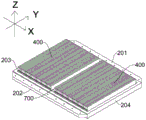
fig. 4 is a schematic diagram of an arrangement of a plurality of unit batteries in a battery pack case according to an embodiment of the present application;
FIG. 5 is a schematic perspective view of a side frame according to an embodiment of the present application;
FIG. 6 is a schematic perspective view of a side frame according to another embodiment of the present application;
FIG. 7 is a schematic perspective view of a side frame according to yet another embodiment of the present application;
FIG. 8 is an enlarged view of a portion of FIG. 7 at A;
FIG. 9 is a cut-away perspective view of a battery pack of an embodiment of the present application;
fig. 10 is a partial enlarged view at B in fig. 9;
fig. 11 is a cross-sectional view of a battery pack according to another embodiment of the present application, wherein the first and second rims are not shown;
fig. 12 is an exploded view of a battery pack according to an embodiment of the present application;
FIG. 13 is a perspective view of a side panel according to one embodiment of the present application;
FIG. 14 is a schematic perspective view of an end plate according to an embodiment of the present application;
fig. 15 is a schematic perspective view of a battery pack according to an embodiment of the present application, wherein the battery array includes a single layer;
fig. 16 is a schematic perspective view of a battery pack according to another embodiment of the present application, wherein the battery array includes a plurality of layers;
fig. 17 is a schematic perspective view of a battery pack according to still another embodiment of the present application, wherein a battery array includes a plurality of batteries distributed along a Y-direction;
fig. 18 is a schematic perspective view of a battery pack according to still another embodiment of the present application, wherein the battery array includes a plurality of cells distributed along the X direction;
fig. 19 is a schematic perspective view of a battery pack according to still another embodiment of the present application, wherein a battery array includes a plurality of batteries distributed along X and Y directions;
fig. 20 is a schematic perspective view of a battery pack according to yet another embodiment of the present application, wherein the battery array includes a single layer;
fig. 21 is a schematic perspective view of a battery pack according to yet another embodiment of the present application, wherein the battery array includes a single layer;
FIG. 22 is a schematic plan view of a liquid cooled plate according to one embodiment of the present application;
FIG. 23 is a schematic plan view of a liquid-cooled panel according to another embodiment of the present application;
FIG. 24 is a schematic plan view of a liquid cooled plate according to yet another embodiment of the present application;
FIG. 25 is a schematic perspective view of a vehicle mounted battery pack according to an embodiment of the present application;
FIG. 26 is a cross-sectional view of a cavity for mounting a battery pack on a vehicle according to one embodiment of the present application;
FIG. 27 is a schematic perspective view of a battery pack according to one embodiment of the present application secured to a vehicle;
FIG. 28 is an exploded view of one embodiment of the present application with a battery pack secured to a vehicle;
FIG. 29 is a schematic illustration of a vehicle according to an embodiment of the subject application;
fig. 30 is a schematic structural view of an energy storage device according to an embodiment of the present application.
Reference numerals:
the vehicle 1, the energy storage device 2,
the battery pack 10 is provided with a battery pack,
a single cell 100, an outgoing terminal 101, an explosion-proof valve 103,
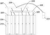
a battery pack case 200, a side frame 200a, a first frame 201, a second frame 202, a third frame 203, a fourth frame 204, a first end plate 207, an end plate body 207a, a first connecting plate 207b, a via hole 207c, a second end plate 208, a first side plate 209, a side plate body 209a, a second connecting plate 209b, a second side plate 210, a bottom plate 211, a panel 212, a supporting plate 213, a supporting surface 213a, a mounting surface 213b, a first connecting surface 215, a second connecting surface 216, a heat insulating layer 217, a heat conducting plate 218, a heat exchange plate 219, a sealing cover 220, an exhaust hole 221, an exhaust passage 222, a gas-liquid separator 223, a cooling liquid pipe 224, a cooling liquid inlet 225, a cooling liquid outlet 226, a liquid inlet manifold 227, a liquid outlet 228, a cooling liquid inlet 229, a cooling liquid outlet 230,
a first edge beam 301, a first support plate 301a, a first support surface 301b, a first mounting surface 301c, a second edge beam 302, a second support plate 302a, a second support surface 302b, a second mounting surface 302c,
the number of cells in the cell array 400,
the battery module 400a, the cross member 500, the side member 600,
the width direction beam 700, the length direction beam 800,
length L of the battery cell, thickness D of the battery cell, height H of the battery cell, distance L2 between the inner wall surface of the first frame and the inner wall surface of the second frame, width L3 of the battery pack case in the first direction, and length L4 of the battery pack case in the second direction.
Detailed Description
Reference will now be made in detail to embodiments of the present application, examples of which are illustrated in the accompanying drawings, wherein like or similar reference numerals refer to the same or similar elements or elements having the same or similar function throughout. The embodiments described below with reference to the drawings are exemplary only for the purpose of explaining the present application and are not to be construed as limiting the present application.
The battery pack 10 of the application can be used for passenger vehicles, commercial vehicles, special vehicles, ships, standby power supplies (dps and ups), electric bicycles, electric motorcycles, electric scooters and other devices which need to use the single battery 100 to provide electric energy for the vehicles, and the battery pack 10 of the application can be used as a power battery pack of a vehicle.
A battery pack 10 according to an embodiment of the present application is described below with reference to fig. 2 to 28.
In the embodiment of the present application, the front-rear direction is the longitudinal direction of the vehicle 1, i.e., the X direction, unless otherwise specified; the left-right direction is the lateral direction of the vehicle 1, i.e., the Y direction; the up-down direction is the vertical direction of the vehicle 1, i.e., the Z direction.
As shown in fig. 2 to 28, the battery pack 10 of the present application includes a battery pack case 200 and a plurality of unit batteries 100.
As shown in fig. 2, each of the unit batteries 100 has a battery case, a battery cell provided in the battery case, and an outgoing terminal 101 connected to the battery cell and extending out of the battery case. In the embodiment shown in fig. 2, the unit cell 100 has two lead-out terminals 101, and the two lead-out terminals 101 protrude from both end surfaces of the battery case, respectively. Of course, in other embodiments, a plurality of lead-out terminals 101 of the single battery 100 may also extend out of the same surface of the battery case, or more lead-out terminals 101 may be provided for each single battery 100.
In some embodiments of the present application, as shown in fig. 2, two lead-out terminals 101 of the unit battery 100 are respectively led out from both ends in the length direction of the unit battery 100. In other words, the length direction of the unit battery 100 may be a current direction inside the unit battery 100, that is, the current direction inside the unit battery 100 is the first direction. Thus, since the current direction is the same as the length direction of the unit battery 100, the effective heat dissipation area of the unit battery 100 is larger, and the heat dissipation efficiency is better.
The single battery cells 100 may have any suitable structure and shape, and in one embodiment provided herein, as shown in fig. 2, the single battery cells 100 are rectangular cells having a rectangular parallelepiped structure and have a length, a thickness and a height between the length and the thickness, each single battery cell 100 is placed on its side, the length direction of each single battery cell 100 is a first direction, the thickness direction is a second direction, and the height direction is a third direction, and two adjacent single battery cells 100 are arranged in a large-to-large manner.
Specifically, the unit cell 100 has a large side, a narrow side and an end surface, the long side of the large side has the length L, the short side has the height H, the long side of the narrow side has the length L, the short side has the thickness D, the long side of the end surface has the height H, and the short side has the thickness D, the unit cell 100 is placed on its side means that the two end surfaces of the unit cell 100 respectively face the first frame 201 and the second frame, and the large sides of the adjacent two unit cells 100 face each other, so that the unit cell 100 has a function of replacing a cross beam, and the effect is better, and the strength is higher.
In the related art, how to design the shape and size of the single battery 100 to have not only a proper battery capacity and a good heat dissipation effect is one of the problems to be solved in the battery technology field.
In one embodiment provided by the application, the ratio of the length L of the single battery 100 to the thickness D satisfies 23 ≤ L/D ≤ 208, under the ratio, the single battery 100 with longer length and thinner thickness can be obtained, thus, the proper resistance value, higher heat dissipation area and heat dissipation efficiency can be ensured under the condition that the length of the single battery 100 extends along the first direction, and the adaptability of various vehicle types is good.
In another embodiment provided herein, the ratio of the surface area S to the volume V of the unit cell 100 satisfies 0.1mm-1≤S/V≤0.35mm-1. Under this ratio, can be longer through above-mentioned length, the thin battery cell 100 of thickness realizes, also can realize through the adjustment of size, through the ratio of the superficial area S of control battery cell 100 and volume V, when can guarantee that battery cell 100 'S length extends along first direction, possesses sufficient heat radiating area to guarantee battery cell 100' S radiating effect.
In yet another embodiment provided herein, the ratio of the surface area S to the energy E of the cell 100 satisfies the S/E ≦ 1000mm2·Wh﹣1Preferably 250mm2·Wh﹣1≤S/E≤400mm2·Wh ﹣12. At this ratio, the single battery 100 having a long length and a thin thickness can still be obtained, and also, the ratio can be increased by the above-mentioned length. The single battery 100 having a small thickness may be realized by adjusting other dimensions. By controlling the ratio of the surface area S of the single battery 100 to the energy E, the surface area of the single battery 100 can meet the heat dissipation requirement while the single battery 100 has a certain energy E.
In some embodiments, in an embodiment provided by the present application, the single battery 100 may be a metal-casing prismatic battery, that is, the casing of the single battery 100 is made of a metal material, and the heat conductivity of the metal is better, so that the heat dissipation efficiency of the single battery 100 can be further improved, and the heat dissipation effect can be optimized. In another embodiment that this application provided, battery cell 100 can be laminate polymer battery, and laminate polymer battery means sheathes one deck polymer shell at liquid lithium ion battery, structurally adopts the plastic-aluminum membrane packing, and under the condition that takes place the potential safety hazard, laminate polymer battery can blow open, and can not explode to improve battery cell 100's security performance.
As shown in fig. 2, 4, 12, 17-19, a plurality of single batteries 100 are arranged in the battery pack case 200, and a plurality of single batteries 100 are arranged in the battery array 400 and then installed in the battery pack case 200, since a module frame is not needed, most of the space in the battery pack case 200 can be used for accommodating the single batteries 100 themselves, more single batteries 100 can be installed in the battery pack case 200 with the same volume, and the battery capacity of the battery pack 10 is large.
Because a module frame is not needed, the single batteries 100 can be arranged in the battery pack case 200 more closely, in the embodiments shown in fig. 2, fig. 4, fig. 12, and fig. 17-fig. 19, the module frame is not needed to be arranged between the plurality of single batteries 100, two adjacent single batteries 100 can be attached to each other by facing the side surface with the height of length, close stacking is convenient to realize by the arrangement mode with the facing large surface, and the overall rigidity of the battery array 400 formed by the plurality of single batteries 100 is large, so that the utilization rate of the installation space in the battery pack case 200 can be greatly improved, and the number of the single batteries 100 is increased.
The battery package 10 of this application is the battery package of no module frame, and a plurality of battery cell 100 direct mount have saved the module frame in battery package shell 200, have reduced component quantity and equipment process, and the cost is reduced, and the battery cell 100 quantity of installation increases in the battery package shell 200, has improved battery package 10's battery capacity, has improved duration.
In some embodiments of the present application, as shown in fig. 3, 9 and 12, the battery pack case 200 includes: a tray and a sealing lid 220.
The tray defines a battery receiving cavity having an open end, and a plurality of unit batteries 100 are arranged in the battery receiving cavity and connected to the tray.
The sealing cover 220 is mounted at the open end of the tray, and the sealing cover 220 seals the open end of the battery receiving cavity such that the unit batteries 100 are substantially enclosed in the battery pack case 200 to prevent the intrusion of impurities of water and dust. The sealing cover 220 and the tray can be connected through viscose; or the sealing cover 220 is connected with the tray through a threaded connecting piece; or the sealing cover 220 is connected with the tray through the adhesive and the threaded connector, so that the sealing cover 220 can be firmly connected with the tray through the threaded connector, and the sealing at each position can be realized through the adhesive.
The battery pack 10 of the present invention is not a small pack, but a large-volume battery pack 10, and the corresponding tray is a vehicle tray.
In the tray for the vehicle, the width of the vehicle body is large, such as 1.2m-2 m; longer length, such as between 2m and 5 m; the corresponding vehicle body width and the vehicle body length are different for different vehicle types. The tray is large in size requirement due to the large width and length of the vehicle body.
For the larger size of the tray, in the related art, as shown in fig. 1, the cross beam 500 and the longitudinal beam 600 must be disposed in the side frame 200a of the tray to provide sufficient supporting force and structural strength for the internal battery, and after the cross beam 500 and the longitudinal beam 600 are added to the vehicle tray, the weight and the internal space of the entire vehicle tray are occupied, so that the space that can be effectively utilized is lower inside the tray; meanwhile, due to the existence of the cross beam 500, in order to be installed in cooperation with the cross beam 500, a plurality of battery modules 400a must be arranged in the width and length directions inside the tray, the installation is complicated, and a large number of required installation structural members are required.
Because the cross beams and/or the longitudinal beams are arranged in the battery pack shell in the related art, and the cross beams and/or the longitudinal beams occupy a large amount of installation space for accommodating the single batteries in the battery pack shell, the volume utilization rate of the battery pack shell is low, generally, the volume utilization rate of the battery pack shell is about 40% or even lower, that is, only about 40% of the space in the battery pack shell in the related art can be used for installing the single batteries, so that the number of the single batteries which can be accommodated in the battery pack shell is limited, the capacity and the voltage of the whole battery pack are limited, and the cruising ability of the battery pack is poor.
However, in the present application, the unit cells 100 are directly mounted in the battery pack case 200, so that the use of cross beams and/or longitudinal beams in the battery pack case 200 is reduced, and even the cross beams and/or longitudinal beams may not be used in the battery pack case 200, so that the space occupied by the cross beams and/or longitudinal beams in the battery pack case 200 is reduced, the space utilization rate of the battery pack case 200 is improved, more unit cells 100 can be arranged in the battery pack case 200 as much as possible, and the capacity, voltage and endurance of the whole battery pack are improved. For example, in an electric vehicle, the design can improve the space utilization rate from about 40% to more than 60% or even higher, such as 80%.
In addition, since no cross beam and/or longitudinal beam is required to be arranged in the battery pack case 200, on one hand, the manufacturing process of the battery pack case 200 is simplified, the assembly complexity of the single batteries 100 is reduced, and the production cost is reduced, and on the other hand, the weight of the battery pack case 200 and the whole battery pack is reduced, and the light weight of the battery pack is realized. Particularly, when the battery pack is installed on the electric vehicle, the cruising ability of the electric vehicle can be improved, and the light weight of the electric vehicle is realized.
In some embodiments, the tray may be a separately produced tray for a vehicle for mounting the unit batteries 100, as shown in fig. 27 to 28, and after the unit batteries 100 are mounted on the tray and the open end of the tray is closed by the sealing cover 220 to form the battery pack 10, the tray may be mounted on the vehicle body by a fastener, for example, the tray may be provided with a lifting lug for lifting to the chassis of the vehicle 1.
In other embodiments, as shown in fig. 25-26, the tray may also be integrally formed with a chassis of the vehicle 1, the chassis has a first side beam 301 and a second side beam 302 oppositely disposed along the Y direction, the first side beam 301 and the second side beam 302 serve as a support for supporting the battery array 400, the first end of the battery cell 100 is supported by the first side beam 301, and the second end of the battery cell 100 is supported by the second side beam 302.
In a practical implementation, each of the first and second side members 301 and 302 extends downward to correspond to the first and second side frames 201 and 202 forming the tray, the first and second side members 301 and 302 have a bent (L-shaped) cross section, the first side member 301 has a first support plate 301a protruding toward the inner wall surface of the cell 100, the first support plate 301a has a first support surface 301b facing the sealing cover 220, the first support plate 301a has a first mounting surface 301c facing away from the sealing cover 220, the second side member 302 has a second support plate 302a protruding toward the inner wall surface of the cell 100, the second support plate 302a has a second support surface 302b facing the sealing cover 220, the second support plate 302a has a second mounting surface 302c facing away from the sealing cover 220, the first and second support surfaces 301b and 302b are used to support the cell 100, and the first and second mounting surfaces 301c and 302c are used to mount the bottom plate 211.
As shown in fig. 26, the first support plate 301a of the first side member 301 and the second support plate 302a of the second side member 302 are disposed at the same height in the Z direction so as to support the unit batteries 100 in a balanced manner.
As shown in fig. 26, the first support plate 301a of the first edge beam 301 and the second support plate 302a of the second edge beam 302 may extend only to a spaced position, and the bottom plate 211 needs to be erected below to close the lower end, so that the length of the frame relative to the waste material is short, and the weight of the whole vehicle can be reduced; of course, the first support plate 301a of the first edge beam 301 and the second support plate 302a of the second edge beam 302 may be extended to be connected to each other, so that a cavity with a closed lower end is formed, and the unit cells 100 may be effectively protected under.
In some embodiments of the present application, as shown in fig. 5-10, the tray comprises: a side frame 200a and a bottom plate 211, the bottom plate 211 being connected to the side frame 200a to define a battery receiving cavity, and the unit battery 100 being connected to the side frame 200 a.
In the related art, as shown in fig. 1, the batteries are all supported on the bottom plate, and the requirements on the rigidity and the strength of the bottom plate are high, more cross beams 500 and longitudinal beams 600 need to be arranged to enhance the supporting strength and the rigidity of the bottom plate, so that the limited space in the battery pack shell is further occupied, and if the cross beams 500 and the longitudinal beams 600 are removed, the tray cannot provide sufficient bearing force.
In the application, the single battery 100 is connected with the side frame 200a, the performance of the side frame 200a with high rigidity and strength is fully utilized, so that the bottom plate 211 does not need to play a main bearing role, the cross beam 500 and the longitudinal beam 600 in the tray can be removed, and the released space can be used for arranging more single batteries 100.
It should be noted that, as shown in fig. 3-10, the side frame 200a is generally made of a hollow profile, the hollow cavity of the side frame 200a is used to provide collision energy absorption, the plate ribs in the hollow cavity of the side frame 200a can enhance the strength of the side frame 200a, the outer side wall of the side frame 200a can be further provided with reinforcing ribs, and the strength and rigidity of the side frame 200a completely meet the requirements of installing the battery array 400.
In some embodiments, the unit cell 100 may be connected to the inner peripheral wall of the side frame 200a, or in the embodiment shown in fig. 10, the unit cell 100 is supported by the side frame 200a, which makes full use of the high rigidity and strength of the side frame 200 a.
As shown in fig. 3-12 and fig. 15-19, the side frame 200a includes a first frame 201, a second frame 202, a third frame 203, and a fourth frame 204, the first frame 201, the third frame 203, the second frame 202, and the fourth frame 204 are sequentially connected end to form a closed loop, the first frame 201 and the second frame 202 are disposed oppositely along a first direction, and the third frame 203 and the fourth frame 204 are disposed oppositely along a second direction.
The first frame 201, the second frame 202, the third frame 203 and the fourth frame 204 may be all in a long shape, the first frame 201 and the second frame 202 are spaced apart in parallel, the third frame 203 and the fourth frame 204 are spaced apart in parallel, and the side frame 200a may be a substantially rectangular frame.
In an actual implementation, after the battery pack 10 is mounted on the entire vehicle, the first direction may be the Y direction, and the second direction may be the X direction. Of course, for different vehicle models, the installation manner of the battery pack 10 may be adjusted such that the first direction corresponds to the X direction, the second direction corresponds to the Y direction, or other corresponding relationships are provided.
Inner wall surfaces of the first frame 201 and the second frame 202 facing the battery accommodating chamber each have a support surface 213a, and both ends of the unit battery 100 in the longitudinal direction thereof are supported by the support surfaces 213a of the first frame 201 and the second frame 202, respectively. The inner wall surface of the first frame 201 refers to the wall surface of the first frame 201 facing the second frame 202; the inner wall surface of the second frame 202 refers to a wall surface of the second frame 202 facing the first frame 201.
Each unit battery pack 10 includes a first end and a second end opposite to each other, and as shown in fig. 2, the first end of each unit battery 100 is supported by the first frame 201, and the second end of each unit battery 100 is supported by the second frame 202, at both ends in the longitudinal direction (Y direction in the drawing) of the unit battery 100 itself.
In other words, each unit cell 100 extends between the first frame 201 and the second frame 202, and the plurality of unit cells 100 are arranged along the length direction of the first frame 201 and the second frame 202, i.e., along the second direction.
Here, the first end and the second end of the single battery 100 are respectively supported on the first frame 201 and the second frame 202, and the single battery 100 may be directly supported by the first frame 201 and the second frame 202, i.e. respectively placed on the supporting surfaces 213a of the first frame 201 and the second frame 202, or may be further fixed on the supporting surfaces 213a of the first frame 201 and the second frame 202, such as being adhered to the supporting surfaces 213a of the first frame 201 and the second frame 202, and the specific fixing manner is described in detail below, and the application is not limited to a specific supporting and fixing manner.
Under the technical concept of the present application, in an embodiment, the distance between the first frame 201 and the second frame 202 matches the size of the single battery 100 along the first direction, where the matching refers to that the distance between the inner wall surfaces of the two frames can be matched to mount one single battery 100, and the matching may be various matching manners such as clearance fit, interference fit, fastening fit, and fixed fit, so as to achieve the purpose of the present application.
In some embodiments of the present application, a first end of each unit cell 100 may be directly or indirectly supported on the first frame 201, and a second end of each unit cell 100 may be directly or indirectly supported on the second frame 202. The direct meaning means that the first end of the single battery 100 is directly contacted and matched with the first frame 201 for supporting, and the second end of the single battery 100 is directly contacted and matched with the second frame 202; by indirect, it is meant that, for example, in some embodiments, a first end of the cell 100 is supported by the first end plate 207 in cooperation with the first frame 201, and a second end of the cell 100 is supported by the second end plate 208 in cooperation with the second frame 202.
It should be noted that the first frame 201 and the second frame 202 are disposed oppositely, and the first frame 201 and the second frame 202 may be parallel to each other, may also be disposed at an angle, and may be a straight line structure or a curved line structure. The single battery 100 may be perpendicular to the first frame 201 and/or the second frame 202, or disposed at an acute angle or an obtuse angle with respect to the first frame 201 and/or the second frame 202, for example, when the first frame 201 and the second frame 202 are parallel to each other, the first frame 201, the second frame 202, and the single battery 100 may form a rectangular, square or parallelogram, fan-shaped structure, etc.; when the first frame 201 and the second frame 202 are at an angle, the first frame 201, the second frame 202 and the single battery 100 may form a trapezoid, a triangle, or the like. The angular relationship between the first frame 201 and the second frame 202 and the angular relationship between the single battery 100 and the first frame 201 and the second frame 202 are not limited in the present application.
In addition, the above-mentioned "first end" and "second end" of the unit cell 100 are used to describe the orientation of the unit cell 100, and are not used to define and describe the specific structure of the unit cell 100, for example, the first end and the second end are not used to define and describe the positive electrode and the negative electrode of the unit cell 100, that is, in the present application, the end of the unit cell 100 supported by the first frame 201 is the first end, and the end of the unit cell 100 supported by the second frame 202 is the second end.
Note that the first end and the second end are not end faces, and in actual implementation, the end faces of the side faces of the unit cell 100, for example, the end portions of the narrow faces with length x thickness, are in supporting relation with the supporting faces 213a of the first frame 201 and the second frame 202.
In some embodiments, the single batteries 100 and the side frames 200a may be connected by a pre-connection structure to prevent the single batteries 100 without the module frame from shaking in the tray, and to facilitate the installation of a fixing structure at the rear. For example, both ends of the unit cell 100 may be adhered to the supporting surfaces 213a of the first and second frames 201 and 202 in a quick manner, and the assembly may be quickly performed by applying glue along the length direction (second direction) of the supporting surface 213a in a single time.
In some embodiments, the end portion (end portion in the longitudinal direction) of the unit cell 100 is provided with the lead-out terminal 101, and an insulating plate is interposed between the inner wall surfaces of the first frame 201 and the second frame 202 and the end surface of the unit cell 100, and is used for preventing the lead-out terminal 101 of the unit cell 100 from being conducted to the side frame 200 a.
As shown in fig. 5 to 7 and 10, the inner wall surface of the first frame 201 facing the battery accommodating chamber has a support plate 213 protruding inward, the inner wall surface of the second frame 202 facing the battery accommodating chamber has a support plate 213 protruding inward, a support surface 213a is provided on a surface (upper surface) of the support plate 213 facing the sealing cover 220, a surface (lower surface) of the support plate 213 facing away from the sealing cover 220 forms a mounting surface 213b, and the mounting surface 213b is used for mounting the bottom plate 211.
In practical implementation, as shown in fig. 5-7, the first frame 201, the second frame 202, the third frame 203, and the fourth frame 204 jointly extend inward to form a supporting plate 213 with the same height, so that the supporting plate 213 is equivalent to a closed loop, and the lower surface of the supporting plate 213 forms a mounting surface 213b with a ring shape, so as to facilitate the installation of the bottom plate 211, and the bottom plate 211 and the mounting surface 213b can be connected by bonding.
As shown in fig. 10, the inner ring of the side frame 200a at the end facing away from the sealing cover 220 has an annular sinking groove, the bottom wall of the sinking groove forms a mounting surface 213b, and the bottom plate 211 is mounted in the sinking groove. In other words, the lower surface of the support plate 213 is recessed upward with respect to the lower surface of the side frame 200a, so that the bottom plate 211 can be mounted using the inner space of the side frame 200a, for example, in the embodiment shown in fig. 10, the lower surface of the bottom plate 211 is substantially flush with the lower surface of the side frame 200a, so that the height of the entire battery pack 10 is small.
The unit cell 100 is supported by the side frame 200a, and the unit cell 100 is spaced apart from the bottom plate 211. The bottom plate 211 does not need to bear the weight of the unit battery 100, so that the bottom plate 211 can be thinned. An insulating layer 217 is arranged between the unit batteries 100 arranged at intervals and the bottom plate 211. As shown in fig. 10, the supporting plate 213, the single battery 100 and the bottom plate 211 jointly define a heat preservation cavity for accommodating the heat preservation layer 217, the thickness of the heat preservation layer 217 may be substantially equal to the thickness (Z direction) of the supporting plate 213, the heat preservation layer 217 is used for isolating the single battery 100 from external heat transfer, so as to realize the heat preservation function of the single battery 100 and avoid the phenomenon of thermal interference between the external environment outside the accommodating device and the single battery 100 inside the accommodating device. Alternatively, the insulating layer 217 may be made of a material having a heat insulating and preserving function, for example, made of insulating cotton.
As shown in fig. 5 to 7 and 10, inner wall surfaces of the first and second rims 201 and 202 facing the battery receiving cavity each have a first coupling surface 215, a distance from the first coupling surface 215 to the sealing cover 220 is smaller than a distance from the supporting surface 213a to the sealing cover 220, and the unit battery 100 is coupled to the first coupling surface 215. That is, the single battery 100 is not supported by the side frame 200a only through the supporting surface 213a, and the supporting surface 213a and the first connecting surface 215 are provided to reduce the pressure of the single battery 100 that the side frame 200a receives at a single location, distribute the pressure throughout, and prevent the side frame 200a from being partially cracked.
The first connection surface 215 is located radially outward with respect to the support surface 213a so as not to interfere with the loading of the unit cells 100 into the tray from the upper open end.
In a practical implementation, as shown in fig. 5-7, an inner wall surface of the first frame 201 or the second frame 202 facing the battery receiving cavity has at least two steps, wherein two step surfaces form a first connecting surface 215 and a supporting surface 213a, respectively, and the first connecting surface 215 and the supporting surface 213a are connected by a vertical inner wall surface. The multi-step structure is convenient to form, and can enhance the structural strength of the side frame 200a, and the assembly of the unit battery 100 is realized in a limited space. An insulating plate may be provided between the end surface of the unit battery 100 and the vertical inner wall surface between the first connection surface 215 and the support surface 213 a.
As shown in fig. 10 and 12, the battery pack 10 further includes: and end plates, which are provided at both ends of the unit cell 100 in the length direction thereof, and through which the unit cell 100 is connected to the first connection surface 215. The insulating plate may be integrally provided with the end plate.
As shown in fig. 14, the end plate includes an end plate body 207a and a first connection plate 207b, the end plate body 207a is disposed opposite to the end surface of the unit cell 100, the first connection plate 207b is connected to the end plate body 207a and protrudes toward the side frame 200a, the first connection plate 207b is connected to the first connection surface 215, and the first connection plate 207b and the end plate body 207a may be formed in a bent shape, such as L shape, of course, for such a multi-layered battery pack 10 as shown in fig. 16, the first connection plate 207b and the end plate body 207a may be formed in a T shape.
For convenience of description, the end plate provided at the first end of the unit cell 100 is defined as a first end plate 207, the end plate provided at the second end of the unit cell 100 is defined as a second end plate 208, and the first end plate 207 and the second end plate 208 may have the same structure. A first end of the single battery 100 is supported on the first frame 201 through a first end plate 207, and a second end of the single battery 100 is supported on the second frame 202 through a second end plate 208; the first end plate 207, the second end plate 208 and the unit cells 100 constitute a battery array 400.
In this way, the end plate body 207a of the first end plate 207 is sandwiched between the first end face of the unit cell 100 and the first frame 201, and the first connection plate 207b of the first end plate 207 is supported by the first connection face 215 of the first frame 201 and is connected to the first connection face 215 of the first frame 201; the end plate body of the second end plate 208 is sandwiched between the second end face of the unit cell 100 and the second frame 202, and the first connection plate of the second end plate 208 is supported by the first connection surface 215 of the second frame 202 and connected to the first connection surface 215 of the second frame 202.
In an actual implementation, as shown in fig. 14, the first connection plate 207b is provided with a plurality of mounting holes, the plurality of mounting holes are distributed at intervals along the second direction, the position of the first connection plate 207b where the mounting holes are provided can be widened compared with other regions, and the first connection plate 207b can be connected to the first connection surface 215 by a screw connection.
For a single cell array 400, there may be one first end plate 207 and one second end plate 208; of course, a plurality of first end plates 207 or second end plates 208 may be provided.
As shown in fig. 8 and 10, at least one of both end faces of the unit cell 100 is provided with the explosion-proof valve 103, the end plate body 207a of at least one of the two end plates (the first end plate 207 and the second end plate 208) is provided with a through hole 207c corresponding to the explosion-proof valve 103, and at least one of the first frame 201 and the second frame 202 is provided with a gas discharge hole 221 corresponding to the through hole 207c and a gas discharge channel 222 communicating with the gas discharge hole 221.
In one embodiment, the single battery 100 is provided with an explosion-proof valve 103 towards a first end of the first frame 201, the first frame 201 is internally provided with an exhaust channel 222, the exhaust channel 222 can be naturally formed inside the first frame 201 in a cavity type, a through hole 207c is formed in the first end plate 207 at a position corresponding to the explosion-proof valve 103 of each single battery 100, an exhaust hole 221 is formed in the first frame 201 at a position corresponding to the explosion-proof valve 103 of each single battery 100, the exhaust hole 221 is communicated with the exhaust channel 222, and the battery pack case 200 is provided with an exhaust port communicated with the exhaust channel 222; and/or the second end of the single battery 100 facing the second frame 202 is provided with an explosion-proof valve 103, the inside of the second frame 202 is provided with an exhaust channel 222, the position of the second end plate 208 corresponding to the explosion-proof valve 103 of each single battery 100 is provided with a via hole 207c, the position of the second frame 202 corresponding to the explosion-proof valve 103 of each single battery 100 is provided with an exhaust hole 221, the exhaust hole 221 is communicated with the exhaust channel 222, and the battery pack case 200 is provided with an exhaust port communicated with the exhaust channel 222. In other embodiments, the explosion-proof valves 103 are disposed at both ends of the single battery 100, correspondingly, the first end plate 207 and the second end plate 208 are disposed with the through holes 207c, and the first frame 201 and the second frame 202 are disposed with the exhaust holes 221 and the exhaust channels 222.
In the related art, if the gas pressure inside the single battery 100 increases to a certain degree during the use of the single battery 100, the explosion-proof valve 103 is opened, and the flame, smoke, or gas inside the single battery 100 is discharged through the explosion-proof valve 103, and the flame, smoke, or gas may be accumulated inside the battery pack 10, and if the flame, smoke, or gas cannot be discharged in time, secondary damage may be caused to the single battery 100. However, in the present application, since the vent hole 221 corresponding to the explosion-proof valve 103 of the battery cell 100 is disposed on the first frame 201 and/or the second frame 202, and the vent channel 222 is disposed inside the first frame 201 and/or the second frame 202, when the internal pressure of the battery cell 100 increases, the explosion-proof valve 103 thereof is opened, and the flame, smoke, or gas inside thereof will directly enter the vent channel 222 inside the first frame 201 and/or the second frame 202 through the air inlet, and be vented out of the first frame 201 and/or the second frame 202 through the vent hole 221, for example, to the atmosphere through the air outlet, so that the flame, smoke, or gas will not be gathered inside the accommodating device, thereby avoiding secondary damage to the battery cell 100 caused by the flame, smoke, or gas.
As shown in fig. 3, 12 and 15, the first connecting surface 215 and the sealing cover 220 define a management accommodating cavity therebetween for accommodating the battery management component and the power distribution component. In actual implementation, the first connecting plate 207b is spaced apart from the sealing cover 220, and the management accommodating cavity can be defined by the first connecting plate 207b, the side frame 200a and the sealing cover 220, so that a circle of management accommodating cavity is formed at the periphery of the battery array 400, and the management accommodating cavity can be used for installing battery management components and power distribution components, so that installation space specially designed for the battery management components and the power distribution components is not needed, gaps after the battery array 400 is installed are fully utilized, and the maximization of the battery density is achieved.
In some embodiments, as shown in fig. 3, the third frame 203 applies a force to the unit cell 100 adjacent to the third frame 203 toward the fourth frame 204, and the fourth frame 204 applies a force to the unit cell 100 adjacent to the fourth frame 204 toward the third frame 203, so that the plurality of unit cells 100 can be closely arranged between the third frame 203 and the fourth frame 204 along the second direction, and the plurality of unit cells 100 can be attached to each other. In addition, the third frame 203 and the fourth frame 204 can limit the plurality of unit batteries 100 in the second direction, and particularly, when the unit batteries 100 are slightly expanded, the unit batteries 100 can be buffered and an inward pressure can be provided, so that the excessive expansion and deformation of the unit batteries 100 can be prevented. Particularly, when the unit cell 100 is provided with the explosion-proof valve 103 and the Current Interrupt Device (CID) device, the expansion of the unit cell 100 may be effectively restricted by the third frame 203 and the fourth frame 204, so that when the unit cell 100 fails and expands, the inside thereof may have sufficient air pressure to burst the explosion-proof valve 103 or the flip piece inside the Current Interrupt Device (CID) device, thereby short-circuiting the unit cell 100, ensuring the safety of the unit cell 100, and preventing the unit cell 100 from exploding.
In some embodiments, at least one of the elastic clamps between the third frame 203 and the unit cell 100 adjacent to the third frame 203 and between the fourth frame 204 and the unit cell 100 adjacent to the fourth frame 204 is provided with an elastic device.
A first elastic means may be disposed between the third rim 203 and the unit cell 100 adjacent to the third rim 203, and/or a second elastic means may be disposed between the fourth rim 204 and the unit cell 100 adjacent to the fourth rim 204. The first elastic means may be installed on the third frame 203, the second elastic means may be installed on the fourth frame 204, and the plurality of unit cells 100 are closely arranged by the first elastic means and the second elastic means, so that the number of unit cells 100 arranged between the third frame 203 and the fourth frame 204 may be adjusted by changing the installation distances between the first elastic means and the second elastic means and the third frame 203 and the fourth frame 204 without changing the distance between the third frame 203 and the fourth frame 204.
In some embodiments, as shown in fig. 12, the battery pack 10 further includes: side plates are arranged between the third frame 203 and the unit cell 100 adjacent to the third frame 203 and between the fourth frame 204 and the unit cell 100 adjacent to the fourth frame 204. The resilient means may be integrally provided with the side plate, which may be made of rubber.
As shown in fig. 13, the side plate includes a side plate body 209a and a second connection plate 209b, the side plate body 209a is disposed opposite to a side surface of the unit cell 100, the second connection plate 209b is connected to the side plate body 209a and protrudes toward the third frame 203 or the fourth frame 204, the third frame 203 and the fourth frame 204 are provided with a second connection surface 216 facing the sealing cover 220, and the second connection plate 209b is connected to the second connection surface 216. the second connection plate 209b and the side plate body 209a may be formed in a bent shape, such as L shape or T shape.
For convenience of description, a side plate disposed between the unit battery 100 and the third frame 203 is defined as a first side plate 209, a side plate disposed at a second end of the unit battery 100 is defined as a second side plate 210, and the first side plate 209 and the second side plate 210 may have the same structure. The first end plate 207, the second end plate 208, the first side plate 209, the second side plate 210 and the unit batteries 100 constitute a battery array 400. The plurality of unit cells 100 are all clamped at the periphery by end plates or side plates, so that the battery array 400 is substantially formed as a whole.
In this way, the side plate body 209a of the first side plate 209 is sandwiched between the side surface of the unit battery 100 and the third frame 203, and the second connecting plate 209b of the first side plate 209 is supported by the second connecting surface 216 of the third frame 203 and is connected to the second connecting surface 216 of the third frame 203; the side plate body of the second side plate 210 is clamped between the side surface of the single battery 100 and the fourth frame 204, and the second connection plate of the second side plate 210 is supported on the second connection surface 216 of the fourth frame 204 and connected to the second connection surface 216 of the fourth frame 204.
As shown in fig. 12, the two surfaces of the unit cell 100 in the third direction may be provided with panels 212, the upper ends of the end plates and the upper ends of the side plates are connected to the upper panel 212, the lower ends of the end plates and the lower ends of the side plates are connected to the lower panel 212, and the first end plate 207, the second end plate 208, the first side plate 209, the second side plate 210, the panel 212 and the unit cell 100 constitute a cell array 400 such that six sides of the unit cell 100 are all clamped.
In one embodiment, as shown in fig. 3, a plurality of unit batteries 100 may be directly mounted in the battery pack case 200, and first and second ends of the unit batteries 100 may be supported on the first and second rims 201 and 202, respectively.
In another embodiment, as shown in fig. 15-19, a plurality of single batteries 100 may be assembled into at least one battery array 400, and then the battery array 400 is mounted in the battery pack case 200. Based on the technical idea of the present application, the technical effects of the present disclosure can also be achieved by the external structure of the battery array 400 and the matching relationship between the first frame 201 and the second frame 202.
In some embodiments, as shown in fig. 12, the battery pack 10 includes: the battery pack comprises a panel 212, end plates, side plates, a plurality of single batteries 100 and a battery pack shell 200, wherein the single batteries 100 are arranged side by side, the arrangement mode of the single batteries 100 can refer to the description of the embodiment, the upper surface and the lower surface of each single battery 100 are connected with the panel 212, the end plates are arranged on two end surfaces of each single battery 100, and the side plates are arranged on the outer side surfaces of the two outermost single batteries 100; the end plates and the side plates are connected to the two panels 212, the inner wall surface of the side frame 200a of the battery pack case 200 facing the battery receiving cavity has a supporting surface 213a and connecting surfaces (a first connecting surface 215 and a second connecting surface 216), the two ends of the unit battery 100 are supported by the supporting surface 213a, and the end plates and the side plates are connected to the connecting surfaces.
When the plurality of elongated single batteries 100 are assembled to the battery pack case 200, the battery array 400 with a stable structure is not easy to form, and the panel 212, the end plate and the side plate are pressed inwards from six surfaces, so that the integrity of the battery array 400 is stable, and the assembly is convenient.
In some embodiments, a panel 212 is disposed under at least a portion of the single batteries 100, the panel 212 is connected to the first end plate 207, and the panel 212 is connected to the second end plate 208; the panel 212, the first end plate 207, the second end plate 208 and at least a portion of the battery cells 100 form a battery array 400. In other words, at least a part of the plurality of unit batteries 100 is provided with the panel 212, the panel 212 is connected with the first end plate 207, and the panel 212 is connected with the second end plate 208; the panel 212, the first end plate 207, the second end plate 208 and at least a portion of the plurality of unit batteries 100 form a battery array 400. In other words, the panel 212 may be one, the first end plate 207 and the second end plate 208 are connected to the panel 212, the first end plate 207, the second end plate 208, and the panel 212 form a receiving space for receiving the plurality of unit batteries 100, and when the battery pack is mounted, the plurality of unit batteries 100 are disposed in the receiving space, and then the first end plate 207 and the second end plate 208 are supported on the first frame 201 and the second frame 202. The face plate 212 may be plural so as to constitute a plurality of battery arrays 400 with the plurality of first end plates 207 and second end plates 208, and the plurality of battery arrays 400 are mounted in the battery pack case 200.
In some embodiments, a panel 212 is disposed above at least a portion of the unit cells 100, the panel 212 is connected to the first end plate 207, and the panel 212 is connected to the second end plate 208; the upper panel 212, the lower panel 212, the first end plate 207, the second end plate 208 and at least a portion of the single batteries 100 form a battery array 400. In other words, the panel 212 is disposed above at least a portion of the plurality of unit batteries 100, the panel 212 is connected to the first end plate 207, and the panel 212 is connected to the second end plate 208; the upper panel 212, the lower panel 212, the first end plate 207, the second end plate 208 and at least a portion of the plurality of unit batteries 100 form a battery array 400. In other words, the panel 212 is located on the top of the first end plate 207 and the second end plate 208, the panel 212 is located on the bottom of the first end plate 207 and the second end plate 208, and the single battery 100 is located between the panel 212 and the panel 212, so that the panel 212 and the panel 212 can prevent the single battery 100 from moving up and down, and the stability of the single battery 100 is increased.
In some embodiments, the battery pack case 200 has a third frame 203 and a fourth frame 204 disposed opposite to each other along a second direction different from the first direction, a first side plate 209 is disposed on a side of the unit battery 100 adjacent to the third frame 203 facing the third frame 203, a second side plate 210 is disposed on a side of the unit battery 100 adjacent to the fourth frame 204 facing the fourth frame 204, and the first end plate 207, the second end plate 208, the first side plate 209, the second side plate 210, the upper panel 212, the lower panel 212, and at least a portion of the plurality of unit batteries 100 form the battery array 400. The battery array 400 may be one or a plurality of, the first end plate 207, the second end plate 208, the first side plate 209, and the second side plate 210 may be disposed around the panel 212 and the panel 212, the first end plate 207 is fixed on the first frame 201, the second end plate 208 is fixed on the second frame 202, the first side plate 209 is fixed on the third frame 203, the second side plate 210 is fixed on the fourth frame 204, and the first end plate 207, the second end plate 208, the first side plate 209, the second side plate 210, the upper panel 212, and the lower panel 212 together define a closed accommodating space for accommodating the plurality of unit batteries 100, so that, when the single battery 100 fails and fires, the first end plate 207, the second end plate 208, the first side plate 209, the second side plate 210, the panel 212 and the panel 212 can control the failure of the single battery 100 within a certain range, and prevent the explosion of the single battery 100 from affecting surrounding components. Alternatively, the first side plate 209 may be the above-mentioned first elastic buffer plate, and the second side plate 210 may be the above-mentioned second elastic buffer plate, so that the first side plate 209 and the second side plate 210 have a function of limiting the expansion and deformation of the plurality of unit batteries 100, thereby ensuring the activation of the explosion-proof valve 103 and/or the Current Interrupt Device (CID).
In another embodiment, a panel 212 is disposed under at least some of the single batteries 100 in the plurality of single batteries 100, and at least some of the single batteries 100 are supported on the first frame 201 and the second frame 202 by the panel 212; the panel 212 and at least a portion of the battery cells 100 form a battery array 400. In other words, a panel 212 is disposed under at least a portion of the plurality of unit batteries 100, and each unit battery 100 is supported on the first frame 201 and the second frame 202 by the panel 212; the panel 212 and at least a part of the plurality of single batteries 100 form the battery array 400, and in this embodiment, the plurality of single batteries 100 are supported on the first frame 201 and the second frame 202 through the panel 212, so that the structure of the battery array 400 is simplified, and the light weight of the battery pack 10 is facilitated.
In the related art, since the unit battery 100 has a small size and a short length, the two opposite ends of the unit battery 100 cannot be matched with the two oppositely-arranged side beams in the battery pack case 200, and therefore, a cross beam and/or a longitudinal beam (as shown in the figure) needs to be arranged in the battery pack case 200, thereby facilitating the assembly of the unit battery 100. When the single battery 100 is mounted in the battery pack case 200 through the battery array 400, a plurality of single batteries 100 may exist along the first direction of the battery pack case 200, that is, the single battery 100 does not extend between two oppositely disposed side beams (the first side frame 201 and the second side frame 202, or the first side wall and the second side wall), but extends between two oppositely disposed cross beams or longitudinal beams, and the battery array 400 is fixed with the adjacent cross beams and/or longitudinal beams through fasteners.
In the present application, as shown in fig. 2, the length of the single battery 100 is L, the height thereof is H, and the thickness thereof is D, wherein 4 ≦ L/H ≦ 21, preferably 4 ≦ L/H ≦ 20, 23 ≦ L/D ≦ 208, preferably 23 ≦ L/D ≦ 200, that is, the size of the single battery 100 in the length direction is much larger than the size in the height direction and the thickness direction, and the elongated single battery 100 may extend from the first frame 201 to the second frame 202.
In a practical implementation, when the battery pack 10 is used as a battery pack 10 for supplying electric power used on a vehicle 1, the length direction of the unit battery 100 may be made the width direction of the vehicle 1, i.e., the left-right direction of the vehicle 1, and in some embodiments, the length L of the unit battery 100 satisfies 600mm ≦ L ≦ 2500mm, preferably 600mm ≦ L ≦ 1000mm, so that the length of the unit battery 100 can be adapted to the width of the vehicle 1.
In the embodiments shown in fig. 2, 4, 12, 17-19, two adjacent single batteries 100 may be attached with their side surfaces facing each other at a height, and the volume of the single battery 100 is V, and the height is H, which satisfy: 0.0001mm-2≤H/V≤0.00015mm-2。
It can be understood that, while V is constant, H/V is smaller and L × D is larger, in the above embodiment, the single battery 100 mainly depends on the length × thickness surface for heat dissipation, and the value L × D is increased, so that the heat dissipation effect of the single battery 100 can be enhanced, and heat accumulation can be prevented.
In some embodiments, the length direction of the single batteries 100 is perpendicular to the first frame 201 and the second frame 202, and the arrangement of the battery array 400 formed by a plurality of single batteries 100 in the tray is various, and several embodiments are described below.
In the embodiment shown in fig. 3 and 12, the distance between the first end and the second end of the battery cell 100 is L, the distance between the inner wall surface of the first frame 201 and the inner wall surface of the second frame 202 is L2, wherein the ratio of L to L2 satisfies L/L2 ≧ 50%. in other words, only one battery cell 100 is disposed between the first frame 201 and the second frame 202 along the first direction, and by so disposing the relationship of the distance between the battery cell 100 and the two frames in the first direction, the purpose of serving as a beam by the battery cell 100 can be achieved.
In some embodiments, the ratio of L to L2 may satisfy 80% ≦ L/L2 ≦ 97%, so that the first end and the second end of the battery cell 100 are as close to the first frame 201 and the second frame 202 as possible, and even abut against the first frame 201 and the second frame 202, so as to implement the force dispersion and conduction through the structure of the battery cell 100 itself, ensure that the battery cell 100 can be used as a beam for enhancing the structural strength of the battery pack case 200, and ensure that the battery pack case 200 has sufficient strength to resist the deformation of external force.
In the embodiment shown in fig. 3 and 12, a battery array 400 is disposed in the entire tray, so that the single batteries 100 can be densely stacked to the maximum extent.
In the embodiment shown in fig. 15 and 18, the entire tray is provided with at least two battery arrays 400 distributed in the second direction, with a certain gap between the adjacent battery arrays 400. Such as the embodiment shown in fig. 15, the battery pack 10 includes three battery arrays 400 arranged in the second direction, such as the embodiment shown in fig. 18, the battery pack 10 includes two battery arrays 400 arranged in the second direction.
It is understood that when the size of the battery pack 10 in the second direction is too large, assembly may be facilitated by providing a plurality of battery arrays 400, and accumulation of errors in the second direction during assembly may be reduced, leaving a certain expansion space in the second direction.
In other possible embodiments, under the concept of the present application, two or more unit batteries 100 may be provided in the first direction, and at least the space of the battery pack case 200 may be fully utilized.
As shown in fig. 17, the entire tray is provided with at least two battery arrays 400 distributed in the first direction, with a certain gap left between the adjacent battery arrays 400. It is understood that when the size of the battery pack 10 in the first direction is too large, assembly may be facilitated by providing a plurality of battery arrays 400, a certain expansion space may be left in the first direction, the length of the unit battery 100 may be shortened, and manufacturing of the unit battery 100 may be facilitated.
As shown in fig. 19, the entire tray is provided with at least two battery arrays 400 distributed in a first direction, and includes at least two battery arrays 400 distributed in a second direction. In the embodiment shown in fig. 19, the battery pack 10 includes 4 battery arrays 400 of 2 × 2, so that the length of each battery cell can be designed to be relatively short, the manufacturing of the battery cell 100 is facilitated, the accumulation of errors in the second direction during assembly is reduced, and a certain expansion space is left in the first direction and the second direction.
In the embodiment shown in fig. 16, the battery pack 10 is arranged with at least two layers of the plurality of unit batteries 100 in the vertical direction (Z direction). In other words, the plurality of unit batteries 100 are arranged in a plurality of layers stacked in the third direction (the third direction is perpendicular to the first direction and perpendicular to the second direction), the plurality of unit batteries 100 in each layer are located between the first frame 201 and the second frame 202, and the number of layers of the unit batteries 100 may be set according to the size of the battery pack case 200. In this way, a plurality of single batteries 100 can be arranged in the limited space of the battery pack case 200 as much as possible, thereby further improving the volume utilization rate of the battery pack case 200 and improving the capacity, voltage and endurance of the battery pack 10. Thus, when the whole vehicle has a sufficiently high space in the third direction, more single batteries 100 can be arranged, and the arrangement mode can shorten the size of the single batteries 100 in the height direction, so that the heat dissipation of the single batteries 100 is facilitated.
In the above embodiment, the single batteries 100 stacked in the third direction may be the single batteries 100 with both ends engaged with the first frame 201 and the second frame 202, or may be the single batteries 100 directly placed on top of the next layer of single batteries 100 without being supported or connected with the first frame 201 and the second frame 202.
In one embodiment provided herein, the first direction may be perpendicular to the second direction, the first direction being a length direction of each unit battery 100, and the second direction being a length direction of the first frame 201 and the second frame 202, i.e., a thickness direction of each unit battery 100. That is, the first frame 201 and the second frame 202 are perpendicular to the unit batteries 100, and both ends of each unit battery 100 in the length direction are supported on the first frame 201 and the second frame 202. Like this, when first frame 201 and/or second frame 202 received external force and assault, a plurality of battery cells 100 can carry out the conduction and the dispersion of power to better play additional strengthening's effect, improve the ability that battery package shell 200 resisted external force deformation. In this embodiment, as shown in fig. 3, 5, 6, 7, 15-19, the first frame 201 and the second frame 202 are linear structures, and the second direction is a linear direction, but in some possible embodiments, the first frame 201 and the second frame 202 may be curved structures, in which case the first direction may be a circumferential direction, and the corresponding second direction may be a radial direction.
In some embodiments of the present application, the battery pack 10 further includes: and a heat exchange plate 219, the heat exchange plate 219 being mounted on an upper surface of the unit battery 100.
For the embodiment in which the battery array 400 includes the heat exchange plate 219, as shown in fig. 11, a heat conduction plate 218 may be disposed between the heat exchange plate 219 and the single battery 100 to facilitate heat dissipation of the single battery and ensure that a temperature difference between the plurality of single batteries 100 is not too large. The thermally conductive plate 218 may be made of a material having good thermal conductivity, for example, the thermally conductive plate 218 may be made of a material having high thermal conductivity such as copper or aluminum.
In one embodiment, as shown in fig. 12, for an embodiment in which the battery array 400 includes the panel 212, the heat exchange plate 219 may be integrated with the upper panel 212, the heat exchange plate 219 may be liquid-cooled, the upper panel 212 is provided with a cooling channel inside, and a cooling liquid is provided inside the cooling channel, so that the temperature of the unit battery 100 is reduced by the cooling liquid, and the unit battery 100 can be at a suitable operating temperature. Since the heat-conducting plate 218 is disposed between the heat-exchanging plate 219 and the single battery 100, when the single battery 100 is cooled by the cooling liquid, the temperature difference between the heat-exchanging plate 219 and each position can be equalized by the heat-conducting plate 218, so that the temperature difference between the plurality of single batteries 100 is controlled within 1 ℃.
In order to improve the cooling effect of the heat exchange plate 219, as shown in fig. 17 to 19, a gas-liquid separator 223 may be disposed upstream of the heat exchange plate 219, and since the coolant in the heat exchange plate 219 may come from other thermal management circuits of the vehicle, and the coolant may be a coolant in which a gas state and a liquid state are mixed, after the gas-liquid mixed coolant is subjected to gas-liquid separation by the gas-liquid separator 223, the pure liquid-phase coolant can be ensured to enter the heat exchange plate 219 to cool the single battery 100, and the cooling effect is ensured.
The heat exchanger plates 219 may have any suitable configuration. In one embodiment, as shown in fig. 22, the heat exchange plate 219 may have a plurality of coolant pipes 224 therein, each coolant pipe 224 is formed in a U-shaped structure to have a coolant inlet 225 and a coolant outlet 226 located on the same side, the coolant inlets 225 and the coolant outlets 226 of the plurality of coolant pipes 224 are sequentially spaced along the arrangement direction of the plurality of coolant pipes 224, the battery pack further includes a liquid inlet manifold 227 and a liquid outlet manifold 228, each coolant inlet 225 is communicated with the liquid inlet manifold 227, and each coolant outlet 226 is communicated with the liquid outlet manifold 228.
In another embodiment, as shown in fig. 23 and 24, a plurality of coolant pipes 224 are provided in the heat exchange plate 219, the plurality of coolant pipes 224 are straight pipes and are arranged in parallel and spaced apart from each other, both ends of each coolant pipe 224 are respectively provided with a coolant inlet 225 and a coolant outlet 226 which are oppositely arranged, the coolant inlets 225 and the coolant outlets 226 of the plurality of coolant pipes 224 are sequentially arranged in spaced apart manner along the arrangement direction of the plurality of coolant pipes 224, the battery pack further comprises a liquid inlet manifold 227 and a liquid outlet manifold 228, each coolant inlet 225 is communicated with the liquid inlet manifold 227, and each coolant outlet 226 is communicated with the liquid outlet manifold 228. As shown in fig. 23 and fig. 24, a coolant inlet 229 is disposed on the inlet manifold 227, a coolant outlet 230 is disposed on the outlet manifold 228, and the coolant inlet 229 and the coolant outlet 230 are disposed on the same side or opposite sides of the heat exchange plates 219.
In another embodiment provided by the present disclosure, the panel 212 is a direct cooling plate having a cooling structure therein, the direct cooling plate is provided with a cooling medium therein, the cooling medium can be a cooling medium that is cooled by a vehicle air conditioning system, and the low-temperature cooling medium can effectively absorb heat of the battery cell 100, so that the temperature of the battery cell 100 is always maintained at a suitable temperature value. Wherein the piping in the direct cooling plates and the above-mentioned heat exchanger plates 219 may be the same or different.
As described below by comparative example 1 and examples 1 to 3, comparative example 2 and examples 4 to 5, and comparative example 3 and examples 6 to 7, the battery pack 10 according to the example of the present application is improved in energy density and the like by designing the arrangement, the dimensional parameters and the like of the unit cells 100.
Comparative example 1
In the related art battery pack 10, as shown in fig. 1, two cross members 500 and one longitudinal member 600 are provided in a battery pack case 200, and the two cross members 500 and the one longitudinal member 600 divide a unit cell 100 into six battery modules 400, each battery module 400 having a side member and an end member.
The ratio of the sum of the volumes of the unit batteries 100 of the battery pack 10 to the volume of the battery pack 10 is 54.76% (i.e., the space utilization rate is 54.76%), and the energy density of the battery pack 10 is 251 Wh/L.
Example 1
According to the battery pack 10 of the embodiment of the present application, as shown in fig. 19, the length direction of the unit batteries 100 is arranged along the width direction of the battery pack 10, the plurality of unit batteries 100 are arranged along the length direction of the battery pack 10, and the battery pack case 200 accommodates two unit batteries 100 in the width direction of the battery pack 10. A width direction beam 700 and a length direction beam 800 are arranged in the battery pack case 200, the width direction beam 700 extends along the width direction of the battery pack 10, the plurality of single batteries 100 are arranged along the length direction of the battery pack 10 to form the battery array 400, and the width direction beam 700 divides the battery array 400 into two parts along the length direction of the battery pack 10. Furthermore, two rows of battery arrays 400 are arranged in the width direction of the battery pack 10 in the plurality of unit batteries 100, and the length direction cross beam 800 is located between two adjacent rows of battery arrays 400. The first frame 201 and the second frame 202 of the battery pack case 200 located at both sides of the battery pack 10 in the width direction provide support for the unit batteries 100, and the third frame 203 and the fourth frame 204 of the battery pack case 200 located at both ends of the battery pack 10 in the length direction provide inward pressing force for the adjacent unit batteries 100. The battery pack case 200 contains two layers of the battery array 400 therein in the height direction of the battery pack 10. The battery array 400 (also understood as a battery module) of the battery pack 10 is not provided with end beams and side beams.
In the present embodiment, the ratio of the sum of the volumes of the unit batteries 100 of the battery pack 10 to the volume of the battery pack 10 is 57.39% (i.e., the space utilization ratio is 57.39%), and the energy density of the battery pack 10 is 252 Wh/L.
Example 2
According to the battery pack 10 of the embodiment of the present application, as shown in fig. 18, the length direction of the unit batteries 100 is arranged along the width direction of the battery pack 10, a plurality of unit batteries 100 are arranged along the length direction of the battery pack 10, the battery pack case 200 accommodates one unit battery 100 in the width direction of the battery pack 10, and the unit battery 100 extends from one side to the other side of the battery pack case 200 in the width direction of the battery pack 10. A width direction cross beam 700 is arranged in the battery pack case 200, a length direction cross beam 800 is not arranged, the width direction cross beam 700 extends along the width direction of the battery pack 10, a plurality of single batteries 100 are arranged along the length direction of the battery pack 10 to form a battery array 400, and the width direction cross beam 700 divides the battery array 400 into two parts along the length direction of the battery pack 10. The first frame 201 and the second frame 202 of the battery pack case 200 located at both sides of the battery pack 10 in the width direction provide support for the unit batteries 100, and the third frame 203 and the fourth frame 204 of the battery pack case 200 located at both ends of the battery pack 10 in the length direction provide inward pressing force for the adjacent unit batteries 100. The battery pack case 200 contains two layers of the battery array 400 therein in the height direction of the battery pack 10. The battery array 400 (also understood as a battery module) of the battery pack 10 is not provided with end beams and side beams.
In the present embodiment, the ratio of the sum of the volumes of the unit batteries 100 of the battery pack 10 to the volume of the battery pack 10 is 59.70% (i.e., the space utilization ratio is 59.70%), and the energy density of the battery pack 10 is 268 Wh/L.
Example 3
According to the battery pack 10 of the embodiment of the present application, as shown in fig. 20, the length direction of the unit batteries 100 is arranged along the width direction of the battery pack 10, a plurality of unit batteries 100 are arranged along the length direction of the battery pack 10, the battery pack case 200 accommodates one unit battery 100 in the width direction of the battery pack 10, and the unit battery 100 extends from one side to the other side of the battery pack case 200 in the width direction of the battery pack 10. The width direction beam 700 and the length direction beam 800 are not provided in the battery pack case 200. The first frame 201 and the second frame 202 of the battery pack case 200 located at both sides of the battery pack 10 in the width direction provide support for the unit batteries 100, and the third frame 203 and the fourth frame 204 of the battery pack case 200 located at both ends of the battery pack 10 in the length direction provide inward pressing force for the adjacent unit batteries 100. The battery pack case 200 contains two layers of the battery array 400 therein in the height direction of the battery pack 10. The battery array 400 (also understood as a battery module) of the battery pack 10 is not provided with end beams and side beams.
In the present embodiment, the ratio of the sum of the volumes of the unit batteries 100 of the battery pack 10 to the volume of the battery pack 10 is 62.41% (i.e., the space utilization ratio is 62.41%), and the energy density of the battery pack 10 is 280 Wh/L.
As can be seen by those skilled in the art by comparing comparative example 1 and examples 1 to 3, the battery pack 10 according to the example of the present application can break through the limitations of the existing battery pack 10 by designing the arrangement of the unit cells 100, the size parameters, and other factors, compared to the battery pack 10 of the related art, thereby achieving a higher energy density.
Comparative example 2
In the related art battery pack 10, as shown in fig. 1, two cross members 500 and one longitudinal member 600 are provided in a battery pack case 200, and the two cross members 500 and the one longitudinal member 600 divide a unit cell 100 into six battery modules 400, each battery module 400 having a side member and an end member.
The ratio of the sum of the volumes of the single batteries 100 of the battery pack 10 to the volume of the battery pack 10 is 53.49% (i.e., the space utilization rate is 53.49%), and the energy density of the battery pack 10 is 245 Wh/L.
Example 4
According to the battery pack 10 of the embodiment of the present application, as shown in fig. 17, the length direction of the unit batteries 100 is arranged along the width direction of the battery pack 10, a plurality of unit batteries 100 are arranged along the length direction of the battery pack 10, the battery pack case 200 accommodates one unit battery 100 in the length direction of the battery pack 10, and the unit battery 100 extends from one side to the other side of the battery pack case 200 in the width direction of the battery pack 10. A length direction beam 800 is arranged in the battery pack case 200, the beam 500 is not arranged, the length direction beam 800 extends along the length direction of the battery pack 10, the plurality of single batteries 100 are arranged along the width direction of the battery pack 10 to form the battery array 400, and the length direction beam 800 divides the battery array 400 into two parts along the width direction of the battery pack 10. The third frame 203 and the fourth frame 204 of the battery pack case 200 at both ends of the battery pack 10 in the length direction provide support for the single batteries 100, and the first frame 201 and the second frame 202 of the battery pack case 200 at both sides of the battery pack 10 in the width direction provide inward pressing force for the adjacent single batteries 100. The battery pack case 200 contains two layers of the battery array 400 therein in the height direction of the battery pack 10. The battery array 400 (also understood as a battery module) of the battery pack 10 is not provided with end beams and side beams.
In the present embodiment, the ratio of the sum of the volumes of the unit batteries 100 of the battery pack 10 to the volume of the battery pack 10 is 59.25% (i.e., the space utilization ratio is 59.25%), and the energy density of the battery pack 10 is 266 Wh/L.
Example 5
According to the battery pack 10 of the embodiment of the present application, as shown in fig. 21, the length direction of the unit batteries 100 is arranged along the length direction of the battery pack 10, a plurality of unit batteries 100 are arranged along the width direction of the battery pack 10, the battery pack case 200 accommodates one unit battery 100 in the length direction of the battery pack 10, and the unit battery 100 extends from one side to the other side of the battery pack case 200 in the length direction of the battery pack 10. No cross members or longitudinal members are provided in the battery pack case 200. The third frame 203 and the fourth frame 204 of the battery pack case 200 at both ends of the battery pack 10 in the length direction provide support for the single batteries 100, and the first frame 201 and the second frame 202 of the battery pack case 200 at both sides of the battery pack 10 in the width direction provide inward pressing force for the adjacent single batteries 100. The battery pack case 200 contains two layers of the battery array 400 therein in the height direction of the battery pack 10. The battery array 400 (also understood as a battery module) of the battery pack 10 is not provided with end beams and side beams.
In the present embodiment, the ratio of the sum of the volumes of the unit batteries 100 of the battery pack 10 to the volume of the battery pack 10 is 61.23% (i.e., the space utilization ratio is 61.23%), and the energy density of the battery pack 10 is 275 Wh/L.
Comparative example 3
In the related art battery pack 10, as shown in fig. 1, two cross members 500 and one longitudinal member 600 are provided in a battery pack case 200, and the two cross members 500 and the one longitudinal member 600 divide a unit cell 100 into six battery modules 400, each battery module 400 having a side member and an end member.
The ratio of the sum of the volumes of the unit batteries 100 of the battery pack 10 to the volume of the battery pack 10 is 60.23% (i.e., the space utilization rate is 60.23%), and the energy density of the battery pack 10 is 276 Wh/L.
Example 6
According to the battery pack 10 of the embodiment of the present application, as shown in fig. 21, the length direction of the unit batteries 100 is arranged along the length direction of the battery pack 10, a plurality of unit batteries 100 are arranged along the width direction of the battery pack 10, the battery pack case 200 accommodates one unit battery 100 in the length direction of the battery pack 10, and the unit battery 100 extends from one side to the other side of the battery pack case 200 in the length direction of the battery pack 10. No cross members or longitudinal members are provided in the battery pack case 200. The third frame 203 and the fourth frame 204 of the battery pack case 200 at both ends of the battery pack 10 in the length direction provide support for the single batteries 100, and the first frame 201 and the second frame 202 of the battery pack case 200 at both sides of the battery pack 10 in the width direction provide inward pressing force for the adjacent single batteries 100. The battery pack case 200 contains two layers of the battery array 400 therein in the height direction of the battery pack 10. The battery array 400 (also understood as a battery module) of the battery pack 10 is not provided with end beams and side beams.
In the present embodiment, the ratio of the sum of the volumes of the unit batteries 100 of the battery pack 10 to the volume of the battery pack 10 is 72.39% (i.e., the space utilization ratio is 72.39%), and the energy density of the battery pack 10 is 326 Wh/L.
Example 7
According to the battery pack 10 of the embodiment of the present application, as shown in fig. 21, the length direction of the unit batteries 100 is arranged along the length direction of the battery pack 10, a plurality of unit batteries 100 are arranged along the width direction of the battery pack 10, the battery pack case 200 accommodates one unit battery 100 in the length direction of the battery pack 10, and the unit battery 100 extends from one side to the other side of the battery pack case 200 in the length direction of the battery pack 10. No cross members or longitudinal members are provided in the battery pack case 200. The third frame 203 and the fourth frame 204 of the battery pack case 200 at both ends of the battery pack 10 in the length direction provide support for the single batteries 100, and the first frame 201 and the second frame 202 of the battery pack case 200 at both sides of the battery pack 10 in the width direction provide inward pressing force for the adjacent single batteries 100. The battery pack case 200 contains two layers of the battery array 400 therein in the height direction of the battery pack 10. The battery array 400 (also understood as a battery module) of the battery pack 10 is not provided with end beams and side beams.
In the present embodiment, the ratio of the sum of the volumes of the unit batteries 100 of the battery pack 10 to the volume of the battery pack 10 is 73.66% (i.e., the space utilization ratio is 73.66%), and the energy density of the battery pack 10 is 332 Wh/L.
Specific parameters of examples 1 to 7 and comparative examples 1 to 3 are shown in Table 1.
The sum of the volumes of the outer shells such as the tray and the upper cover and the volumes occupied by the internal battery management system and other power distribution modules is only an approximate estimated value, and may be slightly different from an accurate value, but the overall difference is not large, and the result is not greatly influenced within an acceptable error range.
Comparative example 1 and examples 1 to 3
The total volume of the power battery pack is 213L (1380, 1005, 137, 0.000001+22.5), the length of the pack body is 1380mm, the width is 1005mm, the thickness is 137mm, the sum of the volume of the outer shells such as the tray and the upper cover and the volume of the inner battery management system and the power distribution module is 58L, and the volume of the actual residual power battery pack capable of containing the single batteries and/or the cross beams or the longitudinal beams is 155L.
Comparative example 2 in examples 4 and 5
The total volume of the power battery pack is 310L (1580, 1380, 137, 0.000001+11), the length of the bag body is 1580mm, the width is 1380mm, the thickness is 137mm, the sum of the volume of the outer shells such as the tray and the upper cover and the volume occupied by the internal battery management system and other power distribution modules is 89L, and the volume of the actual residual single batteries and/or the cross beam or longitudinal beam can be accommodated is 221L.
Comparative example 3 and example 6
The total volume of the power battery pack is 414L (2130, 1380, 137, 0 + 000001), the length of the pack is 2130mm, the width is 1380mm, the thickness is 137mm, the sum of the volume of the outer shells such as the tray and the upper cover and the volume of the inner battery management system and the power distribution module is 58L, and the volume of the actual residual part capable of containing the single batteries and/or the cross beams or the longitudinal beams is 312L.
In example 7
The total volume of the power battery pack is 508L (2630 1380 137 0.000001+11)
The length of the bag body is 2630mm, the width is 1380mm, the thickness is 137mm, the sum of the volumes of the outer shells such as the tray and the upper cover, the internal battery management system and other power distribution modules is 119L, and the actual residual volume capable of accommodating the single batteries and/or the longitudinal beams of the cross beams or the longitudinal beams is 389L.

By comparing the above comparative example 2 and examples 4 to 5, those skilled in the art can recognize that not only the battery pack 10 according to the examples of the present application, but also the space utilization can break through the limitations of the existing battery pack 10 by designing the arrangement of the unit cells 100, the size parameters, and other factors, thereby achieving higher energy density. The improvement of the energy density is amplified as the overall volume of the battery pack 10 increases, that is, the improvement effect of the energy density by the solution of the embodiment of the present application is more significant for the battery pack 10 with a larger volume.
As shown in fig. 25-29, the present application also discloses a vehicle 1.
The vehicle 1 of the present application includes the battery pack 10 of any one of the embodiments described above. The vehicle 1 of the application can be an electric vehicle, and the electric vehicle comprises a commercial vehicle, a special vehicle, an electric bicycle, an electric motorcycle, an electric scooter and the like, wherein the electric vehicle needs to be provided with electric energy by using the battery pack 10 so as to drive the electric vehicle to run.
The tray of the battery pack 10 may be provided independently or may be integrated with the chassis of the vehicle 1.
In some embodiments, the electric vehicle includes a battery pack 10 disposed at the bottom of the electric vehicle, and the battery pack case 200 is fixedly connected to the chassis of the electric vehicle, wherein the first direction is a body width direction of the electric vehicle, i.e., a left-right direction of the electric vehicle, and the second direction is a body length direction of the electric vehicle, i.e., a front-back direction of the electric vehicle. In other embodiments, the electric vehicle may include a plurality of battery packs 10 disposed at the bottom of the electric vehicle, the plurality of battery packs 10 may be the same or different in shape and size, and specifically, each battery pack 10 may be adjusted in accordance with the shape and size of the chassis of the electric vehicle, and the plurality of battery packs 10 are arranged in the length direction of the vehicle body, i.e., the front-rear direction.
In some embodiments, the present disclosure provides an embodiment in which the ratio of the width L3 of the battery pack case 200 in the first direction to the width W of the vehicle body satisfies 50% ≦ L3/W ≦ 80%, which can be achieved in this embodiment by providing only one battery pack case 200 in the width direction of the vehicle body, and when there are a plurality of battery pack cases 200, a plurality of battery pack cases 200 are arranged in the length direction of the vehicle body, generally, for most vehicles 1, the width of the vehicle body is 500mm to 1000mm, for example, 500mm, 1600mm, 1800mm, 1000mm, and the length of the vehicle body is 500mm to 5000mm, for passenger vehicles, the width of the passenger vehicle is generally 500mm to 1800mm, and the length of the vehicle body is 500mm to 4000 mm.
In some embodiments, the ratio of the length L4 of the unit battery 100 in the first direction to the vehicle body width W satisfies 46% ≦ L4/W ≦ 76%. when the ratio of the length L4 of the unit battery 100 in the first direction to the vehicle body width W satisfies 46% ≦ L4/W ≦ 76% in consideration of the thicknesses of the first frame 201 and the second frame 202 of the battery pack case 200, it may be implemented that only one unit battery 100 is disposed in the width direction of the vehicle body in the present embodiment, in other possible embodiments, it may be implemented that a plurality of battery arrays 400 or a plurality of unit batteries 100 are disposed in the length direction in consideration of such dimensional requirements, as one embodiment, the length L4 of the unit battery 100 in the first direction is 500mm to 1000 mm.
In some embodiments of the present application, although a scheme is disclosed in which both ends of one single battery 100 are respectively supported by the first frame 201 and the second frame 202 in a matching manner, in an actual production process, a single battery 100 having a length dimension matching with a vehicle body width may not be manufactured; that is, the unit cell 100 cannot be processed to a desired length for some reason. Because the electric vehicle has requirements on the voltage platform of the single battery 100, and the volume of the single battery 100 is certain when the voltage platform is required to reach a certain value under a fixed material system; this makes it possible to reduce the thickness or width of the unit battery 100 if the length thereof is increased. On the other hand, to ensure the surface area of the entire battery to improve the heat dissipation function, the length of the single battery 100 cannot be increased by reducing the width (height) of the single battery 100 on the premise; meanwhile, in the vehicle body, the height space is also limited, and in order to reduce the influence to the maximum extent, the width (height) of the battery cell 100 is not generally adjusted. Therefore, only the length of the unit battery 100 in the first direction and the thickness of the unit battery 100 in the second direction can be changed to change the surface area of the entire unit battery 100; therefore, if the length is increased, the thickness is reduced in a large probability. In fact, the thickness variation of the single battery 100 has a minimum limit value due to the internal need of adding the battery core and the related materials; this makes the length of the unit cell 100 limited by the limit value of the thickness, and the length change capability in the first direction is not limited to increase the length of the unit cell 100 infinitely.
Therefore, in some embodiments, the above problem may be solved by providing two unit batteries 100 in the first direction. For example, in the scheme of originally arranging one single battery 100 along the first direction, the length of the single battery 100 along the first direction is 1000mm, and after the scheme is used, two single batteries 100 are arranged along the first direction, and the length of each single battery 100 is about 450 mm. Less than half of 1000mm because of the need to add mounting sites in the middle.
The application also discloses an energy storage device 2.
As shown in fig. 30, the energy storage device 2 of the present application includes the battery pack 10 of any one of the embodiments described above. The energy storage device 2 can be used for household standby power supplies, commercial standby power supplies, outdoor power supplies, peak shaving energy storage equipment of power stations, power supplies of various vehicles and the like.
A battery pack, comprising: a battery pack housing; each single battery is provided with a battery shell, a battery core arranged in the battery shell and a leading-out terminal which is connected with the battery core and extends out of the battery shell, and the plurality of single batteries are arranged in the battery pack shell.
In some embodiments, the battery pack case includes: the battery pack comprises a tray and a sealing cover, wherein the tray defines a battery accommodating cavity with an open end, a plurality of single batteries are arranged in the battery accommodating cavity and connected with the tray, and the sealing cover is arranged at the open end of the tray.
In some embodiments, the tray comprises: the battery pack comprises a side frame and a bottom plate, wherein the bottom plate is connected with the side frame to limit a battery accommodating cavity, and the single battery is connected with the side frame.
In some embodiments, the unit cells are supported by the side frames.
In some embodiments, the unit cells are disposed spaced apart from the base plate.
In some embodiments, an insulating layer is disposed between the single battery and the bottom plate.
In some embodiments, the side frames include a first frame and a second frame disposed opposite to each other along a first direction, and a third frame and a fourth frame disposed opposite to each other along a second direction, inner wall surfaces of the first frame and the second frame facing the battery accommodating cavity each have a supporting surface, and both ends of the single battery along a length direction of the single battery are respectively supported by the supporting surfaces of the first frame and the second frame.
In some embodiments, an insulating plate is interposed between the inner wall surfaces of the first frame and the second frame and the end surface of the single battery.
In some embodiments, the inner wall surfaces of the first frame and the second frame facing the battery accommodating cavity are provided with support plates protruding inwards, the support surfaces are arranged on one surfaces of the support plates facing the sealing cover, one surfaces of the support plates facing away from the sealing cover are provided with mounting surfaces for mounting the bottom plate, and the support plates, the single batteries and the bottom plate jointly define a heat preservation cavity for accommodating a heat preservation layer.
In some embodiments, the inner ring of the side frame at the end facing away from the sealing cover is provided with an annular sunken groove, the bottom wall of the sunken groove forms the mounting surface, and the bottom plate is mounted in the sunken groove.
In some embodiments, the inner wall surfaces of the first and second side frames facing the battery receiving cavity each have a first connection surface at a distance from the sealing cover smaller than a distance from the supporting surface to the sealing cover, and the unit batteries are connected to the first connection surfaces.
In some embodiments, an inner wall surface of the first rim or the second rim facing the battery receiving cavity has at least two steps, wherein two step surfaces form the first connection surface and the support surface, respectively.
In some embodiments, further comprising: the end plates are arranged at two ends of each single battery along the length direction of the single battery, and the single batteries are connected with the first connecting surfaces through the end plates.
In some embodiments, the end plate comprises: the end plate body is arranged opposite to the end face of the single battery, and the first connecting plate is connected with the end plate body and protrudes towards the side frame, and is connected with the first connecting face.
In some embodiments, at least one of the two end faces of the single battery is provided with an explosion-proof valve, the end plate body of at least one of the two end plates is provided with a through hole corresponding to the explosion-proof valve, and at least one of the first frame and the second frame is provided with an exhaust hole corresponding to the through hole and an exhaust channel communicated with the exhaust hole.
In some embodiments, the first connection face and the sealing cover define a management receptacle therebetween for receiving battery management components and power distribution components.
In some embodiments, further comprising: and the elastic device is arranged at least one position between the third frame and the single batteries adjacent to the third frame and between the fourth frame and the single batteries adjacent to the fourth frame in an elastic clamp manner.
In some embodiments, further comprising: the side plates are arranged between the third frame and the single batteries adjacent to the third frame and between the fourth frame and the single batteries adjacent to the fourth frame.
In some embodiments, the side plate includes a side plate body disposed opposite to a side surface of the single battery, and a second connection plate connected to the side plate body and protruding toward the third frame or the fourth frame, where the third frame and the fourth frame are provided with a second connection surface facing the sealing cover, and the second connection plate is connected to the second connection surface.
In some embodiments, the battery pack further comprises: the upper surface and the lower surface of each single battery are connected with the panel; the end plates are arranged on two end faces of each single battery; the lateral plates are arranged on the outer lateral surfaces of the two single batteries on the outermost side; the end plate and the side plates are connected with the two panels, the inner wall surface of the side frame, facing the battery containing cavity, is provided with a supporting surface and a connecting surface, two ends of the single battery are supported on the supporting surface, and the end plate and the side plates are connected with the connecting surface.
In some embodiments, the battery pack further comprises: and the heat exchange plate is arranged on the upper surface of the single battery.
In some embodiments, the volume of the single battery is V, the height is H, and the following conditions are satisfied: H/V is more than or equal to 0.0001 and less than or equal to 0.00015.
In some embodiments, the unit cell has a length of L, a height of H, and a thickness of D, wherein 4 ≦ L/H ≦ 20, 23 ≦ L/D ≦ 200.
In the description herein, reference to the description of the terms "one embodiment," "some embodiments," "an illustrative embodiment," "an example," "a specific example," or "some examples" or the like means that a particular feature, structure, material, or characteristic described in connection with the embodiment or example is included in at least one embodiment or example of the application. In this specification, the schematic representations of the terms used above do not necessarily refer to the same embodiment or example. Furthermore, the particular features, structures, materials, or characteristics described may be combined in any suitable manner in any one or more embodiments or examples.
While embodiments of the present application have been shown and described, it will be understood by those of ordinary skill in the art that: various changes, modifications, substitutions and alterations can be made to the embodiments without departing from the principles and spirit of the application, the scope of which is defined by the claims and their equivalents.
Claims (25)
1. A module-frame-less battery pack, comprising:
a battery pack housing;
each single battery is provided with a battery shell, a battery core arranged in the battery shell and a leading-out terminal which is connected with the battery core and extends out of the battery shell, and the plurality of single batteries are arranged in the battery pack shell.
2. The module-frame-less battery pack of claim 1, wherein the battery pack housing comprises: the battery pack comprises a tray and a sealing cover, wherein the tray defines a battery accommodating cavity with an open end, a plurality of single batteries are arranged in the battery accommodating cavity and connected with the tray, and the sealing cover is arranged at the open end of the tray.
3. The module-frame-less battery pack according to claim 2, wherein the tray includes: the battery pack comprises a side frame and a bottom plate, wherein the bottom plate is connected with the side frame to limit a battery accommodating cavity, and the single battery is connected with the side frame.
4. The module-frame-less battery pack according to claim 3, wherein the battery cells are supported by the side frames.
5. The module-frame-less battery pack according to claim 4, wherein the unit cells are disposed spaced apart from the bottom plate.
6. The pack without the module frame of claim 5, wherein an insulating layer is disposed between the unit cells and the bottom plate.
7. The module frame-free battery pack according to claim 3, wherein the side frames include a first frame and a second frame disposed opposite to each other along a first direction, and a third frame and a fourth frame disposed opposite to each other along a second direction, inner wall surfaces of the first frame and the second frame facing the battery accommodating chamber each have a supporting surface, and both ends of the unit battery in a length direction of the unit battery are respectively supported by the supporting surfaces of the first frame and the second frame.
8. The module-frameless battery pack according to claim 7, wherein an insulating plate is interposed between inner wall surfaces of the first and second side frames and end surfaces of the unit batteries.
9. The battery pack without the module frame as claimed in claim 7, wherein the inner wall surfaces of the first and second side frames facing the battery receiving cavity are provided with inwardly protruding support plates, the support surfaces are provided on the side of the support plates facing the sealing cover, the side of the support plates facing away from the sealing cover is provided with a mounting surface for mounting the bottom plate, and the support plates, the single batteries and the bottom plate together define a heat preservation cavity for receiving a heat preservation layer.
10. The module-frame-less battery pack according to claim 9, wherein the inner ring of the end of the side frame facing away from the sealing cover has an annular depressed groove, a bottom wall of the depressed groove forming the mounting surface, and the bottom plate is mounted to the depressed groove.
11. The module-frame-less battery pack according to claim 7, wherein inner wall surfaces of the first side frame and the second side frame facing the battery receiving cavity each have a first connection surface at a distance from the sealing cover smaller than a distance from the support surface to the sealing cover, the unit batteries being connected to the first connection surfaces.
12. The module-frame-less battery pack according to claim 11, wherein an inner wall surface of the first side frame or the second side frame facing the battery receiving cavity has at least two steps, wherein two step surfaces form the first connecting surface and the supporting surface, respectively.
13. The module-frame-less battery pack according to claim 11, further comprising: the end plates are arranged at two ends of each single battery along the length direction of the single battery, and the single batteries are connected with the first connecting surfaces through the end plates.
14. The module-frame-less battery pack of claim 13, wherein the end plates comprise: the end plate body is arranged opposite to the end face of the single battery, and the first connecting plate is connected with the end plate body and protrudes towards the side frame, and is connected with the first connecting face.
15. The module frame-less battery pack according to claim 14, wherein at least one of both end faces of the unit cells is provided with an explosion-proof valve, the end plate body of at least one of the two end plates is provided with a through hole corresponding to the explosion-proof valve, and at least one of the first frame and the second frame is provided with an exhaust hole corresponding to the through hole and an exhaust passage communicating with the exhaust hole.
16. The module frame-less battery pack of claim 11, wherein the first connection face and the sealing cover define a management receptacle therebetween for receiving battery management components and power distribution components.
17. The module-frame-less battery pack according to claim 7, further comprising: and the elastic device is arranged at least one position between the third frame and the single batteries adjacent to the third frame and between the fourth frame and the single batteries adjacent to the fourth frame in an elastic clamp manner.
18. The module-frame-less battery pack according to claim 7, further comprising: the side plates are arranged between the third frame and the single batteries adjacent to the third frame and between the fourth frame and the single batteries adjacent to the fourth frame.
19. The module-frame-less battery pack according to claim 18, wherein the side plates include side plate bodies disposed opposite to the side surfaces of the unit cells and second connection plates connected to the side plate bodies and protruding toward the third rim or the fourth rim, the third rim and the fourth rim being provided with second connection surfaces facing the sealing cover, the second connection plates being connected to the second connection surfaces.
20. The module-frame-less battery pack according to claim 3, further comprising:
the upper surface and the lower surface of each single battery are connected with the panel;
the end plates are arranged on two end faces of each single battery;
the lateral plates are arranged on the outer lateral surfaces of the two single batteries on the outermost side; wherein
The end plate with the curb plate all with two the panel links to each other, the orientation of side frame the internal face in battery holding chamber has a holding surface and a connection face, the both ends of battery cell support in the holding surface, the end plate with the curb plate all with the connection face links to each other.
21. The module frame-less battery pack according to any one of claims 1-20, further comprising: and the heat exchange plate is arranged on the upper surface of the single battery.
22. The module frame-less battery pack according to any one of claims 1-20, wherein the volume of the battery cell is V and the height of the battery cell is H, such that: 0.0001mm-2≤H/V≤0.00015mm-2。
23. The pack without a module frame according to any one of claims 1 to 20, wherein the unit cells have a length of L, a height of H, and a thickness of D, wherein 4. ltoreq. L/H. ltoreq.21, 23. ltoreq. L/D. ltoreq.208.
24. A vehicle, characterized by comprising a battery pack according to any one of claims 1-23.
25. An energy storage device comprising the battery pack of any one of claims 1-23.
Priority Applications (6)
| Application Number | Priority Date | Filing Date | Title |
|---|---|---|---|
| CN202210017985.3A CN114221082B (en) | 2019-01-09 | 2019-06-21 | Single battery, battery pack without module frame, vehicle and energy storage device |
| CN202210017903.5A CN114256553B (en) | 2019-01-09 | 2019-06-21 | Battery pack without module frame, vehicle and energy storage device |
| CN202210018001.3A CN114256555B (en) | 2019-01-09 | 2019-06-21 | Single battery, battery pack without module frame, vehicle and energy storage device |
| CN202210017973.0A CN114256554B (en) | 2019-01-09 | 2019-06-21 | Battery pack without module frame, vehicle and energy storage device |
| CN202210017931.7A CN114256546A (en) | 2019-01-09 | 2019-06-21 | Battery pack without module frame, vehicle and energy storage device |
| CN202210017475.6A CN114221072B (en) | 2019-01-09 | 2019-06-21 | Battery pack without module frame, vehicle and energy storage device |
Applications Claiming Priority (12)
| Application Number | Priority Date | Filing Date | Title |
|---|---|---|---|
| CN201910021247 | 2019-01-09 | ||
| CN2019100209255 | 2019-01-09 | ||
| CN201910021246X | 2019-01-09 | ||
| CN2019100212489 | 2019-01-09 | ||
| CN201910021246 | 2019-01-09 | ||
| CN201910020967 | 2019-01-09 | ||
| CN201910020925 | 2019-01-09 | ||
| CN201910021248 | 2019-01-09 | ||
| CN2019100212440 | 2019-01-09 | ||
| CN201910021244 | 2019-01-09 | ||
| CN2019100212474 | 2019-01-09 | ||
| CN2019100209679 | 2019-01-09 |
Related Child Applications (6)
| Application Number | Title | Priority Date | Filing Date |
|---|---|---|---|
| CN202210017985.3A Division CN114221082B (en) | 2019-01-09 | 2019-06-21 | Single battery, battery pack without module frame, vehicle and energy storage device |
| CN202210017973.0A Division CN114256554B (en) | 2019-01-09 | 2019-06-21 | Battery pack without module frame, vehicle and energy storage device |
| CN202210017475.6A Division CN114221072B (en) | 2019-01-09 | 2019-06-21 | Battery pack without module frame, vehicle and energy storage device |
| CN202210017903.5A Division CN114256553B (en) | 2019-01-09 | 2019-06-21 | Battery pack without module frame, vehicle and energy storage device |
| CN202210018001.3A Division CN114256555B (en) | 2019-01-09 | 2019-06-21 | Single battery, battery pack without module frame, vehicle and energy storage device |
| CN202210017931.7A Division CN114256546A (en) | 2019-01-09 | 2019-06-21 | Battery pack without module frame, vehicle and energy storage device |
Publications (2)
| Publication Number | Publication Date |
|---|---|
| CN111430603A true CN111430603A (en) | 2020-07-17 |
| CN111430603B CN111430603B (en) | 2022-01-07 |
Family
ID=67626469
Family Applications (43)
| Application Number | Title | Priority Date | Filing Date |
|---|---|---|---|
| CN201910542987.2A Active CN110165115B (en) | 2019-01-09 | 2019-06-21 | Battery pack, electric vehicle and energy storage device |
| CN202210017931.7A Pending CN114256546A (en) | 2019-01-09 | 2019-06-21 | Battery pack without module frame, vehicle and energy storage device |
| CN201910544171.3A Active CN111430600B (en) | 2019-01-09 | 2019-06-21 | Monomer battery, power battery package and electric motor car |
| CN202210017488.3A Active CN114256550B (en) | 2019-01-09 | 2019-06-21 | Single battery, power battery pack and electric vehicle |
| CN202111434668.3A Active CN114597565B (en) | 2019-01-09 | 2019-06-21 | Single battery, power battery pack and electric vehicle |
| CN201910544947.1A Active CN110379963B (en) | 2019-01-09 | 2019-06-21 | Power battery pack and electric vehicle |
| CN202210017491.5A Active CN114256551B (en) | 2019-01-09 | 2019-06-21 | Single battery, power battery pack and electric vehicle |
| CN201910544940.XA Active CN111430601B (en) | 2019-01-09 | 2019-06-21 | Monomer battery, power battery package and electric motor car |
| CN202210017903.5A Active CN114256553B (en) | 2019-01-09 | 2019-06-21 | Battery pack without module frame, vehicle and energy storage device |
| CN201910544144.6A Active CN111430596B (en) | 2019-01-09 | 2019-06-21 | Power battery pack and electric vehicle |
| CN201910542986.8A Active CN110165114B (en) | 2019-01-09 | 2019-06-21 | Power battery pack and electric vehicle |
| CN201920948382.9U Active CN210403795U (en) | 2019-01-09 | 2019-06-21 | Monomer battery, power battery package and electric motor car |
| CN202210244581.8A Active CN114512759B (en) | 2019-01-09 | 2019-06-21 | Single battery, power battery pack and electric vehicle |
| CN202210244489.1A Active CN114512758B (en) | 2019-01-09 | 2019-06-21 | Single battery, power battery pack and electric vehicle |
| CN201910544377.6A Active CN110165117B (en) | 2019-01-09 | 2019-06-21 | Battery pack, vehicle and energy storage device |
| CN201910544169.6A Active CN111430599B (en) | 2019-01-09 | 2019-06-21 | Monomer battery, power battery package and electric motor car |
| CN201910544950.3A Active CN111430602B (en) | 2019-01-09 | 2019-06-21 | Power battery pack and electric vehicle |
| CN202111434651.8A Pending CN114597564A (en) | 2019-01-09 | 2019-06-21 | Monomer battery, power battery package and electric motor car |
| CN202210017475.6A Active CN114221072B (en) | 2019-01-09 | 2019-06-21 | Battery pack without module frame, vehicle and energy storage device |
| CN201920959960.9U Active CN210403799U (en) | 2019-01-09 | 2019-06-21 | Monomer battery, power battery package and electric motor car |
| CN201910544153.5A Active CN111430597B (en) | 2019-01-09 | 2019-06-21 | Monomer battery, power battery package and electric motor car |
| CN201910544161.XA Active CN111430598B (en) | 2019-01-09 | 2019-06-21 | Monomer battery, power battery package and electric motor car |
| CN201920948746.3U Active CN210403797U (en) | 2019-01-09 | 2019-06-21 | Monomer battery, power battery package and electric motor car |
| CN201910542795.1A Active CN110165113B (en) | 2019-01-09 | 2019-06-21 | Power battery pack and electric vehicle |
| CN202210244592.6A Active CN114512760B (en) | 2019-01-09 | 2019-06-21 | Single battery, power battery pack and electric vehicle |
| CN202210017985.3A Active CN114221082B (en) | 2019-01-09 | 2019-06-21 | Single battery, battery pack without module frame, vehicle and energy storage device |
| CN202210555872.9A Active CN115020893B (en) | 2019-01-09 | 2019-06-21 | Single battery, power battery pack and electric vehicle |
| CN202210555886.0A Active CN114824631B (en) | 2019-01-09 | 2019-06-21 | Single battery, power battery pack and electric vehicle |
| CN202210555862.5A Active CN115020886B (en) | 2019-01-09 | 2019-06-21 | Single battery, power battery pack and electric vehicle |
| CN202210017612.6A Pending CN114256552A (en) | 2019-01-09 | 2019-06-21 | Monomer battery, power battery package and electric motor car |
| CN201920971074.8U Active CN210167401U (en) | 2019-01-09 | 2019-06-21 | Monomer battery, power battery package and electric motor car |
| CN201920959858.9U Active CN210403798U (en) | 2019-01-09 | 2019-06-21 | Monomer battery, power battery package and electric motor car |
| CN201920942022.8U Active CN209389112U (en) | 2019-01-09 | 2019-06-21 | Power battery pack and electric vehicle |
| CN201910544020.8A Active CN110165116B (en) | 2019-01-09 | 2019-06-21 | Battery pack, vehicle and energy storage device |
| CN201920971038.1U Active CN210403800U (en) | 2019-01-09 | 2019-06-21 | Monomer battery, power battery package and electric motor car |
| CN202210018001.3A Active CN114256555B (en) | 2019-01-09 | 2019-06-21 | Single battery, battery pack without module frame, vehicle and energy storage device |
| CN201910544975.3A Active CN111430603B (en) | 2019-01-09 | 2019-06-21 | Battery pack without module frame, vehicle and energy storage device |
| CN201910544929.3A Active CN110165118B (en) | 2019-01-09 | 2019-06-21 | Battery pack, vehicle and energy storage device |
| CN202210017973.0A Active CN114256554B (en) | 2019-01-09 | 2019-06-21 | Battery pack without module frame, vehicle and energy storage device |
| CN202210555873.3A Active CN115020887B (en) | 2019-01-09 | 2019-06-21 | Single battery, power battery pack and electric vehicle |
| CN201920942021.3U Active CN209389111U (en) | 2019-01-09 | 2019-06-21 | Single battery, power battery pack and electric vehicle |
| CN201920948604.7U Active CN210403796U (en) | 2019-01-09 | 2019-06-21 | Monomer battery, power battery package and electric motor car |
| CN202210554644.XA Active CN114824630B (en) | 2019-01-09 | 2019-06-21 | Power battery pack and electric vehicle |
Family Applications Before (36)
| Application Number | Title | Priority Date | Filing Date |
|---|---|---|---|
| CN201910542987.2A Active CN110165115B (en) | 2019-01-09 | 2019-06-21 | Battery pack, electric vehicle and energy storage device |
| CN202210017931.7A Pending CN114256546A (en) | 2019-01-09 | 2019-06-21 | Battery pack without module frame, vehicle and energy storage device |
| CN201910544171.3A Active CN111430600B (en) | 2019-01-09 | 2019-06-21 | Monomer battery, power battery package and electric motor car |
| CN202210017488.3A Active CN114256550B (en) | 2019-01-09 | 2019-06-21 | Single battery, power battery pack and electric vehicle |
| CN202111434668.3A Active CN114597565B (en) | 2019-01-09 | 2019-06-21 | Single battery, power battery pack and electric vehicle |
| CN201910544947.1A Active CN110379963B (en) | 2019-01-09 | 2019-06-21 | Power battery pack and electric vehicle |
| CN202210017491.5A Active CN114256551B (en) | 2019-01-09 | 2019-06-21 | Single battery, power battery pack and electric vehicle |
| CN201910544940.XA Active CN111430601B (en) | 2019-01-09 | 2019-06-21 | Monomer battery, power battery package and electric motor car |
| CN202210017903.5A Active CN114256553B (en) | 2019-01-09 | 2019-06-21 | Battery pack without module frame, vehicle and energy storage device |
| CN201910544144.6A Active CN111430596B (en) | 2019-01-09 | 2019-06-21 | Power battery pack and electric vehicle |
| CN201910542986.8A Active CN110165114B (en) | 2019-01-09 | 2019-06-21 | Power battery pack and electric vehicle |
| CN201920948382.9U Active CN210403795U (en) | 2019-01-09 | 2019-06-21 | Monomer battery, power battery package and electric motor car |
| CN202210244581.8A Active CN114512759B (en) | 2019-01-09 | 2019-06-21 | Single battery, power battery pack and electric vehicle |
| CN202210244489.1A Active CN114512758B (en) | 2019-01-09 | 2019-06-21 | Single battery, power battery pack and electric vehicle |
| CN201910544377.6A Active CN110165117B (en) | 2019-01-09 | 2019-06-21 | Battery pack, vehicle and energy storage device |
| CN201910544169.6A Active CN111430599B (en) | 2019-01-09 | 2019-06-21 | Monomer battery, power battery package and electric motor car |
| CN201910544950.3A Active CN111430602B (en) | 2019-01-09 | 2019-06-21 | Power battery pack and electric vehicle |
| CN202111434651.8A Pending CN114597564A (en) | 2019-01-09 | 2019-06-21 | Monomer battery, power battery package and electric motor car |
| CN202210017475.6A Active CN114221072B (en) | 2019-01-09 | 2019-06-21 | Battery pack without module frame, vehicle and energy storage device |
| CN201920959960.9U Active CN210403799U (en) | 2019-01-09 | 2019-06-21 | Monomer battery, power battery package and electric motor car |
| CN201910544153.5A Active CN111430597B (en) | 2019-01-09 | 2019-06-21 | Monomer battery, power battery package and electric motor car |
| CN201910544161.XA Active CN111430598B (en) | 2019-01-09 | 2019-06-21 | Monomer battery, power battery package and electric motor car |
| CN201920948746.3U Active CN210403797U (en) | 2019-01-09 | 2019-06-21 | Monomer battery, power battery package and electric motor car |
| CN201910542795.1A Active CN110165113B (en) | 2019-01-09 | 2019-06-21 | Power battery pack and electric vehicle |
| CN202210244592.6A Active CN114512760B (en) | 2019-01-09 | 2019-06-21 | Single battery, power battery pack and electric vehicle |
| CN202210017985.3A Active CN114221082B (en) | 2019-01-09 | 2019-06-21 | Single battery, battery pack without module frame, vehicle and energy storage device |
| CN202210555872.9A Active CN115020893B (en) | 2019-01-09 | 2019-06-21 | Single battery, power battery pack and electric vehicle |
| CN202210555886.0A Active CN114824631B (en) | 2019-01-09 | 2019-06-21 | Single battery, power battery pack and electric vehicle |
| CN202210555862.5A Active CN115020886B (en) | 2019-01-09 | 2019-06-21 | Single battery, power battery pack and electric vehicle |
| CN202210017612.6A Pending CN114256552A (en) | 2019-01-09 | 2019-06-21 | Monomer battery, power battery package and electric motor car |
| CN201920971074.8U Active CN210167401U (en) | 2019-01-09 | 2019-06-21 | Monomer battery, power battery package and electric motor car |
| CN201920959858.9U Active CN210403798U (en) | 2019-01-09 | 2019-06-21 | Monomer battery, power battery package and electric motor car |
| CN201920942022.8U Active CN209389112U (en) | 2019-01-09 | 2019-06-21 | Power battery pack and electric vehicle |
| CN201910544020.8A Active CN110165116B (en) | 2019-01-09 | 2019-06-21 | Battery pack, vehicle and energy storage device |
| CN201920971038.1U Active CN210403800U (en) | 2019-01-09 | 2019-06-21 | Monomer battery, power battery package and electric motor car |
| CN202210018001.3A Active CN114256555B (en) | 2019-01-09 | 2019-06-21 | Single battery, battery pack without module frame, vehicle and energy storage device |
Family Applications After (6)
| Application Number | Title | Priority Date | Filing Date |
|---|---|---|---|
| CN201910544929.3A Active CN110165118B (en) | 2019-01-09 | 2019-06-21 | Battery pack, vehicle and energy storage device |
| CN202210017973.0A Active CN114256554B (en) | 2019-01-09 | 2019-06-21 | Battery pack without module frame, vehicle and energy storage device |
| CN202210555873.3A Active CN115020887B (en) | 2019-01-09 | 2019-06-21 | Single battery, power battery pack and electric vehicle |
| CN201920942021.3U Active CN209389111U (en) | 2019-01-09 | 2019-06-21 | Single battery, power battery pack and electric vehicle |
| CN201920948604.7U Active CN210403796U (en) | 2019-01-09 | 2019-06-21 | Monomer battery, power battery package and electric motor car |
| CN202210554644.XA Active CN114824630B (en) | 2019-01-09 | 2019-06-21 | Power battery pack and electric vehicle |
Country Status (10)
| Country | Link |
|---|---|
| US (10) | US20220126666A1 (en) |
| EP (15) | EP3907776A4 (en) |
| JP (19) | JP7114799B2 (en) |
| KR (11) | KR20210109025A (en) |
| CN (43) | CN110165115B (en) |
| ES (1) | ES2939728T3 (en) |
| HU (2) | HUE060771T2 (en) |
| PT (1) | PT3782837T (en) |
| TW (2) | TWI753316B (en) |
| WO (8) | WO2020143178A1 (en) |
Cited By (3)
| Publication number | Priority date | Publication date | Assignee | Title |
|---|---|---|---|---|
| CN111900302A (en) * | 2020-08-21 | 2020-11-06 | 常州瑞德丰精密技术有限公司 | Combined power battery and electric vehicle |
| CN113451698A (en) * | 2021-07-23 | 2021-09-28 | 湖北亿纬动力有限公司 | CTP battery package and car |
| CN113675456A (en) * | 2021-08-20 | 2021-11-19 | 夏秀明 | Power type lithium ion battery monomer, power battery pack and electric vehicle |
Families Citing this family (104)
| Publication number | Priority date | Publication date | Assignee | Title |
|---|---|---|---|---|
| JP7112401B2 (en) * | 2017-07-27 | 2022-08-03 | 三洋電機株式会社 | Battery pack and manufacturing method thereof |
| CN110417266A (en) | 2018-04-26 | 2019-11-05 | 比亚迪股份有限公司 | Dcdc converter, Vehicular charger and electric vehicle |
| WO2020143178A1 (en) | 2019-01-09 | 2020-07-16 | 比亚迪股份有限公司 | Battery pack, vehicle and energy storage device |
| WO2020177606A1 (en) * | 2019-03-05 | 2020-09-10 | 爱驰汽车有限公司 | Battery pack |
| CN110190216B (en) * | 2019-03-08 | 2020-06-19 | 比亚迪股份有限公司 | Power battery pack, energy storage device and electric vehicle |
| CN112582743B (en) * | 2019-09-27 | 2022-08-09 | 比亚迪股份有限公司 | Tray, battery pack and vehicle |
| JP7100005B2 (en) * | 2019-10-03 | 2022-07-12 | 本田技研工業株式会社 | Vehicle undercarriage |
| CN110854325B (en) * | 2019-11-13 | 2022-10-25 | 北京海纳川汽车部件股份有限公司 | Battery pack of electric vehicle and electric vehicle |
| CN115513583A (en) * | 2019-11-19 | 2022-12-23 | 宁德时代新能源科技股份有限公司 | Battery pack and vehicle |
| CN110854330A (en) * | 2019-11-27 | 2020-02-28 | 华霆(合肥)动力技术有限公司 | Exhaust positioning tool, battery module and battery pack |
| CN117533110A (en) * | 2019-11-29 | 2024-02-09 | 比亚迪股份有限公司 | Battery pack and electric vehicle |
| CN113036256B (en) * | 2019-12-05 | 2022-11-11 | 比亚迪股份有限公司 | Battery pack and electric vehicle |
| CN113335080A (en) * | 2020-02-18 | 2021-09-03 | 比亚迪股份有限公司 | Battery pack and vehicle |
| CN117525759A (en) * | 2020-02-28 | 2024-02-06 | 比亚迪股份有限公司 | Battery pack and electric vehicle |
| KR20210127320A (en) * | 2020-04-14 | 2021-10-22 | 주식회사 엘지에너지솔루션 | Battery pack and device including the same |
| CN111613745B (en) * | 2020-04-16 | 2022-11-08 | 宁波吉利汽车研究开发有限公司 | Power battery package and vehicle |
| CN111599957A (en) * | 2020-04-27 | 2020-08-28 | 威睿电动汽车技术(宁波)有限公司 | Battery module and battery pack |
| KR20210134165A (en) * | 2020-04-29 | 2021-11-09 | 주식회사 엘지에너지솔루션 | Battery pack with improved fixing structure and gas exhausting structure, and Electronic device and Vehicle comprising the Same |
| KR20210133537A (en) * | 2020-04-29 | 2021-11-08 | 주식회사 엘지에너지솔루션 | Battery pack and device including the same |
| KR20210134164A (en) * | 2020-04-29 | 2021-11-09 | 주식회사 엘지에너지솔루션 | Battery Pack and Electronic Device Comprising the Same and Vehicle |
| KR20210133536A (en) * | 2020-04-29 | 2021-11-08 | 주식회사 엘지에너지솔루션 | Battery pack and device including the same |
| KR20210133539A (en) * | 2020-04-29 | 2021-11-08 | 주식회사 엘지에너지솔루션 | Battery module and battery pack including the same |
| CN113594616B (en) * | 2020-04-30 | 2023-05-23 | 蜂巢能源科技有限公司 | Battery module for vehicle and vehicle |
| CN113594612A (en) * | 2020-04-30 | 2021-11-02 | 蜂巢能源科技有限公司 | Battery module for vehicle and vehicle with same |
| CN113594610B (en) * | 2020-04-30 | 2024-02-23 | 蜂巢能源科技有限公司 | Battery module for vehicle and vehicle |
| CN113594614B (en) * | 2020-04-30 | 2023-06-20 | 蜂巢能源科技有限公司 | Battery module for vehicle and vehicle with same |
| US20210359374A1 (en) * | 2020-05-12 | 2021-11-18 | Samsung Sdi Co., Ltd. | Battery system and vehicle including the battery system |
| CN113782904B (en) * | 2020-05-22 | 2023-04-07 | 比亚迪股份有限公司 | Battery pack and electric vehicle |
| CN113782899A (en) * | 2020-05-22 | 2021-12-10 | 比亚迪股份有限公司 | Battery pack shell, battery pack and electric vehicle |
| CN113782890A (en) * | 2020-05-22 | 2021-12-10 | 比亚迪股份有限公司 | Battery pack and electric vehicle |
| CN113809479B (en) * | 2020-05-27 | 2023-02-10 | 比亚迪股份有限公司 | Battery pack and vehicle |
| CN113809461B (en) * | 2020-05-28 | 2022-12-09 | 比亚迪股份有限公司 | Battery package casing, battery package and vehicle |
| CN111584787A (en) * | 2020-06-08 | 2020-08-25 | 王文阁 | Right-angle corrugated blade battery |
| CN112332032B (en) * | 2020-06-23 | 2024-02-23 | 宁德时代新能源科技股份有限公司 | Battery pack and device using battery pack as power supply |
| CN111923750B (en) * | 2020-07-29 | 2023-05-23 | 中国第一汽车股份有限公司 | Power lithium battery system |
| KR20220032933A (en) * | 2020-09-08 | 2022-03-15 | 주식회사 엘지에너지솔루션 | Battery pack including reinforcing poles penetrating the inside of the battery pack and vehicle comprising the same |
| CN216648459U (en) * | 2020-09-17 | 2022-05-31 | 奥动新能源汽车科技有限公司 | Battery pack for horizontal hanging connection on electric automobile and electric automobile |
| US11584238B2 (en) * | 2020-09-22 | 2023-02-21 | Ford Global Technologies, Llc | Passive structural stopper bracket |
| CN114361683B (en) * | 2020-09-27 | 2024-01-09 | 比亚迪股份有限公司 | Battery tray and battery assembly with same |
| JP7229978B2 (en) | 2020-09-30 | 2023-02-28 | 本田技研工業株式会社 | vehicle |
| EP4016714B1 (en) | 2020-10-19 | 2023-07-26 | Jiangsu Contemporary Amperex Technology Limited | Case body for battery, battery and electric device |
| WO2022082390A1 (en) | 2020-10-19 | 2022-04-28 | 江苏时代新能源科技有限公司 | Box body for battery, battery, power consuming device, and method and device for preparing battery |
| CN112290143B (en) * | 2020-10-21 | 2022-10-28 | 孚能科技(赣州)股份有限公司 | Power battery and vehicle |
| CN213692271U (en) | 2020-11-20 | 2021-07-13 | 宁德时代新能源科技股份有限公司 | Battery cell, battery and power consumption device |
| CN112490579A (en) * | 2020-12-16 | 2021-03-12 | 广东和胜新能源汽车配件有限公司 | Battery box |
| JP7186760B2 (en) * | 2020-12-21 | 2022-12-09 | プライムプラネットエナジー&ソリューションズ株式会社 | storage module |
| KR20220091958A (en) * | 2020-12-24 | 2022-07-01 | 에스케이온 주식회사 | Pouch Type Battery Cell and Battery Pack Including the Same |
| CN112701408B (en) * | 2020-12-25 | 2022-12-09 | 孚能科技(赣州)股份有限公司 | Bottom plate structure of box body chassis, battery pack and automobile |
| CN112701394B (en) * | 2020-12-29 | 2022-09-09 | 长城汽车股份有限公司 | Battery pack for vehicle and vehicle |
| CN112701410B (en) * | 2020-12-29 | 2022-08-19 | 长城汽车股份有限公司 | Battery pack and vehicle with same |
| CN113067038B (en) * | 2021-01-04 | 2022-11-01 | 苏州清陶新能源科技有限公司 | Battery pack, vehicle and energy storage device |
| CN113054301A (en) * | 2021-03-11 | 2021-06-29 | 广州小鹏汽车科技有限公司 | Power battery package and electric automobile |
| FR3120578A1 (en) * | 2021-03-12 | 2022-09-16 | Psa Automobiles Sa | MOTOR VEHICLE ELECTRIC BATTERY CHARGER SUPPORT |
| EP4308398A1 (en) * | 2021-03-18 | 2024-01-24 | Grouper Acquistition Company, LLC | Vehicle battery tray and method of manufacturing the same |
| CN112864510B (en) * | 2021-04-23 | 2021-08-03 | 苏州清陶新能源科技有限公司 | Soft package battery pack |
| CN115249862A (en) * | 2021-04-26 | 2022-10-28 | 北京航空航天大学 | Power battery protection system for vehicle, power battery assembly and vehicle |
| CN115347293A (en) * | 2021-05-14 | 2022-11-15 | 中创新航科技股份有限公司 | Battery pack and vehicle |
| CN115377597B (en) * | 2021-05-17 | 2023-12-05 | 华晨宝马汽车有限公司 | Frameless battery pack and method of manufacturing the same |
| KR20220156319A (en) * | 2021-05-18 | 2022-11-25 | 남도금형(주) | Battery case for electric vehicle |
| CN113232526B (en) * | 2021-05-24 | 2023-04-07 | 上海兰钧新能源科技有限公司 | Battery pack and automobile |
| KR20220163202A (en) * | 2021-06-02 | 2022-12-09 | 주식회사 엘지에너지솔루션 | Battery Pack, and Vehicle Including the Same |
| CN115458857A (en) * | 2021-06-09 | 2022-12-09 | 太普动力新能源(常熟)股份有限公司 | Battery module |
| EP4120439A1 (en) * | 2021-07-16 | 2023-01-18 | Volvo Car Corporation | Structural battery comprising cooling channels |
| FR3125638A1 (en) * | 2021-07-20 | 2023-01-27 | Manitou Bf | Set of batteries for a working machine |
| CN113629315B (en) * | 2021-07-23 | 2023-01-03 | 上汽通用汽车有限公司 | Battery pack chassis and battery pack |
| US20230033505A1 (en) * | 2021-07-28 | 2023-02-02 | Rivian Ip Holdings, Llc | Battery module thermal isolation |
| CN113601451A (en) * | 2021-07-30 | 2021-11-05 | 国网浙江电动汽车服务有限公司 | Clamp for splicing power battery cell |
| CN113566602A (en) * | 2021-07-30 | 2021-10-29 | 浙江银轮新能源热管理系统有限公司 | Heat exchanger, battery system and vehicle |
| JP7428817B2 (en) | 2021-07-30 | 2024-02-06 | 寧徳時代新能源科技股▲分▼有限公司 | Batteries, power consumption devices, and battery manufacturing methods |
| CN113659279B (en) * | 2021-08-13 | 2023-05-12 | 蜂巢能源科技股份有限公司 | Explosion-proof device for battery pack and battery pack |
| KR20230040668A (en) * | 2021-09-16 | 2023-03-23 | 주식회사 엘지에너지솔루션 | Battery pack and device including the same |
| CN113937393A (en) * | 2021-10-13 | 2022-01-14 | 天能帅福得能源股份有限公司 | Method for improving heat dissipation of cylindrical lithium ion battery |
| WO2023077312A1 (en) * | 2021-11-03 | 2023-05-11 | 宁德时代新能源科技股份有限公司 | Battery cell and manufacturing method and manufacturing system therefor, and battery and electric apparatus |
| CN113879341B (en) * | 2021-11-22 | 2023-01-20 | 中车青岛四方机车车辆股份有限公司 | Double-power rail vehicle |
| CN114156581B (en) * | 2021-11-30 | 2022-12-02 | 深圳品驾智能科技有限公司 | Power battery's protecting sheathing |
| CN114421086A (en) * | 2021-12-29 | 2022-04-29 | 杰锋汽车动力系统股份有限公司 | Automobile power lithium ion battery module structure |
| KR20230114906A (en) * | 2022-01-26 | 2023-08-02 | 주식회사 엘지에너지솔루션 | Battery pack and a vehicle having the same |
| CN217158423U (en) * | 2022-02-11 | 2022-08-09 | 湖北亿纬动力有限公司 | Battery cell module, power battery and electric vehicle |
| KR20230134377A (en) * | 2022-03-14 | 2023-09-21 | 에스케이온 주식회사 | Battery pack |
| TWI800312B (en) * | 2022-03-18 | 2023-04-21 | 和緯車輛技術股份有限公司 | Chassis frame to increase heat dissipation efficiency of battery pack |
| CN115214777B (en) * | 2022-03-31 | 2023-11-24 | 长城汽车股份有限公司 | Vehicle chassis structure and vehicle |
| CN114665177A (en) * | 2022-04-02 | 2022-06-24 | 合肥国轩高科动力能源有限公司 | Non-module battery system |
| CN114678652B (en) * | 2022-04-08 | 2024-03-19 | 欣旺达动力科技股份有限公司 | Single battery and battery pack |
| WO2023220884A1 (en) * | 2022-05-16 | 2023-11-23 | 宁德时代新能源科技股份有限公司 | Battery and electric device |
| KR20230167969A (en) * | 2022-06-03 | 2023-12-12 | 주식회사 엘지에너지솔루션 | Battery pack |
| CN114883658B (en) * | 2022-06-09 | 2023-09-26 | 江苏正力新能电池技术有限公司 | Rechargeable battery and rechargeable battery module |
| WO2024000502A1 (en) * | 2022-06-30 | 2024-01-04 | 宁德时代新能源科技股份有限公司 | Battery and electric device |
| CN115123388B (en) * | 2022-06-30 | 2023-05-16 | 东风汽车集团股份有限公司 | Layered modular integrated structure of frame battery pack |
| EP4300667A1 (en) | 2022-07-01 | 2024-01-03 | Speira GmbH | Battery cell housing and method for manufacturing the same |
| WO2024015393A1 (en) * | 2022-07-12 | 2024-01-18 | Paccar Inc | Modular and scalable battery packs having sub-modular construction |
| CN117438712A (en) * | 2022-07-15 | 2024-01-23 | 比亚迪股份有限公司 | Energy storage battery cabinet and energy storage system with same |
| CN115249866B (en) * | 2022-07-19 | 2024-04-12 | 集瑞联合重工有限公司 | Battery pack mounting structure, frame assembly and vehicle |
| EP4310971A3 (en) * | 2022-07-22 | 2024-02-21 | Milwaukee Electric Tool Corporation | Rechargeable battery pack with improved energy density |
| CN115275488A (en) * | 2022-08-24 | 2022-11-01 | 浙江凌骁能源科技有限公司 | Lower box body of battery pack |
| US11961987B2 (en) | 2022-09-06 | 2024-04-16 | Harbinger Motors Inc. | Battery modules with casted module enclosures and methods of fabricating thereof |
| US11949080B2 (en) | 2022-09-06 | 2024-04-02 | Harbinger Motors Inc. | Battery packs with safety features and methods of installing such packs on truck frames |
| WO2024077626A1 (en) * | 2022-10-14 | 2024-04-18 | 宁德时代新能源科技股份有限公司 | Battery and electric device |
| WO2024077605A1 (en) * | 2022-10-14 | 2024-04-18 | 宁德时代新能源科技股份有限公司 | Battery and electric apparatus |
| CN115498348B (en) * | 2022-11-18 | 2023-03-14 | 中创新航科技股份有限公司 | Battery pack assembling method and assembling equipment and battery pack |
| CN116454526B (en) * | 2023-06-14 | 2023-08-29 | 深圳海辰储能控制技术有限公司 | Energy storage device, power utilization system and energy storage system |
| CN116454515B (en) * | 2023-06-15 | 2023-09-19 | 中创新航科技集团股份有限公司 | battery pack |
| CN116666733B (en) * | 2023-07-28 | 2024-02-06 | 宁德时代新能源科技股份有限公司 | Battery cell, battery and electricity utilization device |
| CN117199644B (en) * | 2023-11-03 | 2024-04-05 | 宁德时代新能源科技股份有限公司 | Battery cell, battery and electricity utilization device |
| CN117308863B (en) * | 2023-11-22 | 2024-04-12 | 宁德时代新能源科技股份有限公司 | Method and device for detecting collision damage of battery pack, electronic equipment and storage medium |
Citations (14)
| Publication number | Priority date | Publication date | Assignee | Title |
|---|---|---|---|---|
| EP1166375A1 (en) * | 1999-03-11 | 2002-01-02 | Hawker Sa | Box for set of electric storage batteries |
| CN106450089A (en) * | 2016-11-09 | 2017-02-22 | 安徽天鑫能源科技有限公司 | Module-free battery pack structure |
| CN205992578U (en) * | 2016-09-21 | 2017-03-01 | 宁波利维能储能系统有限公司 | Have the battery bag of heating and heat sinking function concurrently |
| CN106486625A (en) * | 2016-11-11 | 2017-03-08 | 宁德时代新能源科技股份有限公司 | Battery pack |
| CN206584990U (en) * | 2017-03-28 | 2017-10-24 | 长城汽车股份有限公司 | Battery pack lateral plate structure, battery pack housing, battery bag and vehicle |
| CN107394279A (en) * | 2017-07-28 | 2017-11-24 | 深圳市博澳能源技术开发有限公司 | The method for packing of monomer high capacity polymer lithium ion battery |
| CN207233915U (en) * | 2017-09-29 | 2018-04-13 | 成都雅骏新能源汽车科技股份有限公司 | A kind of Battery case structure of water-cooling |
| CN207398226U (en) * | 2017-10-17 | 2018-05-22 | 宁德时代新能源科技股份有限公司 | Battery modules |
| CN207558892U (en) * | 2017-12-25 | 2018-06-29 | 宁德时代新能源科技股份有限公司 | Battery modules and battery pack |
| EP3352245A1 (en) * | 2017-01-20 | 2018-07-25 | Contemporary Amperex Technology Co., Limited | Battery module and end plate of the battery module |
| CN207938676U (en) * | 2018-02-09 | 2018-10-02 | 比亚迪股份有限公司 | Battery tray and battery pack |
| CN108777268A (en) * | 2018-04-19 | 2018-11-09 | 芜湖天量电池系统有限公司 | A kind of novel power battery pack arrangement and its packaging technology |
| CN109103371A (en) * | 2018-07-13 | 2018-12-28 | 湖北锂诺新能源科技有限公司 | A kind of battery pack installation assembly |
| CN109148771A (en) * | 2018-08-23 | 2019-01-04 | 北京新能源汽车股份有限公司 | Battery pack |
Family Cites Families (388)
| Publication number | Priority date | Publication date | Assignee | Title |
|---|---|---|---|---|
| JPH02138858A (en) | 1988-03-01 | 1990-05-28 | Ricoh Co Ltd | Detecting device of gas |
| JPH02138858U (en) * | 1989-04-26 | 1990-11-20 | ||
| JP3157226B2 (en) * | 1991-11-25 | 2001-04-16 | 三洋電機株式会社 | Alkaline storage battery |
| JPH05193366A (en) * | 1992-01-22 | 1993-08-03 | Honda Motor Co Ltd | Fixing structure of battery for electric vehicle |
| US5419983A (en) | 1993-07-20 | 1995-05-30 | Matsushita Electric Industrial Co., Ltd. | Lead acid battery |
| JPH07186734A (en) | 1993-12-27 | 1995-07-25 | Honda Motor Co Ltd | Battery box structure of motor-driven vehicle |
| JP3388624B2 (en) * | 1994-03-01 | 2003-03-24 | 本田技研工業株式会社 | Battery cooling device for electric vehicles |
| DE4407156C1 (en) * | 1994-03-04 | 1995-06-08 | Deutsche Automobilgesellsch | Electric storage battery housing for electrically-driven automobile |
| US5620057A (en) | 1994-12-19 | 1997-04-15 | General Motors Corporation | Electric vehicle battery enclosure |
| JPH08250151A (en) | 1995-03-14 | 1996-09-27 | Matsushita Electric Ind Co Ltd | Unit cell of enclosed alkaline storage battery |
| JPH09274899A (en) * | 1996-04-03 | 1997-10-21 | Daihatsu Motor Co Ltd | Battery installation apparatus for electric vehicle |
| JP3428336B2 (en) * | 1996-12-26 | 2003-07-22 | 松下電器産業株式会社 | Square sealed storage battery |
| TW364221B (en) | 1998-03-24 | 1999-07-11 | Electric Fuel Ltd | Cell for a metal-air battery |
| JP3485162B2 (en) * | 1998-10-09 | 2004-01-13 | 矢崎総業株式会社 | Battery connection plate and method of manufacturing the same |
| JP3498636B2 (en) | 1999-06-09 | 2004-02-16 | 日産自動車株式会社 | Battery mounting structure for electric vehicles |
| JP2001313009A (en) * | 2000-02-24 | 2001-11-09 | Sanyo Electric Co Ltd | Sealed battery with convection promoting film |
| JP4114030B2 (en) * | 2000-03-13 | 2008-07-09 | 大阪瓦斯株式会社 | Battery module and flat battery |
| US6838206B2 (en) * | 2000-09-29 | 2005-01-04 | Lg Chemical Co., Ltd. | Safety plate of secondary battery |
| JP2002246068A (en) * | 2001-02-15 | 2002-08-30 | Osaka Gas Co Ltd | Nonaqueous secondary cell |
| JP2002298827A (en) * | 2001-03-28 | 2002-10-11 | Osaka Gas Co Ltd | Nonaqueous secondary battery |
| JP2003007345A (en) | 2001-04-16 | 2003-01-10 | Mitsubishi Chemicals Corp | Lithium secondary battery |
| WO2002086993A1 (en) * | 2001-04-20 | 2002-10-31 | Yuasa Corporation | Anode active matter and production method therefor, non- aqueous electrolyte secondary battery-use anode, and non-aqueous electrolyte secondary battery |
| US6808842B2 (en) * | 2002-02-08 | 2004-10-26 | Microsoft Corporation | Battery pack |
| US6780539B2 (en) * | 2002-02-21 | 2004-08-24 | The Gillette Company | Alkaline battery with flat housing |
| JP4242665B2 (en) | 2002-05-13 | 2009-03-25 | パナソニック株式会社 | Battery pack cooling device and secondary battery |
| JP3711962B2 (en) * | 2002-06-28 | 2005-11-02 | 日産自動車株式会社 | Thin battery |
| JP3729164B2 (en) * | 2002-08-05 | 2005-12-21 | 日産自動車株式会社 | Automotive battery |
| KR20040017094A (en) * | 2002-08-20 | 2004-02-26 | 삼성에스디아이 주식회사 | Pouch type secondary battery with safty vent |
| JP4170714B2 (en) | 2002-09-20 | 2008-10-22 | 松下電器産業株式会社 | Assembled battery |
| JP2004296110A (en) * | 2003-03-25 | 2004-10-21 | Osaka Gas Co Ltd | Nonaqueous secondary battery |
| DE10328209A1 (en) * | 2003-06-24 | 2005-01-13 | Conti Temic Microelectronic Gmbh | Electric current supply network for road vehicle has several voltage sources in parallel connected to voltage converter connected to conductor rails each connected to individual current users |
| KR100580972B1 (en) * | 2004-01-07 | 2006-05-17 | 주식회사 엘지화학 | Battery |
| JP5040056B2 (en) * | 2004-02-17 | 2012-10-03 | パナソニック株式会社 | Oval battery |
| JP2005285633A (en) * | 2004-03-30 | 2005-10-13 | Osaka Gas Co Ltd | Non-aqueous system secondary battery and its charging method |
| JP2006107995A (en) * | 2004-10-07 | 2006-04-20 | Aoi Electronics Co Ltd | Large capacity secondary battery excellent in heat dissipation and safety |
| EP1878071B1 (en) * | 2005-05-02 | 2012-08-15 | Lg Chem, Ltd. | Improved middle or large-sized battery pack of increased safety |
| JP2007027011A (en) | 2005-07-20 | 2007-02-01 | Sanyo Electric Co Ltd | Power source device |
| JP4211769B2 (en) * | 2005-08-19 | 2009-01-21 | 日産自動車株式会社 | Automotive battery |
| JP2007134178A (en) | 2005-11-10 | 2007-05-31 | Toyota Motor Corp | Tube type fuel cell module |
| CN100479251C (en) | 2006-03-12 | 2009-04-15 | 中国科学技术大学 | Flat pole supporting solid oxide fuel battery |
| CN100483792C (en) | 2006-05-26 | 2009-04-29 | 比亚迪股份有限公司 | Cell component of electric motorcar |
| JP5378670B2 (en) | 2006-10-13 | 2013-12-25 | パナソニック株式会社 | Battery pack |
| JP4420018B2 (en) * | 2006-12-28 | 2010-02-24 | 三菱自動車工業株式会社 | Electric vehicle battery mounting structure |
| CN201044247Y (en) * | 2007-01-08 | 2008-04-02 | 罗杰 | Battery for lengthened automobile |
| TWM319637U (en) | 2007-01-08 | 2007-09-21 | Shr-Shiung Shie | Electromagnetic insulation card |
| JP2008171628A (en) * | 2007-01-10 | 2008-07-24 | Furukawa Sky Kk | Partitioning plate for heat dissipation of battery case |
| TW200840170A (en) * | 2007-03-30 | 2008-10-01 | Amita Technologies Inc | Power disconnection safety structure for preventing soft-shell lithium-ion battery overcharging |
| EP4220814A3 (en) * | 2007-03-30 | 2023-11-15 | Sony Group Corporation | Battery pack |
| KR101087942B1 (en) | 2007-04-02 | 2011-11-28 | 미토시 이시이 | Storage battery, storage battery receiving device, storage battery charging device, and usage fee settlement device for storage battery |
| KR101141057B1 (en) * | 2007-06-28 | 2012-05-03 | 주식회사 엘지화학 | Middle or Large-sized Battery Pack |
| JP5295664B2 (en) * | 2007-07-12 | 2013-09-18 | 株式会社東芝 | Nonaqueous electrolyte battery electrode and nonaqueous electrolyte battery |
| JP5164470B2 (en) * | 2007-08-07 | 2013-03-21 | 三洋電機株式会社 | Pack battery |
| CN100495280C (en) * | 2007-11-01 | 2009-06-03 | 上海交通大学 | Temperature control device of dynamic lithium battery set |
| CN201146206Y (en) * | 2008-01-21 | 2008-11-05 | 浙江超威电源有限公司 | Battery for electric vehicle |
| US8920968B2 (en) * | 2008-03-14 | 2014-12-30 | Nec Corporation | Overlaying member and film-covered electrical device |
| JP5331517B2 (en) | 2008-04-14 | 2013-10-30 | 日産自動車株式会社 | Assembled battery and vehicle equipped with the assembled battery |
| US8012407B2 (en) | 2008-07-08 | 2011-09-06 | Siemens Industry, Inc. | Power clamping for water boxes |
| JP4659861B2 (en) * | 2008-07-09 | 2011-03-30 | シャープ株式会社 | Flat secondary battery and manufacturing method thereof |
| CN101521294B (en) * | 2008-10-10 | 2011-05-18 | 比亚迪股份有限公司 | Power battery for electric vehicle |
| CN201387916Y (en) * | 2009-02-27 | 2010-01-20 | 天津力神电池股份有限公司 | Tooling for adhering protective tapes on front surface and back face of large-sized polymer battery |
| KR101150247B1 (en) * | 2009-04-01 | 2012-06-12 | 주식회사 엘지화학 | Battery module having flexibility in designing structure of module and battery pack employed with the same |
| EP2416439B1 (en) * | 2009-04-01 | 2015-07-29 | LG Chem, Ltd. | Battery module having excellent heat dissipation ability and battery pack employed with the same |
| US8268469B2 (en) | 2009-04-22 | 2012-09-18 | Tesla Motors, Inc. | Battery pack gas exhaust system |
| US10476051B2 (en) | 2009-04-22 | 2019-11-12 | Tesla, Inc. | Battery pack base plate heat exchanger |
| CN101877413B (en) * | 2009-04-30 | 2013-10-30 | 比亚迪股份有限公司 | Monomer battery and power battery pack containing same |
| JP5392951B2 (en) * | 2009-06-18 | 2014-01-22 | 古河電池株式会社 | Secondary battery |
| CN201682023U (en) * | 2009-06-26 | 2010-12-22 | 比亚迪股份有限公司 | Lithium ion battery |
| CN101604763B (en) * | 2009-07-07 | 2012-07-04 | 广东国光电子有限公司 | Narrow type lithium-ion battery and manufacturing process thereof |
| JP5466906B2 (en) | 2009-09-18 | 2014-04-09 | パナソニック株式会社 | Battery module |
| FR2951029A1 (en) * | 2009-10-01 | 2011-04-08 | Peugeot Citroen Automobiles Sa | Electric energy storage module e.g. lithium-ion battery module, for electric/hybrid vehicle, has case including upper surface or lower surface supporting face of storage element and forming recess with respect to thickness of case |
| US8810080B2 (en) * | 2009-10-13 | 2014-08-19 | Lg Chem, Ltd. | Battery module of excellent structural stability |
| KR101182427B1 (en) | 2009-12-21 | 2012-09-12 | 에스비리모티브 주식회사 | Battery pack and vehicle therewith |
| CN201766132U (en) | 2010-02-11 | 2011-03-16 | 北京神州巨电新能源技术开发有限公司 | High-capacity polymer lithium ion battery structure |
| JP2011210619A (en) * | 2010-03-30 | 2011-10-20 | Sanyo Electric Co Ltd | Battery pack |
| KR101398344B1 (en) | 2010-03-31 | 2014-05-23 | 도요타지도샤가부시키가이샤 | Method for screening used secondary battery, rebuilt battery pack, vehicle and battery operated device incorporating same, and method for manufacturing rebuilt battery pack |
| CN203398244U (en) * | 2010-05-21 | 2014-01-15 | 格拉弗技术国际控股有限公司 | Thermal management component with opposite main surfaces for battery unit |
| DE102011102019B4 (en) * | 2010-06-02 | 2014-05-28 | Mazda Motor Corporation | Battery mounting structure for an electric motor vehicle |
| JP5384432B2 (en) | 2010-06-04 | 2014-01-08 | 株式会社神戸製鋼所 | Car battery tray |
| US9083062B2 (en) * | 2010-08-02 | 2015-07-14 | Envia Systems, Inc. | Battery packs for vehicles and high capacity pouch secondary batteries for incorporation into compact battery packs |
| CN101944638B (en) * | 2010-09-08 | 2013-06-12 | 奇瑞汽车股份有限公司 | Manufacturing method of lithium-ion battery pack used for electric automobile |
| US9843027B1 (en) | 2010-09-14 | 2017-12-12 | Enovix Corporation | Battery cell having package anode plate in contact with a plurality of dies |
| JP5558283B2 (en) * | 2010-09-14 | 2014-07-23 | 本田技研工業株式会社 | Battery module |
| KR101211336B1 (en) * | 2010-09-20 | 2012-12-11 | 도요타지도샤가부시키가이샤 | Assembling pallet for secondary battery and method of the secondary battery |
| JP5610309B2 (en) * | 2010-09-30 | 2014-10-22 | 株式会社Gsユアサ | Single cell, battery module and battery pack |
| KR101191660B1 (en) | 2010-11-08 | 2012-10-17 | 에스비리모티브 주식회사 | Battery module |
| JP2012119138A (en) | 2010-11-30 | 2012-06-21 | Panasonic Corp | Battery module |
| CN102696134A (en) | 2010-11-30 | 2012-09-26 | 松下电器产业株式会社 | Battery block, battery module, and battery pack arrangement structure |
| US20120288738A1 (en) | 2010-12-13 | 2012-11-15 | Shunsuke Yasui | Battery pack |
| KR101220768B1 (en) * | 2010-12-28 | 2013-01-21 | 주식회사 포스코 | Uuder Body for Electric Vehicle |
| CN102683907B (en) * | 2011-01-24 | 2015-01-07 | 冯国安 | Clamp system for electrical connection among cell units |
| DE102011000693B4 (en) | 2011-02-14 | 2021-03-04 | Dr. Ing. H.C. F. Porsche Aktiengesellschaft | Electrical energy storage for a motor vehicle |
| JP2012209248A (en) | 2011-03-11 | 2012-10-25 | Nissan Motor Co Ltd | In-vehicle battery |
| WO2012131799A1 (en) | 2011-03-31 | 2012-10-04 | Necエナジーデバイス株式会社 | Battery pack and electric bicycle |
| WO2012140727A1 (en) | 2011-04-12 | 2012-10-18 | 日立ビークルエナジー株式会社 | Secondary battery module |
| CN202034426U (en) | 2011-04-27 | 2011-11-09 | 湖北骆驼蓄电池研究院有限公司 | Exhaust casing for wound storage battery |
| JP5803259B2 (en) * | 2011-05-17 | 2015-11-04 | 日産自動車株式会社 | Battery pack structure for electric vehicles |
| JP5784978B2 (en) * | 2011-05-17 | 2015-09-24 | 日立オートモティブシステムズ株式会社 | Non-aqueous electrolyte battery |
| JP5853417B2 (en) * | 2011-05-17 | 2016-02-09 | 日産自動車株式会社 | Battery pack structure for electric vehicles |
| CN202332978U (en) | 2011-05-25 | 2012-07-11 | 天津科斯特汽车技术有限责任公司 | Power battery pack housing for electric vehicle |
| JP5513445B2 (en) | 2011-06-08 | 2014-06-04 | 本田技研工業株式会社 | Vehicle power supply |
| CN202217748U (en) | 2011-07-05 | 2012-05-09 | 惠州比亚迪电池有限公司 | Battery heat radiation device and battery pack |
| DE102011079037A1 (en) | 2011-07-12 | 2013-01-17 | Sb Limotive Company Ltd. | Battery cell module, method for operating a battery cell module and battery and motor vehicle |
| CN202178305U (en) * | 2011-07-19 | 2012-03-28 | 惠州比亚迪电池有限公司 | Power supply module of electric automobile |
| CN102956934B (en) * | 2011-08-17 | 2015-05-13 | 比亚迪股份有限公司 | Battery module group |
| DE102011111229A1 (en) * | 2011-08-20 | 2013-02-21 | GEDIA Gebrüder Dingerkus GmbH | Battery enclosure for electric and hybrid vehicles |
| KR101292984B1 (en) * | 2011-08-22 | 2013-08-02 | 로베르트 보쉬 게엠베하 | Battery module |
| WO2013031614A1 (en) * | 2011-08-26 | 2013-03-07 | 三洋電機株式会社 | Power supply device, vehicle provided with same, and power storage device |
| CN202210539U (en) * | 2011-08-31 | 2012-05-02 | 重庆长安汽车股份有限公司 | Power battery pack supporting and fixing structure |
| KR101272524B1 (en) * | 2011-09-20 | 2013-06-11 | 현대자동차주식회사 | Radiant heat plate for battery cell and battery module having the same |
| JP5533828B2 (en) * | 2011-09-21 | 2014-06-25 | 株式会社Gsユアサ | battery |
| CN202268412U (en) * | 2011-09-28 | 2012-06-06 | 上海比亚迪有限公司 | Vehicular power battery pack |
| CN202268403U (en) | 2011-09-29 | 2012-06-06 | 深圳市沃特玛电池有限公司 | Cell box |
| US9614208B2 (en) | 2011-10-10 | 2017-04-04 | Samsung Sdi Co., Ltd. | Battery pack with degassing cover and plate thereon |
| US9437854B2 (en) | 2011-11-11 | 2016-09-06 | Panasonic Intellectual Property Management Co., Ltd. | Battery pack |
| JP5692019B2 (en) * | 2011-11-22 | 2015-04-01 | トヨタ自動車株式会社 | Service hole cover mounting structure and vehicle battery mounting structure including the same |
| JP5720544B2 (en) | 2011-11-23 | 2015-05-20 | 株式会社デンソー | Battery unit |
| CN202373642U (en) | 2011-12-02 | 2012-08-08 | 苏州冠硕新能源有限公司 | Lithium battery |
| JP5756530B2 (en) * | 2011-12-28 | 2015-07-29 | 日立オートモティブシステムズ株式会社 | Battery module, battery block, and battery pack |
| KR101328010B1 (en) * | 2011-12-28 | 2013-11-13 | 주식회사 피엠그로우 | Battery Case for Electric Car |
| KR101488411B1 (en) * | 2012-01-02 | 2015-02-03 | 주식회사 엘지화학 | Battery Pack Including Connecting member, Side Supporting Member and Bottom Supporting Member |
| KR101447057B1 (en) * | 2012-01-26 | 2014-10-07 | 주식회사 엘지화학 | Battery Module Having Heat Dissipation Mounting Member for Dissipating Heat And Mounting Battery cell |
| JP5880086B2 (en) * | 2012-01-31 | 2016-03-08 | 三菱自動車工業株式会社 | Battery container |
| WO2013129732A1 (en) * | 2012-02-28 | 2013-09-06 | 세방전지(주) | Lithium battery provided with connection apparatus |
| US8652672B2 (en) * | 2012-03-15 | 2014-02-18 | Aquion Energy, Inc. | Large format electrochemical energy storage device housing and module |
| JP2013211197A (en) * | 2012-03-30 | 2013-10-10 | Primearth Ev Energy Co Ltd | Battery module and battery pack |
| US10075002B2 (en) * | 2012-04-26 | 2018-09-11 | Sekisui Chemical Co., Ltd. | Electricity storage system and cartridge |
| KR101402657B1 (en) * | 2012-05-07 | 2014-06-03 | 주식회사 엘지화학 | Battery Pack of Irregular Structure |
| US8592063B1 (en) * | 2012-05-29 | 2013-11-26 | Vecture, Inc. | Battery pack pressure valve |
| KR101947831B1 (en) | 2012-06-14 | 2019-02-13 | 현대자동차주식회사 | High voltage battery pack for vehicle |
| JP2014022277A (en) * | 2012-07-20 | 2014-02-03 | Primearth Ev Energy Co Ltd | Support structure of battery pack, and battery pack |
| KR101392778B1 (en) * | 2012-07-23 | 2014-05-08 | 임기정 | the been trasfer unit of auto prosess system to transfer and roaster coffee been |
| JP6015190B2 (en) * | 2012-07-23 | 2016-10-26 | 三菱自動車工業株式会社 | Battery box |
| CN202712297U (en) | 2012-07-24 | 2013-01-30 | 上海电巴新能源科技有限公司 | Vehicle-mounted power battery box |
| JP6136168B2 (en) | 2012-09-28 | 2017-05-31 | 株式会社Gsユアサ | Assembled battery |
| JP6070046B2 (en) | 2012-10-16 | 2017-02-01 | トヨタ自動車株式会社 | Battery mounting structure for vehicles |
| JP5939307B2 (en) | 2012-10-25 | 2016-06-22 | 日産自動車株式会社 | Battery module gas discharge structure |
| KR101934396B1 (en) | 2012-10-30 | 2019-01-02 | 삼성에스디아이 주식회사 | Battery assembly |
| KR101441210B1 (en) * | 2012-12-27 | 2014-09-17 | 에이치엘그린파워 주식회사 | Battery module capable for being extended in number of battery cell |
| KR101669118B1 (en) | 2013-01-03 | 2016-10-25 | 삼성에스디아이 주식회사 | Battery pack |
| CN103928642A (en) * | 2013-01-16 | 2014-07-16 | 微宏动力系统(湖州)有限公司 | Flexible package battery bracket |
| CN203150637U (en) * | 2013-01-24 | 2013-08-21 | 东风汽车公司 | Pure-electric automobile power battery cell group structure |
| JP6199369B2 (en) | 2013-02-14 | 2017-09-20 | 三洋電機株式会社 | Battery module |
| JP2014164795A (en) * | 2013-02-21 | 2014-09-08 | Nissan Motor Co Ltd | Battery unit |
| WO2014162963A1 (en) * | 2013-04-03 | 2014-10-09 | Necエナジーデバイス株式会社 | Battery module |
| US20140357757A1 (en) | 2013-05-30 | 2014-12-04 | Sabic Global Technologies B.V. | Poly(phenylene ether) composition and article |
| JP6174381B2 (en) * | 2013-06-06 | 2017-08-02 | 日立オートモティブシステムズ株式会社 | Storage block and storage module |
| JP2015022915A (en) | 2013-07-19 | 2015-02-02 | 住友電気工業株式会社 | Secondary battery pack and mobile body including the same |
| US9748548B2 (en) * | 2013-07-30 | 2017-08-29 | Johnson Controls Technology Company | Pouch frame with integral circuitry for battery module |
| JP2015057759A (en) * | 2013-08-09 | 2015-03-26 | 住友電気工業株式会社 | Battery module, battery module unit and battery pack |
| JP6158006B2 (en) * | 2013-09-17 | 2017-07-05 | 株式会社東芝 | Audio processing apparatus, method, and program |
| KR101699855B1 (en) | 2013-09-30 | 2017-01-25 | 주식회사 엘지화학 | Battery Pack Having Electric Insulating Member |
| US10003055B2 (en) | 2013-10-31 | 2018-06-19 | Panasonic Intellectual Property Management Co., Ltd. | Battery module |
| CN203600973U (en) * | 2013-11-15 | 2014-05-21 | 上汽通用五菱汽车股份有限公司 | Arranging structure for vehicle power battery system |
| CN203760534U (en) | 2013-11-20 | 2014-08-06 | 北京科易动力科技有限公司 | Battery module |
| JP2015118799A (en) | 2013-12-18 | 2015-06-25 | 古河電池株式会社 | Storage battery housing box |
| CN104795527B (en) * | 2014-01-21 | 2018-07-17 | 微宏动力系统(湖州)有限公司 | Battery module |
| CN103779613B (en) * | 2014-02-19 | 2016-01-20 | 广州丰江电池新技术股份有限公司 | The battery of ultrathin lithium ion battery formation system, chemical synthesizing method and making |
| CN103824984B (en) | 2014-03-10 | 2016-05-18 | 江西博能上饶客车有限公司 | For the quick change lithium battery box assembly of new-energy automobile |
| DE102014207403A1 (en) | 2014-04-17 | 2015-10-22 | Robert Bosch Gmbh | Battery unit with a receiving device and a plurality of electrochemical cells and battery module with a plurality of such battery units |
| CN105024022B (en) * | 2014-04-30 | 2017-12-26 | 湖南大学 | A kind of laminar soft bag lithium ionic cell module and its battery pack |
| JP2017123212A (en) * | 2014-05-14 | 2017-07-13 | 三洋電機株式会社 | Battery pack and electronic equipment |
| WO2015186849A1 (en) * | 2014-06-03 | 2015-12-10 | 삼성에스디아이 주식회사 | Battery tray |
| CN203983373U (en) * | 2014-07-16 | 2014-12-03 | 中航锂电(洛阳)有限公司 | Battery protecting apparatus and use the battery module of this battery protecting apparatus |
| CN204029891U (en) | 2014-07-25 | 2014-12-17 | 北汽福田汽车股份有限公司 | Battery modules |
| JP6441125B2 (en) | 2014-07-31 | 2018-12-19 | 株式会社東芝 | Nonaqueous electrolyte battery and battery pack |
| DE102014216407A1 (en) | 2014-08-19 | 2016-02-25 | Robert Bosch Gmbh | Receptacle for a battery module and battery module having such a receptacle |
| US9893390B2 (en) | 2014-08-27 | 2018-02-13 | Duracell U.S. Operations, Inc. | Battery pack including an indicator circuit |
| CN105489828B (en) * | 2014-09-15 | 2019-11-05 | 比亚迪股份有限公司 | Power battery module and power battery pack with it |
| US20160093843A1 (en) | 2014-09-26 | 2016-03-31 | Powertree Services, Inc. | Systems and methods for a modular battery pack |
| US20160093854A1 (en) * | 2014-09-26 | 2016-03-31 | Johnson Controls Technology Company | Prismatic battery cell energy density for a lithium ion battery module |
| CN204189846U (en) | 2014-09-30 | 2015-03-04 | 比亚迪股份有限公司 | A kind of electrokinetic cell module |
| CN204130608U (en) | 2014-10-23 | 2015-01-28 | 北汽福田汽车股份有限公司 | A kind of novel battery box structure |
| US20160133889A1 (en) * | 2014-11-07 | 2016-05-12 | Cheng Uei Precision Industry Co., Ltd. | Battery holder |
| CN104319360B (en) | 2014-11-11 | 2017-01-25 | 东莞新能源科技有限公司 | Lithium ion battery and battery pack |
| KR20160059166A (en) * | 2014-11-18 | 2016-05-26 | 삼성에스디아이 주식회사 | Battery pack |
| JP6330634B2 (en) | 2014-11-26 | 2018-05-30 | 株式会社オートネットワーク技術研究所 | Power storage module |
| DE102014117547B4 (en) * | 2014-11-28 | 2016-08-04 | Technische Universität München | Housing for a cell stack of a battery and method for producing such |
| CN104617244B (en) * | 2014-12-05 | 2017-02-22 | 超威电源有限公司 | Electric-car storage-battery anti-shock crashproof structure |
| US9868361B2 (en) | 2014-12-11 | 2018-01-16 | Ford Global Technologies, Llc | Battery impact absorbing system |
| KR101806415B1 (en) * | 2014-12-19 | 2017-12-07 | 주식회사 엘지화학 | Secondary Battery Cell Enhanced in Cooling Efficiency and Module-type Battery including the Same |
| KR101792820B1 (en) * | 2014-12-22 | 2017-11-01 | 주식회사 엘지화학 | Battery Pack Comprising Terminal Connecting Member with Breakable Portion and Damping Member |
| JP6184938B2 (en) | 2014-12-25 | 2017-08-23 | 本田技研工業株式会社 | Electric vehicle equipped with power storage module |
| CN104576999A (en) | 2015-01-14 | 2015-04-29 | 重庆长安汽车股份有限公司 | Electric car and power battery pack |
| CN204348866U (en) * | 2015-01-26 | 2015-05-20 | 盐城师范学院 | A kind of radiator structure of energy-density lithium ion battery bag |
| US9283837B1 (en) * | 2015-01-28 | 2016-03-15 | Atieva, Inc. | Compliantly mounted motor assembly utilizing dual levels of vibration isolation |
| KR20160094235A (en) | 2015-01-30 | 2016-08-09 | 삼성에스디아이 주식회사 | Energy storage device |
| US9662997B2 (en) * | 2015-02-11 | 2017-05-30 | Ford Global Technologies, Llc | Method and apparatus for attaching a crushable carbon fiber reinforced polymer structure to the outer surface of a battery enclosure |
| US11309604B2 (en) | 2015-04-13 | 2022-04-19 | Cps Technology Holdings Llc | Thermal epoxy and positioning of electrochemical cells |
| CN107534113B (en) * | 2015-04-28 | 2021-09-07 | 三洋电机株式会社 | Power supply device and vehicle with same |
| CN204614833U (en) | 2015-05-11 | 2015-09-02 | 宁德时代新能源科技有限公司 | Battery modules and electrokinetic cell system |
| CN204577542U (en) | 2015-05-14 | 2015-08-19 | 中国科学院宁波材料技术与工程研究所 | Metal-air cell heap and battery cell thereof |
| CN204668376U (en) | 2015-05-20 | 2015-09-23 | 微宏动力系统(湖州)有限公司 | battery pack system |
| CN204651372U (en) | 2015-06-05 | 2015-09-16 | 宁德时代新能源科技有限公司 | For the cover assembly of battery modules |
| EP3315934B1 (en) | 2015-06-23 | 2020-01-15 | Yamaha Hatsudoki Kabushiki Kaisha | Magnetic structure, magnetostrictive sensor, motor drive unit and motor assisted bicycle provided with magnetostrictive sensor |
| CN204809680U (en) | 2015-06-26 | 2015-11-25 | 枣庄市航宇电力电器设备制造有限公司 | Box -type substation box body |
| CN204732461U (en) | 2015-07-01 | 2015-10-28 | 深圳市慧通天下科技股份有限公司 | Anti-explosion battery box |
| CN204885223U (en) | 2015-07-18 | 2015-12-16 | 新余市晟源科技有限公司 | Lithium cell explosion proof enclosure |
| CN105024112B (en) | 2015-07-28 | 2017-09-26 | 合肥献芝新能源有限公司 | Circular strip sealing ring is without lug zinc and air cell |
| CN204857906U (en) | 2015-07-28 | 2015-12-09 | 合肥献芝新能源有限公司 | Circular sealing washer of taking does not have empty battery of zincode ear zinc |
| JP6606907B2 (en) | 2015-07-30 | 2019-11-20 | 株式会社Gsユアサ | Power storage device |
| KR102036666B1 (en) | 2015-08-24 | 2019-10-28 | 주식회사 엘지화학 | Electrode having lamellar structure and secondary battery containing the same |
| CN204991802U (en) * | 2015-08-31 | 2016-01-20 | 天津森丰科技有限公司 | Battery holder for electromobile |
| JP2017054683A (en) * | 2015-09-09 | 2017-03-16 | プライムアースEvエナジー株式会社 | Battery module |
| CN106558659B (en) | 2015-09-24 | 2019-07-26 | 比亚迪股份有限公司 | Battery pack and vehicle with the battery pack |
| CN105244462B (en) | 2015-09-25 | 2017-10-17 | 中国科学院广州能源研究所 | The heat management system of electric automobile power battery group |
| DE102015218727A1 (en) * | 2015-09-29 | 2017-03-30 | Robert Bosch Gmbh | Battery module and battery pack |
| CN205016591U (en) * | 2015-09-29 | 2016-02-03 | 比亚迪股份有限公司 | Battery inclusion and car thereof |
| JP6118381B2 (en) | 2015-09-30 | 2017-04-19 | 富士重工業株式会社 | Automotive battery |
| JP6350480B2 (en) * | 2015-10-05 | 2018-07-04 | トヨタ自動車株式会社 | Sealed battery |
| KR102030726B1 (en) | 2015-10-15 | 2019-10-10 | 주식회사 엘지화학 | Battery Pack |
| KR102127273B1 (en) * | 2015-11-05 | 2020-06-26 | 주식회사 엘지화학 | Battery Pack Having Support Member for Improved Strength |
| KR102032504B1 (en) | 2015-11-06 | 2019-11-08 | 주식회사 엘지화학 | Battery Module improved impact resistance |
| JP7086605B2 (en) | 2015-11-06 | 2022-06-20 | 三洋電機株式会社 | Electrode plate for power storage device and power storage device |
| CN205159465U (en) * | 2015-11-24 | 2016-04-13 | 国联汽车动力电池研究院有限责任公司 | Constant temperature power battery module |
| JP6646427B2 (en) * | 2015-12-15 | 2020-02-14 | 豊田鉄工株式会社 | Battery case |
| CN205282525U (en) | 2015-12-16 | 2016-06-01 | 惠州比亚迪电池有限公司 | Tray, power battery package and electric motor car |
| CN205282524U (en) * | 2015-12-16 | 2016-06-01 | 比亚迪股份有限公司 | Tray, power battery package and electric motor car |
| CN106257714A (en) | 2015-12-21 | 2016-12-28 | 上海卡耐新能源有限公司 | A kind of new system lithium ion battery and preparation method thereof |
| KR101916720B1 (en) | 2016-01-05 | 2018-11-08 | 엘지전자 주식회사 | Battery module, menufacturing method for the same, and electronic vehicle using the same |
| WO2017117720A1 (en) * | 2016-01-05 | 2017-07-13 | 宁德时代新能源科技股份有限公司 | Battery module and battery pack |
| JP6115659B2 (en) | 2016-01-27 | 2017-04-19 | 三菱自動車工業株式会社 | Battery container |
| KR102061872B1 (en) | 2016-01-28 | 2020-01-02 | 주식회사 엘지화학 | Case for Secondary Battery Pack and Secondary Battery Pack including the same |
| CN205488247U (en) * | 2016-01-31 | 2016-08-17 | 谢振华 | Explosion -proof valve structure of lithium cell |
| US10017037B2 (en) * | 2016-02-09 | 2018-07-10 | Nio Usa, Inc. | Vehicle having a battery pack directly attached to the cross rails of a frame structure |
| CN205429111U (en) * | 2016-02-22 | 2016-08-03 | 迪吉亚节能科技股份有限公司 | Lithium cell heat conduction module |
| CN107123776B (en) * | 2016-02-25 | 2019-11-08 | 比亚迪股份有限公司 | Single battery, battery modules, power battery and electric car |
| CN205621793U (en) | 2016-02-25 | 2016-10-05 | 比亚迪股份有限公司 | Battery module, power battery who contains this battery module and electric automobile |
| WO2017143752A1 (en) * | 2016-02-25 | 2017-08-31 | 比亚迪股份有限公司 | Single-cell battery, battery module, power battery, and electric vehicle |
| CN107123769B (en) | 2016-02-25 | 2019-09-13 | 比亚迪股份有限公司 | Single battery, battery modules, battery pack and electric car |
| KR102072764B1 (en) * | 2016-03-03 | 2020-02-03 | 주식회사 엘지화학 | Battery module, battery pack comprising the battery module and vehicle comprising the battery pack |
| KR102034208B1 (en) | 2016-03-03 | 2019-10-18 | 주식회사 엘지화학 | Battery module, battery pack the battery module and vehicle comprising the battery pack |
| KR101805546B1 (en) | 2016-03-08 | 2017-12-07 | 삼성에스디아이 주식회사 | Battery pack having connection tab with bent portion |
| DE102016203818A1 (en) * | 2016-03-09 | 2017-09-14 | Robert Bosch Gmbh | battery Pack |
| CN205645921U (en) * | 2016-04-08 | 2016-10-12 | 比亚迪股份有限公司 | Battery package box and vehicle that has it |
| CN105845860B (en) | 2016-04-13 | 2018-05-08 | 王建标 | Storage battery for electric automobile |
| JP6520808B2 (en) * | 2016-04-21 | 2019-05-29 | トヨタ自動車株式会社 | Vehicle battery mounting structure |
| JP6512162B2 (en) * | 2016-04-21 | 2019-05-15 | トヨタ自動車株式会社 | Vehicle battery mounting structure |
| JP6840934B2 (en) | 2016-04-25 | 2021-03-10 | トヨタ自動車株式会社 | Vehicle battery-mounted structure |
| JP6614012B2 (en) * | 2016-04-26 | 2019-12-04 | トヨタ自動車株式会社 | Vehicle battery mounting structure |
| JP2017197093A (en) | 2016-04-28 | 2017-11-02 | トヨタ自動車株式会社 | Battery mounting structure of vehicle |
| KR102391925B1 (en) * | 2016-05-13 | 2022-04-28 | 에노빅스 코오퍼레이션 | Dimensional Constraints for 3D Batteries |
| CN107394063B (en) * | 2016-05-16 | 2023-06-06 | 宁德时代新能源科技股份有限公司 | Secondary battery |
| CN105762316A (en) * | 2016-05-20 | 2016-07-13 | 宁德时代新能源科技股份有限公司 | Battery box |
| CN107437594B (en) | 2016-05-27 | 2020-03-10 | 宁德时代新能源科技股份有限公司 | Battery pack |
| JP2017228391A (en) * | 2016-06-21 | 2017-12-28 | 本田技研工業株式会社 | Manufacturing method of square battery, manufacturing method of vehicle, design support method of square battery, square battery, and vehicle |
| WO2017221536A1 (en) | 2016-06-21 | 2017-12-28 | Necエナジーデバイス株式会社 | Frame member and battery pack using frame member |
| US11139521B2 (en) | 2016-07-07 | 2021-10-05 | Samsung Sdi Co., Ltd. | Battery submodule carrier, battery submodule, battery system and vehicle |
| US11075423B2 (en) * | 2016-07-07 | 2021-07-27 | Samsung Sdi Co., Ltd. | Battery submodule carrier, battery submodule, battery system and vehicle |
| US10062876B2 (en) * | 2016-07-07 | 2018-08-28 | Samsung Sdi Co., Ltd. | Battery module carrier, battery module, and vehicle with a battery system |
| KR20180006150A (en) | 2016-07-08 | 2018-01-17 | 주식회사 엘지화학 | Cell module assembly improved in safety |
| US10367221B2 (en) * | 2016-07-14 | 2019-07-30 | The Curators Of The University Of Missouri | Distributed energy storage system |
| CN205900638U (en) | 2016-07-21 | 2017-01-18 | 北京新能源汽车股份有限公司 | Power battery and car that has it |
| CN205900633U (en) * | 2016-07-21 | 2017-01-18 | 北京新能源汽车股份有限公司 | Power battery and car that has it |
| CN205900631U (en) * | 2016-07-21 | 2017-01-18 | 北京新能源汽车股份有限公司 | Power battery and car that has it |
| CN106098993B (en) * | 2016-07-26 | 2018-08-07 | 广东松湖动力技术有限公司 | A kind of battery case |
| JP6615714B2 (en) | 2016-07-29 | 2019-12-04 | 本田技研工業株式会社 | Battery pack for electric vehicles |
| CN106058111B (en) * | 2016-08-12 | 2018-09-11 | 辽宁比科新能源股份有限公司 | A kind of thermal balance lithium ion battery packet |
| CN205960060U (en) | 2016-08-16 | 2017-02-15 | 原道电子股份有限公司 | Battery module with diversion separator plate structure |
| CN107768560A (en) | 2016-08-16 | 2018-03-06 | 原道电子股份有限公司 | Battery module with diaphragm structure |
| KR102119183B1 (en) | 2016-08-18 | 2020-06-04 | 주식회사 엘지화학 | Battery module |
| CN107785511B (en) | 2016-08-30 | 2019-11-22 | 比亚迪股份有限公司 | Battery modules, power battery pack and automobile |
| CN106182714B (en) * | 2016-08-31 | 2019-04-30 | 南通鼎鑫电池有限公司 | A kind of high capacity polymer lithium battery rushes hole grinding tool |
| CN106299166B (en) * | 2016-09-20 | 2020-02-11 | 宁德时代新能源科技股份有限公司 | Battery pack |
| CN106992273B (en) | 2016-09-21 | 2018-09-11 | 比亚迪股份有限公司 | Power battery pack |
| CN107845742A (en) * | 2016-09-21 | 2018-03-27 | 宁德时代新能源科技股份有限公司 | Power battery and battery module thereof |
| CN206040913U (en) | 2016-09-29 | 2017-03-22 | 宁德时代新能源科技股份有限公司 | Battery module |
| CN107887536B (en) * | 2016-09-30 | 2021-08-20 | 蜂巢能源科技有限公司 | Battery pack |
| CN206134803U (en) * | 2016-10-17 | 2017-04-26 | 宁德时代新能源科技股份有限公司 | Secondary electricity core |
| EP3530324A4 (en) * | 2016-10-18 | 2020-06-10 | Hitachi, Ltd. | Storage battery device for storage-battery electric railcar, and storage-battery electric railcar |
| CN206259400U (en) | 2016-10-18 | 2017-06-16 | 南京金邦动力科技有限公司 | A kind of automobile lithium battery group |
| CN206364073U (en) * | 2016-10-25 | 2017-07-28 | 微宏动力系统(湖州)有限公司 | Square housing battery |
| JP6680181B2 (en) * | 2016-10-26 | 2020-04-15 | 株式会社デンソー | Battery pack |
| CN206134820U (en) | 2016-11-02 | 2017-04-26 | 天能电池集团(安徽)有限公司 | Lead acid battery hierarchic structure grid |
| JP6629710B2 (en) * | 2016-11-08 | 2020-01-15 | トヨタ自動車株式会社 | Battery pack |
| CN206225503U (en) * | 2016-11-09 | 2017-06-06 | 宝沃汽车(中国)有限公司 | Battery, the battery pack with the battery and the battery bag with the battery pack |
| CN108075063B (en) | 2016-11-09 | 2021-06-29 | Cps科技控股有限公司 | Battery pack with exhaust passage |
| CN206349418U (en) * | 2016-11-18 | 2017-07-21 | 比亚迪股份有限公司 | Battery bag |
| CN108075065A (en) | 2016-11-18 | 2018-05-25 | 比亚迪股份有限公司 | Battery pack |
| DE102016223220A1 (en) | 2016-11-23 | 2018-05-24 | Volkswagen Aktiengesellschaft | Battery housing for a vehicle |
| CN106627081A (en) | 2016-11-24 | 2017-05-10 | 深圳市沃特玛电池有限公司 | Electric vehicle chassis |
| JP6693394B2 (en) * | 2016-11-24 | 2020-05-13 | トヨタ自動車株式会社 | Vehicle battery pack |
| CN206322750U (en) * | 2016-11-30 | 2017-07-11 | 惠州比亚迪实业有限公司 | A kind of battery tray and battery bag |
| EP3331055B1 (en) | 2016-12-05 | 2020-09-16 | Samsung SDI Co., Ltd. | Battery system including removable battery component carriers |
| WO2018112619A1 (en) * | 2016-12-19 | 2018-06-28 | Dana Canada Corporation | Battery cooler support architecture |
| JP6555244B2 (en) | 2016-12-19 | 2019-08-07 | トヨタ自動車株式会社 | vehicle |
| CN106684287A (en) | 2016-12-20 | 2017-05-17 | 常州普莱德新能源电池科技有限公司 | Battery module |
| JP6717189B2 (en) * | 2016-12-22 | 2020-07-01 | トヨタ自動車株式会社 | Power storage device |
| CN206532801U (en) | 2016-12-22 | 2017-09-29 | 惠州比亚迪实业有限公司 | A kind of battery tray and battery bag |
| CN206374545U (en) | 2016-12-23 | 2017-08-04 | 比亚迪股份有限公司 | Electric car top girth battery pack assembly and the electric car with it |
| WO2018123574A1 (en) | 2016-12-27 | 2018-07-05 | パナソニックIpマネジメント株式会社 | Battery module |
| WO2018125641A1 (en) | 2016-12-28 | 2018-07-05 | Nanotek Instruments, Inc. | Flexible and shape-conformal rope-shape alkali metal batteries |
| JP6798310B2 (en) * | 2016-12-28 | 2020-12-09 | 日産自動車株式会社 | Battery pack for vehicle mounting |
| CN107425159A (en) * | 2017-01-04 | 2017-12-01 | 上海蓝诺新能源技术有限公司 | Soft-package battery module |
| PL3345779T3 (en) * | 2017-01-05 | 2021-11-22 | Samsung Sdi Co., Ltd. | Vehicle body part and vehicle with integrated battery system |
| CN106654114A (en) | 2017-01-22 | 2017-05-10 | 北京新能源汽车股份有限公司 | Power battery structure and automobile |
| DE102017102699B4 (en) * | 2017-02-10 | 2021-01-28 | Benteler Automobiltechnik Gmbh | Battery tray with improved crash properties |
| CN206595314U (en) | 2017-02-21 | 2017-10-27 | 广州小鹏汽车科技有限公司 | A kind of batteries of electric automobile bag pressure-relief explosion-proof structure |
| CN107256932B (en) | 2017-02-23 | 2023-06-23 | 吴华锋 | Power supply assembly of electric automobile |
| CN206490118U (en) * | 2017-02-27 | 2017-09-12 | 宁德时代新能源科技股份有限公司 | A kind of power battery module |
| DE102017104359A1 (en) * | 2017-03-02 | 2018-09-06 | Kirchhoff Automotive Deutschland Gmbh | Battery housing and method for producing such |
| DE102017204412A1 (en) | 2017-03-16 | 2018-09-20 | Audi Ag | Battery for a motor vehicle and motor vehicle |
| WO2018173110A1 (en) * | 2017-03-21 | 2018-09-27 | 日本碍子株式会社 | Frame structure assembly kit, battery module, and method for manufacturing battery module |
| CN206679475U (en) * | 2017-04-01 | 2017-11-28 | 比亚迪股份有限公司 | Battery tray and vehicle |
| EP3386001B1 (en) * | 2017-04-03 | 2022-11-23 | hofer powertrain innovation GmbH | Traction accumulator elongated construction with secondary electrochemical cells arranged adjacent to one another and method for controlling the heat management |
| DE202017101961U1 (en) * | 2017-04-03 | 2018-07-04 | Hofer Mechatronik Gmbh | Traktionsakkumulator, in particular elongate design with adjacently arranged lithium-ion secondary cells |
| KR102172517B1 (en) | 2017-04-04 | 2020-10-30 | 주식회사 엘지화학 | Battery Pack having crash beam structure |
| JP6845984B2 (en) | 2017-04-11 | 2021-03-24 | トヨタ車体株式会社 | Vehicle battery tray |
| WO2018198895A1 (en) | 2017-04-24 | 2018-11-01 | 株式会社村田製作所 | Secondary battery, battery pack, electric vehicle, electric power storage system, electric tool, and electronic apparatus |
| CN206849954U (en) | 2017-04-26 | 2018-01-05 | 微宏动力系统(湖州)有限公司 | Battery modules |
| CN206864505U (en) | 2017-04-27 | 2018-01-09 | 浙江壹舸能源有限公司 | Electric vehicle lithium battery module |
| CN108878698B (en) * | 2017-05-09 | 2021-08-13 | 华为技术有限公司 | Battery pack, battery energy storage system and electric automobile |
| WO2018213475A1 (en) * | 2017-05-16 | 2018-11-22 | Shape Corp. | Polarized battery tray for a vehicle |
| WO2018213383A1 (en) * | 2017-05-16 | 2018-11-22 | Shape Corp. | Vehicle battery tray with integrated battery retention and support features |
| CN107275710A (en) | 2017-05-18 | 2017-10-20 | 苏州鲁卡斯金属科技有限公司 | Battery bag heat conducting and heat radiating device |
| CN108933203A (en) | 2017-05-25 | 2018-12-04 | 宁德时代新能源科技股份有限公司 | Battery pack |
| CN108933296B (en) | 2017-05-25 | 2020-11-24 | 宁德时代新能源科技股份有限公司 | Lithium ion battery pack |
| US10319978B2 (en) | 2017-05-25 | 2019-06-11 | GM Global Technology Operations LLC | Multi-tabbed electrodes having high aspect ratios and batteries incorporating the same |
| JP2018206495A (en) | 2017-05-31 | 2018-12-27 | 株式会社日立製作所 | Secondary battery module |
| JP7359527B2 (en) | 2017-05-31 | 2023-10-11 | トヨタ自動車株式会社 | Battery mounting structure |
| DE102017209342A1 (en) * | 2017-06-01 | 2018-12-06 | Volkswagen Aktiengesellschaft | Lower shell for a battery housing of a traction battery and traction battery |
| CN207097887U (en) | 2017-06-06 | 2018-03-13 | 北京新能源汽车股份有限公司 | Battery container and its bottom deck assembly |
| KR102165328B1 (en) * | 2017-06-22 | 2020-10-13 | 주식회사 엘지화학 | Battery pack |
| CN206893769U (en) * | 2017-06-28 | 2018-01-16 | 上海杰士鼎虎动力有限公司 | A kind of freezer forklift battery |
| WO2019001357A1 (en) * | 2017-06-30 | 2019-01-03 | 比亚迪股份有限公司 | Battery tray, battery pack assembly, and vehicle having same |
| CN107248557A (en) | 2017-07-03 | 2017-10-13 | 江苏银基烯碳能源科技有限公司 | A kind of battery case |
| CN107195829A (en) | 2017-07-05 | 2017-09-22 | 江西优特汽车技术有限公司 | The electrokinetic cell of new-energy automobile |
| CN207967197U (en) * | 2017-07-28 | 2018-10-12 | 深圳市博澳能源技术开发有限公司 | The polymer Li-ion battery of monomer vast capacity |
| CN107437606A (en) * | 2017-07-28 | 2017-12-05 | 深圳市博澳能源技术开发有限公司 | A kind of electrolyte filling method of monomer high capacity polymer lithium ion battery |
| CN107293809A (en) * | 2017-08-01 | 2017-10-24 | 珠海格力电器股份有限公司 | A kind of soft bag lithium ionic cell and its manufacture method |
| US20190044114A1 (en) * | 2017-08-04 | 2019-02-07 | Peter J. DeMar | Battery removal, insertion and replacement |
| CN107611296A (en) * | 2017-08-11 | 2018-01-19 | 湖南小步科技有限公司 | A kind of lithium battery pack used for electric vehicle |
| CN107644962B (en) * | 2017-08-11 | 2024-02-02 | 长沙先度科技有限公司 | Battery cell bag box connection structure of single lithium battery |
| CN207183353U (en) | 2017-08-11 | 2018-04-03 | 湖南小步科技有限公司 | A kind of attachment structure of battery bag casing and single lithium battery |
| CN207233816U (en) | 2017-08-11 | 2018-04-13 | 深圳市沃特玛电池有限公司 | A kind of battery pack |
| US11088412B2 (en) | 2017-09-13 | 2021-08-10 | Shape Corp. | Vehicle battery tray with tubular peripheral wall |
| CN207398218U (en) | 2017-09-21 | 2018-05-22 | 宁德时代新能源科技股份有限公司 | Battery modules |
| CN207664083U (en) | 2017-09-25 | 2018-07-27 | 安徽鹭江电子工业制造有限公司 | A kind of more size battery cell pallets |
| CN207425959U (en) | 2017-09-29 | 2018-05-29 | 东软集团股份有限公司 | A kind of battery pack housing and its internal mounting assembly |
| CN207818836U (en) | 2017-09-30 | 2018-09-04 | 比亚迪股份有限公司 | Battery modules, heat-conducting piece and battery pack |
| CN207705320U (en) | 2017-10-17 | 2018-08-07 | 蔚来汽车有限公司 | Battery modules and power battery |
| CN207868256U (en) | 2017-10-26 | 2018-09-14 | 苏州宇量电池有限公司 | A kind of quick row pressure lithium battery with explosion-proof valve |
| CN107946506B (en) | 2017-10-27 | 2022-07-29 | 天津市捷威动力工业有限公司 | Novel power battery module structure |
| CN107833996A (en) | 2017-10-30 | 2018-03-23 | 北京普莱德新能源电池科技有限公司 | A kind of individual layer battery case for carrying bilayer cells module |
| CN207381449U (en) | 2017-10-31 | 2018-05-18 | 宁德时代新能源科技股份有限公司 | Battery case and battery pack |
| CN207441810U (en) * | 2017-11-15 | 2018-06-01 | 宁德时代新能源科技股份有限公司 | Battery modules and battery pack |
| CN207559010U (en) | 2017-11-16 | 2018-06-29 | 东莞市迈泰热传科技有限公司 | A kind of new energy battery tray water cooling integrated box structure |
| CN207459036U (en) | 2017-11-24 | 2018-06-05 | 天台县银兴机械铸造有限公司 | Battery for electric automobile pallet |
| CN107946692A (en) * | 2017-11-27 | 2018-04-20 | 安徽欧鹏巴赫新能源科技有限公司 | Radiator structure for battery modules |
| CN207530003U (en) | 2017-11-28 | 2018-06-22 | 苏州奥杰汽车技术股份有限公司 | A kind of power battery pack fast assembling disassembling structure and a kind of electric vehicle |
| CN207474601U (en) | 2017-11-28 | 2018-06-08 | 福建荣华科技有限公司 | Lithium ion battery and battery modules |
| CN207781669U (en) * | 2017-11-29 | 2018-08-28 | 长城汽车股份有限公司 | Battery pack for vehicle and the vehicle with it |
| CN108011069A (en) * | 2017-12-01 | 2018-05-08 | 衢州职业技术学院 | The heat management system of power battery and power battery |
| CN207781672U (en) | 2017-12-05 | 2018-08-28 | 银隆新能源股份有限公司 | Battery case, battery component and automobile |
| CN108155311B (en) * | 2017-12-06 | 2021-03-05 | 国联汽车动力电池研究院有限责任公司 | Liquid cooling module of lithium ion power battery |
| CN207818670U (en) * | 2017-12-21 | 2018-09-04 | 宁德时代新能源科技股份有限公司 | Battery modules |
| CN207818679U (en) | 2017-12-28 | 2018-09-04 | 宁德时代新能源科技股份有限公司 | Battery modules |
| CN207743264U (en) | 2018-01-06 | 2018-08-17 | 江西安驰新能源科技有限公司 | A kind of battery modules for electric passenger vehicle |
| CN107978800A (en) * | 2018-01-15 | 2018-05-01 | 华动智慧信息技术(深圳)有限公司 | Single battery is realized the method and preparation and its battery pack preparation method of high pressure |
| CN208014765U (en) * | 2018-01-29 | 2018-10-26 | 合肥国轩高科动力能源有限公司 | A kind of battery pack device with high-energy density |
| CN207818697U (en) | 2018-01-29 | 2018-09-04 | 宁德时代新能源科技股份有限公司 | Battery and battery modules |
| CN207967093U (en) * | 2018-01-31 | 2018-10-12 | 北京智行鸿远汽车有限公司 | A kind of air-cooled battery pack system |
| CN207993982U (en) * | 2018-02-01 | 2018-10-19 | 林悦忠 | A kind of novel lithium battery |
| CN207743294U (en) | 2018-02-05 | 2018-08-17 | 宁德时代新能源科技股份有限公司 | Battery pack |
| CN207800740U (en) * | 2018-02-07 | 2018-08-31 | 宁德时代新能源科技股份有限公司 | Battery modules |
| CN108389986B (en) | 2018-02-11 | 2021-01-22 | 长乐致远技术开发有限公司 | New energy automobile battery seal box |
| CN108417747A (en) * | 2018-02-28 | 2018-08-17 | 奇瑞汽车股份有限公司 | Battery pack installation bolt protective device and electric vehicle with it |
| CN207967121U (en) * | 2018-03-30 | 2018-10-12 | 宁德时代新能源科技股份有限公司 | Battery modules |
| CN207967123U (en) | 2018-03-30 | 2018-10-12 | 宁德时代新能源科技股份有限公司 | Fixation clip and battery case |
| CN208014778U (en) | 2018-03-30 | 2018-10-26 | 宁德时代新能源科技股份有限公司 | Battery case and battery case |
| CN208256735U (en) * | 2018-04-19 | 2018-12-18 | 南京卡耐新能源技术发展有限公司 | A kind of standard-sized soft bag lithium ionic cell of VDA |
| CN208189676U (en) | 2018-04-27 | 2018-12-04 | 比亚迪股份有限公司 | Power battery pallet and vehicle |
| CN208336298U (en) | 2018-05-03 | 2019-01-04 | 大陆汽车投资(上海)有限公司 | Battery case for electric car and the electric car with the battery case |
| CN108749548B (en) | 2018-05-14 | 2022-04-29 | 奇瑞汽车股份有限公司 | New energy automobile battery package assembly and new energy automobile |
| CN108493384A (en) * | 2018-05-29 | 2018-09-04 | 北斗航天汽车(北京)有限公司 | Square lithium ion battery module, battery pack, electric vehicle |
| CN208256768U (en) | 2018-05-31 | 2018-12-18 | 上海科泰电源股份有限公司 | A kind of drawer-type double-layered battery case |
| CN108550747B (en) * | 2018-06-05 | 2023-12-01 | 安徽艾伊德动力科技有限公司 | Novel power battery echelon uses PACK |
| CN208256770U (en) | 2018-06-08 | 2018-12-18 | 宁德时代新能源科技股份有限公司 | Battery modules |
| CN108598354A (en) | 2018-06-13 | 2018-09-28 | 东莞塔菲尔新能源科技有限公司 | A kind of multi pole ears battery core, multi-terminal battery, battery modules and preparation method thereof |
| CN108717961A (en) | 2018-07-27 | 2018-10-30 | 广东亚太轻量化技术研究有限公司 | A kind of battery case lower box body of New-energy electric vehicle |
| CN208722952U (en) * | 2018-08-15 | 2019-04-09 | 北京普莱德新能源电池科技有限公司 | A kind of butt-welding type aluminium alloy module unit tray and battery pack |
| EP3840972A4 (en) * | 2018-08-24 | 2022-05-11 | Hexagon Purus North America Holdings Inc. | Battery system for heavy duty vehicles |
| CN109346637B (en) | 2018-10-15 | 2021-10-22 | 杭州技师学院 | Fuel automobile storage battery shell |
| KR20200046333A (en) * | 2018-10-24 | 2020-05-07 | 현대자동차주식회사 | Pouch type battery cell |
| DE102018127368A1 (en) | 2018-11-02 | 2020-05-07 | Benteler Automobiltechnik Gmbh | Sill and vehicle frame of a vehicle body and method for producing a sill |
| CN110190211B (en) | 2018-12-29 | 2020-03-31 | 比亚迪股份有限公司 | Battery tray, power battery package and vehicle |
| CN110190212B (en) | 2018-12-29 | 2020-02-04 | 比亚迪股份有限公司 | Power battery package and vehicle |
| CN111384335A (en) * | 2018-12-30 | 2020-07-07 | 宁德时代新能源科技股份有限公司 | Battery package and vehicle |
| WO2020143178A1 (en) * | 2019-01-09 | 2020-07-16 | 比亚迪股份有限公司 | Battery pack, vehicle and energy storage device |
-
2019
- 2019-06-21 WO PCT/CN2019/092394 patent/WO2020143178A1/en unknown
- 2019-06-21 CN CN201910542987.2A patent/CN110165115B/en active Active
- 2019-06-21 CN CN202210017931.7A patent/CN114256546A/en active Pending
- 2019-06-21 EP EP19909472.3A patent/EP3907776A4/en active Pending
- 2019-06-21 PT PT199088865T patent/PT3782837T/en unknown
- 2019-06-21 JP JP2021510152A patent/JP7114799B2/en active Active
- 2019-06-21 EP EP19908883.2A patent/EP3907774B1/en active Active
- 2019-06-21 EP EP19908498.9A patent/EP3907846A4/en active Pending
- 2019-06-21 CN CN201910544171.3A patent/CN111430600B/en active Active
- 2019-06-21 CN CN202210017488.3A patent/CN114256550B/en active Active
- 2019-06-21 CN CN202111434668.3A patent/CN114597565B/en active Active
- 2019-06-21 KR KR1020217024516A patent/KR20210109025A/en not_active Application Discontinuation
- 2019-06-21 JP JP2021540123A patent/JP2022517006A/en active Pending
- 2019-06-21 KR KR1020207031240A patent/KR102478780B1/en active IP Right Grant
- 2019-06-21 US US17/422,130 patent/US20220126666A1/en active Pending
- 2019-06-21 WO PCT/CN2019/092389 patent/WO2020143173A1/en unknown
- 2019-06-21 CN CN201910544947.1A patent/CN110379963B/en active Active
- 2019-06-21 KR KR1020247010761A patent/KR20240046642A/en unknown
- 2019-06-21 EP EP19909561.3A patent/EP3907778A4/en active Pending
- 2019-06-21 EP EP19908886.5A patent/EP3782837B1/en active Active
- 2019-06-21 CN CN202210017491.5A patent/CN114256551B/en active Active
- 2019-06-21 ES ES19908883T patent/ES2939728T3/en active Active
- 2019-06-21 CN CN201910544940.XA patent/CN111430601B/en active Active
- 2019-06-21 JP JP2021540054A patent/JP7410155B2/en active Active
- 2019-06-21 EP EP19908966.5A patent/EP3907775A4/en active Pending
- 2019-06-21 EP EP23220824.9A patent/EP4329057A2/en active Pending
- 2019-06-21 US US17/048,947 patent/US11183729B2/en active Active
- 2019-06-21 CN CN202210017903.5A patent/CN114256553B/en active Active
- 2019-06-21 EP EP23220823.1A patent/EP4329056A2/en active Pending
- 2019-06-21 KR KR1020217024749A patent/KR102654288B1/en active IP Right Grant
- 2019-06-21 KR KR1020227045293A patent/KR102609117B1/en active IP Right Grant
- 2019-06-21 CN CN201910544144.6A patent/CN111430596B/en active Active
- 2019-06-21 CN CN201910542986.8A patent/CN110165114B/en active Active
- 2019-06-21 EP EP23220825.6A patent/EP4329058A2/en active Pending
- 2019-06-21 US US17/421,883 patent/US20220123404A1/en active Pending
- 2019-06-21 CN CN201920948382.9U patent/CN210403795U/en active Active
- 2019-06-21 JP JP2021540055A patent/JP7319376B2/en active Active
- 2019-06-21 CN CN202210244581.8A patent/CN114512759B/en active Active
- 2019-06-21 US US17/422,084 patent/US20220102787A1/en active Pending
- 2019-06-21 CN CN202210244489.1A patent/CN114512758B/en active Active
- 2019-06-21 KR KR1020237040884A patent/KR20230165881A/en active Application Filing
- 2019-06-21 HU HUE19908886A patent/HUE060771T2/en unknown
- 2019-06-21 CN CN201910544377.6A patent/CN110165117B/en active Active
- 2019-06-21 EP EP24159357.3A patent/EP4350864A2/en active Pending
- 2019-06-21 WO PCT/CN2019/092349 patent/WO2020143171A1/en unknown
- 2019-06-21 WO PCT/CN2019/092351 patent/WO2020143172A1/en unknown
- 2019-06-21 CN CN201910544169.6A patent/CN111430599B/en active Active
- 2019-06-21 EP EP19909473.1A patent/EP3783688A4/en active Pending
- 2019-06-21 CN CN201910544950.3A patent/CN111430602B/en active Active
- 2019-06-21 HU HUE19908883A patent/HUE061756T2/en unknown
- 2019-06-21 CN CN202111434651.8A patent/CN114597564A/en active Pending
- 2019-06-21 US US17/049,732 patent/US20210249725A1/en not_active Abandoned
- 2019-06-21 EP EP23220492.5A patent/EP4343941A2/en active Pending
- 2019-06-21 US US17/422,124 patent/US20220126705A1/en active Pending
- 2019-06-21 KR KR1020217024694A patent/KR20210109028A/en not_active Application Discontinuation
- 2019-06-21 US US17/421,895 patent/US20220118841A1/en active Pending
- 2019-06-21 WO PCT/CN2019/092393 patent/WO2020143177A1/en unknown
- 2019-06-21 KR KR1020217024695A patent/KR20210110374A/en not_active Application Discontinuation
- 2019-06-21 CN CN202210017475.6A patent/CN114221072B/en active Active
- 2019-06-21 WO PCT/CN2019/092390 patent/WO2020143174A1/en unknown
- 2019-06-21 CN CN201920959960.9U patent/CN210403799U/en active Active
- 2019-06-21 CN CN201910544153.5A patent/CN111430597B/en active Active
- 2019-06-21 JP JP2021540122A patent/JP7311611B2/en active Active
- 2019-06-21 CN CN201910544161.XA patent/CN111430598B/en active Active
- 2019-06-21 WO PCT/CN2019/092392 patent/WO2020143176A1/en unknown
- 2019-06-21 CN CN201920948746.3U patent/CN210403797U/en active Active
- 2019-06-21 CN CN201910542795.1A patent/CN110165113B/en active Active
- 2019-06-21 CN CN202210244592.6A patent/CN114512760B/en active Active
- 2019-06-21 EP EP19909474.9A patent/EP3907777A4/en active Pending
- 2019-06-21 CN CN202210017985.3A patent/CN114221082B/en active Active
- 2019-06-21 CN CN202210555872.9A patent/CN115020893B/en active Active
- 2019-06-21 EP EP23220826.4A patent/EP4329067A2/en active Pending
- 2019-06-21 CN CN202210555886.0A patent/CN114824631B/en active Active
- 2019-06-21 KR KR1020217024443A patent/KR20210110683A/en not_active Application Discontinuation
- 2019-06-21 KR KR1020217024182A patent/KR20210109018A/en active IP Right Grant
- 2019-06-21 CN CN202210555862.5A patent/CN115020886B/en active Active
- 2019-06-21 CN CN202210017612.6A patent/CN114256552A/en active Pending
- 2019-06-21 CN CN201920971074.8U patent/CN210167401U/en active Active
- 2019-06-21 JP JP2021540126A patent/JP2022517007A/en active Pending
- 2019-06-21 CN CN201920959858.9U patent/CN210403798U/en active Active
- 2019-06-21 US US17/421,875 patent/US11955651B2/en active Active
- 2019-06-21 CN CN201920942022.8U patent/CN209389112U/en active Active
- 2019-06-21 CN CN201910544020.8A patent/CN110165116B/en active Active
- 2019-06-21 KR KR1020207034841A patent/KR102483099B1/en active IP Right Grant
- 2019-06-21 JP JP2021513978A patent/JP7197689B2/en active Active
- 2019-06-21 CN CN201920971038.1U patent/CN210403800U/en active Active
- 2019-06-21 CN CN202210018001.3A patent/CN114256555B/en active Active
- 2019-06-21 CN CN201910544975.3A patent/CN111430603B/en active Active
- 2019-06-21 CN CN201910544929.3A patent/CN110165118B/en active Active
- 2019-06-21 CN CN202210017973.0A patent/CN114256554B/en active Active
- 2019-06-21 EP EP23220620.1A patent/EP4343942A2/en active Pending
- 2019-06-21 CN CN202210555873.3A patent/CN115020887B/en active Active
- 2019-06-21 JP JP2021540056A patent/JP2022517214A/en active Pending
- 2019-06-21 WO PCT/CN2019/092391 patent/WO2020143175A1/en unknown
- 2019-06-21 CN CN201920942021.3U patent/CN209389111U/en active Active
- 2019-06-21 CN CN201920948604.7U patent/CN210403796U/en active Active
- 2019-06-21 CN CN202210554644.XA patent/CN114824630B/en active Active
- 2019-10-30 TW TW108139355A patent/TWI753316B/en active
- 2019-10-30 TW TW108139354A patent/TWI755643B/en active
-
2022
- 2022-07-27 JP JP2022119156A patent/JP7371179B2/en active Active
-
2023
- 2023-05-17 JP JP2023081780A patent/JP2023116467A/en active Pending
- 2023-06-30 JP JP2023108900A patent/JP2023134546A/en active Pending
- 2023-07-07 US US18/348,698 patent/US20230352783A1/en active Pending
- 2023-07-20 JP JP2023117989A patent/JP2023156319A/en active Pending
- 2023-08-04 JP JP2023127425A patent/JP2023162215A/en active Pending
- 2023-09-07 JP JP2023144986A patent/JP2023182588A/en active Pending
- 2023-10-18 JP JP2023179209A patent/JP2024012331A/en active Pending
- 2023-12-25 JP JP2023217584A patent/JP2024038070A/en active Pending
- 2023-12-27 JP JP2023222043A patent/JP2024050558A/en active Pending
- 2023-12-27 JP JP2023222047A patent/JP2024050560A/en active Pending
- 2023-12-27 JP JP2023222044A patent/JP2024050559A/en active Pending
- 2023-12-28 US US18/398,950 patent/US20240128565A1/en active Pending
Patent Citations (14)
| Publication number | Priority date | Publication date | Assignee | Title |
|---|---|---|---|---|
| EP1166375A1 (en) * | 1999-03-11 | 2002-01-02 | Hawker Sa | Box for set of electric storage batteries |
| CN205992578U (en) * | 2016-09-21 | 2017-03-01 | 宁波利维能储能系统有限公司 | Have the battery bag of heating and heat sinking function concurrently |
| CN106450089A (en) * | 2016-11-09 | 2017-02-22 | 安徽天鑫能源科技有限公司 | Module-free battery pack structure |
| CN106486625A (en) * | 2016-11-11 | 2017-03-08 | 宁德时代新能源科技股份有限公司 | Battery pack |
| EP3352245A1 (en) * | 2017-01-20 | 2018-07-25 | Contemporary Amperex Technology Co., Limited | Battery module and end plate of the battery module |
| CN206584990U (en) * | 2017-03-28 | 2017-10-24 | 长城汽车股份有限公司 | Battery pack lateral plate structure, battery pack housing, battery bag and vehicle |
| CN107394279A (en) * | 2017-07-28 | 2017-11-24 | 深圳市博澳能源技术开发有限公司 | The method for packing of monomer high capacity polymer lithium ion battery |
| CN207233915U (en) * | 2017-09-29 | 2018-04-13 | 成都雅骏新能源汽车科技股份有限公司 | A kind of Battery case structure of water-cooling |
| CN207398226U (en) * | 2017-10-17 | 2018-05-22 | 宁德时代新能源科技股份有限公司 | Battery modules |
| CN207558892U (en) * | 2017-12-25 | 2018-06-29 | 宁德时代新能源科技股份有限公司 | Battery modules and battery pack |
| CN207938676U (en) * | 2018-02-09 | 2018-10-02 | 比亚迪股份有限公司 | Battery tray and battery pack |
| CN108777268A (en) * | 2018-04-19 | 2018-11-09 | 芜湖天量电池系统有限公司 | A kind of novel power battery pack arrangement and its packaging technology |
| CN109103371A (en) * | 2018-07-13 | 2018-12-28 | 湖北锂诺新能源科技有限公司 | A kind of battery pack installation assembly |
| CN109148771A (en) * | 2018-08-23 | 2019-01-04 | 北京新能源汽车股份有限公司 | Battery pack |
Cited By (3)
| Publication number | Priority date | Publication date | Assignee | Title |
|---|---|---|---|---|
| CN111900302A (en) * | 2020-08-21 | 2020-11-06 | 常州瑞德丰精密技术有限公司 | Combined power battery and electric vehicle |
| CN113451698A (en) * | 2021-07-23 | 2021-09-28 | 湖北亿纬动力有限公司 | CTP battery package and car |
| CN113675456A (en) * | 2021-08-20 | 2021-11-19 | 夏秀明 | Power type lithium ion battery monomer, power battery pack and electric vehicle |
Also Published As
Similar Documents
| Publication | Publication Date | Title |
|---|---|---|
| CN111430603B (en) | Battery pack without module frame, vehicle and energy storage device | |
| CN110379962B (en) | Power battery pack, energy storage device and electric vehicle | |
| KR20130086018A (en) | Battery module with compact structure and excellent heat radiation characteristics and middle or large-sized battery pack employed with the same | |
| US20220181730A1 (en) | Power battery pack, energy storage device, and electric vehicle | |
| CN110416452B (en) | Battery accommodating device and electric vehicle | |
| CN110416451B (en) | Battery accommodating device and electric vehicle | |
| CN110271402B (en) | Power battery pack, energy storage device and electric vehicle | |
| CN110277521B (en) | Electric vehicle | |
| CN110416450B (en) | Electric vehicle | |
| CN113036276A (en) | Battery pack and electric vehicle |
Legal Events
| Date | Code | Title | Description |
|---|---|---|---|
| PB01 | Publication | ||
| PB01 | Publication | ||
| SE01 | Entry into force of request for substantive examination | ||
| SE01 | Entry into force of request for substantive examination | ||
| GR01 | Patent grant | ||
| GR01 | Patent grant |