CN111063787A - 具有自对准预制透镜的发光设备 - Google Patents
具有自对准预制透镜的发光设备 Download PDFInfo
- Publication number
- CN111063787A CN111063787A CN201911355103.9A CN201911355103A CN111063787A CN 111063787 A CN111063787 A CN 111063787A CN 201911355103 A CN201911355103 A CN 201911355103A CN 111063787 A CN111063787 A CN 111063787A
- Authority
- CN
- China
- Prior art keywords
- light emitting
- cavity
- lens structure
- lens
- emitting device
- Prior art date
- Legal status (The legal status is an assumption and is not a legal conclusion. Google has not performed a legal analysis and makes no representation as to the accuracy of the status listed.)
- Pending
Links
- 238000000034 method Methods 0.000 claims description 28
- 239000000463 material Substances 0.000 claims description 19
- 229920001296 polysiloxane Polymers 0.000 claims description 18
- 230000003287 optical effect Effects 0.000 claims description 17
- 150000001875 compounds Chemical group 0.000 claims description 3
- 239000011521 glass Substances 0.000 claims description 3
- 238000006073 displacement reaction Methods 0.000 claims 1
- 239000000758 substrate Substances 0.000 abstract description 28
- 238000003780 insertion Methods 0.000 abstract description 21
- 230000037431 insertion Effects 0.000 abstract description 20
- 239000000853 adhesive Substances 0.000 abstract description 15
- 230000001070 adhesive effect Effects 0.000 abstract description 15
- 238000004519 manufacturing process Methods 0.000 abstract description 6
- 230000008569 process Effects 0.000 description 15
- 239000000919 ceramic Substances 0.000 description 5
- 238000005520 cutting process Methods 0.000 description 4
- 239000010410 layer Substances 0.000 description 4
- 238000000465 moulding Methods 0.000 description 4
- 238000004806 packaging method and process Methods 0.000 description 4
- 230000008878 coupling Effects 0.000 description 3
- 238000010168 coupling process Methods 0.000 description 3
- 238000005859 coupling reaction Methods 0.000 description 3
- 239000004593 Epoxy Substances 0.000 description 2
- 239000004020 conductor Substances 0.000 description 2
- 238000005553 drilling Methods 0.000 description 2
- 239000002184 metal Substances 0.000 description 2
- 239000000203 mixture Substances 0.000 description 2
- 230000001681 protective effect Effects 0.000 description 2
- 238000007493 shaping process Methods 0.000 description 2
- 238000004513 sizing Methods 0.000 description 2
- 239000010409 thin film Substances 0.000 description 2
- 239000012790 adhesive layer Substances 0.000 description 1
- 239000011324 bead Substances 0.000 description 1
- 230000008901 benefit Effects 0.000 description 1
- 239000003990 capacitor Substances 0.000 description 1
- 238000006243 chemical reaction Methods 0.000 description 1
- 230000002950 deficient Effects 0.000 description 1
- 230000001419 dependent effect Effects 0.000 description 1
- 230000009977 dual effect Effects 0.000 description 1
- 230000000694 effects Effects 0.000 description 1
- 238000005538 encapsulation Methods 0.000 description 1
- 238000005516 engineering process Methods 0.000 description 1
- 238000009472 formulation Methods 0.000 description 1
- 238000005286 illumination Methods 0.000 description 1
- 238000011031 large-scale manufacturing process Methods 0.000 description 1
- 239000007788 liquid Substances 0.000 description 1
- 238000012858 packaging process Methods 0.000 description 1
- 230000007704 transition Effects 0.000 description 1
Images
Classifications
-
- G—PHYSICS
- G02—OPTICS
- G02B—OPTICAL ELEMENTS, SYSTEMS OR APPARATUS
- G02B3/00—Simple or compound lenses
- G02B3/0006—Arrays
- G02B3/0075—Arrays characterized by non-optical structures, e.g. having integrated holding or alignment means
-
- F—MECHANICAL ENGINEERING; LIGHTING; HEATING; WEAPONS; BLASTING
- F21—LIGHTING
- F21V—FUNCTIONAL FEATURES OR DETAILS OF LIGHTING DEVICES OR SYSTEMS THEREOF; STRUCTURAL COMBINATIONS OF LIGHTING DEVICES WITH OTHER ARTICLES, NOT OTHERWISE PROVIDED FOR
- F21V17/00—Fastening of component parts of lighting devices, e.g. shades, globes, refractors, reflectors, filters, screens, grids or protective cages
- F21V17/10—Fastening of component parts of lighting devices, e.g. shades, globes, refractors, reflectors, filters, screens, grids or protective cages characterised by specific fastening means or way of fastening
- F21V17/101—Fastening of component parts of lighting devices, e.g. shades, globes, refractors, reflectors, filters, screens, grids or protective cages characterised by specific fastening means or way of fastening permanently, e.g. welding, gluing or riveting
-
- F—MECHANICAL ENGINEERING; LIGHTING; HEATING; WEAPONS; BLASTING
- F21—LIGHTING
- F21V—FUNCTIONAL FEATURES OR DETAILS OF LIGHTING DEVICES OR SYSTEMS THEREOF; STRUCTURAL COMBINATIONS OF LIGHTING DEVICES WITH OTHER ARTICLES, NOT OTHERWISE PROVIDED FOR
- F21V19/00—Fastening of light sources or lamp holders
- F21V19/001—Fastening of light sources or lamp holders the light sources being semiconductors devices, e.g. LEDs
- F21V19/0015—Fastening arrangements intended to retain light sources
- F21V19/002—Fastening arrangements intended to retain light sources the fastening means engaging the encapsulation or the packaging of the semiconductor device
-
- F—MECHANICAL ENGINEERING; LIGHTING; HEATING; WEAPONS; BLASTING
- F21—LIGHTING
- F21V—FUNCTIONAL FEATURES OR DETAILS OF LIGHTING DEVICES OR SYSTEMS THEREOF; STRUCTURAL COMBINATIONS OF LIGHTING DEVICES WITH OTHER ARTICLES, NOT OTHERWISE PROVIDED FOR
- F21V5/00—Refractors for light sources
- F21V5/007—Array of lenses or refractors for a cluster of light sources, e.g. for arrangement of multiple light sources in one plane
-
- G—PHYSICS
- G02—OPTICS
- G02B—OPTICAL ELEMENTS, SYSTEMS OR APPARATUS
- G02B19/00—Condensers, e.g. light collectors or similar non-imaging optics
- G02B19/0033—Condensers, e.g. light collectors or similar non-imaging optics characterised by the use
- G02B19/0047—Condensers, e.g. light collectors or similar non-imaging optics characterised by the use for use with a light source
- G02B19/0061—Condensers, e.g. light collectors or similar non-imaging optics characterised by the use for use with a light source the light source comprising a LED
- G02B19/0066—Condensers, e.g. light collectors or similar non-imaging optics characterised by the use for use with a light source the light source comprising a LED in the form of an LED array
-
- G—PHYSICS
- G02—OPTICS
- G02B—OPTICAL ELEMENTS, SYSTEMS OR APPARATUS
- G02B3/00—Simple or compound lenses
- G02B3/0006—Arrays
- G02B3/0037—Arrays characterized by the distribution or form of lenses
- G02B3/0056—Arrays characterized by the distribution or form of lenses arranged along two different directions in a plane, e.g. honeycomb arrangement of lenses
-
- H—ELECTRICITY
- H01—ELECTRIC ELEMENTS
- H01L—SEMICONDUCTOR DEVICES NOT COVERED BY CLASS H10
- H01L25/00—Assemblies consisting of a plurality of individual semiconductor or other solid state devices ; Multistep manufacturing processes thereof
- H01L25/03—Assemblies consisting of a plurality of individual semiconductor or other solid state devices ; Multistep manufacturing processes thereof all the devices being of a type provided for in the same subgroup of groups H01L27/00 - H01L33/00, or in a single subclass of H10K, H10N, e.g. assemblies of rectifier diodes
- H01L25/04—Assemblies consisting of a plurality of individual semiconductor or other solid state devices ; Multistep manufacturing processes thereof all the devices being of a type provided for in the same subgroup of groups H01L27/00 - H01L33/00, or in a single subclass of H10K, H10N, e.g. assemblies of rectifier diodes the devices not having separate containers
- H01L25/075—Assemblies consisting of a plurality of individual semiconductor or other solid state devices ; Multistep manufacturing processes thereof all the devices being of a type provided for in the same subgroup of groups H01L27/00 - H01L33/00, or in a single subclass of H10K, H10N, e.g. assemblies of rectifier diodes the devices not having separate containers the devices being of a type provided for in group H01L33/00
- H01L25/0753—Assemblies consisting of a plurality of individual semiconductor or other solid state devices ; Multistep manufacturing processes thereof all the devices being of a type provided for in the same subgroup of groups H01L27/00 - H01L33/00, or in a single subclass of H10K, H10N, e.g. assemblies of rectifier diodes the devices not having separate containers the devices being of a type provided for in group H01L33/00 the devices being arranged next to each other
-
- H—ELECTRICITY
- H01—ELECTRIC ELEMENTS
- H01L—SEMICONDUCTOR DEVICES NOT COVERED BY CLASS H10
- H01L33/00—Semiconductor devices having potential barriers specially adapted for light emission; Processes or apparatus specially adapted for the manufacture or treatment thereof or of parts thereof; Details thereof
- H01L33/48—Semiconductor devices having potential barriers specially adapted for light emission; Processes or apparatus specially adapted for the manufacture or treatment thereof or of parts thereof; Details thereof characterised by the semiconductor body packages
- H01L33/58—Optical field-shaping elements
- H01L33/60—Reflective elements
-
- H—ELECTRICITY
- H01—ELECTRIC ELEMENTS
- H01L—SEMICONDUCTOR DEVICES NOT COVERED BY CLASS H10
- H01L33/00—Semiconductor devices having potential barriers specially adapted for light emission; Processes or apparatus specially adapted for the manufacture or treatment thereof or of parts thereof; Details thereof
- H01L33/48—Semiconductor devices having potential barriers specially adapted for light emission; Processes or apparatus specially adapted for the manufacture or treatment thereof or of parts thereof; Details thereof characterised by the semiconductor body packages
- H01L33/62—Arrangements for conducting electric current to or from the semiconductor body, e.g. lead-frames, wire-bonds or solder balls
-
- H—ELECTRICITY
- H01—ELECTRIC ELEMENTS
- H01L—SEMICONDUCTOR DEVICES NOT COVERED BY CLASS H10
- H01L2933/00—Details relating to devices covered by the group H01L33/00 but not provided for in its subgroups
- H01L2933/0008—Processes
- H01L2933/0033—Processes relating to semiconductor body packages
- H01L2933/0058—Processes relating to semiconductor body packages relating to optical field-shaping elements
Landscapes
- Engineering & Computer Science (AREA)
- Physics & Mathematics (AREA)
- Microelectronics & Electronic Packaging (AREA)
- General Physics & Mathematics (AREA)
- Optics & Photonics (AREA)
- Power Engineering (AREA)
- Computer Hardware Design (AREA)
- Manufacturing & Machinery (AREA)
- General Engineering & Computer Science (AREA)
- Condensed Matter Physics & Semiconductors (AREA)
- Led Device Packages (AREA)
- Fastening Of Light Sources Or Lamp Holders (AREA)
Abstract
一种透镜结构以促进在该透镜结构内发光芯片的精确对准的特征被预先形成。为了便于制造,特征包括允许发光芯片容易插入到透镜结构中的锥形壁,该锥形物用来在芯片完全插入时精确地对准发光芯片。该锥形物可以包括线性倾斜或弯曲的壁,其包括复杂形状。可以使用粘合剂来将发光芯片固设到透镜结构。发光芯片可以被拾取和放置到透镜结构的阵列中,或者被拾取和放置到可以被透镜结构的阵列覆盖的衬底上。
Description
技术领域
本发明涉及发光设备的领域,并且特别地涉及通过将自支撑发光元件放置到具有腔体的预制透镜中而形成的发光设备,该腔体具有促进发光元件插入到透镜中并且促进将发光元件粘附到透镜的倾斜壁。
背景技术
常规发光设备包括发光元件,诸如安装在衬底上并且包封在可以充当光学透镜的保护外壳中的发光二极管芯片(LED芯片)。衬底提供促进发光设备在后续过程期间的处置所需的结构支撑,诸如发光设备在印刷电路板上的安装。保护外壳可以包括波长转换材料,其将从发光芯片发射的光的至少一部分转换成不同波长的光。波长转换材料可以可替换地被提供为发光芯片与外壳/透镜之间的分立元件。
用于提供如上文所述的发光设备的常见技术包括将发光元件附连到用于允许到发光元件的外部电力连接的导线框衬底,然后封装发光元件和其利用硅树脂模具而附连到的导线框的部分。导线框可以是包括用于安装发光元件的多个框的载体的部分,使得封装可以作为单个成型过程而针对所有发光元件执行。
在另一实施例中,发光元件安装在陶瓷衬底上,该陶瓷衬底包括发光元件附连到的导体。2008年11月18日颁发给Grigoriy Basin、Robert Scott West和Paul S. Martin的USP 7,452,737, "MOLDED LENS OVER LED DIE"公开了一种容纳多个发光元件的陶瓷衬底,以及在每一个发光元件之上形成透镜元件的模具。陶瓷衬底可以随后被切割/切分以提供“单一化的(singulated)”发光设备,其包括到陶瓷衬底上的发光元件的外部连接。
在另一实施例中,衬底包括杯状腔体,发光元件在该杯状腔体内附连到用于将发光元件耦合到电源的导体。通过以低粘度硅树脂填充腔体并且使该硅树脂固化来封装发光元件。腔体可以成形以提供特定光学效果,和/或模具可以用来在杯体上方形成期望的透镜结构。2007年5月8日颁发给Akira Takekuma的USP 7,214,116 "LIGHT-EMITTING DIODEAND METHOD FOR ITS PRODUCTION"公开了将预制的透镜放置在杯体内的硅树脂的顶上。在使硅树脂固化之后,衬底被切分以提供单一化的发光设备。
以上过程中的每一个要求将发光管芯单一化,将每一个管芯安装在衬底上,封装衬底上的管芯,然后切割/切分衬底以单一化所完成的发光设备。除了与在衬底上安装发光管芯的中间步骤所涉及的双重处置相关联的附加制造成本和努力之外,这种双重处置过程也对其中要求发光管芯具有关于包封结构的光学器件的特定位置的应用构成挑战。在许多应用中,如果发光元件相对于包封结构的光学器件“偏离中心”,则所形成的发光设备可能因为在制造过程中“失败”而被丢弃,或者可能通过制造测试并且在其并入到产品中时导致有缺陷的产品。例如,在相机闪光灯应用中,如果相机/手机/平板电脑等以非均匀光照产生照片,则相机/手机/平板电脑等的购买者将很可能要求更换。
尽管相当简单的技术可用于恰当地将衬底与提供经成型的透镜结构的工具对准,比如在衬底和工具中的每一个中创建对准特征,但是实现衬底上的发光元件的相应恰当对准是更具挑战性且昂贵的任务,其要求例如高精度“拾取与放置”机器以将每一个发光元件放置在衬底上的高度精确的位置处。
为了避免发光元件的前述双重处置,技术已经演进成提供自支撑并且可以直接处置的发光管芯。2013年6月13日公布并且通过引用并入本文的Schiaffion、Akram、Basin、Munkhol、Lei和Nickel等人的WO 2013/084155 "FORMING THICK METAL LAYERS ON ASEMICONDUCTOR LIGHT EMITTING DEVICE"公开了具有提供元件的常规处置所需的结构支撑的厚金属层的发光元件,从而消除了针对支撑衬底的需要。因为自支撑芯片可以在没有另外的包装的情况下处置,所以它常常被称为“芯片级包装”(CSP)。
然而,即使这些自支撑芯片不要求结构衬底,常规封装过程仍旧要求这些芯片放置在某种形式的衬底上,以允许同时封装多个芯片,其中在确保发光芯片与附连的透镜结构的对准时伴随着困难。
发明内容
将有利的是,提供一种促进发光芯片和其相关联的透镜结构的精确对准的方法和系统。如果该方法和系统适用于大规模生产过程,也将是有利的。
为了更好地解决这些关切中的一个或多个,在本发明的实施例中,透镜结构被预制成具有促进发光芯片在透镜结构内的精确对准的特征。为了便于安装,这些特征包括允许发光芯片容易插入到透镜结构中的锥形壁,该锥形物用于在芯片完全插入时使发光芯片精确地对准。该锥形物可以包括线性倾斜或弯曲的壁,其包括复杂形状。粘合剂可以用于将发光芯片固设到透镜结构。发光芯片可以被“拾取和放置”到透镜结构的阵列中,或者“拾取和放置”到可以被透镜结构的阵列覆盖的衬底上。
附图说明
进一步详细地并且通过示例方式参照附图来解释本发明,其中:
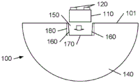
图1A-1B图示了具有促进气泡和粘合剂的离开的通道和倾斜壁的透镜结构的示例轮廓和底视图。
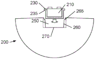
图2图示了具有阶梯状且倾斜的壁的透镜结构的示例剖视图。
图3A和3B图示了具有锥形腔体的透镜结构的示例片。
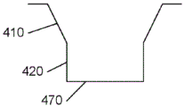
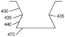
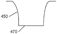
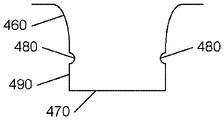
图4A-4D图示了复杂锥形腔体的示例轮廓。
图5图示了具有圆锥曲线腔体的透镜结构的示例底视图。
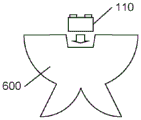
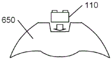
图6A和6B图示了可替换的光学元件。
贯穿附图,相同的参考标号指示相似或对应的特征或功能。出于说明性目的而包括附图并且附图不旨在限制本发明的范围。
具体实施方式
在以下描述中,出于解释而非限制的目的,阐述具体细节,诸如特定架构、接口、技术等,以便提供对本发明的概念的透彻理解。然而,本领域技术人员将显而易见的是,本发明可以在偏离这些具体细节的其它实施例中实践。以类似方式,该描述的文本针对如在附图中图示的示例实施例,并且不旨在将所要求保护的发明限制成超出明确包括在权利要求中的限度。出于简明和清楚的目的,省略了公知的设备、电路和方法的详细描述,以便不以非必要细节使本发明的描述模糊。
图1A-1B图示了透镜100的示例轮廓和底视图,透镜100包括用于接收发光设备(LED)110的腔体150,以及在从LED 100发射光时提供期望的光输出图案的光学元件140。在该示例中,光学元件140是半球形圆顶,其跨其视场提供基本均匀的光输出图案。
透镜100可以包括硅树脂、硅树脂环氧树脂混合物、玻璃或者具有适当折射率的任何透明光学材料。LED 110可以是诸如芯片级包装(CSP)之类的自支撑设备,或者安装在陶瓷衬底上的薄膜管芯(陶瓷上管芯,DOC),其中在与发光表面130相对的表面上具有接触件120。还可以使用其它LED结构。
如所图示的,为了便于组装,腔体150为锥形并且包括倾斜壁160。基于所预期的应用的要求,腔体150的底表面170经尺寸设计以便使发光设备110在给定精度内位于腔体150内的固定位置处。在该示例中,底表面170具有与发光设备基本相同的尺寸,尽管其可以稍微大一些,这取决于发光设备的容差。发光设备110关于透镜结构100的位置的所要求的精度可以支配底表面170的可允许的过度的大小调整(over-sizing),如果有的话。
在将LED 100插入到腔体中之前,具有与LED 110或透镜100的折射率相等或者为在LED 110和透镜100的折射率之间的值的折射率的粘合剂可以分散到腔体150中。取决于特定组装技术,粘合剂还可以或者可替换地可以在插入到腔体150中之前分散到LED 110上。
如图1A和1B中所图示的,可以提供通道180以使得空气和过量粘合剂能够在组装过程期间逃离。这些通道180在图1A和1B中被图示为圆柱钻孔,尽管可以使用其它形状;例如,如果腔体通过成型过程形成,则通道可以具有与倾斜壁160相同的倾斜度。
通道180图示在腔体150的每一个角落处,尽管可以提供其它位置以及更少或者更多的通道。在一个可替换方案中,可以使用位于LED 100的侧面且远离角落的通道来避免旋转对准误差。通道的大小、形状和位置可以取决于多个因素而更改,包括例如粘合剂的黏度和LED 110的总体大小。
在另一实施例中,在腔体150的底表面170和发光表面130之间没有粘合剂的情况下,将LED 110插入到腔体中。可以使用折射率匹配液体的薄膜来提供LED 110与底表面170之间的高效光学耦合。在插入之后,可以在LED 110与倾斜壁160之间的空间中施用粘合剂。粘合剂的这种后插入应用可以消除或者最小化对通道180的需要。
为了便于具有LED 110的透镜100在后续衬底(诸如印刷电路板)上的后续安装,可以确定腔体150的深度,使得当发光设备完全位于腔体内时,触头120稍微延伸到透镜100的底侧101上方(“凸出于底侧101之上”)。比LED 110(包括接触件120)的总高度小大约50-500um的深度一般提供接触件超出透镜100的底侧101的充分凸出,尽管可以使用其它深度,这取决于应用的容差要求。例如,如果LED 110是具有精细容差的自支撑芯片级包装,则可以使用像5um那么小的标称凸出。
通过将锥形物成形以使得腔体150的开口大于LED 110的尺寸,LED 110到腔体150中的插入得以简化。通过将锥形物成形以使得腔体150的截面在朝向底表面170的方向上变窄,LED 110在透镜100内的位置的变化基本上得到控制,从而在LED 110被插入到透镜110时提供该LED 110的自对准。该锥形物还独立于用于将LED 110插入到腔体150中的构件而提供这种自对准。甚至LED 110到腔体150中的手动插入将提供与使用高度准确且精准的拾取和放置机器的自动化插入相同的准确度和精度。以类似方式,可以使用最小准确度和精度的拾取和放置机器,而同时仍旧维持相同高水平的准确度和精度。
如图2中所图示的,透镜200的腔体250的轮廓可以调节成符合发光设备210的形状。在该示例中,发光设备210包括波长转换层230,诸如在发光设备210上成型的磷光体嵌入的硅树脂。在腔体250的入口处的凹陷265被成形以容纳由该示例波长转换层230形成的唇缘235。
在凹陷265下方,腔体250包括促进发光设备210的插入的倾斜壁260,以及用于将发光设备在给定精度内定位在透镜200内的底表面270,如以上关于透镜100的表面170所详述的。
图3A和3B图示了具有腔体150的透镜100、100'的示例片300、300'。尽管仅图示了几个透镜100、100',但是本领域技术人员将认识到,片300、300'可以包括数百个透镜100、100'。为了便于说明,没有图示图1A-1B的每一个腔体150的排气通道180,但是其可以存在。
在图3A的示例中,片300包括十六个透镜100,每一个具有单个腔体150。该片可以包括例如硅树脂、硅树脂环氧树脂混合物、玻璃或者可以以限定的腔体形成的任何其它透明光学材料。
在示例制造过程中,拾取和放置机器可以用于将每一个LED 110(未图示)插入到每一个腔体150中。拾取和放置机器可以配置成将每一个LED 110放置在每一个腔体150的中心处,但是在插入期间具有充分的顺从性(compliance)以使得LED 110能够由腔体150的壁引导到期望的位置中。可替换地,拾取和放置机器可以将每一个LED 110部分地放置到每一个腔体150中,并且诸如板压之类的后续过程可以用于完成LED 110到腔体150中的插入。
在可替换过程中,LED在适当的位置处布置于临时衬底上,诸如常规“切分带”,并且通过将片300覆盖在LED上或者通过使具有所附连的LED的切分带覆盖在片300之上来将片300与衬底上的这些LED配对。
在示例实施例中,片300是部分固化的硅树脂,其在LED 110被插入到每一个腔体150中之后固化。随后的固化可以用于将每一个LED 110粘附到每一个透镜100,从而避免需要包括粘结。
在可替换实施例中,片300完全形成,并且可以将粘合剂应用于每一个腔体150或者每一个LED 110,以将每一个LED 110固设到每一个透镜100。在一些实施例中,在将LED110插入到腔体150之后应用粘合剂,从而将LED 110的边缘粘附到腔体150的壁。
在下文详述的其它实施例中,片300可以包括具有某种弹性的材料,并且LED 110到腔体150中的插入可以提供充足的摩擦力以将LED 110维持在透镜100内的适当位置处。
促进LED 110的发光表面与片300的透镜100之间的光学耦合的材料可以应用于腔体150或者LED 110。
以类似方式,用于反射照射LED 110的边缘的光的材料可以应用于LED 110的边缘,例如通过利用这样的材料填充LED 110与腔体150的倾斜壁之间的间隙。
在完成LED 110在透镜100的腔体150中的插入和粘附之后,可以沿切割线320-370切割切分片300以提供具有透镜组件的单一化LED。在一些实施例中,具有透镜的多个LED可以被提供为单个组件,例如通过仅沿线330和360切割,从而提供四个组件,每一个组装包括具有单独的透镜的四个LED。
本领域技术人员将认识到,先前各图的LED和透镜之间的示例性一对一关系仅仅是许多配置中的一种。例如,图3B图示了其中预期将多个LED插入到每一个透镜100'的多个腔体150中的实施例。在这样的实施例中,每一个透镜100'的腔体150可以比图3A的每一个透镜100的腔体150更加紧密地定位。
在一些实施例中,腔体150中的一个或多个可以配置成容纳多个LED管芯,其可以布置在单个衬底上。在其它实施例中,每一个透镜100'内的腔体150可以具有不同大小,以容纳透镜100'内不同LED类型的混合,诸如不同颜色LED的组合。
如在图3A的示例中,LED 110(未图示)可以手动地或者经由拾取和放置过程插入到每一个腔体中。或者,LED 110可以在对应于片300'上的腔体150的位置处布置于临时衬底上,并且随后将片300'与包含LED 110的衬底配对。类似地,可以使用任何以上所述技术或者任何其它可行且可靠的技术来将LED 110粘附到透镜100'。
当完成LED 110到每一个透镜100'的腔体150中的插入和粘附之后,可以通过沿切割线380、390切割/切分片300'来单一化透镜100'。
考虑到本公开内容,本领域技术人员将认识到,本发明不限于具有线性倾斜壁160的腔体150的示例使用。
图4A-4D图示了可替换的腔体轮廓。如在图3A-3B中,图1的排气通道180没有在这些图中图示以便于说明,但是可以包括在每一个示例实施例中。
图4A图示了包括具有不同倾斜度的壁分段410、420的轮廓。上部壁分段410具有相对浅的倾斜度以提供用于插入LED(未图示)的宽开口,而壁分段420具有相对陡的倾斜度并且可以与表面470正交,以提供用于压缩LED的边缘的较大表面区域来维持LED在腔体内的恰当位置。
取决于形成腔体的材料、LED的大小和表面470的大小之间的配合的紧密度、下部壁分段420的倾斜度以及排气通道180(未图示)的大小,该实施例可能要求很大的力量来将每一个LED插入到每一个腔体中。图4B-4D图示了可能要求较小的插入力的可替换轮廓。
在图4B中,上部壁分段430倾斜以提供比预期的LED的大小更大的开口,并且下部壁分段420在相反的方向上倾斜以创建用于压缩LED的边缘的突起435来维持LED在腔体内的恰当位置。然而,如相比于图4A,LED的边缘将仅接触这些突起435,而不是下部壁分段440的整个表面。壁分段440的反向倾斜提供比包含在突起435之间的LED更宽的下表面470,从而提供用于移位的空气或粘合剂的一些空间、减少或消除对排气通道180的依赖。
在图4C中,弯曲壁分段450用于以非线性方式逐渐减小表面470的方向上的截面区域,使得壁分段450的下部可以比图1的线性倾斜壁160更多地约束LED,但是比图4A的线性壁分段420更少地约束,特别是如果分段420与表面470正交的话。相比于图4A的壁分段410和420之间的过渡处的突变边缘,壁分段450的连续曲率还可以使LED的插入便利。
图4D图示了弯曲460和线性490壁分段的组合,以及可以在引入最小插入阻力的同时固定LED的特征480的添加。特征480可以是腔体内的连续脊状物,或者来自壁分段490的多个单独的珠状突起。如果使用单独的突起,则减少了插入阻力,并且突起之间的空间允许移位的空气和粘合剂逃离,从而潜在地避免对于图1的排气通道180的需要。
鉴于本公开内容,本领域技术人员将认识到,可以使用各种各样的其它轮廓中任意一种来在给定容差内固定透镜内的LED的位置,而同时还允许实用的插入力。
本领域技术人员还可以认识到,腔体的形状或者腔体的表面的形状不需要匹配LED的形状。取决于用于创建透镜的过程和材料,创建比如在图1B中所示的矩形腔体可能在经济上不是可行的。如果例如透镜是刚性材料,那么对圆形腔体钻孔或研磨可能远不如创建矩形腔体昂贵。
图5图示了包括具有形成圆形底表面570的倾斜壁560的圆锥形腔体550的示例透镜500。表面570的直径使得其包围LED 110,从而提供腔体的壁上的接触点590,其使LED110定心在表面570的中心处。LED 110周围的半圆形间隙575允许移位的空气和粘合剂逃离,从而潜在地避免对于图1的排气通道180的需要。
与图1B的矩形表面170对照,圆锥形腔体550和圆形表面570可以允许LED 110在插入过程期间旋转,但是如果透镜500的光学性质是关于中心轴对称的,则LED 110围绕该中心轴的旋转将对于将LED 110定位在该中心轴处的准确度和精度没有影响。如果透镜500是部分固化的硅树脂,则部分固化的硅树脂的顺从性可以使得LED 100能够“刺入”到角落590处的硅树脂,由此控制或限制旋转。
重要的是要指出,以上全部示例剖视图也可以是圆锥形腔体的半部的剖视图,尽管图4B和4D的轮廓将更可能通过成型过程而不是钻孔或研磨过程形成,并且经由成型过程实现矩形腔体是相对简明直接的。
本领域技术人员还将认识到,透镜的光学元件不限于图1A-1B的半球形圆顶140。图6A和6B分别图示了示例侧发射式光学元件600和示例准直光学元件650。可以使用其它光学元件来实现期望的光输出图案。
尽管已经在附图和前面的描述中详细图示和描述了本发明,但是这样的图示和描述要被视为说明性或示例性的而非限制性的;本发明不限于所公开的实施例。
例如,可能在其中附加元件可以包括于腔体内的实施例中操作本发明。例如,波长转换材料可以在发光设备被插入之前插入到腔体中。可替换地或者此外,透镜可以包括波长转换材料,或者发光设备可以包括波长转换材料。在一些实施例中,波长转换材料可以用作发光设备与透镜之间的粘结层。
通过研究附图、公开内容和随附权利要求,本领域技术人员在实践所要求保护的发明时,可以理解和实现对所公开的实施例的其它变形。在权利要求中,词语“包括”不排除其它元件或步骤,并且不定冠词“一”不排除多个。在相互不同的从属权利要求中记载某些措施的仅有事实不指示这些措施的组合不能用户获益。权利要求中的任何附图标记不应当解释为限制范围。
Claims (15)
1.一种透镜结构,包括:
具有接收发光设备的开口的腔体,该腔体具有锥形物,使得腔体内的截面区域小于开口的区域,以及
光学元件,其在被腔体内的发光设备照射时提供特定光输出图案。
2.权利要求1所述的透镜结构,其中锥形物包括线性倾斜的一个或多个壁。
3.权利要求2所述的透镜结构,其中锥形物使得发光设备布置在透镜结构内的固定位置处。
4.权利要求1所述的透镜结构,其中腔体的深度使得发光设备的电接触件在发光设备完全插入到腔体中时从腔体突出。
5.权利要求1所述的透镜结构,其中锥形物包括复合形式。
6.权利要求1所述的透镜结构,其中锥形物包括一个或多个弯曲壁。
7.权利要求1所述的透镜结构,包括在发光设备插入在腔体中时允许材料的移位的一个或多个通道。
8.权利要求1所述的透镜结构,包括用于减小截面区域的腔体内的一个或多个突起。
9.权利要求1所述的透镜结构,包括发光设备以及在腔体的壁与发光设备的边缘之间的反射材料。
10.一种片,包括:
多个透镜结构,每一个透镜结构具有用于接收发光元件的一个或多个锥形腔体以及在发光元件发射光时提供特定光输出图案的光学元件,
其中每一个锥形腔体具有用于接收发光元件的开口、发光元件光学耦合到的表面以及比开口的截面区域更小的至少一个截面区域。
11.权利要求10所述的片,其中该片包括硅树脂材料。
12.权利要求11所述的片,其中该片包括位于每一个腔体中的多个发光元件,并且硅树脂材料处于部分固化的状态中。
13.权利要求10所述的片,其中该片包括玻璃。
14.一种用于创建发光产品的方法,包括:
提供包括多个透镜结构的片,每一个透镜结构具有用于接收发光元件的一个或多个锥形腔体以及在发光元件发射光时提供特定光输出图案的光学元件,并且每一个锥形腔体具有用于接收发光元件的开口、发光元件光学耦合到的表面以及比开口的截面区域更小的至少一个截面区域;
将发光元件插入到每一个锥形腔体中;以及
将具有对应发光元件的透镜结构单一化以形成发光产品。
15.权利要求14所述的方法,其中该片包括在发光元件插入到腔体中时处于至少部分固化的状态中的硅树脂,并且该方法包括在发光元件插入到腔体中之后固化硅树脂。
Applications Claiming Priority (3)
| Application Number | Priority Date | Filing Date | Title |
|---|---|---|---|
| US201461930586P | 2014-01-23 | 2014-01-23 | |
| US61/930586 | 2014-01-23 | ||
| CN201580005512.XA CN105940262B (zh) | 2014-01-23 | 2015-01-04 | 具有自对准预制透镜的发光设备 |
Related Parent Applications (1)
| Application Number | Title | Priority Date | Filing Date |
|---|---|---|---|
| CN201580005512.XA Division CN105940262B (zh) | 2014-01-23 | 2015-01-04 | 具有自对准预制透镜的发光设备 |
Publications (1)
| Publication Number | Publication Date |
|---|---|
| CN111063787A true CN111063787A (zh) | 2020-04-24 |
Family
ID=52396775
Family Applications (2)
| Application Number | Title | Priority Date | Filing Date |
|---|---|---|---|
| CN201911355103.9A Pending CN111063787A (zh) | 2014-01-23 | 2015-01-04 | 具有自对准预制透镜的发光设备 |
| CN201580005512.XA Active CN105940262B (zh) | 2014-01-23 | 2015-01-04 | 具有自对准预制透镜的发光设备 |
Family Applications After (1)
| Application Number | Title | Priority Date | Filing Date |
|---|---|---|---|
| CN201580005512.XA Active CN105940262B (zh) | 2014-01-23 | 2015-01-04 | 具有自对准预制透镜的发光设备 |
Country Status (6)
| Country | Link |
|---|---|
| US (3) | US10416356B2 (zh) |
| EP (1) | EP3097351A1 (zh) |
| JP (2) | JP2017504215A (zh) |
| KR (1) | KR102217791B1 (zh) |
| CN (2) | CN111063787A (zh) |
| WO (1) | WO2015110927A1 (zh) |
Cited By (1)
| Publication number | Priority date | Publication date | Assignee | Title |
|---|---|---|---|---|
| US10895669B2 (en) | 2014-01-23 | 2021-01-19 | Lumileds Llc | Light emitting device with self-aligning preformed lens |
Families Citing this family (5)
| Publication number | Priority date | Publication date | Assignee | Title |
|---|---|---|---|---|
| JP6645781B2 (ja) * | 2015-09-11 | 2020-02-14 | アルパッド株式会社 | 半導体発光装置 |
| US10340173B2 (en) * | 2016-10-11 | 2019-07-02 | Micron Technology, Inc. | System for handling semiconductor dies |
| DE102017122325A1 (de) | 2017-09-26 | 2019-03-28 | Osram Opto Semiconductors Gmbh | Strahlungsemittierendes Halbleiterbauelement und Verfahren zur Herstellung von strahlungsemittierenden Halbleiterbauelementen |
| KR20190120715A (ko) * | 2018-04-16 | 2019-10-24 | 리지텍 일렉트로닉스 컴퍼니 리미티드 | 구조화된 광 투사 시스템 |
| EP3832199A1 (en) * | 2019-12-06 | 2021-06-09 | Marelli Automotive Lighting Italy S.p.A. | Automotive lighting and/or signaling device and related assembly method |
Citations (26)
| Publication number | Priority date | Publication date | Assignee | Title |
|---|---|---|---|---|
| US20010026011A1 (en) * | 1999-03-15 | 2001-10-04 | Roberts John K. | Radiation emitter devices and method of making the same |
| US20020080615A1 (en) * | 2000-12-22 | 2002-06-27 | Thomas Marshall | LED collimation optics with improved performance and reduced size |
| US20020163808A1 (en) * | 2001-05-04 | 2002-11-07 | West Robert S. | Lens and Lens Cap with Sawtooth Portion for Light Emitting Diode |
| US20020163810A1 (en) * | 2001-05-04 | 2002-11-07 | West Robert S. | Side emitting LED |
| JP2005159149A (ja) * | 2003-11-27 | 2005-06-16 | Aoki Denki Kogyo Kk | 高輝度led発光部 |
| CN1726410A (zh) * | 2002-10-11 | 2006-01-25 | 光处方革新有限公司 | 密致折叠型光学元件照明透镜 |
| US20060078246A1 (en) * | 2004-10-07 | 2006-04-13 | Towa Corporation | Transparent member, optical device using transparent member and method of manufacturing optical device |
| JP2007059618A (ja) * | 2005-08-24 | 2007-03-08 | Matsushita Electric Works Ltd | Led照明器具 |
| CN1934722A (zh) * | 2004-03-24 | 2007-03-21 | 东芝照明技术株式会社 | 照明装置 |
| US7349163B2 (en) * | 2001-12-06 | 2008-03-25 | Fraen Corporation S.R.L. | High-heat-dissipation lighting module |
| CN101240885A (zh) * | 2007-12-10 | 2008-08-13 | 王敏 | Led小角度远距离送光镜组及阵列 |
| US20080203415A1 (en) * | 2007-02-13 | 2008-08-28 | 3M Innovative Properties Company | Led devices having lenses and methods of making same |
| US20080283861A1 (en) * | 2004-06-04 | 2008-11-20 | Cree, Inc. | Power light emitting die package with reflecting lens and the method of making the same |
| CN101636851A (zh) * | 2007-02-26 | 2010-01-27 | 皇家菲利浦电子有限公司 | 具有透镜中的磷光体片和过模压磷光体的led |
| JP2010170734A (ja) * | 2009-01-20 | 2010-08-05 | Panasonic Electric Works Co Ltd | Led照明装置 |
| US7874703B2 (en) * | 2008-08-28 | 2011-01-25 | Dialight Corporation | Total internal reflection lens with base |
| CN102017199A (zh) * | 2008-04-24 | 2011-04-13 | 松下电工株式会社 | 具有透镜的发光单元 |
| CN102052630A (zh) * | 2009-11-09 | 2011-05-11 | 富准精密工业(深圳)有限公司 | 发光组件 |
| JP2011113755A (ja) * | 2009-11-25 | 2011-06-09 | Panasonic Electric Works Co Ltd | 発光装置 |
| CN102563525A (zh) * | 2010-11-10 | 2012-07-11 | 三星Led株式会社 | 闪光灯透镜和闪光灯模块 |
| CN102686935A (zh) * | 2009-12-21 | 2012-09-19 | 马丁专业公司 | 具有互补中心透镜和外围透镜的集光器 |
| CN102800797A (zh) * | 2011-05-24 | 2012-11-28 | 台湾积体电路制造股份有限公司 | 具有远离荧光结构的蝙蝠翼透镜 |
| US20130039050A1 (en) * | 2011-08-08 | 2013-02-14 | Quarkstar, Llc | Solid-State Luminaire |
| CN103196040A (zh) * | 2012-01-06 | 2013-07-10 | 扬升照明股份有限公司 | 透镜结构、光源装置以及光源模块 |
| US20130235581A1 (en) * | 2010-10-27 | 2013-09-12 | Dbm Reflex Enterprises Inc. | Lens array assembly for solid state light sources and method |
| US20140377894A1 (en) * | 2013-06-25 | 2014-12-25 | Samsung Electronics Co., Ltd. | Method of manufacturing semiconductor light emitting device package |
Family Cites Families (41)
| Publication number | Priority date | Publication date | Assignee | Title |
|---|---|---|---|---|
| NO143045B (no) | 1975-05-16 | Kolbjoern Bjoershol | Apparat for kroksetting av en fiskeline. | |
| JPS5860954A (ja) * | 1981-10-07 | 1983-04-11 | Asahimatsu Shokuhin Kk | 大豆タンパク凍結変性物のゲル状食品製造法 |
| JPS5860954U (ja) * | 1981-10-19 | 1983-04-25 | 株式会社リコー | 発光素子取付構造 |
| JPH0561790U (ja) * | 1992-01-21 | 1993-08-13 | セイコーエプソン株式会社 | 操作パネル |
| JPH06104491A (ja) | 1992-09-17 | 1994-04-15 | Rohm Co Ltd | 発光ダイオードランプ |
| JPH11204841A (ja) * | 1998-01-13 | 1999-07-30 | Nichia Chem Ind Ltd | 光半導体素子とその製造方法 |
| JP3349111B2 (ja) * | 1999-03-15 | 2002-11-20 | 株式会社シチズン電子 | 表面実装型発光ダイオード及びその製造方法 |
| JP3948650B2 (ja) | 2001-10-09 | 2007-07-25 | アバゴ・テクノロジーズ・イーシービーユー・アイピー(シンガポール)プライベート・リミテッド | 発光ダイオード及びその製造方法 |
| US7465961B2 (en) * | 2003-03-25 | 2008-12-16 | Sharp Kabushiki Kaisha | Electronic equipment, backlight structure and keypad for electronic equipment |
| US7009213B2 (en) * | 2003-07-31 | 2006-03-07 | Lumileds Lighting U.S., Llc | Light emitting devices with improved light extraction efficiency |
| JP4444609B2 (ja) | 2003-09-26 | 2010-03-31 | スタンレー電気株式会社 | Ledランプ及び製造方法 |
| US7452737B2 (en) | 2004-11-15 | 2008-11-18 | Philips Lumileds Lighting Company, Llc | Molded lens over LED die |
| KR100649640B1 (ko) * | 2005-02-03 | 2006-11-27 | 삼성전기주식회사 | 측면 방출형 발광다이오드 패키지 |
| TW200825529A (en) * | 2006-12-06 | 2008-06-16 | Chi Lin Technology Co Ltd | Light mixer and backlight module having it |
| WO2009039491A1 (en) * | 2007-09-21 | 2009-03-26 | Cooper Technologies Company | Light emitting diode recessed light fixture |
| CN101235953A (zh) * | 2008-03-04 | 2008-08-06 | 友达光电股份有限公司 | 透镜结构与发光单元 |
| EP2260341A2 (en) * | 2008-03-05 | 2010-12-15 | Oree, Advanced Illumination Solutions INC. | Illumination apparatus and methods of forming the same |
| DE102008025756B4 (de) * | 2008-05-29 | 2023-02-23 | OSRAM Opto Semiconductors Gesellschaft mit beschränkter Haftung | Halbleiteranordnung |
| BRPI0913195A2 (pt) | 2008-05-30 | 2016-01-12 | Sharp Kk | dispostivo emissor de luz, fonte de luz de superfície, dispositivo de vídeo de cristal líquido e método para a fabricação de dispositivo emissor de luz |
| CN101936501B (zh) * | 2009-06-30 | 2013-04-24 | 富准精密工业(深圳)有限公司 | 发光二极管模组 |
| US8803171B2 (en) * | 2009-07-22 | 2014-08-12 | Koninklijke Philips N.V. | Reduced color over angle variation LEDs |
| US9385285B2 (en) | 2009-09-17 | 2016-07-05 | Koninklijke Philips N.V. | LED module with high index lens |
| CN102062347A (zh) * | 2009-11-12 | 2011-05-18 | 富准精密工业(深圳)有限公司 | 发光二极管模组及其透镜 |
| JP5701502B2 (ja) | 2009-12-25 | 2015-04-15 | 日亜化学工業株式会社 | 発光装置 |
| JP5512262B2 (ja) | 2009-12-26 | 2014-06-04 | 株式会社朝日ラバー | レンズアレイシート及びそれのダイシング方法 |
| JP5449039B2 (ja) * | 2010-06-07 | 2014-03-19 | 株式会社東芝 | 半導体発光装置及びその製造方法 |
| US8597988B2 (en) * | 2010-11-18 | 2013-12-03 | Bridgelux, Inc. | System for flash-free overmolding of led array substrates |
| TW201233940A (en) | 2010-11-30 | 2012-08-16 | Wintek Corp | Light source for crystal lamp |
| EP2704221A4 (en) * | 2011-04-28 | 2014-10-15 | Asahi Rubber Inc | SEMICONDUCTOR ELEMENT WITH A LENS AND METHOD OF MANUFACTURING THEREOF |
| KR20120133264A (ko) * | 2011-05-31 | 2012-12-10 | 삼성전자주식회사 | 발광소자 렌즈, 이를 포함하는 발광소자 모듈 및 이를 이용한 발광소자 모듈의 제조방법 |
| WO2013084155A1 (en) | 2011-12-08 | 2013-06-13 | Koninklijke Philips Electronics N.V. | Forming thick metal layers on a semiconductor light emitting device |
| CN103187504A (zh) * | 2011-12-27 | 2013-07-03 | 展晶科技(深圳)有限公司 | 发光二极管封装结构 |
| US9688035B2 (en) * | 2012-01-16 | 2017-06-27 | Dow Corning Corporation | Optical article and method of forming |
| KR101386710B1 (ko) | 2012-04-05 | 2014-04-18 | 건국대학교 산학협력단 | 비환식 석시노글리칸의 용도 |
| US9349929B2 (en) * | 2012-05-31 | 2016-05-24 | Cree, Inc. | Light emitter packages, systems, and methods |
| TW201431127A (zh) * | 2013-01-29 | 2014-08-01 | Hon Hai Prec Ind Co Ltd | 發光二極體封裝結構及其製造方法 |
| US9318674B2 (en) * | 2013-02-05 | 2016-04-19 | Cree, Inc. | Submount-free light emitting diode (LED) components and methods of fabricating same |
| CN111063787A (zh) | 2014-01-23 | 2020-04-24 | 亮锐控股有限公司 | 具有自对准预制透镜的发光设备 |
| US10297731B2 (en) * | 2014-11-26 | 2019-05-21 | Bridgelux, Inc. | Light emitting diode constructions and methods for making the same |
| US10591134B2 (en) * | 2016-01-19 | 2020-03-17 | Lutron Ketra, Llc | Lens for improved color mixing and beam control of an LED light source |
| JP6104491B1 (ja) | 2017-01-20 | 2017-03-29 | 三菱日立パワーシステムズ株式会社 | 船舶用脱硫装置および該船舶用脱硫装置を搭載した船舶 |
-
2015
- 2015-01-04 CN CN201911355103.9A patent/CN111063787A/zh active Pending
- 2015-01-04 US US15/110,840 patent/US10416356B2/en active Active
- 2015-01-04 JP JP2016547552A patent/JP2017504215A/ja active Pending
- 2015-01-04 WO PCT/IB2015/050050 patent/WO2015110927A1/en active Application Filing
- 2015-01-04 CN CN201580005512.XA patent/CN105940262B/zh active Active
- 2015-01-04 EP EP15701247.7A patent/EP3097351A1/en not_active Withdrawn
- 2015-01-04 KR KR1020167023018A patent/KR102217791B1/ko active IP Right Grant
-
2019
- 2019-09-16 US US16/572,074 patent/US10895669B2/en active Active
-
2020
- 2020-09-30 JP JP2020164629A patent/JP2021002682A/ja active Pending
-
2021
- 2021-01-14 US US17/149,129 patent/US11313996B2/en active Active
Patent Citations (28)
| Publication number | Priority date | Publication date | Assignee | Title |
|---|---|---|---|---|
| US20030168670A1 (en) * | 1999-03-15 | 2003-09-11 | Roberts John K. | Method of making radiation emitter devices |
| US20010026011A1 (en) * | 1999-03-15 | 2001-10-04 | Roberts John K. | Radiation emitter devices and method of making the same |
| US20020080615A1 (en) * | 2000-12-22 | 2002-06-27 | Thomas Marshall | LED collimation optics with improved performance and reduced size |
| CN1404630A (zh) * | 2000-12-22 | 2003-03-19 | 皇家菲利浦电子有限公司 | Led模块 |
| US20020163808A1 (en) * | 2001-05-04 | 2002-11-07 | West Robert S. | Lens and Lens Cap with Sawtooth Portion for Light Emitting Diode |
| US20020163810A1 (en) * | 2001-05-04 | 2002-11-07 | West Robert S. | Side emitting LED |
| US7349163B2 (en) * | 2001-12-06 | 2008-03-25 | Fraen Corporation S.R.L. | High-heat-dissipation lighting module |
| CN1726410A (zh) * | 2002-10-11 | 2006-01-25 | 光处方革新有限公司 | 密致折叠型光学元件照明透镜 |
| JP2005159149A (ja) * | 2003-11-27 | 2005-06-16 | Aoki Denki Kogyo Kk | 高輝度led発光部 |
| CN1934722A (zh) * | 2004-03-24 | 2007-03-21 | 东芝照明技术株式会社 | 照明装置 |
| US20080283861A1 (en) * | 2004-06-04 | 2008-11-20 | Cree, Inc. | Power light emitting die package with reflecting lens and the method of making the same |
| US20060078246A1 (en) * | 2004-10-07 | 2006-04-13 | Towa Corporation | Transparent member, optical device using transparent member and method of manufacturing optical device |
| JP2007059618A (ja) * | 2005-08-24 | 2007-03-08 | Matsushita Electric Works Ltd | Led照明器具 |
| US20080203415A1 (en) * | 2007-02-13 | 2008-08-28 | 3M Innovative Properties Company | Led devices having lenses and methods of making same |
| CN101636851A (zh) * | 2007-02-26 | 2010-01-27 | 皇家菲利浦电子有限公司 | 具有透镜中的磷光体片和过模压磷光体的led |
| CN101240885A (zh) * | 2007-12-10 | 2008-08-13 | 王敏 | Led小角度远距离送光镜组及阵列 |
| CN102017199A (zh) * | 2008-04-24 | 2011-04-13 | 松下电工株式会社 | 具有透镜的发光单元 |
| US7874703B2 (en) * | 2008-08-28 | 2011-01-25 | Dialight Corporation | Total internal reflection lens with base |
| JP2010170734A (ja) * | 2009-01-20 | 2010-08-05 | Panasonic Electric Works Co Ltd | Led照明装置 |
| CN102052630A (zh) * | 2009-11-09 | 2011-05-11 | 富准精密工业(深圳)有限公司 | 发光组件 |
| JP2011113755A (ja) * | 2009-11-25 | 2011-06-09 | Panasonic Electric Works Co Ltd | 発光装置 |
| CN102686935A (zh) * | 2009-12-21 | 2012-09-19 | 马丁专业公司 | 具有互补中心透镜和外围透镜的集光器 |
| US20130235581A1 (en) * | 2010-10-27 | 2013-09-12 | Dbm Reflex Enterprises Inc. | Lens array assembly for solid state light sources and method |
| CN102563525A (zh) * | 2010-11-10 | 2012-07-11 | 三星Led株式会社 | 闪光灯透镜和闪光灯模块 |
| CN102800797A (zh) * | 2011-05-24 | 2012-11-28 | 台湾积体电路制造股份有限公司 | 具有远离荧光结构的蝙蝠翼透镜 |
| US20130039050A1 (en) * | 2011-08-08 | 2013-02-14 | Quarkstar, Llc | Solid-State Luminaire |
| CN103196040A (zh) * | 2012-01-06 | 2013-07-10 | 扬升照明股份有限公司 | 透镜结构、光源装置以及光源模块 |
| US20140377894A1 (en) * | 2013-06-25 | 2014-12-25 | Samsung Electronics Co., Ltd. | Method of manufacturing semiconductor light emitting device package |
Cited By (2)
| Publication number | Priority date | Publication date | Assignee | Title |
|---|---|---|---|---|
| US10895669B2 (en) | 2014-01-23 | 2021-01-19 | Lumileds Llc | Light emitting device with self-aligning preformed lens |
| US11313996B2 (en) | 2014-01-23 | 2022-04-26 | Lumileds Llc | Light emitting device with self-aligning preformed lens |
Also Published As
| Publication number | Publication date |
|---|---|
| CN105940262A (zh) | 2016-09-14 |
| EP3097351A1 (en) | 2016-11-30 |
| JP2017504215A (ja) | 2017-02-02 |
| JP2021002682A (ja) | 2021-01-07 |
| CN105940262B (zh) | 2020-01-07 |
| US11313996B2 (en) | 2022-04-26 |
| US20160341852A1 (en) | 2016-11-24 |
| KR20160113198A (ko) | 2016-09-28 |
| US20200116902A1 (en) | 2020-04-16 |
| US20210132263A1 (en) | 2021-05-06 |
| WO2015110927A1 (en) | 2015-07-30 |
| KR102217791B1 (ko) | 2021-02-22 |
| US10895669B2 (en) | 2021-01-19 |
| US10416356B2 (en) | 2019-09-17 |
Similar Documents
| Publication | Publication Date | Title |
|---|---|---|
| US11313996B2 (en) | Light emitting device with self-aligning preformed lens | |
| US9018663B2 (en) | Lens-equipped optical semiconductor device and method for manufacturing the same | |
| KR101219106B1 (ko) | 발광소자 패키지 및 그 제조방법 | |
| JP4744573B2 (ja) | 電子装置の製造方法 | |
| TWI408835B (zh) | 發光二極體晶粒上之上層模製 | |
| EP3044809B1 (en) | Frame based package for flip-chip led | |
| EP2666193B1 (en) | Led package comprising encapsulation | |
| TW201042780A (en) | Compact molded LED module | |
| US20150287891A1 (en) | LED Packaging Structure Using Distant Fluorescent Powder Layer and Manufacturing Method Thereof | |
| EP2177337B1 (en) | Optical device molding system | |
| EP2973759B1 (en) | Encapsulating led lens with bottom reflectors | |
| CN105393372A (zh) | 具有内部高折射率柱的led圆顶 | |
| US8828754B2 (en) | Method for manufacturing LED | |
| CN105845790A (zh) | 一种倒装led芯片的封装方法及封装槽模具 | |
| US8956893B2 (en) | Metiod of making LED with bat-wing emitting field lens | |
| JP5189925B2 (ja) | レンズ部材の製造方法 | |
| CN117239018A (zh) | 一种紫外led器件的制备方法 |
Legal Events
| Date | Code | Title | Description |
|---|---|---|---|
| PB01 | Publication | ||
| PB01 | Publication | ||
| SE01 | Entry into force of request for substantive examination | ||
| SE01 | Entry into force of request for substantive examination | ||
| WD01 | Invention patent application deemed withdrawn after publication |
Application publication date: 20200424 |
|
| WD01 | Invention patent application deemed withdrawn after publication |
