EP3325917B1 - Detector for optically detecting at least one object - Google Patents
Detector for optically detecting at least one object Download PDFInfo
- Publication number
- EP3325917B1 EP3325917B1 EP16742213.8A EP16742213A EP3325917B1 EP 3325917 B1 EP3325917 B1 EP 3325917B1 EP 16742213 A EP16742213 A EP 16742213A EP 3325917 B1 EP3325917 B1 EP 3325917B1
- Authority
- EP
- European Patent Office
- Prior art keywords
- detector
- pixels
- nonlinear
- light
- present
- Prior art date
- Legal status (The legal status is an assumption and is not a legal conclusion. Google has not performed a legal analysis and makes no representation as to the accuracy of the status listed.)
- Active
Links
- 230000003287 optical effect Effects 0.000 claims description 269
- 238000011156 evaluation Methods 0.000 claims description 120
- 238000005286 illumination Methods 0.000 claims description 110
- 238000005259 measurement Methods 0.000 claims description 62
- 238000000034 method Methods 0.000 claims description 47
- 239000011159 matrix material Substances 0.000 claims description 46
- 238000012546 transfer Methods 0.000 claims description 42
- 238000005516 engineering process Methods 0.000 claims description 26
- 238000004519 manufacturing process Methods 0.000 claims description 24
- 238000001514 detection method Methods 0.000 claims description 22
- 230000001902 propagating effect Effects 0.000 claims description 10
- 230000004044 response Effects 0.000 claims description 9
- 238000012937 correction Methods 0.000 claims description 8
- 238000003908 quality control method Methods 0.000 claims description 7
- 238000012886 linear function Methods 0.000 claims description 5
- 230000001131 transforming effect Effects 0.000 claims description 2
- 230000006870 function Effects 0.000 description 84
- 230000003595 spectral effect Effects 0.000 description 39
- 238000012545 processing Methods 0.000 description 32
- 238000003384 imaging method Methods 0.000 description 22
- 230000033001 locomotion Effects 0.000 description 16
- 230000035945 sensitivity Effects 0.000 description 16
- 230000000694 effects Effects 0.000 description 14
- 230000010354 integration Effects 0.000 description 14
- 239000000463 material Substances 0.000 description 14
- 230000008859 change Effects 0.000 description 12
- 230000005670 electromagnetic radiation Effects 0.000 description 12
- 238000007689 inspection Methods 0.000 description 12
- 230000036961 partial effect Effects 0.000 description 11
- 230000008901 benefit Effects 0.000 description 10
- 239000007788 liquid Substances 0.000 description 10
- 238000010276 construction Methods 0.000 description 8
- 230000014509 gene expression Effects 0.000 description 8
- 230000008569 process Effects 0.000 description 8
- 230000003190 augmentative effect Effects 0.000 description 7
- 238000004891 communication Methods 0.000 description 7
- 230000001419 dependent effect Effects 0.000 description 7
- 238000012544 monitoring process Methods 0.000 description 7
- 238000010521 absorption reaction Methods 0.000 description 6
- 241001465754 Metazoa Species 0.000 description 5
- 230000009471 action Effects 0.000 description 5
- 230000001976 improved effect Effects 0.000 description 5
- 230000000051 modifying effect Effects 0.000 description 5
- 238000007781 pre-processing Methods 0.000 description 5
- 238000004422 calculation algorithm Methods 0.000 description 4
- 239000000470 constituent Substances 0.000 description 4
- 230000003247 decreasing effect Effects 0.000 description 4
- 238000013461 design Methods 0.000 description 4
- 238000004088 simulation Methods 0.000 description 4
- 239000000126 substance Substances 0.000 description 4
- 238000012549 training Methods 0.000 description 4
- 238000002604 ultrasonography Methods 0.000 description 4
- 241000196324 Embryophyta Species 0.000 description 3
- 241000282412 Homo Species 0.000 description 3
- 230000001133 acceleration Effects 0.000 description 3
- 238000004458 analytical method Methods 0.000 description 3
- 238000011161 development Methods 0.000 description 3
- 230000018109 developmental process Effects 0.000 description 3
- 238000003745 diagnosis Methods 0.000 description 3
- 238000005265 energy consumption Methods 0.000 description 3
- 230000001815 facial effect Effects 0.000 description 3
- 231100001261 hazardous Toxicity 0.000 description 3
- 230000036541 health Effects 0.000 description 3
- 230000003993 interaction Effects 0.000 description 3
- 230000000670 limiting effect Effects 0.000 description 3
- 238000012423 maintenance Methods 0.000 description 3
- 238000007726 management method Methods 0.000 description 3
- 238000010606 normalization Methods 0.000 description 3
- 239000004065 semiconductor Substances 0.000 description 3
- 239000007787 solid Substances 0.000 description 3
- 238000001356 surgical procedure Methods 0.000 description 3
- 230000009466 transformation Effects 0.000 description 3
- 238000005406 washing Methods 0.000 description 3
- 238000010146 3D printing Methods 0.000 description 2
- 239000011358 absorbing material Substances 0.000 description 2
- 230000004075 alteration Effects 0.000 description 2
- 238000013459 approach Methods 0.000 description 2
- 238000000429 assembly Methods 0.000 description 2
- 230000006399 behavior Effects 0.000 description 2
- 230000005540 biological transmission Effects 0.000 description 2
- 238000004364 calculation method Methods 0.000 description 2
- 238000011088 calibration curve Methods 0.000 description 2
- 238000004140 cleaning Methods 0.000 description 2
- 230000000295 complement effect Effects 0.000 description 2
- 238000004590 computer program Methods 0.000 description 2
- 238000002316 cosmetic surgery Methods 0.000 description 2
- 244000038559 crop plants Species 0.000 description 2
- 230000006378 damage Effects 0.000 description 2
- 239000000975 dye Substances 0.000 description 2
- 229920001746 electroactive polymer Polymers 0.000 description 2
- 238000002474 experimental method Methods 0.000 description 2
- 235000013305 food Nutrition 0.000 description 2
- 239000011521 glass Substances 0.000 description 2
- 238000003306 harvesting Methods 0.000 description 2
- 239000000383 hazardous chemical Substances 0.000 description 2
- 238000010438 heat treatment Methods 0.000 description 2
- 238000010409 ironing Methods 0.000 description 2
- 238000005065 mining Methods 0.000 description 2
- 229930014626 natural product Natural products 0.000 description 2
- 238000010397 one-hybrid screening Methods 0.000 description 2
- 239000011368 organic material Substances 0.000 description 2
- 238000004806 packaging method and process Methods 0.000 description 2
- 230000000737 periodic effect Effects 0.000 description 2
- 230000002093 peripheral effect Effects 0.000 description 2
- 238000001454 recorded image Methods 0.000 description 2
- 230000002829 reductive effect Effects 0.000 description 2
- 238000012552 review Methods 0.000 description 2
- 238000007493 shaping process Methods 0.000 description 2
- 230000003068 static effect Effects 0.000 description 2
- 230000000007 visual effect Effects 0.000 description 2
- 239000002699 waste material Substances 0.000 description 2
- 239000002023 wood Substances 0.000 description 2
- LHMQDVIHBXWNII-UHFFFAOYSA-N 3-amino-4-methoxy-n-phenylbenzamide Chemical compound C1=C(N)C(OC)=CC=C1C(=O)NC1=CC=CC=C1 LHMQDVIHBXWNII-UHFFFAOYSA-N 0.000 description 1
- 241000894006 Bacteria Species 0.000 description 1
- 241000538562 Banjos Species 0.000 description 1
- 241000282994 Cervidae Species 0.000 description 1
- 241001077262 Conga Species 0.000 description 1
- 241000282326 Felis catus Species 0.000 description 1
- 241000233866 Fungi Species 0.000 description 1
- 241000238631 Hexapoda Species 0.000 description 1
- 208000030858 Myofascial Pain Syndromes Diseases 0.000 description 1
- 206010028980 Neoplasm Diseases 0.000 description 1
- 241000577979 Peromyscus spicilegus Species 0.000 description 1
- 238000001069 Raman spectroscopy Methods 0.000 description 1
- 229910000831 Steel Inorganic materials 0.000 description 1
- 241000982634 Tragelaphus eurycerus Species 0.000 description 1
- 241000405217 Viola <butterfly> Species 0.000 description 1
- 241000700605 Viruses Species 0.000 description 1
- 241000607479 Yersinia pestis Species 0.000 description 1
- 238000000862 absorption spectrum Methods 0.000 description 1
- 230000003044 adaptive effect Effects 0.000 description 1
- 239000000654 additive Substances 0.000 description 1
- 230000000996 additive effect Effects 0.000 description 1
- 238000012271 agricultural production Methods 0.000 description 1
- 238000004378 air conditioning Methods 0.000 description 1
- 238000003491 array Methods 0.000 description 1
- 230000000712 assembly Effects 0.000 description 1
- 238000007681 bariatric surgery Methods 0.000 description 1
- 239000012472 biological sample Substances 0.000 description 1
- 208000022266 body dysmorphic disease Diseases 0.000 description 1
- 210000004556 brain Anatomy 0.000 description 1
- 201000011510 cancer Diseases 0.000 description 1
- 239000003795 chemical substances by application Substances 0.000 description 1
- 238000005352 clarification Methods 0.000 description 1
- 239000003086 colorant Substances 0.000 description 1
- 238000004624 confocal microscopy Methods 0.000 description 1
- 238000001816 cooling Methods 0.000 description 1
- 239000002537 cosmetic Substances 0.000 description 1
- 239000013078 crystal Substances 0.000 description 1
- 238000005520 cutting process Methods 0.000 description 1
- 238000013500 data storage Methods 0.000 description 1
- 229920005994 diacetyl cellulose Polymers 0.000 description 1
- 238000002059 diagnostic imaging Methods 0.000 description 1
- 201000010099 disease Diseases 0.000 description 1
- 208000037265 diseases, disorders, signs and symptoms Diseases 0.000 description 1
- 239000003814 drug Substances 0.000 description 1
- 230000005684 electric field Effects 0.000 description 1
- 230000008030 elimination Effects 0.000 description 1
- 238000003379 elimination reaction Methods 0.000 description 1
- 230000007613 environmental effect Effects 0.000 description 1
- 239000003344 environmental pollutant Substances 0.000 description 1
- 238000012854 evaluation process Methods 0.000 description 1
- 230000008921 facial expression Effects 0.000 description 1
- 239000003337 fertilizer Substances 0.000 description 1
- 238000001914 filtration Methods 0.000 description 1
- 230000004907 flux Effects 0.000 description 1
- -1 food or wood Natural products 0.000 description 1
- 230000010196 hermaphroditism Effects 0.000 description 1
- 238000010348 incorporation Methods 0.000 description 1
- 208000015181 infectious disease Diseases 0.000 description 1
- 230000002458 infectious effect Effects 0.000 description 1
- 230000000977 initiatory effect Effects 0.000 description 1
- 229910010272 inorganic material Inorganic materials 0.000 description 1
- 239000011147 inorganic material Substances 0.000 description 1
- 230000007794 irritation Effects 0.000 description 1
- 230000009191 jumping Effects 0.000 description 1
- 238000004020 luminiscence type Methods 0.000 description 1
- 239000000696 magnetic material Substances 0.000 description 1
- 238000002595 magnetic resonance imaging Methods 0.000 description 1
- 238000013507 mapping Methods 0.000 description 1
- 235000013372 meat Nutrition 0.000 description 1
- 230000007246 mechanism Effects 0.000 description 1
- 238000012986 modification Methods 0.000 description 1
- 230000004048 modification Effects 0.000 description 1
- 239000013307 optical fiber Substances 0.000 description 1
- 238000000399 optical microscopy Methods 0.000 description 1
- 210000000056 organ Anatomy 0.000 description 1
- 238000012856 packing Methods 0.000 description 1
- 230000037361 pathway Effects 0.000 description 1
- 238000003909 pattern recognition Methods 0.000 description 1
- 238000009527 percussion Methods 0.000 description 1
- 238000000554 physical therapy Methods 0.000 description 1
- 230000008635 plant growth Effects 0.000 description 1
- 230000010287 polarization Effects 0.000 description 1
- 231100000719 pollutant Toxicity 0.000 description 1
- 229920000642 polymer Polymers 0.000 description 1
- 238000004886 process control Methods 0.000 description 1
- 230000005855 radiation Effects 0.000 description 1
- 230000002285 radioactive effect Effects 0.000 description 1
- 239000012857 radioactive material Substances 0.000 description 1
- 230000011514 reflex Effects 0.000 description 1
- 238000000926 separation method Methods 0.000 description 1
- 208000037974 severe injury Diseases 0.000 description 1
- 230000009528 severe injury Effects 0.000 description 1
- 230000007480 spreading Effects 0.000 description 1
- 238000003892 spreading Methods 0.000 description 1
- 239000010959 steel Substances 0.000 description 1
- 238000003860 storage Methods 0.000 description 1
- 230000008093 supporting effect Effects 0.000 description 1
- 238000010408 sweeping Methods 0.000 description 1
- 230000009182 swimming Effects 0.000 description 1
- 238000001931 thermography Methods 0.000 description 1
- 230000036962 time dependent Effects 0.000 description 1
- 230000007704 transition Effects 0.000 description 1
- 238000011282 treatment Methods 0.000 description 1
- 238000012285 ultrasound imaging Methods 0.000 description 1
- 235000013311 vegetables Nutrition 0.000 description 1
- 238000012795 verification Methods 0.000 description 1
- 238000012800 visualization Methods 0.000 description 1
- XLYOFNOQVPJJNP-UHFFFAOYSA-N water Substances O XLYOFNOQVPJJNP-UHFFFAOYSA-N 0.000 description 1
- 238000009736 wetting Methods 0.000 description 1
Images

Classifications
-
- G—PHYSICS
- G06—COMPUTING; CALCULATING OR COUNTING
- G06F—ELECTRIC DIGITAL DATA PROCESSING
- G06F3/00—Input arrangements for transferring data to be processed into a form capable of being handled by the computer; Output arrangements for transferring data from processing unit to output unit, e.g. interface arrangements
- G06F3/01—Input arrangements or combined input and output arrangements for interaction between user and computer
- G06F3/03—Arrangements for converting the position or the displacement of a member into a coded form
- G06F3/0304—Detection arrangements using opto-electronic means
- G06F3/0325—Detection arrangements using opto-electronic means using a plurality of light emitters or reflectors or a plurality of detectors forming a reference frame from which to derive the orientation of the object, e.g. by triangulation or on the basis of reference deformation in the picked up image
-
- G—PHYSICS
- G01—MEASURING; TESTING
- G01S—RADIO DIRECTION-FINDING; RADIO NAVIGATION; DETERMINING DISTANCE OR VELOCITY BY USE OF RADIO WAVES; LOCATING OR PRESENCE-DETECTING BY USE OF THE REFLECTION OR RERADIATION OF RADIO WAVES; ANALOGOUS ARRANGEMENTS USING OTHER WAVES
- G01S5/00—Position-fixing by co-ordinating two or more direction or position line determinations; Position-fixing by co-ordinating two or more distance determinations
- G01S5/16—Position-fixing by co-ordinating two or more direction or position line determinations; Position-fixing by co-ordinating two or more distance determinations using electromagnetic waves other than radio waves
-
- G—PHYSICS
- G01—MEASURING; TESTING
- G01C—MEASURING DISTANCES, LEVELS OR BEARINGS; SURVEYING; NAVIGATION; GYROSCOPIC INSTRUMENTS; PHOTOGRAMMETRY OR VIDEOGRAMMETRY
- G01C3/00—Measuring distances in line of sight; Optical rangefinders
- G01C3/02—Details
- G01C3/06—Use of electric means to obtain final indication
- G01C3/08—Use of electric radiation detectors
-
- G—PHYSICS
- G01—MEASURING; TESTING
- G01C—MEASURING DISTANCES, LEVELS OR BEARINGS; SURVEYING; NAVIGATION; GYROSCOPIC INSTRUMENTS; PHOTOGRAMMETRY OR VIDEOGRAMMETRY
- G01C3/00—Measuring distances in line of sight; Optical rangefinders
- G01C3/32—Measuring distances in line of sight; Optical rangefinders by focusing the object, e.g. on a ground glass screen
-
- G—PHYSICS
- G01—MEASURING; TESTING
- G01S—RADIO DIRECTION-FINDING; RADIO NAVIGATION; DETERMINING DISTANCE OR VELOCITY BY USE OF RADIO WAVES; LOCATING OR PRESENCE-DETECTING BY USE OF THE REFLECTION OR RERADIATION OF RADIO WAVES; ANALOGOUS ARRANGEMENTS USING OTHER WAVES
- G01S11/00—Systems for determining distance or velocity not using reflection or reradiation
- G01S11/12—Systems for determining distance or velocity not using reflection or reradiation using electromagnetic waves other than radio waves
-
- G—PHYSICS
- G01—MEASURING; TESTING
- G01S—RADIO DIRECTION-FINDING; RADIO NAVIGATION; DETERMINING DISTANCE OR VELOCITY BY USE OF RADIO WAVES; LOCATING OR PRESENCE-DETECTING BY USE OF THE REFLECTION OR RERADIATION OF RADIO WAVES; ANALOGOUS ARRANGEMENTS USING OTHER WAVES
- G01S17/00—Systems using the reflection or reradiation of electromagnetic waves other than radio waves, e.g. lidar systems
- G01S17/02—Systems using the reflection of electromagnetic waves other than radio waves
- G01S17/06—Systems determining position data of a target
- G01S17/46—Indirect determination of position data
-
- G—PHYSICS
- G01—MEASURING; TESTING
- G01S—RADIO DIRECTION-FINDING; RADIO NAVIGATION; DETERMINING DISTANCE OR VELOCITY BY USE OF RADIO WAVES; LOCATING OR PRESENCE-DETECTING BY USE OF THE REFLECTION OR RERADIATION OF RADIO WAVES; ANALOGOUS ARRANGEMENTS USING OTHER WAVES
- G01S17/00—Systems using the reflection or reradiation of electromagnetic waves other than radio waves, e.g. lidar systems
- G01S17/66—Tracking systems using electromagnetic waves other than radio waves
-
- G—PHYSICS
- G01—MEASURING; TESTING
- G01S—RADIO DIRECTION-FINDING; RADIO NAVIGATION; DETERMINING DISTANCE OR VELOCITY BY USE OF RADIO WAVES; LOCATING OR PRESENCE-DETECTING BY USE OF THE REFLECTION OR RERADIATION OF RADIO WAVES; ANALOGOUS ARRANGEMENTS USING OTHER WAVES
- G01S3/00—Direction-finders for determining the direction from which infrasonic, sonic, ultrasonic, or electromagnetic waves, or particle emission, not having a directional significance, are being received
- G01S3/78—Direction-finders for determining the direction from which infrasonic, sonic, ultrasonic, or electromagnetic waves, or particle emission, not having a directional significance, are being received using electromagnetic waves other than radio waves
- G01S3/782—Systems for determining direction or deviation from predetermined direction
- G01S3/783—Systems for determining direction or deviation from predetermined direction using amplitude comparison of signals derived from static detectors or detector systems
- G01S3/784—Systems for determining direction or deviation from predetermined direction using amplitude comparison of signals derived from static detectors or detector systems using a mosaic of detectors
-
- G—PHYSICS
- G01—MEASURING; TESTING
- G01S—RADIO DIRECTION-FINDING; RADIO NAVIGATION; DETERMINING DISTANCE OR VELOCITY BY USE OF RADIO WAVES; LOCATING OR PRESENCE-DETECTING BY USE OF THE REFLECTION OR RERADIATION OF RADIO WAVES; ANALOGOUS ARRANGEMENTS USING OTHER WAVES
- G01S7/00—Details of systems according to groups G01S13/00, G01S15/00, G01S17/00
- G01S7/48—Details of systems according to groups G01S13/00, G01S15/00, G01S17/00 of systems according to group G01S17/00
- G01S7/481—Constructional features, e.g. arrangements of optical elements
- G01S7/4816—Constructional features, e.g. arrangements of optical elements of receivers alone
-
- G—PHYSICS
- G06—COMPUTING; CALCULATING OR COUNTING
- G06T—IMAGE DATA PROCESSING OR GENERATION, IN GENERAL
- G06T2207/00—Indexing scheme for image analysis or image enhancement
- G06T2207/30—Subject of image; Context of image processing
- G06T2207/30204—Marker
Definitions
- the invention relates to a detector, a detector system and a method for determining a position of at least one object.
- the invention further relates to a human-machine interface for exchanging at least one item of information between a user and a machine, an entertainment device, a tracking system, a camera, a scanning system and various uses of the detector device.
- the devices, systems, methods and uses according to the present invention specifically may be employed for example in various areas of daily life, gaming, traffic technology, production technology, security technology, photography such as digital photography or video photography for arts, documentation or technical purposes, medical technology or in the sciences. However, other applications are also possible.
- photovoltaic devices are generally used to convert electromagnetic radiation, for example, ultraviolet, visible or infrared light, into electrical signals or electrical energy
- optical detectors are generally used for picking up image information and/or for detecting at least one optical parameter, for example, a brightness.
- sensors which can be based generally on the use of inorganic and/or organic sensor materials are known from the prior art. Examples of such sensors are disclosed in US 2007/0176165A1 , US 6,995,445 B2 , DE 2501124 A1 , DE 3225372 A1 or else in numerous other prior art documents. To an increasing extent, in particular for cost reasons and for reasons of large-area processing, sensors comprising at least one organic sensor material are being used, as described for example in US 2007/0176165 A1 . In particular, so-called dye solar cells are increasingly of importance here, which are described generally, for example in WO 2009/013282 A1 . The present invention, however, is not restricted to the use of organic devices. Thus, specifically, also inorganic devices such as CCD sensors and/or CMOS sensors, specifically pixelated sensors, may be employed.
- detectors for detecting at least one object are known on the basis of such optical sensors.
- Such detectors can be embodied in diverse ways, depending on the respective purpose of use.
- Examples of such detectors are imaging devices, for example, cameras and/or microscopes.
- High-resolution confocal microscopes are known, for example, which can be used in particular in the field of medical technology and biology in order to examine biological samples with high optical resolution.
- Further examples of detectors for optically detecting at least one object are distance measuring devices based, for example, on propagation time methods of corresponding optical signals, for example laser pulses.
- Further examples of detectors for optically detecting objects are triangulation systems, by means of which distance measurements can likewise be carried out.
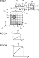
- a detector for optically detecting at least one object comprises at least one optical sensor.
- the optical sensor has at least one sensor region.
- the optical sensor is designed to generate at least one sensor signal in a manner dependent on an illumination of the sensor region.
- the sensor signal given the same total power of the illumination, is dependent on a geometry of the illumination, in particular on a beam cross section of the illumination on the sensor area.
- the detector furthermore has at least one evaluation device.
- the evaluation device is designed to generate at least one item of geometrical information from the sensor signal, in particular at least one item of geometrical information about the illumination and/or the object.
- WO 2014/097181 A1 discloses a method and a detector for determining a position of at least one object, by using at least one transversal optical sensor and at least one optical sensor. Specifically, the use of sensor stacks is disclosed, in order to determine a longitudinal position of the object with a high degree of accuracy and without ambiguity.
- WO 2015/024871 A1 discloses an optical detector, comprising:
- WO 2014/198629 A1 discloses a detector for determining a position of at least one object, comprising:
- EP 15 153 215.7 filed on January 30, 2015
- EP 15 157 363.1 filed on March 3, 2015
- EP 15 164 653.6 filed on April 22, 2015 .
- US 2014/347442 describes a pixel array which includes color pixels that have a layout, and depth pixels having a layout that starts from the layout of the color pixels. Photodiodes of adjacent depth pixels can be joined to form larger depth pixels, while still efficiently exploiting the layout of the color pixels.
- 3D-sensing concepts are at least partially based on using so-called FiP sensors, such as several of the above-mentioned concepts.
- FiP sensors such as several of the above-mentioned concepts.
- large area sensors may be used, in which the individual sensor pixels are significantly larger than the light spot and which are fixed to a specific size.
- large area sensors in many cases are inherently limited in the use of the FiP measurement principle, specifically in case more than one light spot is to be investigated simultaneously.
- pixelated optical sensors may be used, such as in the pixel counting concepts disclosed in WO 2014/198629 A1 . Even though these concepts allow for an efficient determination of 3D coordinates and even though these concepts are significantly superior to known 3D sensing concepts such as triangulation, some challenges remain, specifically regarding the need for calculating power and resources, as well as increasing the efficiency. Generally, it might also be desirable to employ commonly available optical sensors, such as CCD and/or CMOS sensors.
- the terms “have”, “comprise” or “include” or any arbitrary grammatical variations thereof are used in a non-exclusive way. Thus, these terms may both refer to a situation in which, besides the feature introduced by these terms, no further features are present in the entity described in this context and to a situation in which one or more further features are present.
- the expressions “A has B”, “A comprises B” and “A includes B” may both refer to a situation in which, besides B, no other element is present in A (i.e. a situation in which A solely and exclusively consists of B) and to a situation in which, besides B, one or more further elements are present in entity A, such as element C, elements C and D or even further elements.
- the terms "at least one”, “one or more” or similar expressions indicating that a feature or element may be present once or more than once typically will be used only once when introducing the respective feature or element.
- the expressions “at least one” or “one or more” will not be repeated, non-withstanding the fact that the respective feature or element may be present once or more than once.
- a detector for determining a position of at least one object is disclosed.
- the term "position" refers to at least one item of information regarding a location and/or orientation of the object and/or at least one part of the object in space.
- the at least one item of information may imply at least one distance between at least one point of the object and the at least one detector.
- the distance may be a longitudinal coordinate or may contribute to determining a longitudinal coordinate of the point of the object.
- one or more other items of information regarding the location and/or orientation of the object and/or at least one part of the object may be determined.
- At least one transversal coordinate of the object and/or at least one part of the object may be determined.
- the position of the object may imply at least one longitudinal coordinate of the object and/or at least one part of the object.
- the position of the object may imply at least one transversal coordinate of the object and/or at least one part of the object.
- the position of the object may imply at least one orientation information of the object, indicating an orientation of the object in space.
- the detector comprises:
- an optical sensor generally refers to a light-sensitive device for detecting a light beam, such as for detecting an illumination and/or a light spot generated by a light beam.
- the optical sensor may be adapted, as outlined in further detail below, to determine at least one longitudinal coordinate of the object and/or of at least one part of the object, such as at least one part of the object from which the at least one light beam travels towards the detector.
- a pixel generally refers to a light-sensitive element of the optical sensor, such as a minimum unit of the optical sensor adapted to generate a light signal.
- each pixel may have a light-sensitive area of 1 ⁇ m 2 to 5 000 000 ⁇ m 2 , preferably 1 ⁇ m 2 to 4 000 000 ⁇ m 2 , preferably 1 ⁇ m 2 to 1 000 000 ⁇ m 2 and more preferably 1 ⁇ m 2 to 5 000 ⁇ m 2 .
- the expression matrix generally refers to an arrangement of a plurality of the pixels in space, which may be a linear arrangement or an areal arrangement.
- the matrix preferably may be selected from the group consisting of a one-dimensional matrix and a two-dimensional matrix.
- the matrix may comprise 100 to 100 000 000 pixels, preferably 1 000 to 10 000 000 pixels and, more preferably, 100 000 to 5 000 000 pixels.
- the matrix is a rectangular matrix having pixels arranged in rows and columns. Still, other matrix arrangements are feasible, such as circular or hexagonal arrangements.
- a pixel signal generally refers to an arbitrary memorable and transferable signal which is generated by the pixels, in response to the illumination.
- the pixel signal may be or may comprise at least one electronic signal, which may be or may comprise a digital electronic signal and/or an analogue electronic signal.
- the pixel signal may be or may comprise at least one voltage signal and/or at least one current signal.
- either raw pixel signals may be used, or the detector, the optical sensor or any other element may be adapted to process or preprocess the pixel signals, thereby generating secondary pixel signals, which may also be used as pixel signals, such as preprocessing by filtering or the like.
- the pixel signals symbolically are denoted by s i,j .
- the indices i and j denote integers which indicate coordinates of the respective pixel, such that each pixel uniquely may be identified by its coordinates i, j.
- the matrix may be a rectangular n x m matrix, with n, m being integers, such that i, j may denote Cartesian coordinates of the pixels with i ⁇ ⁇ 1, ..., n ⁇ and j ⁇ ⁇ 1, ..., m ⁇ .
- the matrix may be a circular matrix, having a plurality of concentric rings of pixels, with i denoting a number of the ring and j denoting a specific pixel within the ring, or vice versa.
- Other coordinate systems are feasible.
- the same nomenclature codes hold true for the nonlinear pixel signals s' i,j , since each of the nonlinear pixel signals corresponds to a specific pixel signal. Further, the same nomenclature with indices i, j holds true for the power of the illumination p i,j of the pixels.
- the pixel signals specifically may be proportional to the intensity of the illumination of the respective pixels, at least within a range of measurement, such as up to a predetermined or determinable maximum intensity.
- the detector may comprise one or more attenuating elements, such as one or more filter elements.
- the term non-linearization device generally refers to an arbitrary device, which transforms at least one input signal into at least one output signal, wherein the output signal is non-proportional to the input signal.
- the output signal is not a linear function of the input signal.
- the detector may be adapted to feed the pixel signals s i,j of all pixels i, j or of at least one group of pixels into the at least one non-linearization device as input signals, and the non-linearization device renders corresponding nonlinear pixel signals s' i,j as output signals.
- the non-linearization device may fully or partially be implemented by hardware or may fully or partially be implemented by an appropriate software running on a computer, such as a processor and/or an application-specific integrated circuit. Further, the non-linearization device may fully or partially be integrated into one or more other components of the detector, such as into the optical sensor and/or into the summing device and/or into the evaluation device. Alternatively, however, the non-linearization device may also be embodied as a separate, independent component. Further, one or more dedicated non-linearization devices may be provided for each pixel. Alternatively, however, two or more or even all of the pixels may share one or more common non-linearization devices.
- one or more Gamma correction devices may be used as non-linearization devices, which are generally known in the art of display technology and/or camera technology.
- the transformation of the pixel signals into the nonlinear pixel signals may be performed for all of the pixels or for one or more groups of pixels.
- the detector such as one or more of the non-linearization device, the summing device, the evaluation device or any other component of the detector, may be adapted to define at least one region of interest, wherein the pixels within the region of interest are defined as pixels belonging to the at least one group.
- one or more switches may be used.
- the transformation of the pixel signals into the nonlinear pixel signals and/or the adding up of the nonlinear pixel signals may be performed for the selected pixels belonging to the at least one group, only, such as by switching on these pixels and/or by switching a connection between these pixels and the non-linearization device and/or the summing device.
- Other embodiments are feasible.
- a summing device generally refers to an arbitrary device which is configured to add to one or more signals, specifically electrical signals, such as digital signals and/or analogue signals. In case a very high number of pixels of pixel density is given, the adding up of the pixels may correspond to an integration over the matrix and/or at least one part of the matrix.
- the summing device may fully or partially be embodied by hardware and/or may fully or partially be embodied by software running on a computer. In the art of electronics, summing devices are generally known to the skilled person.
- the term evaluation device generally refers to an arbitrary device adapted to perform the named operations, preferably by using at least one data processing device and, more preferably, by using at least one processor and/or at least one application-specific integrated circuit.
- the at least one evaluation device may comprise at least one data processing device having a software code stored thereon comprising a number of computer commands.
- the evaluation device may be configured to determine the at least one longitudinal coordinate z of the object by using at least one known, determinable or predetermined relationship between the nonlinear sum signal and the longitudinal coordinate.
- the sum signal is a linear function of the overall power of illumination P, i.e. is independent from the size d of the light spot generated by the light beam on the optical sensor.
- s ′ i , j g p i , j , with g being a nonlinear function, such as a polynomial function with a degree > 1, an exponential function, a logarithmic function, a root function, such as a square root function, a trigonometric function, a hyperbolic function, a Gaussian function, an error function, or a further special function.
- the nonlinear function may further be a piecewise-defined function defined by multiple sub-functions.
- the nonlinear function is preferably monotonically increasing in the intensity range of interest.
- a linear optical sensor may be used, in which equation (1) holds true, at least within a predetermined measurement range.
- nonlinear functions c such as exponential functions, logarithmic functions, root functions, such as a square root function, trigonometric functions, hyperbolic functions, Gaussian functions, error functions, or further special functions, polynomial functions or a Gamma function such as used for Gamma correction in display technology and/or camera technology may be used.
- the nonlinear functions may further be piecewise-defined functions, defined by multiple sub-functions, or may be a sum, product, convolution or the like, of linear and nonlinear functions.
- the nonlinear functions are preferably monotonically increasing or decreasing in the intensity range of interest.
- nonlinear Sum signal S is a function of the size d of the light spot.
- a spreading of a constant energy or power of radiation over a larger or smaller number of pixels, i.e. over a larger or smaller light spot, will modify the nonlinear sum signal S'.
- a predetermined or determinable relationship between S' and d and/or S' and z may be used.
- This relationship in the most simple case, may be derived empirically, such as by monitoring the nonlinear sum signals S' for a plurality of experiments in which the longitudinal coordinate z is varied.
- a list or lookup table may be generated, in which spot sizes d and/or longitudinal coordinates z are listed for a plurality of nonlinear sum signals S'.
- analytical or semi-analytical approaches may be used for determining the relationship between S' and d and/or S' and z, such as by using theoretical Gaussian wave optical considerations and/or by using simulations such as FEM simulations.
- the method may be used in case the total power P of the illumination is unknown or even non-constant.
- a plurality of optical sensors may be used, and the results may be normalized for the total power P.
- the sum signal S may be determined, according to equation (2) above, and the total power P may be derived thereof, or, additionally or alternatively, the sum signal S may be used for normalizing the results of the nonlinear sum signal S'. Thereby, the same case as above with known total power P of illumination may be generated.
- the longitudinal coordinate z may be derived, or, which shall also be comprised by the term "longitudinal coordinate", any other raw measurement value or secondary measurement value which corresponds to the longitudinal coordinate or from which the longitudinal coordinate may be derived.
- the size d of the light spot may be used, which corresponds to the longitudinal coordinate and/or from which the longitudinal coordinate may be derived.
- the beam radius w of the transversal profile of the Gaussian light beam generally representing a Gaussian curve is defined, for a specific z-value, as a specific distance from the z-axis at which the amplitude E has dropped to a value of 1/e (approx. 36%) and at which the intensity I has dropped to 1/ e 2 .
- the minimum beam radius, which, in the Gaussian equation given above (which may also occur at other z -values, such as when performing a z-coordinate transformation), occurs at coordinate z 0, is denoted by w 0 .
- the beam radius generally follows equation (4) as given above, when the light beam propagates along the z-axis.
- determining the longitudinal coordinate may imply directly determining the longitudinal coordinate z, may imply determining one or more parameters defining the size of the light spot or may imply both, simultaneously or in a stepwise fashion.
- the above-mentioned operations are performed by the at least one evaluation device.
- one or more of the above-mentioned relationships may be implemented in software and/or hardware, such as by implementing one or more lookup tables.
- the evaluation device may comprise one or more programmable devices such as one or more computers, application-specific integrated circuits (ASICs) or Field Programmable Gate Arrays (FPGAs) which are configured to perform the above-mentioned evaluation, in order to determine the at least one longitudinal coordinate of the object by evaluating the nonlinear sum signal. Additionally or alternatively, however, the evaluation device may also fully or partially be embodied by hardware.
- two or more of the above-mentioned devices may fully or partially be integrated into one or more devices.
- the non-linearization device may fully or partially be integrated into the optical sensor, as is the case e.g. in many non-linearization devices integrated into CCD or CMOS camera chips for the purpose of Gamma correction.
- the summing device and/or the evaluation device may fully or partially be integrated into the optical sensor.
- the non-linearization device and the summing device may fully or partially be integrated into a common device which performs both functions and which, as an example, may comprise one or more hardware components such as one or more ASICs and/or one or more FPGAs. Additionally or alternatively, the non-linearization device and/or the summing device may also fully or partially be integrated into the evaluation device, such as by implementing one or more of their functions by using software components.
- the degree of integration may also have an impact on the speed of evaluation and the maximum frequency.
- the detector may also fully or partially be embodied as a camera and/or may be used in a camera, suited for acquiring standstill images or suited for acquiring video clips.
- a hardware integration may be preferable, such as by fully or partially implementing the summing device by using hardware components such as one or more operational amplifiers for summing analogue signals and/or by using one or more digital summing devices such as one or more electronic adders such as Carry-Ripple adders, full adders or the like.
- one or more ASIC components and/or FPGAs may be used.
- the detector according to one or more of the above-mentioned embodiments may be modified and improved or even optimized in various ways, which will be briefly discussed in the following and which may also be implemented in various arbitrary combinations, as the skilled person will recognize.
- the evaluation device may be configured to determine the at least one longitudinal coordinate z of the object by using at least one predetermined relationship between the sum signal S' and the longitudinal coordinate z.
- the predetermined relationship specifically may be selected from the group consisting of an empiric relationship determined by recording sum signals for objects positioned at a plurality of longitudinal coordinates or an analytical relationship.
- the predetermined relationship may be based on the assumption of the light beam being a Gaussian light beam.
- the nonlinear function specifically may be selected from the group consisting of: a convex function; a concave function; a polynomial function; an exponential function, such as an exp(x)-function; a logarithmic function; a root function, such as a square root function sqrt(x); a further nonlinear function such as a special function; a Gamma correction function.
- the nonlinear function may further be a piecewise-defined function defined by multiple sub-functions.
- the nonlinear function may be monotonically increasing or decreasing in the intensity range of interest. Other examples are given above.
- an arbitrary parameter or combination of parameters may be used for denoting the size d of the light spot, as discussed above.
- a beam waist, a radius, a diameter, or any other parameter of this kind may be used, as explained above in the context of equation (4).
- the size d may be selected from the group consisting of: a diameter of the light spot; an equivalent diameter of the light spot, a beam waist of the light spot; a double beam waist of the light spot; a full width at half maximum of the intensity of the light spot.
- the detector specifically one or more of the optical sensor, the non-linearization device, the summing device or the evaluation device, further may be configured to select at least one region of interest within the matrix of the pixels, wherein the pixels within the region of interest form the at least one group of pixels.
- the region of interest may be a portion or a combination of portions of the matrix which contain an image of the object.
- a region of interest may be chosen in accordance with the results of the evaluation of the image, such as by choosing an area of the matrix which contains the image of the object, as a region of interest.
- choosing a region of interest within an image and for tracking certain objects within the image reference may be made, e.g., to WO 2015/024871 A1 .
- the detector may comprise a plurality of switches and may be configured to perform the selection by using the switches.
- the detector may comprise one or more summing devices, specifically fully or partially embodied in hardware, and a plurality of switches for selecting pixels for summing, wherein, by actuating the switches, specific pixels may be connected to the at least one summing device.
- the switches may be controlled by software, such as in response to the result of the image evaluation as discussed above.
- the optical sensor as outlined above, specifically may be configured such that, at least within a predetermined range of measurement, specifically within a predetermined range of intensity of the illumination of the optical sensor and/or of each pixel, the pixel s i,j signals of the pixels are a linear function of the power of the illumination p i,j of the respective pixel.
- a precise linearity may be given, wherein, possibly, also certain tolerances in linearity may be acceptable, such as a deviation from a precisely linear function of no more than 20%, preferably of no more than 10% and most preferably of no more than 5%.
- the sum signal S may be used as a standard and/or as a reference and/or for calibration purposes.
- the detector may be configured to additionally record the sum signal S.
- the evaluation device may be further configured to determine the at least one longitudinal coordinate z of the object by using the sum signal S.
- the sum signal S may be used for selecting an appropriate relationship, such as an appropriate value of the lookup table for the specific sum signal S and/or an appropriate calibration curve for the specific sum signal S and, thus, for the given total power P.
- the sum signal S may also be used for normalizing the nonlinear sum signal, such as by using the normalized sum signal S'/S for further evaluation and determination of the longitudinal coordinate.
- the evaluation device may be configured to use the sum signal S for normalizing the nonlinear sum signal for the overall power P of the illumination.
- the non-linearization device may comprise at least one hardware component, preferably at least one of a processor, an FPGA or an ASIC. Other embodiments or combinations of the named options are feasible.
- the non-linearization device may fully or partially be embodied in hardware and/or may fully or partially be embodied in software.
- the non-linearization device may be embodied as a software program running on a processor, specifically a processor of the evaluation device.
- Other embodiments are feasible, as discussed above.
- the summing device specifically may comprise at least one hardware component, selected from the group consisting of: an adder; a summer; a summing amplifier; an adder for analogue quantities; an adder for digital quantities.
- the summing device may fully or partially be embodied by using hardware and/or may fully or partially be embodied by using software, as discussed above.
- the summing device thus, may also at least partially be embodied as a software program running on a processor, specifically a processor of the evaluation device. Other embodiments are feasible.
- the detector may comprise a single optical sensor or a plurality of optical sensors.
- an ambiguity exists in the size of the light spot at equal distances before and after the focal point.
- more than one optical sensor may be used, wherein the optical sensors are positioned at different positions along one or more beam paths of the light beam.
- the evaluation device may be configured to determine the at least one longitudinal coordinate z of the object by evaluating the nonlinear sum signals S' of at least two of the optical sensors. At least two of the optical sensors may be positioned at different positions along at least one beam path of the light beam, such that an optical path length between the object and the at least two optical sensors is non-identical.
- the evaluation device specifically may be configured to use the nonlinear sum signals S' of at least two of the optical sensors for resolving ambiguities in a relationship between the sum signal S' and the longitudinal coordinate z.
- the optical sensors may be located in one and the same beam path, specifically in case one or more of the optical sensors are transparent or semi-transparent, or at least two of the optical sensors may be positioned in different partial beam paths of the detector.
- the beam path of the detector may be split into two or more partial beam paths, such as by using one or more beam splitting elements, specifically one or more semi-transparent mirrors and/or beam splitting cubes. Other embodiments are feasible.
- the optical sensors may have identical spectral sensitivities.
- at least two of the optical sensors may have differing spectral sensitivities, wherein the evaluation device, in the latter case, may be adapted to determine a color of the light beam by comparing sensor signals of the optical sensors having differing spectral sensitivities.
- the at least one optical sensor may be or may comprise at least one of an organic optical sensor, an inorganic optical sensor such as an inorganic semiconductor optical sensor, or a hybrid optical sensor comprising one or more organic materials and one or more inorganic materials.
- an organic optical sensor such as an organic optical sensor
- an inorganic optical sensor such as an inorganic semiconductor optical sensor
- a hybrid optical sensor comprising one or more organic materials and one or more inorganic materials.
- the at least one optical sensor may comprise one or more of a CCD device, a CMOS device, a photodetector array, a focal plane array or a bolometer array.
- array generally refers to a plurality of the named elements, arranged in a pattern, such as in a 1-dimensional or 2-dimensional matrix.
- the array specifically may be or may comprise a rectangular, circular, hexagonal or star-shaped pattern, specifically in a plane perpendicular to an optical axis of the detector.
- photodetector generally refers to an element capable of detecting electromagnetic radiation, specifically light in one or more of the ultraviolet, the visible or the infrared spectral range.
- the term "focal-plane array” generally refers to an image sensing device comprising an array of light-sensing elements such as pixels, arranged at the focal plane of a lens, such as a lens of an optional transfer device of the detector.
- the term “bolometer” refers to a device for measuring the power of incident electromagnetic radiation by using a temperature-dependent electrical resistance or resistor which is heated up by the electromagnetic radiation.
- the matrix of pixels specifically may be a rectangular matrix having at least one row and a plurality of columns of pixels or having a plurality of rows and at least one column of pixels.
- the matrix specifically may comprise at least 10 columns, preferably at least 100 columns, and wherein the matrix comprises at least 10 rows, preferably at least 100 rows.
- the detector is enabled to determine the at least one longitudinal coordinate of the object, including the option of determining the longitudinal coordinate of the whole object or of one or more parts thereof.
- other coordinates of the object including transversal coordinates and/or rotational coordinates, may be determined by the detector, specifically by the evaluation device.
- a transversal position of the light spot generated by the light beam may be evaluated, such as by determining coordinates of a center of the light spot and/or coordinates of a maximum intensity of the light spot, within the matrix of pixels.
- At least one transversal coordinate of the object may be determined by the evaluation device.
- the evaluation device may further be adapted to determine at least one transversal coordinate x, y of the object by determining a position of the light beam on the matrix of pixels.
- the detector according to the present invention as well as the other devices and the method proposed in the context of the present invention, specifically, may be considered as a software version of the so-called "FiP” effect which is explained in further detail in WO 2012/110924 A1 and/or in WO 2014/097181 A1 .
- "FiP" alludes to the effect that a signal i may be generated which, given the same total power P of the illumination, depends on the photon density, the photon flux and, thus, on the cross-section ⁇ (F) of the incident beam.
- the signal i may be replaced by the at least one nonlinear sum signal S' , and, thus, linear optical sensors may be used, and the FiP effect may be generated by simply summing the nonlinear pixel signals.
- the technique which is used in the context of the present invention may also be referred to as an "artificial FiP effect" or as a "software FiP effect", since the at least one optical sensor used herein may be a linear optical sensor, in conjunction with an artificial subsequent non-linearization by hardware and/or software.
- the detector according to the present invention will also be referred to as a "software FiP detector".
- the detector may further comprise one or more optical elements, such as one or more lenses and/or one or more refractive elements, one or more mirrors, one or more diaphragms or the like.
- optical elements which are adapted to modify the light beam, such as by modifying one or more of a beam parameter of the light beam, a width of the light beam or a direction of the light beam, in the following, will also be referred to as a transfer element.
- the detector may further comprise at least one transfer device, wherein the transfer device may be adapted to guide the light beam onto the optical sensor, such as by one or more of deflecting, focusing or defocusing the light beam.
- the transfer device may comprise one or more lenses and/or one or more curved mirrors and/or one or more other types of refractive elements.
- the at least one transfer device specifically may have at least one focal length.
- the focal length may be fixed or variable.
- one or more focused tunable lenses may be comprised in the at least one transfer device.
- European patent application number 14 196 944.4 filed on December 9, 2014 .
- the focus-tunable lenses disclosed therein may also be used in the at least one optional transfer device of the detector according to the present invention.
- the term "focus-tunable lens” generally refers to an optical element being adapted to modify a focal position of a light beam passing the focus-tunable lens in a controlled fashion.
- the focus-tunable lens may be or may comprise one or more lens elements such as one or more lenses and/or one or more curved mirrors, with an adjustable or tunable focal length.
- the one or more lenses may comprise one or more of a biconvex lens, a biconcave lens, a plano-convex lens, a plano-concave lens, a convex-concave lens, or a concave-convex lens.
- the one or more curved mirrors may be or may comprise one or more of a concave mirror, a convex mirror, or any other type of mirror having one or more curved reflective surfaces. Any arbitrary combination thereof is generally feasible, as the skilled person will recognize.
- a "focal position” generally refers to a position at which the light beam has the narrowest width. Still, the term “focal position” generally may refer to other beam parameters, such as a divergence, a Raleigh length or the like, as will be obvious to the person skilled in the art of optical design.
- the focus-tunable lens may be or may comprise at least one lens, the focal length of which may be changed or modified in a controlled fashion, such as by an external influence light, a control signal, a voltage or a current.
- the change in focal position may also be achieved by an optical element with switchable refractive index, which by itself may not be a focusing device, but which may change the focal point of a fixed focus lens when placed into the light beam.
- the term "in a controlled fashion” generally refers to the fact that the modification takes place due to an influence which may be exerted onto the focus-tunable lens, such that the actual focal position of the light beam passing the focus-tunable lens and/or the focal length of the focus-tunable lens may be adjusted to one or more desired values by exerting an external influence on to the focus-tunable lens, such as by applying a control signal to the focus-tunable lens, such as one or more of a digital control signal, an analog control signal, a control voltage or a control current.
- the focus-tunable lens may be or may comprise a lens element such as a lens or a curved mirror, the focal length of which may be adjusted by applying an appropriate control signal, such as an electrical control signal.
- focus-tunable lenses are known in the literature and are commercially available. As an example, reference may be made to the tunable lenses, preferably the electrically tunable lenses, as available by Optotune AG, CH-8953 Dietikon, Switzerland, which may be employed in the context of the present invention. Further, focus tunable lenses as commercially available from Varioptic, 69007 Lyon, France, may be used. For a review on focus-tunable lenses, specifically based on fluidic effects, reference may be made, e.g., to N.
- the focus-tunable lens may comprise at least one transparent shapeable material, preferably a shapeable material which may change its shape and, thus, may change its optical properties and/or optical interfaces due to an external influence, such as a mechanical influence and/or an electrical influence.
- An actuator exerting the influence may specifically be part of the focus-tunable lens.
- the focus tunable lens may have one or more ports for providing at least one control signal to the focus tunable lens, such as one or more electrical ports.
- the shapeable material may specifically be selected from the group consisting of a transparent liquid and a transparent organic material, preferably a polymer, more preferably an electroactive polymer. Still, combinations are possible.
- the shapeable material may comprise two different types of liquids, such as a hydrophilic liquid and a lipophilic liquid. Other types of materials are feasible.
- the focus-tunable lens may further comprise at least one actuator for shaping at least one interface of the shapeable material.
- the actuator specifically may be selected from the group consisting of a liquid actuator for controlling an amount of liquid in a lens zone of the focus-tunable lens or an electrical actuator adapted for electrically changing the shape of the interface of the shapeable material.
- focus-tunable lenses are electrostatic focus-tunable lenses.
- the focus-tunable lens may comprise at least one liquid and at least two electrodes, wherein the shape of at least one interface of the liquid is changeable by applying one or both of a voltage or a current to the electrodes, preferably by electro-wetting.
- the focus tunable lens may be based on a use of one or more electroactive polymers, the shape of which may be changed by applying a voltage and/or an electric field.
- a single focus-tunable lens or a plurality of focus-tunable lenses may be used.
- the focus-tunable lens may be or may comprise a single lens element or a plurality of single lens elements. Additionally or alternatively, a plurality of lens elements may be used which are interconnected, such as in one or more modules, each module having a plurality of focus-tunable lenses.
- the at least one focus-tunable lens may be or may comprise at least one lens array, such as a micro-lens array, such as disclosed in C.U. Murade et al., Optics Express, Vol. 20, No. 16, 18180-18187 (2012 ).
- Other embodiments are feasible, such as a single focus-tunable lens.
- the at least one focus-tunable lens may be used in various ways.
- ambiguities in the determination of the z coordinate may be resolved.
- a beam waist or beam diameter of a light beam specifically of a Gaussian ray, is symmetric before and after the focal point and, thus, an ambiguity exists in case the size of the light spot is determined in only one longitudinal position.
- the size of the light spot into different positions may be determined, which is also possible in the context of the present invention, in order to resolve the ambiguity and in order to determine the at least one z-coordinate of the object in a non-ambiguous fashion.
- two or more than two optical sensors may be used, which preferably are positioned at different positions along an optical beam path and/or which are positioned in different partial beam paths, as will be explained in further detail below.
- the at least one optional focus-tunable lens may be used, and an evaluation according to the present invention may take place with at least two different adjustments, i.e. at least two different focal positions of the at least one focus-tunable lens.
- the above-mentioned ambiguity may be resolved since the sizes of the beam spot measured, in one case, at a constant distance before the focal position and, in a second case, measured at the constant distance behind the focal position will behave differently when the focal position is changed.
- the size of the light spot will increase and in the other case decrease, or vice versa, as the skilled person easily may derive when looking at e.g. Figure 5A or 5B of WO 2014/097181 A1 .
- At least one focus-tunable lens can be used to record two or more images in a row, which, as an example, may be used as an input signal for the evaluation device.
- At least one focus-tunable lens can be used to record two or more images in a row, which, as an example, may be used as an input signal for the evaluation device.
- a detector or a camera with only one beam path may be realized, such as by recording two or more images in a row with different lens focus of the at least one focus-tunable lens.
- the images may be used as an input for the at least one evaluation device.
- the at least one focus-tunable lens may be used for recording images in different object planes.
- a 3-D imaging may take place.
- the at least one optional transfer device may comprise at least one focus-tunable lens.
- the detector specifically the evaluation device, may be configured to subsequently record images in different object planes. Additionally or alternatively, the detector, specifically the evaluation device, may be configured to determine longitudinal coordinates of at least two different parts of the object having different longitudinal coordinates z by evaluating at least two different nonlinear sum signals S' acquired at at least two different adjustments of the at least one focus-tunable lens.
- the detector, specifically the evaluation device may be configured to resolve ambiguities in the determination of the at least one longitudinal coordinate z by comparing results obtained at at least two different adjustments of the at least one focus-tunable lens.
- the at least one transfer device may comprise at least one multi-lens system, such as at least one array of lenses, specifically at least one micro-lens array.
- a "multi-lens" system generally refers to a plurality of lenses
- an "array of lenses” refers to a plurality of lenses arranged in a pattern, such as in a rectangular, circular, hexagonal or star-shaped pattern, specifically in a plane perpendicular to an optical axis of the detector.
- a “micro-lens array” refers to an array of lenses having a diameter or equivalent diameter in the submillimeter range, such as having a diameter or equivalent diameter of less than 1 mm, specifically 500 ⁇ m or less, more specifically 300 ⁇ m or less.
- the detector may be embodied as one or both of a light field camera and/or a plenoptic camera.
- a light-field or plenoptic detector or camera may be realized, having micro-lenses, which record images in at least two different focal plains, such as simultaneously or subsequently.
- the recorded information specifically may directly be used as input for the evaluation device.
- a "light-field detector” generally refers to an optical detector which is configured to record information from at least two different object planes, preferably simultaneously.
- a "light-field camera” generally refers to a camera which is configured to record images from at least two different object planes, preferably simultaneously.
- a "plenoptic detector” generally refers to a detector having a plurality of lenses and/or a plurality of curved mirrors having differing focal points, such as a plurality of lenses and/or a plurality of curved mirrors being located in a plane perpendicular to an optical axis of the detector.
- a "plenoptic camera” generally refers to a camera having a plurality of lenses and/or a plurality of curved mirrors having differing focal points, such as a plurality of lenses and/or a plurality of curved mirrors being located in a plane perpendicular to an optical axis of the camera.
- the optics of the light-field detector and/or the light-field camera specifically may comprise at least one main lens or main lens system, and, additionally, at least one multi-lens system, specifically at least one array of lenses, more specifically at least one micro-lens array.
- the light-field detector and/or the light-field camera further comprises the at least one optical sensor, such as the at least one CCD and/or CMOS sensor.
- the optical sensor specifically may be an image sensor.
- objects in a first object plane may be in focus, so that the image plane may coincide with the lenses of a plane of the multi-lens system, specifically of the at least one array of lenses, more specifically of the at least one micro-lens array.
- the image focused on this object plane may be obtained by summing up the nonlinear sensor-pixel signals or intensities below each lens, such as below each micro-lens.
- the image-pixel intensity may be given by the sum of the nonlinear sensor-pixel intensities below one micro-lens.
- the image resolution specifically may be identical to the number of micro-lenses. In order to refocus an image to a different object plane, different sensor-pixels are summed up to obtain the nonlinear image-pixel intensity.
- a regrouping of the pixels may lead to a change of the focus and, thus, to a change of the object plane.
- the pixels specifically may be chosen such that the central rays of the micro-lenses coincide in the new image plane.
- the resolution of each image may equal the number of micro-lenses.
- the number of different images that can be extracted directly from the recorded image may equal the number of pixels beneath one micro-lens.
- a software-FiP-system specifically may use software and/or hardware in order to transform the linear pixel-signal of a CMOS or CCD into a sum of nonlinear pixel signals to obtain a FiP-signal.
- a light-field camera may use software and/or hardware in order to transform the linear pixel-signals under the micro-lenses into a linear sum of pixel signals to obtain images in different focus planes or in different viewing angles. The summing procedure of the light-field camera may be performed in a nonlinear way in order to obtain FiP-signals in different focal planes.
- the light-field camera setup may be optimized on the hardware side for use as a FiP-camera.
- FiP the image resolution may be higher, while only two focal planes may be sufficient. Therefore, the number of micro-lenses may be increased, while the number of sensor pixels beneath one microlens may be decreased.
- the FiP-signals may be calculated at two fixed focal planes. The software may therefore be optimized accordingly. Combining a micro-lens-based light-field camera with the software-FiP further allows to provide a commercially available FiP-system with only one optical path.
- the at least one optional transfer device may comprise at least one multi-lens system, specifically at least one array of lenses, more specifically at least one micro-lens array.
- Groups of pixels of the optical sensor may be assigned to lenses of the multi-lens system, preferably one group of pixels to each lens of the multi-lens system, such that the light passing through a lens of the multi-lens system illuminates pixels of a respective group of pixels assigned to the lens.
- the detector may be embodied as one or both of a light field camera and/or a plenoptic camera.
- the detector specifically the evaluation device, may be configured to determine longitudinal coordinates of at least two portions, also referred to as parts, of the object located at different longitudinal coordinates.
- the design of the detector and/or the camera as a light-field or plenoptic detector or camera provides the advantage that intransparent optical sensors may be used, without the necessity of splitting the beam path into two or more partial beam paths, by using one or more beam splitting elements. In both cases, however, the splitting of the beam path is still possible within the present invention.
- a detector system for determining a position of at least one object.
- the detector system comprises at least one detector according to the present invention, such as according to one or more of the embodiments disclosed above or according to one or more of the embodiments disclosed in further detail below.
- the detector system further comprising at least one beacon device adapted to direct at least one light beam towards the detector, wherein the beacon device is at least one of attachable to the object, holdable by the object and integratable into the object. Further details regarding the beacon device will be given below, including potential embodiments thereof.
- the at least one beacon device may be or may comprise at least one active beacon device, comprising one or more illumination sources such as one or more light sources like LEDs, lasers, light bulbs or the like.
- the at least one beacon device may be adapted to reflect one or more light beams towards the detector, such as by comprising one or more reflective elements. Further, the at least one beacon device may be or may comprise one or more scattering elements adapted for scattering a light beam. Therein, elastic or inelastic scattering may be used. In case the at least one beacon device is adapted to reflect and/or scatter a primary light beam towards the detector, the beacon device may be adapted to leave the spectral properties of the light beam unaffected or, alternatively, may be adapted to change the spectral properties of the light beam, such as by modifying a wavelength of the light beam.
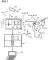
- a human-machine interface for exchanging at least one item of information between a user and a machine.
- the human-machine interface comprises at least one detector system according to the embodiments disclosed above and/or according to one or more of the embodiments disclosed in further detail below.
- the at least one beacon device is adapted to be at least one of directly or indirectly attached to the user or held by the user.
- the human-machine interface is designed to determine at least one position of the user by means of the detector system, wherein the human-machine interface is designed to assign to the position at least one item of information.
- an entertainment device for carrying out at least one entertainment function.
- the entertainment device comprises at least one human-machine interface according to the embodiment disclosed above and/or according to one or more of the embodiments disclosed in further detail below.
- the entertainment device is configured to enable at least one item of information to be input by a player by means of the human-machine interface.
- the entertainment device is further configured to vary the entertainment function in accordance with the information.
- a tracking system for tracking a position of at least one movable object.
- the tracking system comprises at least one detector system according to one or more of the embodiments referring to a detector system as disclosed above and/or as disclosed in further detail below.
- the tracking system further comprises at least one track controller.
- the track controller is adapted to track a series of positions of the object at specific points in time.
- a camera for imaging at least one object comprises at least one detector according to any one of the embodiments referring to a detector as disclosed above or as disclosed in further detail below.
- the present invention discloses a method for determining a position of at least one object by using a detector, such as a detector according to the present invention, such as according to one or more of the embodiments referring to a detector as disclosed above or as disclosed in further detail below. Still, other types of detectors may be used.
- the method comprises the following method steps, wherein the method steps may be performed in the given order or may be performed in a different order. Further, one or more additional method steps may be present which are not listed. Further, one, more than one or even all of the method steps may be performed repeatedly.
- the method may comprise using the detector according to the present invention, such as according to one or more of the embodiments given above or given in further detail below.
- a purpose of use selected from the group consisting of: a position measurement in traffic technology; an entertainment application; a security application; a surveillance application; a safety application; a human-machine interface application; a tracking application; a photography application; a use in combination with at least one time-of-flight detector; a use in combination with a structured light source; a use in combination with a stereo camera; a machine vision application; a robotics application; a quality control application; a manufacturing application; a use in combination with a structured illumination source; a use in combination with a stereo camera.
- the optical sensor may comprise one or more signal processing devices, such as one or more filters and/or analogue-digital-converters for processing and/or preprocessing the at least one signal.
- the one or more signal processing devices may fully or partially be integrated into the optical sensor and/or may fully or partially be embodied as independent software and/or hardware components.
- a center of the light spot may be determined, specifically by the evaluation device.
- the evaluation device generally may be adapted to determine at least one pixel having the highest illumination out of the pixels by comparing the signals of the pixels.
- the detector generally may be adapted to determine one or more pixels and/or an area or region of the matrix having the highest intensity of the illumination by the light beam. As an example, in this way, a center of the light spot generated by the light beam may be determined.
- the highest illumination and/or the information about the at least one area or region of highest illumination may be used in other ways, too.
- the highest illumination may also be used for determining whether the elimination still is within a predetermined or determinable measurement range, such as in order to determine whether the pixel signals still are within a linear range.
- An out of range detection may be implemented, in order to generate a warning in case a measurement range is exceeded and/or in order to apply technical means to bring back the pixel signals into the measurement range, such as by automatically applying one or more optical filters and/or software or hardware filters.
- the spot size may depend on the highest illumination within the light spot.
- the beam waist is defined as the radius of the light spot, extending from the center of illumination to a spot in which the intensity of the illumination has dropped down to a factor of 1/ e 2 .
- the threshold 1/ e 2 generally determines the borders of a light spot having a beam radius or beam waist w generated by a Gaussian light beam on the optical sensor.
- At least one optical sensor may be provided.
- the at least one optical sensor generally may be transparent or may be intransparent.
- the optical sensor may be transparent and adapted to transmit at least 10%, preferably at least 20% and, more preferably, at least 50% of the power of the light beam.
- at least one of the optical sensors is transparent.
- one of the major advantages of the present invention resides in the fact that conventional camera chips may be used as optical sensors, which, typically, are intransparent. In this case, a splitting of the beam path is typically preferable in case a plurality of optical sensors is used, in order to avoid the necessity of using transparent optical sensors.
- the optical sensors may have identical spectral sensitivities or may provide different spectral sensitivities.
- at least two of the optical sensors may have a differing spectral sensitivity.
- the term spectral sensitivity generally refers to the fact that the sensor signal of the optical sensor, for the same power of the light beam, may vary with the wavelength of the light beam.
- at least two of the optical sensors may differ with regard to their spectral properties. This embodiment generally may be achieved by using different types of optical filters and/or different types of absorbing materials for the optical sensors, such as different types of dyes or other absorbing materials.
- differing spectral properties of the optical sensors may be generated by other means implemented into the optical sensors and/or into the detector, such as by using one or more wavelength-selective elements, such as one or more filters (such as color filters) in front of the optical sensors and/or by using one or more prisms and/or by using one or more dichroitic mirrors.
- one or more wavelength-selective elements such as one or more filters (such as color filters) in front of the optical sensors and/or by using one or more prisms and/or by using one or more dichroitic mirrors.
- at least one of the optical sensors may comprise a wavelength-selective element such as a color filter, having a specific transmission or reflection characteristic, thereby generating differing spectral properties of the optical sensors.
- the evaluation device generally may be adapted to determine a color of the light beam by comparing sensor signals of the optical sensors having the differing spectral sensitivity.
- the expression "determine a color” generally refers to the step of generating at least one item of spectral information about the light beam.
- the at least one item of spectral information may be selected from the group consisting of a wavelength, specifically a peak wavelength; color coordinates, such as CIE coordinates.
- the determination of the color of the light beam may be performed in various ways which are generally known to the skilled person.
- the spectral sensitivities of the optical sensors may span a coordinate system in color space, and the signals provided by the optical sensors may provide a coordinate in this color space, as known to the skilled person for example from the way of determining CIE coordinates.
- the detector may comprise two, three or more optical sensors in a stack. Thereof, at least two, preferably at least three, of the optical sensors may have differing spectral sensitivities. Further, the evaluation device may be adapted to generate at least one item of color information for the light beam by evaluating the signals of the optical sensors having differing spectral sensitivities.
- the spectrally sensitive optical sensors may comprise at least one red sensitive optical sensor, the red sensitive optical sensor having a maximum absorption wavelength ⁇ r in a spectral range 600 nm ⁇ ⁇ r ⁇ 780 nm, wherein the spectrally sensitive optical sensors further comprise at least one green sensitive optical sensor, the green sensitive optical sensor having a maximum absorption wavelength ⁇ g in a spectral range 490 nm ⁇ ⁇ g ⁇ 600 nm, wherein the spectrally sensitive optical sensors further may comprise at least one blue sensitive optical sensor, the blue sensitive optical sensor having a maximum absorption wavelength ⁇ b in a spectral range 380 nm ⁇ ⁇ b ⁇ 490 nm.
- the red sensitive optical sensor, the green sensitive optical sensor and the blue sensitive optical sensor in this order or in a different order, may be the first optical sensors of the optical sensor stack, facing towards
- the evaluation device may be adapted to generate at least two color coordinates, preferably at least three color coordinates, wherein each of the color coordinates is determined by dividing a signal of one of the spectrally sensitive optical sensors by a normalization value.
- the normalization value may contain a sum of the signals of all spectrally sensitive optical sensors. Additionally or alternatively, the normalization value may contain a detector signal of a white detector.
- the at least one item of color information may contain the color coordinates.
- the at least one item of color information may, as an example, contain CIE coordinates.
- the detector may further comprise at least one white optical sensor, wherein the white detector may be adapted to absorb light in an absorption range of all spectrally sensitive detectors.
- the white optical sensor may have an absorption spectrum absorbing light all over the visible spectral range.
- the plurality of optical sensors may differ with regard to device setup and/or with regard to the materials used in the optical sensors.
- the optical sensors may differ with regard to their organic or inorganic in nature.
- the plurality of optical sensors may comprise one or more organic optical sensors, one or more inorganic optical sensors, one or more hybrid organic-inorganic optical sensors or an arbitrary combination of at least two of these optical sensors.
- the detector may consist of organic optical sensors only, may consist of inorganic optical sensors only or may consist of hybrid organic-inorganic optical sensors, only.
- the detector may comprise at least one organic optical sensor and at least one inorganic optical sensor or may comprise at least one organic optical sensor and at least one hybrid organic-inorganic optical sensor or may comprise at least one organic optical sensor and at least one hybrid organic-inorganic optical sensor.
- the detector may further comprise at least one transfer device.
- the transfer device preferably may be positioned in a light path, also referred to as a beam path, in between the object and the detector.
- a transfer device generally is an arbitrary optical element adapted to guide the light beam onto the optical sensor. The guiding may take place with unmodified properties of the light beam or may take place with imaging or modifying properties.
- the transfer device might have imaging properties and/or beam-shaping properties, i.e. might change a beam waist and/or a widening angle of the light beam and/or a shape of the cross-section of the light beam when the light beam passes the transfer device.
- the transfer device may comprise one or more elements selected from the group consisting of a lens and a mirror.
- the mirror may be selected from the group consisting of a planar mirror, a convex mirror and a concave mirror.
- one or more prisms may be comprised.
- one or more wavelength-selective elements may be comprised, such as one or more filters, specifically color filters, and/or one or more dichroitic mirrors.
- the transfer device may comprise one or more diaphragms, such as one or more pinhole diaphragms and/or iris diaphragms.
- the transfer device can for example comprise one or a plurality of mirrors and/or beam splitters and/or beam deflecting elements in order to influence a direction of the electromagnetic radiation.
- the transfer device can comprise one or a plurality of imaging elements which can have the effect of a converging lens and/or a diverging lens.
- the optional transfer device can have one or a plurality of lenses and/or one or a plurality of convex and/or concave mirrors.
- the transfer device can have at least one wavelength-selective element, for example at least one optical filter.
- the transfer device can be designed to impress a predefined beam profile on the electromagnetic radiation, for example, at the location of the sensor region and in particular the sensor area.
- the above-mentioned optional embodiments of the optional transfer device can, in principle, be realized individually or in any desired combination.
- the at least one transfer device may be positioned in front of the detector, i.e. on a side of the detector facing towards the object.
- At least one transversal coordinate of the object may be determined.
- the evaluation device may be adapted to provide at least one three-dimensional position of the object.
- a detector system for determining a position of at least one object.
- the detector system comprises at least one detector according to the present invention, such as at least one detector as disclosed in one or more of the embodiments described above and/or as disclosed in one or more of the embodiments disclosed in further detail below.
- the detector system further comprises at least one beacon device adapted to direct at least one light beam towards the detector.
- a beacon device generally refers to an arbitrary device adapted to direct at least one light beam towards the detector.
- the beacon device may fully or partially be embodied as an active beacon device, comprising at least one illumination source for generating the light beam. Additionally or alternatively, the beacon device may fully or partially be embodied as a passive beacon device comprising at least one reflective element adapted to reflect a primary light beam generated independently from the beacon device towards the detector.
- the beacon device is at least one of attachable to the object, holdable by the object and integratable into the object.
- the beacon device may be attached to the object by an arbitrary attachment means, such as one or more connecting elements.
- the object may be adapted to hold the beacon device, such as by one or more appropriate holding means.
- the beacon device may fully or partially be integrated into the object and, thus, may form part of the object or even may form the object.
- beacon device reference may be made to one or more of WO 2014/097181 A1 or US 2014/0291480 A1 or PCT/EP2014/078155 , the latter filed on December 17, 2014. Still, other embodiments are feasible.
- the beacon device may fully or partially be embodied as an active beacon device and may comprise at least one illumination source.
- the beacon device may comprise a generally arbitrary illumination source, such as an illumination source selected from the group consisting of a light-emitting diode (LED), a light bulb, an incandescent lamp and a fluorescent lamp.
- LED light-emitting diode
- the beacon device may comprise a generally arbitrary illumination source, such as an illumination source selected from the group consisting of a light-emitting diode (LED), a light bulb, an incandescent lamp and a fluorescent lamp.
- LED light-emitting diode
- the beacon device may fully or partially be embodied as a passive beacon device and may comprise at least one reflective device adapted to reflect a primary light beam generated by an illumination source independent from the object.
- the beacon device may be adapted to reflect a primary light beam towards the detector.
- the detector system may comprise one, two, three or more beacon devices.
- the object in case the object is a rigid object which, at least on a microscope scale, thus not change its shape, preferably, at least two beacon devices may be used.
- the object In case the object is fully or partially flexible or is adapted to fully or partially change its shape, preferably, three or more beacon devices may be used.
- the number of beacon devices may be adapted to the degree of flexibility of the object.
- the detector system comprises at least three beacon devices.
- the object generally may be a living or non-living object.
- the detector system even may comprise the at least one object, the object thereby forming part of the detector system.
- the object may move independently from the detector, in at least one spatial dimension.
- the object generally may be an arbitrary object.
- the object may be a rigid object.
- Other embodiments are feasible, such as embodiments in which the object is a non-rigid object or an object which may change its shape.
- the present invention may specifically be used for tracking positions and/or motions of a person, such as for the purpose of controlling machines, gaming or simulation of sports.
- the object may be selected from the group consisting of: an article of sports equipment, preferably an article selected from the group consisting of a racket, a club, a bat; an article of clothing; a hat; a shoe.
- the human-machine interface for exchanging at least one item of information between a user and a machine.
- the human-machine interface comprises at least one detector system according to the present invention, such as to one or more of the embodiments disclosed above and/or according to one or more of the embodiments disclosed in further detail below.
- the beacon devices are adapted to be at least one of directly or indirectly attached to the user and held by the user.
- the human-machine interface is designed to determine at least one position of the user by means of the detector system.
- the human-machine interface further is designed to assign to the position at least one item of information.
- an entertainment device for carrying out at least one entertainment function.
- the entertainment device comprises at least one human-machine interface according to the present invention.
- the entertainment device further is designed to enable at least one item of information to be input by a player by means of the human-machine interface.
- the entertainment device further is designed to vary the entertainment function in accordance with the information.
- the tracking system for tracking a position of at least one movable object.
- the tracking system comprises at least one detector system according to the present invention, such as to one or more of the embodiments disclosed above and/or according to one or more of the embodiments disclosed in further detail below.
- the tracking system further comprises at least one track controller, wherein the track controller is adapted to track a series of positions of the object at specific points in time.
- the devices according to the present invention may be applied in various fields of uses.
- the detector may be applied for a purpose of use, selected from the group consisting of: a position measurement in traffic technology; an entertainment application; a security application; a human-machine interface application; a tracking application; a photography application; a mapping application for generating maps of at least one space, such as at least one space selected from the group of a room, a building and a street; a mobile application; a webcam; an audio device; a dolby surround audio system; a computer peripheral device; a gaming application; a camera or video application; a security application; a surveillance application; an automotive application; a transport application; a medical application; a sports' application; a machine vision application; a vehicle application; an airplane application; a ship application; a spacecraft application; a building application; a construction application; a cartography application; a manufacturing application; a use in combination with at least one time-of-flight
- applications in local and/or global positioning systems may be named, especially landmark-based positioning and/or navigation, specifically for use in cars or other vehicles (such as trains, motorcycles, bicycles, trucks for cargo transportation), robots or for use by pedestrians.
- indoor positioning systems may be named as potential applications, such as for household applications and/or for robots used in manufacturing technology.
- the devices according to the present invention may be used in mobile phones, tablet computers, laptops, smart panels or other stationary or mobile or wearable computer or communication applications.
- the devices according to the present invention may be combined with at least one active light source, such as a light source emitting light in the visible range or infrared spectral range, in order to enhance performance.
- the devices according to the present invention may be used as cameras and/or sensors, such as in combination with mobile software for scanning environment, objects and living beings.
- the devices according to the present invention may even be combined with 2D cameras, such as conventional cameras, in order to increase imaging effects.
- the devices according to the present invention may further be used for surveillance and/or for recording purposes or as input devices to control mobile devices, especially in combination with voice and/or gesture recognition.
- the devices according to the present invention acting as human-machine interfaces also referred to as input devices, may be used in mobile applications, such as for controlling other electronic devices or components via the mobile device, such as the mobile phone.
- the mobile application including at least one device according to the present invention may be used for controlling a television set, a game console, a music player or music device or other entertainment devices.
- the devices according to the present invention may be used in webcams or other peripheral devices for computing applications.
- the devices according to the present invention may be used in combination with software for imaging, recording, surveillance, scanning or motion detection.
- the devices according to the present invention are particularly useful for giving commands by facial expressions and/or body expressions.
- the devices according to the present invention can be combined with other input generating devices like e.g. mouse, keyboard, touchpad, microphone etc.
- the devices according to the present invention may be used in applications for gaming, such as by using a webcam.
- the devices according to the present invention may be used in virtual training applications and/or video conferences.
- devices according to the present invention may be used to recognize or track hands, arms, or objects used in a virtual or augmented reality application, especially when wearing head mounted displays.
- the devices according to the present invention may be used in mobile audio devices, television devices and gaming devices, as partially explained above.
- the devices according to the present invention may be used as controls or control devices for electronic devices, entertainment devices or the like.
- the devices according to the present invention may be used for eye detection or eye tracking, such as in 2D- and 3D-display techniques, especially with transparent displays for augmented reality applications and/or for recognizing whether a display is being looked at and/or from which perspective a display is being looked at.
- devices according to the present invention may be used to explore a room, boundaries, obstacles, in connection with a virtual or augmented reality application, especially when wearing a head-mounted display.
- the devices according to the present invention may be used in or as digital cameras such as DSC cameras and/or in or as reflex cameras such as SLR cameras.
- digital cameras such as DSC cameras
- reflex cameras such as SLR cameras
- the devices according to the present invention may be used for security or surveillance applications.
- at least one device according to the present invention can be combined with one or more digital and/or analogue electronics that will give a signal if an object is within or outside a predetermined area (e.g. for surveillance applications in banks or museums).
- the devices according to the present invention may be used for optical encryption. Detection by using at least one device according to the present invention can be combined with other detection devices to complement wavelengths, such as with IR, x-ray, UV-VIS, radar or ultrasound detectors.
- the devices according to the present invention may further be combined with an active infrared light source to allow detection in low light surroundings.
- the devices according to the present invention are generally advantageous as compared to active detector systems, specifically since the devices according to the present invention avoid actively sending signals which may be detected by third parties, as is the case e.g. in radar applications, ultrasound applications, LIDAR or similar active detector devices.
- the devices according to the present invention may be used for an unrecognized and undetectable tracking of moving objects. Additionally, the devices according to the present invention generally are less prone to manipulations and irritations as compared to conventional devices.
- the devices according to the present invention generally may be used for facial, body and person recognition and identification.
- the devices according to the present invention may be combined with other detection means for identification or personalization purposes such as passwords, finger prints, iris detection, voice recognition or other means.
- the devices according to the present invention may be used in security devices and other personalized applications.
- the devices according to the present invention may be used as 3D barcode readers for product identification.
- the devices according to the present invention generally can be used for surveillance and monitoring of spaces and areas.
- the devices according to the present invention may be used for surveying and monitoring spaces and areas and, as an example, for triggering or executing alarms in case prohibited areas are violated.
- the devices according to the present invention may be used for surveillance purposes in building surveillance or museums, optionally in combination with other types of sensors, such as in combination with motion or heat sensors, in combination with image intensifiers or image enhancement devices and/or photomultipliers.
- the devices according to the present invention may be used in public spaces or crowded spaces to detect potentially hazardous activities such as commitment of crimes such as theft in a parking lot or unattended objects such as unattended baggage in an airport.
- the devices according to the present invention may advantageously be applied in camera applications such as video and camcorder applications.
- the devices according to the present invention may be used for motion capture and 3D-movie recording.
- the devices according to the present invention generally provide a large number of advantages over conventional optical devices.
- the devices according to the present invention generally require a lower complexity with regard to optical components.
- the number of lenses may be reduced as compared to conventional optical devices, such as by providing the devices according to the present invention having one lens only. Due to the reduced complexity, very compact devices are possible, such as for mobile use.
- Conventional optical systems having two or more lenses with high quality generally are voluminous, such as due to the general need for voluminous beam-splitters.
- the devices according to the present invention generally may be used for focus/autofocus devices, such as autofocus cameras.
- the devices according to the present invention may also be used in optical microscopy, especially in confocal microscopy.
- the devices according to the present invention generally are applicable in the technical field of automotive technology and transport technology.
- the devices according to the present invention may be used as distance and surveillance sensors, such as for adaptive cruise control, emergency brake assist, lane departure warning, surround view, blind spot detection, rear cross traffic alert, and other automotive and traffic applications.
- the devices according to the present invention can also be used for velocity and/or acceleration measurements, such as by analyzing a first and second time-derivative of position information gained by using the detector according to the present invention.
- This feature generally may be applicable in automotive technology, transportation technology or general traffic technology. Applications in other fields of technology are feasible.
- a specific application in an indoor positioning system may be the detection of positioning of passengers in transportation, more specifically to electronically control the use of safety systems such as airbags. The use of an airbag may be prevented in case the passenger is located as such, that the use of an airbag will cause a severe injury.
- the devices according to the present invention may be used as standalone devices or in combination with other sensor devices, such as in combination with radar and/or ultrasonic devices.
- the devices according to the present invention may be used for autonomous driving and safety issues.
- the devices according to the present invention may be used in combination with infrared sensors, radar sensors, which are sonic sensors, two-dimensional cameras or other types of sensors.
- the generally passive nature of the devices according to the present invention is advantageous.
- the devices according to the present invention specifically may be used in combination with recognition software, such as standard image recognition software.
- signals and data as provided by the devices according to the present invention typically are readily processable and, therefore, generally require lower calculation power than established stereovision systems such as LIDAR.
- the devices according to the present invention such as cameras may be placed at virtually any place in a vehicle, such as on a window screen, on a front hood, on bumpers, on lights, on mirrors or other places and the like.
- Various detectors according to the present invention such as one or more detectors based on the effect disclosed within the present invention can be combined, such as in order to allow autonomously driving vehicles or in order to increase the performance of active safety concepts.
- various devices according to the present invention may be combined with one or more other devices according to the present invention and/or conventional sensors, such as in the windows like rear window, side window or front window, on the bumpers or on the lights.
- a combination of at least one device according to the present invention such as at least one detector according to the present invention with one or more rain detection sensors is also possible. This is due to the fact that the devices according to the present invention generally are advantageous over conventional sensor techniques such as radar, specifically during heavy rain.
- a combination of at least one device according to the present invention with at least one conventional sensing technique such as radar may allow for a software to pick the right combination of signals according to the weather conditions.
- the devices according to the present invention generally may be used as break assist and/or parking assist and/or for speed measurements.
- Speed measurements can be integrated in the vehicle or may be used outside the vehicle, such as in order to measure the speed of other cars in traffic control. Further, the devices according to the present invention may be used for detecting free parking spaces in parking lots.
- the devices according to the present invention may be used is the fields of medical systems and sports.
- surgery robotics e.g. for use in endoscopes
- the devices according to the present invention may require a low volume only and may be integrated into other devices.
- the devices according to the present invention having one lens, at most, may be used for capturing 3D information in medical devices such as in endoscopes.
- the devices according to the present invention may be combined with an appropriate monitoring software, in order to enable tracking and analysis of movements.
- the devices according to the present invention may be used in 3D-body scanning.
- Body scanning may be applied in a medical context, such as in dental surgery, plastic surgery, bariatric surgery, or cosmetic plastic surgery, or it may be applied in the context of medical diagnosis such as in the diagnosis of myofascial pain syndrome, cancer, body dysmorphic disorder, or further diseases. Body scanning may further be applied in the field of sports to assess ergonomic use or fit of sports equipment.
- Body scanning may further be used in the context of clothing, such as to determine a suitable size and fitting of clothes.
- This technology may be used in the context of tailor-made clothes or in the context of ordering clothes or shoes from the internet or at a self-service shopping device such as a micro kiosk device or customer concierge device.
- Body scanning in the context of clothing is especially important for scanning fully dressed customers.
- the devices according to the present invention may be used in the context of people counting systems, such as to count the number of people in an elevator, a train, a bus, a car, or a plane, or to count the number of people passing a hallway, a door, an aisle, a retail store, a stadium, an entertainment venue, a museum, a library, a public location, a cinema, a theater, or the like.
- the 3D-function in the people counting system may be used to obtain or estimate further information about the people that are counted such as height, weight, age, physical fitness, or the like. This information may be used for business intelligence metrics, and/or for further optimizing the locality where people may be counted to make it more attractive or safe.
- the devices according to the present invention in the context of people counting may be used to recognize returning customers or cross shoppers, to assess shopping behavior, to assess the percentage of visitors that make purchases, to optimize staff shifts, or to monitor the costs of a shopping mall per visitor.
- people counting systems may be used for anthropometric surveys.
- the devices according to the present invention may be used in public transportation systems for automatically charging passengers depending on the length of transport.
- the devices according to the present invention may be used in playgrounds for children, to recognize injured children or children engaged in dangerous activities, to allow additional interaction with playground toys, to ensure safe use of playground toys or the like.
- the devices according to the present invention may be used in construction tools, such as a range meter that determines the distance to an object or to a wall, to assess whether a surface is planar, to align or objects or place objects in an ordered manner, or in inspection cameras for use in construction environments or the like.
- construction tools such as a range meter that determines the distance to an object or to a wall, to assess whether a surface is planar, to align or objects or place objects in an ordered manner, or in inspection cameras for use in construction environments or the like.
- the devices according to the present invention may be applied in the field of sports and exercising, such as for training, remote instructions or competition purposes.
- the devices according to the present invention may be applied in the fields of dancing, aerobic, football, soccer, basketball, baseball, cricket, hockey, track and field, swimming, polo, handball, volleyball, rugby, sumo, judo, fencing, boxing, golf, car racing, laser tag, battlefield simulation etc.
- the devices according to the present invention can be used to detect the position of a ball, a bat, a sword, motions, etc., both in sports and in games, such as to monitor the game, support the referee or for judgment, specifically automatic judgment, of specific situations in sports, such as for judging whether a point or a goal actually was made.
- the devices according to the present invention may be used in the field of auto racing or car driver trainings or car safety trainings or the like to determine the position of a car or the track of a car, or the deviation from a previous track or an ideal track or the like.
- the devices according to the present invention may further be used to support a practice of musical instruments, in particular remote lessons, for example lessons of string instruments, such as fiddles, violins, violas, celli, basses, harps, guitars, banjos, or ukuleles, keyboard instruments, such as pianos, organs, keyboards, harpsichords, harmoniums, or accordions, and/or percussion instruments, such as drums, timpani, marimbas, xylophones, vibraphones, bongos, congas, timbales, djembes or tablas.
- string instruments such as fiddles, violins, violas, celli, basses, harps, guitars, banjos, or ukuleles
- keyboard instruments such as pianos, organs, keyboards, harpsichords, harmoniums, or accordions
- percussion instruments such as drums, timpani, marimbas, xylo
- the devices according to the present invention further may be used in rehabilitation and physiotherapy, in order to encourage training and/or in order to survey and correct movements. Therein, the devices according to the present invention may also be applied for distance diagnostics.
- the devices according to the present invention may be applied in the field of machine vision.
- one or more of the devices according to the present invention may be used e.g. as a passive controlling unit for autonomous driving and or working of robots.
- the devices according to the present invention may allow for autonomous movement and/or autonomous detection of failures in parts.
- the devices according to the present invention may also be used for manufacturing and safety surveillance, such as in order to avoid accidents including but not limited to collisions between robots, production parts and living beings.
- robotics the safe and direct interaction of humans and robots is often an issue, as robots may severely injure humans when they are not recognized.
- Devices according to the present invention may help robots to position objects and humans better and faster and allow a safe interaction.
- the devices according to the present invention may be advantageous over active devices and/or may be used complementary to existing solutions like radar, ultrasound, 2D cameras, IR detection etc.
- One particular advantage of the devices according to the present invention is the low likelihood of signal interference. Therefore multiple sensors can work at the same time in the same environment, without the risk of signal interference.
- the devices according to the present invention generally may be useful in highly automated production environments like e.g. but not limited to automotive, mining, steel, etc.
- the devices according to the present invention can also be used for quality control in production, e.g. in combination with other sensors like 2-D imaging, radar, ultrasound, IR etc., such as for quality control or other purposes.
- the devices according to the present invention may be used for assessment of surface quality, such as for surveying the surface evenness of a product or the adherence to specified dimensions, from the range of micrometers to the range of meters. Other quality control applications are feasible.
- the devices according to the present invention are especially useful for processing natural products such as food or wood, with a complex 3-dimensional structure to avoid large amounts of waste material. Further, devices according to the present invention may be used to monitor the filling level of tanks, silos etc.
- devices according to the present invention may be used to inspect complex products for missing parts, incomplete parts, loose parts, low quality parts, or the like, such as in automatic optical inspection, such as of printed circuit boards, inspection of assemblies or sub-assemblies, verification of engineered components, engine part inspections, wood quality inspection, label inspections, inspection of medical devices, inspection of product orientations, packaging inspections, food pack inspections, or the like.
- automatic optical inspection such as of printed circuit boards, inspection of assemblies or sub-assemblies, verification of engineered components, engine part inspections, wood quality inspection, label inspections, inspection of medical devices, inspection of product orientations, packaging inspections, food pack inspections, or the like.
- the devices according to the present invention may be used in vehicles, trains, airplanes, ships, spacecraft and other traffic applications.
- passive tracking systems for aircraft, vehicles and the like may be named.
- the use of at least one device according to the present invention, such as at least one detector according to the present invention, for monitoring the speed and/or the direction of moving objects is feasible.
- the tracking of fast moving objects on land, sea and in the air including space may be named.
- the at least one device according to the present invention such as the at least one detector according to the present invention, specifically may be mounted on a still-standing and/or on a moving device.
- An output signal of the at least one device according to the present invention can be combined e.g.
- the devices according to the present invention generally are useful and advantageous due to the low calculation power required, the instant response and due to the passive nature of the detection system which generally is more difficult to detect and to disturb as compared to active systems, like e.g. radar.
- the devices according to the present invention are particularly useful but not limited to e.g. speed control and air traffic control devices. Further, the devices according to the present invention may be used in automated tolling systems for road charges.
- the devices according to the present invention generally may be used in passive applications. Passive applications include guidance for ships in harbors or in dangerous areas, and for aircraft at landing or starting. Wherein, fixed, known active targets may be used for precise guidance. The same can be used for vehicles driving on dangerous but well defined routes, such as mining vehicles. Further, the devices according to the present invention may be used to detect rapidly approaching objects, such as cars, trains, flying objects, animals, or the like. Further, the devices according to the present invention can be used for detecting velocities or accelerations of objects, or to predict the movement of an object by tracking one or more of its position, speed, and/or acceleration depending on time.
- the devices according to the present invention may be used in the field of gaming.
- the devices according to the present invention can be passive for use with multiple objects of the same or of different size, color, shape, etc., such as for movement detection in combination with software that incorporates the movement into its content.
- applications are feasible in implementing movements into graphical output.
- applications of the devices according to the present invention for giving commands are feasible, such as by using one or more of the devices according to the present invention for gesture or facial recognition.
- the devices according to the present invention may be combined with an active system in order to work under e.g. low light conditions or in other situations in which enhancement of the surrounding conditions is required.
- a combination of one or more devices according to the present invention with one or more IR or VIS light sources is possible.
- a combination of a detector according to the present invention with special devices is also possible, which can be distinguished easily by the system and its software, e.g. and not limited to, a special color, shape, relative position to other devices, speed of movement, light, frequency used to modulate light sources on the device, surface properties, material used, reflection properties, transparency degree, absorption characteristics, etc.
- the device can, amongst other possibilities, resemble a stick, a racquet, a club, a gun, a knife, a wheel, a ring, a steering wheel, a bottle, a ball, a glass, a vase, a spoon, a fork, a cube, a dice, a figure, a puppet, a teddy, a beaker, a pedal, a switch, a glove, jewelry, a musical instrument or an auxiliary device for playing a musical instrument, such as a plectrum, a drumstick or the like.
- Other options are feasible.
- the devices according to the present invention may be used to detect and or track objects that emit light by themselves, such as due to high temperature or further light emission processes.
- the light emitting part may be an exhaust stream or the like.
- the devices according to the present invention may be used to track reflecting objects and analyze the rotation or orientation of these objects.
- the devices according to the present invention generally may be used in the field of building, construction and cartography.
- one or more devices according to the present invention may be used in order to measure and/or monitor environmental areas, e.g. countryside or buildings.
- one or more devices according to the present invention may be combined with other methods and devices or can be used solely in order to monitor progress and accuracy of building projects, changing objects, houses, etc.
- the devices according to the present invention can be used for generating three-dimensional models of scanned environments, in order to construct maps of rooms, streets, houses, communities or landscapes, both from ground or from air. Potential fields of application may be construction, cartography, real estate management, land surveying or the like.
- the devices according to the present invention may be used in multicopters to monitor buildings, agricultural production environments such as fields, production plants, or landscapes, to support rescue operations, or to find or monitor one or more persons or animals, or the like.
- the devices according to the present invention may be used within an interconnecting network of home appliances such as CHAIN (Cedec Home Appliances Interoperating Network) to interconnect, automate, and control basic appliance-related services in a home, e.g. energy or load management, remote diagnostics, pet related appliances, child related appliances, child surveillance, appliances related surveillance, support or service to elderly or ill persons, home security and/or surveillance, remote control of appliance operation, and automatic maintenance support.
- the devices according to the present invention may be used in heating or cooling systems such as an air-conditioning system, to locate which part of the room should be brought to a certain temperature or humidity, especially depending on the location of one or more persons.
- the devices according to the present invention may be used in domestic robots, such as service or autonomous robots which may be used for household chores.
- the devices according to the present invention may be used for a number of different purposes, such as to avoid collisions or to map the environment, but also to identify a user, to personalize the robots performance for a given user, for security purposes, or for gesture or facial recognition.
- the devices according to the present invention may be used in robotic vacuum cleaners, floor-washing robots, dry-sweeping robots, ironing robots for ironing clothes, animal litter robots, such as cat litter robots, security robots that detect intruders, robotic lawn mowers, automated pool cleaners, rain gutter cleaning robots, window washing robots, toy robots, telepresence robots, social robots providing company to less mobile people, or robots translating and speech to sign language or sign language to speech.
- household robots with the devices according to the present invention may be used for picking up objects, transporting objects, and interacting with the objects and the user in a safe way.
- the devices according to the present invention may be used in robots operating with hazardous materials or objects or in dangerous environments.
- the devices according to the present invention may be used in robots or unmanned remote-controlled vehicles to operate with hazardous materials such as chemicals or radioactive materials especially after disasters, or with other hazardous or potentially hazardous objects such as mines, unexploded arms, or the like, or to operate in or to investigate insecure environments such as near burning objects or post disaster areas.
- the devices according to the present invention may be used in household, mobile or entertainment devices, such as a refrigerator, a microwave, a washing machine, a window blind or shutter, a household alarm, an air condition devices, a heating device, a television, an audio device, a smart watch, a mobile phone, a phone, a dishwasher, a stove or the like, to detect the presence of a person, to monitor the contents or function of the device, or to interact with the person and/or share information about the person with further household, mobile or entertainment devices.
- household, mobile or entertainment devices such as a refrigerator, a microwave, a washing machine, a window blind or shutter, a household alarm, an air condition devices, a heating device, a television, an audio device, a smart watch, a mobile phone, a phone, a dishwasher, a stove or the like, to detect the presence of a person, to monitor the contents or function of the device, or to interact with the person and/or share information about the person with further household, mobile or entertainment devices.
- the devices according to the present invention may further be used in agriculture, for example to detect and sort out vermin, weeds, and/or infected crop plants, fully or in parts, wherein crop plants may be infected by fungus or insects. Further, for harvesting crops, the devices according to the present invention may be used to detect animals, such as deer, which may otherwise be harmed by harvesting devices. Further, the devices according to the present invention may be used to monitor the growth of plants in a field or greenhouse, in particular to adjust the amount of water or fertilizer or crop protection products for a given region in the field or greenhouse or even for a given plant. Further, in agricultural biotechnology, the devices according to the present invention may be used to monitor the size and shape of plants.
- the devices according to the present invention may be combined with sensors to detect chemicals or pollutants, electronic nose chips, microbe sensor chips to detect bacteria or viruses or the like, Geiger counters, tactile sensors, heat sensors, or the like.
- This may for example be used in constructing smart robots which are configured for handling dangerous or difficult tasks, such as in treating highly infectious patients, handling or removing highly dangerous substances, cleaning highly polluted areas, such as highly radioactive areas or chemical spills, or for pest control in agriculture.
- One or more devices according to the present invention can further be used for scanning of objects, such as in combination with CAD or similar software, such as for additive manufacturing and/or 3D printing. Therein, use may be made of the high dimensional accuracy of the devices according to the present invention, e.g. in x-, y- or z- direction or in any arbitrary combination of these directions, such as simultaneously. Further, the devices according to the present invention may be used in inspections and maintenance, such as pipeline inspection gauges.
- the devices according to the present invention may be used to work with objects of a badly defined shape such as naturally grown objects, such as sorting vegetables or other natural products by shape or size or cutting products such as meat or objects that are manufactured with a precision that is lower than the precision needed for a processing step.
- objects of a badly defined shape such as naturally grown objects, such as sorting vegetables or other natural products by shape or size or cutting products such as meat or objects that are manufactured with a precision that is lower than the precision needed for a processing step.
- the devices according to the present invention may be used in local navigation systems to allow autonomously or partially autonomously moving vehicles or multicopters or the like through an indoor or outdoor space.
- a non-limiting example may comprise vehicles moving through an automated storage for picking up objects and placing them at a different location.
- Indoor navigation may further be used in shopping malls, retail stores, museums, airports, or train stations, to track the location of mobile goods, mobile devices, baggage, customers or employees, or to supply users with a location specific information, such as the current position on a map, or information on goods sold, or the like.
- the devices according to the present invention may be used to ensure safe driving of motorcycles such as driving assistance for motorcycles by monitoring speed, inclination, upcoming obstacles, unevenness of the road, or curves or the like. Further, the devices according to the present invention may be used in trains or trams to avoid collisions.
- the devices according to the present invention may be used in handheld devices, such as for scanning packagings or parcels to optimize a logistics process. Further, the devices according to the present invention may be used in further handheld devices such as personal shopping devices, RFID-readers, handheld devices for use in hospitals or health environments such as for medical use or to obtain, exchange or record patient or patient health related information, smart badges for retail or health environments, or the like.
- the devices according to the present invention may further be used in manufacturing, quality control or identification applications, such as in product identification or size identification (such as for finding an optimal place or package, for reducing waste etc.). Further, the devices according to the present invention may be used in logistics applications. Thus, the devices according to the present invention may be used for optimized loading or packing containers or vehicles. Further, the devices according to the present invention may be used for monitoring or controlling of surface damages in the field of manufacturing, for monitoring or controlling rental objects such as rental vehicles, and/or for insurance applications, such as for assessment of damages. Further, the devices according to the present invention may be used for identifying a size of material, object or tools, such as for optimal material handling, especially in combination with robots.
- the devices according to the present invention may be used for process control in production, e.g. for observing filling level of tanks. Further, the devices according to the present invention may be used for maintenance of production assets like, but not limited to, tanks, pipes, reactors, tools etc. Further, the devices according to the present invention may be used for analyzing 3D-quality marks. Further, the devices according to the present invention may be used in manufacturing tailor-made goods such as tooth inlays, dental braces, prosthesis, clothes or the like. The devices according to the present invention may also be combined with one or more 3D-printers for rapid prototyping, 3D-copying or the like. Further, the devices according to the present invention may be used for detecting the shape of one or more articles, such as for anti-product piracy and for anti-counterfeiting purposes.
- the present application may be applied in the field of photography.
- the detector may be part of a photographic device, specifically of a digital camera.
- the detector may be used for 3D photography, specifically for digital 3D photography.
- the detector may form a digital 3D camera or may be part of a digital 3D camera.
- photography generally refers to the technology of acquiring image information of at least one object.
- a camera generally is a device adapted for performing photography.
- digital photography generally refers to the technology of acquiring image information of at least one object by using a plurality of light-sensitive elements adapted to generate electrical signals indicating an intensity and/or color of illumination, preferably digital electrical signals.
- the term 3D photography generally refers to the technology of acquiring image information of at least one object in three spatial dimensions.
- a 3D camera is a device adapted for performing 3D photography.
- the camera generally may be adapted for acquiring a single image, such as a single 3D image, or may be adapted for acquiring a plurality of images, such as a sequence of images.
- the camera may also be a video camera adapted for video applications, such as for acquiring digital video sequences.
- the present invention further refers to a camera, specifically a digital camera, more specifically a 3D camera or digital 3D camera, for imaging at least one object.
- imaging generally refers to acquiring image information of at least one object.
- the camera comprises at least one detector according to the present invention.
- the camera as outlined above, may be adapted for acquiring a single image or for acquiring a plurality of images, such as image sequence, preferably for acquiring digital video sequences.
- the camera may be or may comprise a video camera. In the latter case, the camera preferably comprises a data memory for storing the image sequence.
- the expression "position” generally refers to at least one item of information regarding one or more of an absolute position and an orientation of one or more points of the object.
- the position may be determined in a coordinate system of the detector, such as in a Cartesian coordinate system. Additionally or alternatively, however, other types of coordinate systems may be used, such as polar coordinate systems and/or spherical coordinate systems.
- the present invention preferably may be applied in the field of human-machine interfaces, in the field of sports and/or in the field of computer games.
- the object may be selected from the group consisting of: an article of sports equipment, preferably an article selected from the group consisting of a racket, a club, a bat; an article of clothing; a hat; a shoe.
- Other embodiments are feasible.
- the object generally may be an arbitrary object, chosen from a living object and a non-living object.
- the at least one object may comprise one or more articles and/or one or more parts of an article.
- the object may be or may comprise one or more living beings and/or one or more parts thereof, such as one or more body parts of a human being, e.g. a user, and/or an animal.
- the detector may constitute a coordinate system in which an optical axis of the detector forms the z-axis and in which, additionally, an x-axis and a y-axis may be provided which are perpendicular to the z-axis and which are perpendicular to each other.
- the detector and/or a part of the detector may rest at a specific point in this coordinate system, such as at the origin of this coordinate system.
- a direction parallel or antiparallel to the z-axis may be regarded as a longitudinal direction, and a coordinate along the z-axis may be considered a longitudinal coordinate.
- An arbitrary direction perpendicular to the longitudinal direction may be considered a transversal direction, and an x- and/or y-coordinate may be considered a transversal coordinate.
- a polar coordinate system may be used in which the optical axis forms a z-axis and in which a distance from the z-axis and a polar angle may be used as additional coordinates.
- a direction parallel or antiparallel to the z-axis may be considered a longitudinal direction
- a coordinate along the z-axis may be considered a longitudinal coordinate.
- Any direction perpendicular to the z-axis may be considered a transversal direction, and the polar coordinate and/or the polar angle may be considered a transversal coordinate.
- the detector may be a device configured for providing at least one item of information on the position of the at least one object and/or a part thereof.
- the position may refer to an item of information fully describing the position of the object or a part thereof, preferably in the coordinate system of the detector, or may refer to a partial information, which only partially describes the position.
- the detector generally may be a device adapted for detecting light beams, such as the light beams propagating from the beacon devices towards the detector.
- the evaluation device and the detector may fully or partially be integrated into a single device.
- the evaluation device also may form part of the detector.
- the evaluation device and the detector may fully or partially be embodied as separate devices.
- the detector may comprise further components.
- the detector may be a stationary device or a mobile device. Further, the detector may be a stand-alone device or may form part of another device, such as a computer, a vehicle or any other device. Further, the detector may be a hand-held device. Other embodiments of the detector are feasible.
- the detector specifically may be used to record a light-field behind a lens or lens system of the detector, comparable to a plenoptic or light-field camera.
- the detector may be embodied as a light-field camera adapted for acquiring images in multiple focal planes, such as simultaneously.
- the term light-field generally refers to the spatial light propagation of light inside the detector such as inside camera.
- the detector according to the present invention specifically having a stack of optical sensors, may have the capability of directly recording a light-field within the detector or camera, such as behind a lens.
- the plurality of pixelated sensors may record images at different distances from the lens.
- the propagation direction, focus points, and spread of the light behind the lens can be modeled.
- images at various distances to the lens can be extracted, the depth of field can be optimized, pictures that are in focus at various distances can be extracted, or distances of objects can be calculated. Further information may be extracted.
- the light-field may be recorded in terms of beam parameters for one or more light beams of a scene captured by the detector.
- two or more beam parameters may be recorded, such as one or more Gaussian beam parameters, e.g. a beam waist, a minimum beam waist as a focal point, a Rayleigh length, or other beam parameters.
- Gaussian beam parameters e.g. a beam waist, a minimum beam waist as a focal point, a Rayleigh length, or other beam parameters.
- beam parameters may be chosen accordingly.
- This knowledge of light propagation allows for slightly modifying the observer position after recording an image stack using image processing techniques.
- an object may be hidden behind another object and is not visible. However, if the light scattered by the hidden object reaches the lens and through the lens one or more of the sensors, the object may be made visible, by changing the distance to the lens and/or the image plane relative to the optical axis, or even using non-planar image planes.
- the change of the observer position may be compared to looking at a hologram, in which changing the observer position slightly changes the image.
- the knowledge of light propagation inside the detector may further allow for storing the image information in a more compact way as compared to conventional technology of storing each image recorded by each individual optical sensor.
- the memory demand for storing all images of each optical sensor typically scales with the number of sensors times the number of pixels.
- the memory demand of the light propagation scales with the number of modeled light beams times the number of parameters per light beam.
- Typical model functions for light beams may be Gaussians, Lorentzians, Bessel functions, especially spherical Bessel functions, other functions typically used for describing diffraction effects in physics, or typical spread functions used in depth from defocus techniques such as point spread functions, line spread functions or edge spread functions.
- Optical instruments often become expensive and challenging in construction, when lens errors need to be corrected. These are especially problematic in microscopes and telescopes.
- a typical lens error is that rays of varying distance to the optical axis are distorted differently (spherical aberration).
- varying the focus may occur from differing temperatures in the atmosphere.
- Static errors such as spherical aberration or further errors from production may be corrected by determining the errors in a calibration step and then using a fixed image processing such as fixed set of pixels and sensor, or more involved processing techniques using light propagation information.
- the lens errors may be corrected by using the light propagation behind the lens, calculating extended depth of field images, using depth from focus techniques, and others.
- the detector according to the present invention may further allow for color detection.
- the single stacks may have pixels that have different absorption properties, equal or similar to the so-called Bayer pattern, and color information may be obtained by interpolation techniques.
- a further method is to use sensors of alternating color, wherein different sensors in the stack may record different colors. In a Bayer pattern, color may be interpolated between same-color pixels. In a stack of sensors, the image information such as color and brightness, etc., can also be obtained by interpolation techniques.
- the evaluation device may be or may comprise one or more integrated circuits, such as one or more application-specific integrated circuits (ASICs), and/or one or more data processing devices, such as one or more computers, preferably one or more microcomputers and/or microcontrollers. Additional components may be comprised, such as one or more preprocessing devices and/or data acquisition devices, such as one or more devices for receiving and/or preprocessing of the sensor signals, such as one or more AD-converters and/or one or more filters. Further, the evaluation device may comprise one or more measurement devices, such as one or more measurement devices for measuring electrical currents and/or electrical voltages. Thus, as an example, the evaluation device may comprise one or more measurement devices for measuring electrical currents through and/or electrical voltages of the pixels. Further, the evaluation device may comprise one or more data storage devices. Further, the evaluation device may comprise one or more interfaces, such as one or more wireless interfaces and/or one or more wire-bound interfaces.
- ASICs application-specific integrated circuits
- data processing devices such as one
- the at least one evaluation device may be adapted to perform at least one computer program, such as at least one computer program adapted for performing or supporting one or more or even all of the method steps of the method according to the present invention.
- at least one computer program such as at least one computer program adapted for performing or supporting one or more or even all of the method steps of the method according to the present invention.
- one or more algorithms may be implemented which, by using the sensor signals as input variables, may determine the position of the object.
- the evaluation device can be connected to or may comprise at least one further data processing device that may be used for one or more of displaying, visualizing, analyzing, distributing, communicating or further processing of information, such as information obtained by the optical sensor and/or by the evaluation device.
- the data processing device may be connected or incorporate at least one of a display, a projector, a monitor, an LCD, a TFT, a loudspeaker, a multichannel sound system, an LED pattern, or a further visualization device.
- It may further be connected or incorporate at least one of a communication device or communication interface, a connector or a port, capable of sending encrypted or unencrypted information using one or more of email, text messages, telephone, bluetooth, Wi-Fi, infrared or internet interfaces, ports or connections.
- a communication device or communication interface capable of sending encrypted or unencrypted information using one or more of email, text messages, telephone, bluetooth, Wi-Fi, infrared or internet interfaces, ports or connections.
- a processor may further be connected or incorporate at least one of a processor, a graphics processor, a CPU, an Open Multimedia Applications Platform (OMAPTM), an integrated circuit, a system on a chip such as products from the Apple A series or the Samsung S3C2 series, a microcontroller or microprocessor, one or more memory blocks such as ROM, RAM, EEPROM, or flash memory, timing sources such as oscillators or phase-locked loops, counter-timers, real-time timers, or power-on reset generators, voltage regulators, power management circuits, or DMA controllers. Individual units may further be connected by buses such as AMBA buses.
- OMAPTM Open Multimedia Applications Platform
- the evaluation device and/or the data processing device may be connected by or have further external interfaces or ports such as one or more of serial or parallel interfaces or ports, USB, Centronics Port, FireWire, HDMI, Ethernet, Bluetooth, RFID, Wi-Fi, USART, or SPI, or analogue interfaces or ports such as one or more of ADCs or DACs, or standardized interfaces or ports to further devices such as a 2D-camera device using an RGB-interface such as CameraLink.
- the evaluation device and/or the data processing device may further be connected by one or more of interprocessor interfaces or ports, FPGA-FPGA-interfaces, or serial or parallel interfaces ports.
- the evaluation device and the data processing device may further be connected to one or more of an optical disc drive, a CD-RW drive, a DVD+RW drive, a flash drive, a memory card, a disk drive, a hard disk drive, a solid state disk or a solid state hard disk.
- the evaluation device and/or the data processing device may be connected by or have one or more further external connectors such as one or more of phone connectors, RCA connectors, VGA connectors, hermaphrodite connectors, USB connectors, HDMI connectors, 8P8C connectors, BCN connectors, IEC 60320 C14 connectors, optical fiber connectors, D-subminiature connectors, RF connectors, coaxial connectors, SCART connectors, XLR connectors, and/or may incorporate at least one suitable socket for one or more of these connectors.
- phone connectors RCA connectors, VGA connectors, hermaphrodite connectors, USB connectors, HDMI connectors, 8P8C connectors, BCN connectors, IEC 60320 C14 connectors, optical fiber connectors, D-subminiature connectors, RF connectors, coaxial connectors, SCART connectors, XLR connectors, and/or may incorporate at least one suitable socket for one or more of these connectors.
- the evaluation device or the data processing device such as incorporating one or more of the optical sensor, optical systems, evaluation device, communication device, data processing device, interfaces, system on a chip, display devices, or further electronic devices, are: mobile phones, personal computers, tablet PCs, televisions, game consoles or further entertainment devices.
- the 3D-camera functionality which will be outlined in further detail below may be integrated in devices that are available with conventional 2D-digital cameras, without a noticeable difference in the housing or appearance of the device, where the noticeable difference for the user may only be the functionality of obtaining and or processing 3D information.
- an embodiment incorporating the detector and/or a part thereof such as the evaluation device and/or the data processing device may be: a mobile phone incorporating a display device, a data processing device, the optical sensor, optionally the sensor optics, and the evaluation device, for the functionality of a 3D camera.
- the detector according to the present invention specifically may be suitable for integration in entertainment devices and/or communication devices such as a mobile phone.
- a further embodiment of the present invention may be an incorporation of the detector or a part thereof such as the evaluation device and/or the data processing device in a device for use in automotive, for use in autonomous driving or for use in car safety systems such as Daimler's Intelligent Drive system, wherein, as an example, a device incorporating one or more of the optical sensors, optionally one or more optical systems, the evaluation device, optionally a communication device, optionally a data processing device, optionally one or more interfaces, optionally a system on a chip, optionally one or more display devices, or optionally further electronic devices may be part of a vehicle, a car, a truck, a train, a bicycle, an airplane, a ship, a motorcycle.
- the integration of the device into the automotive design may necessitate the integration of the optical sensor, optionally optics, or device at minimal visibility from the exterior or interior.
- the detector or a part thereof such as the evaluation device and/or the data processing device may be especially suitable for such integration into automotive design.
- the term light generally refers to electromagnetic radiation in one or more of the visible spectral range, the ultraviolet spectral range and the infrared spectral range.
- the term visible spectral range generally refers to a spectral range of 380 nm to 780 nm.
- the term infrared spectral range generally refers to electromagnetic radiation in the range of 780 nm to 1 mm, preferably in the range of 780 nm to 3.0 micrometers.
- the term ultraviolet spectral range generally refers to electromagnetic radiation in the range of 1 nm to 380 nm, preferably in the range of 100 nm to 380 nm.
- light as used within the present invention is visible light, i.e. light in the visible spectral range.
- the term light beam generally refers to an amount of light emitted and/or reflected into a specific direction.
- the light beam may be a bundle of the light rays having a predetermined extension in a direction perpendicular to a direction of propagation of the light beam.
- the light beams may be or may comprise one or more Gaussian light beams which may be characterized by one or more Gaussian beam parameters, such as one or more of a beam waist, a Rayleigh-length or any other beam parameter or combination of beam parameters suited to characterize a development of a beam diameter and/or a beam propagation in space.
- the detector preferably has a plurality of optical sensors. More preferably, the plurality of optical sensors is stacked, such as along the optical axis of the detector. Thus, the optical sensors may form an optical sensor stack.
- the optical sensor stack preferably may be oriented such that the sensor regions of the optical sensors are oriented perpendicular to the optical axis.
- sensor areas or sensor surfaces of the single optical sensors may be oriented in parallel, wherein slight angular tolerances might be tolerable, such as angular tolerances of no more than 10°, preferably of no more than 5°.
- the present invention further relates to a human-machine interface for exchanging at least one item of information between a user and a machine.
- the human-machine interface as proposed may make use of the fact that the above-mentioned detector in one or more of the embodiments mentioned above or as mentioned in further detail below may be used by one or more users for providing information and/or commands to a machine.
- the human-machine interface may be used for inputting control commands.
- the at least one position of the user may imply one or more items of information on a position of the user as a whole and/or one of or more body parts of the user.
- the position of the user may imply one or more items of information on a position of the user as provided by the evaluation device of the detector.
- the user, a body part of the user or a plurality of body parts of the user may be regarded as one or more objects the position of which may be detected by the at least one detector device.
- precisely one detector may be provided, or a combination of a plurality of detectors may be provided.
- a plurality of detectors may be provided for determining positions of a plurality of body parts of the user and/or for determining a position of at least one body part of the user.
- the detector according to the present invention may further be combined with one or more other types of sensors or detectors.
- the detector may further comprise at least one additional detector.
- the at least one additional detector may be adapted for detecting at least one parameter, such as at least one of: a parameter of a surrounding environment, such as a temperature and/or a brightness of a surrounding environment; a parameter regarding a position and/or orientation of the detector; a parameter specifying a state of the object to be detected, such as a position of the object, e.g. an absolute position of the object and/or an orientation of the object in space.
- the principles of the present invention may be combined with other measurement principles in order to gain additional information and/or in order to verify measurement results or reduce measurement errors or noise.
- the detector according to the present invention may further comprise at least one time-of-flight (ToF) detector adapted for detecting at least one distance between the at least one object and the detector by performing at least one time-of-flight measurement.
- a time-of-flight measurement generally refers to a measurement based on a time a signal needs for propagating between two objects or from one object to a second object and back.
- the signal specifically may be one or more of an acoustic signal or an electromagnetic signal such as a light signal.
- a time-of-flight detector consequently refers to a detector adapted for performing a time-of-flight measurement.
- Time-of-flight measurements are well-known in various fields of technology such as in commercially available distance measurement devices or in commercially available flow meters, such as ultrasonic flow meters. Time-of-flight detectors even may be embodied as time-of-flight cameras. These types of cameras are commercially available as range-imaging camera systems, capable of resolving distances between objects based on the known speed of light.
- Presently available ToF detectors generally are based on the use of a pulsed signal, optionally in combination with one or more light sensors such as CMOS-sensors.
- a sensor signal produced by the light sensor may be integrated.
- the integration may start at two different points in time. The distance may be calculated from the relative signal intensity between the two integration results.
- ToF cameras are known and may generally be used, also in the context of the present invention. These ToF cameras may contain pixelated light sensors. However, since each pixel generally has to allow for performing two integrations, the pixel construction generally is more complex and the resolutions of commercially available ToF cameras is rather low (typically 200x200 pixels). Distances below -40 cm and above several meters typically are difficult or impossible to detect. Furthermore, the periodicity of the pulses leads to ambiguous distances, as only the relative shift of the pulses within one period is measured.
- ToF detectors as standalone devices, typically suffer from a variety of shortcomings and technical challenges.
- ToF detectors and, more specifically, ToF cameras suffer from rain and other transparent objects in the light path, since the pulses might be reflected too early, objects behind the raindrop are hidden, or in partial reflections the integration will lead to erroneous results.
- low light conditions are preferred for ToF-measurements. Bright light such as bright sunlight can make a ToF-measurement impossible.
- the energy consumption of typical ToF cameras is rather high, since pulses must be bright enough to be back-reflected and still be detectable by the camera.
- the brightness of the pulses may be harmful for eyes or other sensors or may cause measurement errors when two or more ToF measurements interfere with each other.
- current ToF detectors and, specifically, current ToF-cameras suffer from several disadvantages such as low resolution, ambiguities in the distance measurement, limited range of use, limited light conditions, sensitivity towards transparent objects in the light path, sensitivity towards weather conditions and high energy consumption.
- These technical challenges generally lower the aptitude of present ToF cameras for daily applications such as for safety applications in cars, cameras for daily use or human-machine-interfaces, specifically for use in gaming applications.
- the advantages and capabilities of both systems may be combined in a fruitful way.
- the detector may provide advantages at bright light conditions, while the ToF detector generally provides better results at low-light conditions.
- a combined device i.e. a detector according to the present invention further including at least one ToF detector, therefore provides increased tolerance with regard to light conditions as compared to both single systems. This is especially important for safety applications, such as in cars or other vehicles.
- the detector may be designed to use at least one ToF measurement for correcting at least one measurement performed by using the detector according to the present invention and vice versa.
- the ambiguity of a ToF measurement may be resolved by using the detector.
- a measurement using the pixelated detector specifically may be performed whenever an analysis of ToF measurements results in a likelihood of ambiguity.
- measurements using the pixelated detector may be performed continuously in order to extend the working range of the ToF detector into regions which are usually excluded due to the ambiguity of ToF measurements.
- the pixelated detector may cover a broader or an additional range to allow for a broader distance measurement region.
- the pixelated detector may further be used for determining one or more important regions for measurements to reduce energy consumption or to protect eyes.
- the pixelated detector may be adapted for detecting one or more regions of interest.
- the pixelated detector may be used for determining a rough depth map of one or more objects within a scene captured by the detector, wherein the rough depth map may be refined in important regions by one or more ToF measurements.
- the pixelated detector may be used to adjust the ToF detector, such as the ToF camera, to the required distance region.
- a pulse length and/or a frequency of the ToF measurements may be pre-set, such as for removing or reducing the likelihood of ambiguities in the ToF measurements.
- the pixelated detector may be used for providing an autofocus for the ToF detector, such as for the ToF camera.
- a rough depth map may be recorded by the pixelated detector, such as the pixelated camera. Further, the rough depth map, containing depth information or z-information regarding one or more objects within a scene captured by the detector, may be refined by using one or more ToF measurements. The ToF measurements specifically may be performed only in important regions. Additionally or alternatively, the rough depth map may be used to adjust the ToF detector, specifically the ToF camera.
- the use of the pixelated detector in combination with the at least one ToF detector may solve the above-mentioned problem of the sensitivity of ToF detectors towards the nature of the object to be detected or towards obstacles or media within the light path between the detector and the object to be detected, such as the sensitivity towards rain or weather conditions.
- a combined pixelated/ToF measurement may be used to extract the important information from ToF signals, or measure complex objects with several transparent or semi-transparent layers. Thus, objects made of glass, crystals, liquid structures, phase transitions, liquid motions, etc. may be observed.
- the combination of a pixelated detector and at least one ToF detector will still work in rainy weather, and the overall detector will generally be less dependent on weather conditions.
- measurement results provided by the pixelated detector may be used to remove the errors provoked by rain from ToF measurement results, which specifically renders this combination useful for safety applications such as in cars or other vehicles.
- the implementation of at least one ToF detector into the detector according to the present invention may be realized in various ways.
- the at least one pixelated detector and the at least one ToF detector may be arranged in a sequence, within the same light path.
- separate light paths or split light paths for the pixelated detector and the ToF detector may be used.
- light paths may be separated by one or more beam-splitting elements, such as one or more of the beam splitting elements listed above or listed in further detail below.
- a separation of beam paths by wavelength-selective elements may be performed.
- the ToF detector may make use of infrared light
- the pixelated detector may make use of light of a different wavelength.
- the infrared light for the ToF detector may be separated off by using a wavelength-selective beam splitting element such as a hot mirror.
- a wavelength-selective beam splitting element such as a hot mirror.
- light beams used for the measurement using the pixelated detector and light beams used for the ToF measurement may be separated by one or more beam-splitting elements, such as one or more semitransparent mirrors, beam-splitter cubes, polarization beam splitters or combinations thereof.
- the at least one pixelated detector and the at least one ToF detector may be placed next to each other in the same device, using distinct optical pathways. Various other setups are feasible.
- the at least one optional ToF detector may be combined with basically any of the embodiments of the detector according to the present invention.
- the at least one ToF detector which may be a single ToF detector or a ToF camera, may be combined with a single optical sensor or with a plurality of optical sensors such as a sensor stack.
- the detector may also comprise one or more imaging devices such as one or more inorganic imaging devices like CCD chips and/or CMOS chips, preferably one or more full-color CCD chips or full-color CMOS chips.
- the detector may further comprise one or more thermographic cameras.
- the human-machine interface may comprise a plurality of beacon devices which are adapted to be at least one of directly or indirectly attached to the user and held by the user.
- the beacon devices each may independently be attached to the user by any suitable means, such as by an appropriate fixing device.
- the user may hold and/or carry the at least one beacon device or one or more of the beacon devices in his or her hands and/or by wearing the at least one beacon device and/or a garment containing the beacon device on a body part.
- the beacon device generally may be an arbitrary device which may be detected by the at least one detector and/or which facilitates detection by the at least one detector.
- the beacon device may be an active beacon device adapted for generating the at least one light beam to be detected by the detector, such as by having one or more illumination sources for generating the at least one light beam.
- the beacon device may fully or partially be designed as a passive beacon device, such as by providing one or more reflective elements adapted to reflect a light beam generated by a separate illumination source.
- the at least one beacon device may permanently or temporarily be attached to the user in a direct or indirect way and/or may be carried or held by the user. The attachment may take place by using one or more attachment means and/or by the user himself or herself, such as by the user holding the at least one beacon device by hand and/or by the user wearing the beacon device.
- the beacon devices may be at least one of attached to an object and integrated into an object held by the user, which, in the sense of the present invention, shall be included into the meaning of the option of the user holding the beacon devices.
- the beacon devices may be attached to or integrated into a control element which may be part of the human-machine interface and which may be held or carried by the user, and of which the orientation may be recognized by the detector device.
- the present invention also refers to a detector system comprising at least one detector device according to the present invention and which, further, may comprise at least one object, wherein the beacon devices are one of attached to the object, held by the object and integrated into the object.
- the object preferably may form a control element, the orientation of which may be recognized by a user.
- the detector system may be part of the human-machine interface as outlined above or as outlined in further detail below.
- the user may handle the control element in a specific way in order to transmit one or more items of information to a machine, such as in order to transmit one or more commands to the machine.
- the detector according to the present invention may be used in combination with or as part of a stereo camera.
- the distance information from the stereo camera may be augmented, improved, verified, or the like with distance information obtained by the detector according to the present invention.
- the distance information from the detector according to the present invention may be augmented, improved, verified, or the like with distance information obtained by the stereo camera.
- the detectors used in the stereo camera and the detector according to the present invention may be identical or partially identical.
- the detector according to the present invention may be used in combination with or as part of a time of flight camera.
- the distance information from the time of flight camera may be augmented, improved, verified, or the like with distance information obtained by the detector according to the present invention.
- the distance information from the detector according to the present invention may be augmented, improved, verified, or the like with distance information obtained by the time of flight camera.
- the detectors used in the time of flight camera and the detector according to the present invention may be identical or partially identical.
- the detector system may be used in other ways.
- the object of the detector system may be different from a user or a body part of the user and, as an example, may be an object which moves independently from the user.
- the detector system may be used for controlling apparatuses and/or industrial processes, such as manufacturing processes and/or robotics processes.
- the object may be a machine and/or a machine part, such as a robot arm, the orientation of which may be detected by using the detector system.
- the human-machine interface may be adapted in such a way that the detector device generates at least one item of information on the position of the user or of at least one body part of the user. Specifically in case a manner of attachment of the at least one beacon device to the user is known, by evaluating the position of the at least one beacon device, at least one item of information on a position and/or an orientation of the user or of a body part of the user may be gained.
- the beacon device preferably is one of a beacon device attachable to a body or a body part of the user and a beacon device which may be held by the user.
- the beacon device may fully or partially be designed as an active beacon device.
- the beacon device may comprise at least one illumination source adapted to generate at least one light beam to be transmitted to the detector, preferably at least one light beam having known beam properties.
- the beacon device may comprise at least one reflector adapted to reflect light generated by an illumination source, thereby generating a reflected light beam to be transmitted to the detector.
- the object which may form part of the detector system, may generally have an arbitrary shape.
- the object being part of the detector system may be a control element which may be handled by a user, such as manually.
- the control element may be or may comprise at least one element selected from the group consisting of: a glove, a jacket, a hat, shoes, trousers and a suit; a stick that may be held by hand; a bat; a club; a racket; a cane; a toy, such as a toy gun.
- the detector system may be part of the human-machine interface and/or of the entertainment device.
- an entertainment device is a device which may serve the purpose of leisure and/or entertainment of one or more users, in the following also referred to as one or more players.
- the entertainment device may serve the purpose of gaming, preferably computer gaming.
- the entertainment device may be implemented into a computer, a computer network or a computer system or may comprise a computer, a computer network or a computer system which runs one or more gaming software programs.
- the entertainment device comprises at least one human-machine interface according to the present invention, such as according to one or more of the embodiments disclosed above and/or according to one or more of the embodiments disclosed below.
- the entertainment device is designed to enable at least one item of information to be input by a player by means of the human-machine interface.
- the at least one item of information may be transmitted to and/or may be used by a controller and/or a computer of the entertainment device.
- the at least one item of information preferably may comprise at least one command adapted for influencing the course of a game.
- the at least one item of information may include at least one item of information on at least one orientation of the player and/or of one or more body parts of the player, thereby allowing for the player to simulate a specific position and/or orientation and/or action required for gaming.
- one or more of the following movements may be simulated and communicated to a controller and/or a computer of the entertainment device: dancing; running; jumping; swinging of a racket; swinging of a bat; swinging of a club; pointing of an object towards another object, such as pointing of a toy gun towards a target.
- the entertainment device as a part or as a whole, preferably a controller and/or a computer of the entertainment device, is designed to vary the entertainment function in accordance with the information.
- a course of a game might be influenced in accordance with the at least one item of information.
- the entertainment device might include one or more controllers which might be separate from the evaluation device of the at least one detector and/or which might be fully or partially identical to the at least one evaluation device or which might even include the at least one evaluation device.
- the at least one controller might include one or more data processing devices, such as one or more computers and/or microcontrollers.
- a tracking system is a device which is adapted to gather information on a series of past positions of the at least one object and/or at least one part of the object. Additionally, the tracking system may be adapted to provide information on at least one predicted future position and/or orientation of the at least one object or the at least one part of the object.
- the tracking system may have at least one track controller, which may fully or partially be embodied as an electronic device, preferably as at least one data processing device, more preferably as at least one computer or microcontroller.
- the at least one track controller may fully or partially comprise the at least one evaluation device and/or may be part of the at least one evaluation device and/or may fully or partially be identical to the at least one evaluation device.
- the tracking system comprises at least one detector according to the present invention, such as at least one detector as disclosed in one or more of the embodiments listed above and/or as disclosed in one or more of the embodiments below.
- the tracking system further comprises at least one track controller.
- the track controller is adapted to track a series of positions of the object at specific points in time, such as by recording groups of data or data pairs, each group of data or data pair comprising at least one position information and at least one time information.
- the tracking system may further comprise the at least one detector system according to the present invention.
- the tracking system may further comprise the object itself or a part of the object, such as at least one control element comprising the beacon devices or at least one beacon device, wherein the control element is directly or indirectly attachable to or integratable into the object to be tracked.
- the tracking system may be adapted to initiate one or more actions of the tracking system itself and/or of one or more separate devices.
- the tracking system preferably the track controller, may have one or more wireless and/or wire-bound interfaces and/or other types of control connections for initiating at least one action.
- the at least one track controller may be adapted to initiate at least one action in accordance with at least one actual position of the object.
- the action may be selected from the group consisting of: a prediction of a future position of the object; pointing at least one device towards the object; pointing at least one device towards the detector; illuminating the object; illuminating the detector.
- the tracking system may be used for continuously pointing at least one first object to at least one second object even though the first object and/or the second object might move.
- Potential examples may be found in industrial applications, such as in robotics and/or for continuously working on an article even though the article is moving, such as during manufacturing in a manufacturing line or assembly line.
- the tracking system might be used for illumination purposes, such as for continuously illuminating the object by continuously pointing an illumination source to the object even though the object might be moving.
- Further applications might be found in communication systems, such as in order to continuously transmit information to a moving object by pointing a transmitter towards the moving object.
- the detector, the detector system, the human machine interface, the entertainment device or the tracking system may further comprise at least one illumination source or may be used in conjunction with at least one illumination source.
- the at least one illumination source may be or may comprise at least one structured or patterned illumination source.
- the use of a structured illumination source may increase a resolution of the position detection of the object and/or may increase a contrast.
- a scanning system for determining at least one position of at least one object.
- the scanning system is a device which is adapted to emit at least one light beam being configured for an illumination of at least one dot located at at least one surface of the at least one object and for generating at least one item of information about the distance between the at least one dot and the scanning system.
- the scanning system comprises at least one of the detectors according to the present invention, such as at least one of the detectors as disclosed in one or more of the embodiments listed above and/or as disclosed in one or more of the embodiments below.
- the scanning system comprises at least one illumination source which is adapted to emit the at least one light beam being configured for the illumination of the at least one dot located at the at least one surface of the at least one object.
- the term "dot” refers to an area, specifically a small area, on a part of the surface of the object which may be selected, for example by a user of the scanning system, to be illuminated by the illumination source.
- the dot may exhibit a size which may, on one hand, be as small as possible in order to allow the scanning system to determine a value for the distance between the illumination source comprised by the scanning system and the part of the surface of the object on which the dot may be located as exactly as possible and which, on the other hand, may be as large as possible in order to allow the user of the scanning system or the scanning system itself, in particular by an automatic procedure, to detect a presence of the dot on the related part of the surface of the object.
- the illumination source may comprise an artificial illumination source, in particular at least one laser source and/or at least one incandescent lamp and/or at least one semiconductor light source, for example, at least one light-emitting diode, in particular an organic and/or inorganic light-emitting diode.
- an artificial illumination source in particular at least one laser source and/or at least one incandescent lamp and/or at least one semiconductor light source, for example, at least one light-emitting diode, in particular an organic and/or inorganic light-emitting diode.
- the use of at least one laser source as the illumination source is particularly preferred.
- the use of a single laser source may be preferred, in particular in a case in which it may be important to provide a compact scanning system that might be easily storable and transportable by the user.
- the illumination source may thus, preferably be a constituent part of the detector and may, therefore, in particular be integrated into the detector, such as into the housing of the detector.
- the housing of the scanning system may comprise at least one display configured for providing distance-related information to the user, such as in an easy-to-read manner.
- particularly the housing of the scanning system may, in addition, comprise at least one button which may be configured for operating at least one function related to the scanning system, such as for setting one or more operation modes.
- the housing of the scanning system may, in addition, comprise at least one fastening unit which may be configured for fastening the scanning system to a further surface, such as a rubber foot, a base plate or a wall holder, such as a base plate or holder comprising a magnetic material, in particular for increasing the accuracy of the distance measurement and/or the handleability of the scanning system by the user.
- a fastening unit which may be configured for fastening the scanning system to a further surface, such as a rubber foot, a base plate or a wall holder, such as a base plate or holder comprising a magnetic material, in particular for increasing the accuracy of the distance measurement and/or the handleability of the scanning system by the user.
- the illumination source of the scanning system may, thus, emit a single laser beam which may be configured for the illumination of a single dot located at the surface of the object.
- at least one item of information about the distance between the at least one dot and the scanning system may, thus, be generated.
- the distance between the illumination system as comprised by the scanning system and the single dot as generated by the illumination source may be determined, such as by employing the evaluation device as comprised by the at least one detector.
- the scanning system may, further, comprise an additional evaluation system which may, particularly, be adapted for this purpose.
- a size of the scanning system in particular of the housing of the scanning system, may be taken into account and, thus, the distance between a specific point on the housing of the scanning system, such as a front edge or a back edge of the housing, and the single dot may, alternatively, be determined.
- the illumination source of the scanning system may emit two individual laser beams which may be configured for providing a respective angle, such as a right angle, between the directions of an emission of the beams, whereby two respective dots located at the surface of the same object or at two different surfaces at two separate objects may be illuminated.
- a respective angle such as a right angle
- other values for the respective angle between the two individual laser beams may also be feasible.
- This feature may, in particular, be employed for indirect measuring functions, such as for deriving an indirect distance which may not be directly accessible, such as due to a presence of one or more obstacles between the scanning system and the dot or which may otherwise be hard to reach.
- the scanning system may, further, comprise at least one leveling unit, in particular an integrated bubble vial, which may be used for keeping the predefined level by the user.
- the illumination source of the scanning system may emit a plurality of individual laser beams, such as an array of laser beams which may exhibit a respective pitch, in particular a regular pitch, with respect to each other and which may be arranged in a manner in order to generate an array of dots located on the at least one surface of the at least one object.
- specially adapted optical elements such as beam-splitting devices and mirrors, may be provided which may allow a generation of the described array of the laser beams.
- the illumination source may be directed to scan an area or a volume by using one or more movable mirrors to redirect the light beam in a periodic or non-periodic fashion.
- the illumination source may further be redirected using an array of micro-mirrors in order to provide in this manner a structured light source.
- the structured light source may be used to project optical features, such as points or fringes.
- the scanning system may provide a static arrangement of the one or more dots placed on the one or more surfaces of the one or more objects.
- the illumination source of the scanning system in particular the one or more laser beams, such as the above described array of the laser beams, may be configured for providing one or more light beams which may exhibit a varying intensity over time and/or which may be subject to an alternating direction of emission in a passage of time, in particular by moving one or more mirrors, such as the micro-mirrors comprised within the mentioned array of micro-mirrors.
- the illumination source may be configured for scanning a part of the at least one surface of the at least one object as an image by using one or more light beams with alternating features as generated by the at least one illumination source of the scanning device.
- the scanning system may, thus, use at least one row scan and/or line scan, such as to scan the one or more surfaces of the one or more objects sequentially or simultaneously.
- the scanning system may be used in safety laser scanners, e.g. in production environments, and/or in 3D-scanning devices as used for determining the shape of an object, such as in connection to 3D-printing, body scanning, quality control, in construction applications, e.g. as range meters, in logistics applications, e.g. for determining the size or volume of a parcel, in household applications, e.g. in robotic vacuum cleaners or lawn mowers, or in other kinds of applications which may include a scanning step.
- the optional transfer device can, as explained above, be designed to feed light propagating from the object to the detector to the optical sensor, preferably successively. As explained above, this feeding can optionally be effected by means of imaging or else by means of non-imaging properties of the transfer device. In particular the transfer device can also be designed to collect the electromagnetic radiation before the latter is fed to the optical sensor.
- the optional transfer device can also, as explained in even greater detail below, be wholly or partly a constituent part of at least one optional illumination source, for example by the illumination source being designed to provide a light beam having defined optical properties, for example having a defined or precisely known beam profile, for example at least one Gaussian beam, in particular at least one laser beam having a known beam profile.
- the optional illumination source For potential embodiments of the optional illumination source, reference may be made to WO 2012/110924 A1. Still, other embodiments are feasible.
- Light emerging from the object can originate in the object itself, but can also optionally have a different origin and propagate from this origin to the object and subsequently toward the transversal and/or longitudinal optical sensor. The latter case can be effected for example by at least one illumination source being used.
- This illumination source can for example be or comprise an ambient illumination source and/or may be or may comprise an artificial illumination source.
- the detector itself can comprise at least one illumination source, for example at least one laser and/or at least one incandescent lamp and/or at least one semiconductor illumination source, for example, at least one light-emitting diode, in particular an organic and/or inorganic light-emitting diode.
- illumination source for example at least one laser and/or at least one incandescent lamp and/or at least one semiconductor illumination source, for example, at least one light-emitting diode, in particular an organic and/or inorganic light-emitting diode.
- the illumination source itself can be a constituent part of the detector or else be formed independently of the detector.
- the illumination source can be integrated in particular into the detector, for example a housing of the detector.
- at least one illumination source can also be integrated into the at least one beacon device or into one or more of the beacon devices and/or into the object or connected or spatially coupled to the object.
- the light emerging from the beacon devices can accordingly, alternatively or additionally from the option that said light originates in the respective beacon device itself, emerge from the illumination source and/or be excited by the illumination source.
- the electromagnetic light emerging from the beacon device can be emitted by the beacon device itself and/or be reflected by the beacon device and/or be scattered by the beacon device before it is fed to the detector.
- emission and/or scattering of the electromagnetic radiation can be effected without spectral influencing of the electromagnetic radiation or with such influencing.
- a wavelength shift can also occur during scattering, for example according to Stokes or Raman.
- emission of light can be excited, for example, by a primary illumination source, for example by the object or a partial region of the object being excited to generate luminescence, in particular phosphorescence and/or fluorescence.
- a primary illumination source for example by the object or a partial region of the object being excited to generate luminescence, in particular phosphorescence and/or fluorescence.
- Other emission processes are also possible, in principle.
- the object can have for example at least one reflective region, in particular at least one reflective surface.
- Said reflective surface can be a part of the object itself, but can also be for example a reflector which is connected or spatially coupled to the object, for example a reflector plaque connected to the object. If at least one reflector is used, then it can in turn also be regarded as part of the detector which is connected to the object, for example, independently of other constituent parts of the detector.
- the beacon devices and/or the at least one optional illumination source generally may emit light in at least one of: the ultraviolet spectral range, preferably in the range of 200 nm to 380 nm; the visible spectral range (380 nm to 780 nm); the infrared spectral range, preferably in the range of 780 nm to 3.0 micrometers.
- the target may emit light in the far infrared spectral range, preferably in the range of 3.0 micrometers to 20 micrometers.
- the at least one illumination source is adapted to emit light in the visible spectral range, preferably in the range of 500 nm to 780 nm, most preferably at 650 nm to 750 nm or at 690 nm to 700 nm.
- the feeding of the light beam to the optical sensor can be effected in particular in such a way that a light spot, for example having a round, oval or differently configured cross section, is produced on the optional sensor area of the optical sensor.
- the detector can have a visual range, in particular a solid angle range and/or spatial range, within which objects can be detected.
- the optional transfer device is designed in such a way that the light spot, for example in the case of an object arranged within a visual range of the detector, is arranged completely on a sensor region and/or on a sensor area of the optical sensor.
- a sensor area can be chosen to have a corresponding size in order to ensure this condition.
- At least one camera chip can be used as an optical sensor, in order to obtain pixel signals.
- a non-linearization step may be applied, such as by using a Gamma correction or a similar nonlinear function (e.g. sqrt(x), exp(x)) to the obtained image, i.e. to the pixel signals or to at least one group of the pixel signals.
- a further step which may be called a summing step or an integration step
- all the pixel signals all pixel values of the matrix or array or of at least one group of the pixels may be summed up and/or integrated.
- the gamma correction may be done with a function already implemented into the camera chip (such as by using an appropriate camera chip like e.g. Omnivision OV10635).
- the applied function can also be implemented using a dedicated non-linearization circuit in each pixel, e.g. as a part of an active pixel concept.
- the addition/integration of the pixel signals or pixel values can either be done for specific regions of interest or for the whole array.
- the pixels or the detector may incorporate switches so that regions of interest can be selected and integrated fully or partially on a hardware basis.
- the detector and the other devices and methods according to the present invention provide a plurality of significant advantages.
- the nonlinearity can be tailored to the specific needs of the application and changed individually from frame to frame.
- no special chip development is generally required if one or more of the non-linearization, the summing or the evaluation are done fully or partially on a software-basis.
- the noise is generally limited to the noise of the optical sensor, such as the imager chip, and potentially numerical noise. This gives a very good signal-to-noise ratio.
- the processing time specifically may be limited to the time needed for the summing step, such as the time needed for automatically calibrated integration. If an auto-exposure is not available, the processing still may be limited to the addition of all the pixel signals or of the group of pixels signals of the frame or the region of interest.
- Fig. 1 shows, in a highly schematic illustration, an exemplary embodiment of a detector 110, having a plurality of optical sensors 112.
- the detector 110 specifically may be embodied as a camera 111 or may be part of a camera 111.
- the camera 111 may be made for imaging, specifically for 3D imaging, and may be made for acquiring standstill images and/or image sequences such as digital video clips. Other embodiments are feasible.
- Fig. 1 further shows an embodiment of a detector system 114, which, besides the at least one detector 110, comprises one or more beacon devices 116, which, in this exemplary embodiment, are attached and/or integrated into an object 118, the position of which shall be detected by using the detector 110.
- Fig. 1 shows, in a highly schematic illustration, an exemplary embodiment of a detector 110, having a plurality of optical sensors 112.
- the detector 110 specifically may be embodied as a camera 111 or may be part of a camera 111.
- the camera 111 may be made for imaging, specifically
- FIG. 1 further shows an exemplary embodiment of a human-machine interface 120, which comprises the at least one detector system 114, and, further, an entertainment device 122, which comprises the human-machine interface 120.
- the figure further shows an embodiment of a tracking system 124 for tracking a position of the object 118, which comprises the detector system 114.
- the figure further shows an exemplary embodiment of a scanning system 127 for determining at least one position of the at least one object 118.
- the scanning system 127 comprises the at least one detector 110 and, further, at least one illumination source 129 adapted to emit at least one light beam 150 configured for an illumination of at least one dot (e.g. a dot located on one or more of the positions of the beacon devices 116) located at at least one surface of the at least one object 118.
- the scanning system 127 is designed to generate at least one item of information about the distance between the at least one dot and the scanning system 127, specifically the detector 110, by using the at least one detector 110.
- FIG. 1 An exemplary embodiment of a detector 110 which may be used in the setup of Figure 1 is shown in Figure 2 . In the following, both figures will be explained in conjunction.
- the detector 110 besides the one or more optical sensors 112, comprises at least one non-linearization device 123, at least one summing device 125 and at least one evaluation device 126, the function of all of which will be explained in further detail below.
- the non-linearization device 123 and/or the summing device 125 may fully or partially be integrated into one, more than one or all of or even each of the optical sensors 112. Additionally or alternatively, as indicated by the dashed line in Figure 1 , the non-linearization device 123 and/or the summing device 125 may fully or partially be integrated into the at least one evaluation device 126. Further, additionally or alternatively, devices 123 and/or 125 may fully or partially be embodied as independent components.
- one or more of one or more optical sensors 112 may be interconnected by one or more connectors 128 and/or one or more interfaces, as symbolically depicted in Figures 1 and 2 .
- the optional at least one connector 128 may comprise one or more drivers and/or one or more devices for modifying or preprocessing sensor signals.
- the evaluation device 126 may fully or partially be integrated into the optical sensors 112 and/or into a housing 130 of the detector 110. Additionally or alternatively, the evaluation device 126 may fully or partially be designed as a separate device.
- the object 118 may be designed as an article of sports equipment and/or may form a control element 132, the position of which may be manipulated by a user 134.
- the object 118 may be or may comprise a bat, a racket, a club or any other article of sports equipment and/or fake sports equipment. Other types of objects 118 are possible.
- the user 134 himself or herself may be considered as the object 118, the position of which shall be detected.
- the detector 110 comprises the plurality of optical sensors 112.
- the optical sensors 112 may be located inside the housing 130 of the detector 110.
- at least one transfer device 136 may be comprised, such as one or more optical systems, preferably comprising one or more lenses 138.
- the at least one lens 138 specifically may be or may optionally comprise at least one focus-tunable lens 139.
- An opening 140 inside the housing 130 which, preferably, is located concentrically with regard to an optical axis 142 of the detector 110, preferably defines a direction of view 144 of the detector 110.
- a coordinate system 146 may be defined, in which a direction parallel or antiparallel to the optical axis 142 is defined as a longitudinal direction, whereas directions perpendicular to the optical axis 142 may be defined as transversal directions.
- a longitudinal direction is denoted by z
- transversal directions are denoted by x and y, respectively.
- Other types of coordinate systems 146 are feasible.
- the detector 110 may comprise one or more of the optical sensors 112.
- a plurality of optical sensors 112 is comprised, which, as an example, may be located in different partial beam paths 147, as depicted in Figure 1 , which may be split by one or more beam splitting devices 148.
- other options are feasible, such as stacked configurations of two or more optical sensors 112.
- embodiments having a different number of optical sensors 112 are feasible.
- by using at least one focus-tunable lens 139 by using at least one focus-tunable lens 139, a splitting of the beam path may be avoided, still enabling a resolving of ambiguities.
- each of the optical sensors 112 comprises a matrix 152 of pixels 154.
- the matrix 152 is a rectangular matrix, in which the pixels 154 are arranged in rows in an x-dimension and columns in a y-dimension, as symbolically depicted by the coordinate system 146 depicted in Fig. 2 .
- the plane of the matrix 152 may be perpendicular to the optical axis 142 of the detector 110 and, thus, may be perpendicular to the longitudinal coordinate z.
- other embodiments are feasible, such as embodiments having nonplanar optical sensors 112 and/or embodiments having non-rectangular matrices of pixels 154.
- the detector 110 is adapted to determine a position of the object 118, and the optical sensor 112 is adapted to detect the light beam 150 propagating from the object 118 towards the detector 110, specifically from one or more of the beacon devices 116.
- the light beam 150 directly and/or after being modified by the transfer device 136, such as being focused by the lens 138, creates a light spot 156 on a sensor surface of the optical sensor 112 or of each of the optical sensors 112.
- Each of the pixels 154 is adapted to generate an individual pixel signal s i,j in response to an illumination of the pixel by the light beam, which represents an intensity or power of illumination of the respective pixel 154.
- pixel signals for all of the pixels 154 or just for one or more groups of pixels 154 may be generated.
- the pixel signals may be generated simultaneously or subsequently, such as in a multiplexing fashion.
- the pixel signals s i,j specifically may be linear pixel signals, i.e. pixel signals which, at least to a certain extent or within a tolerance and/or within a certain range of measurement (symbolically depicted by reference number 158 in Figure 3A ), are linear pixel signals, i.e. pixel signals following equation (1) above.
- deviations from linear behavior according to equation (1) of no more than 20%, preferably of no more than 10%, more preferably of no more than 5% or even of no more than 2% within the range of measurement may still be tolerable.
- the pixel signals s i,j partially or fully, i.e. all of the pixel signals or at least one group of the pixel signals, is fed into at least one non-linearization device 123.
- at least one individual non-linearization device 123 may be provided for each of the pixels 154, or two or more or even all of the pixels may share a common non-linearization device 123.
- the non-linearization device 123 transforms the linear pixel signals s i,j into nonlinear pixel signals s' i,j , at least within the range of measurement 158.
- exponential functions, polynomial functions, logarithmic functions or other nonlinear functions may be used, as known e.g. in Gamma correction in the optical sensors and displays, as explained above in the context of equation (1').
- the nonlinear pixel signals s' i,j generated by the one or more non-linearization devices 123 are, subsequently, fed into at least one summing device 125.
- the summing may take place for all of the pixels 154 or for one or more groups of pixels 154, such as for one or more regions of interest.
- a nonlinear sum signal S' is generated by the at least one summing device 125, which is a nonlinear function f(P, d) of the total power P of the illumination and of the size d of the light spot 156.
- the nonlinear function f(P, d) may be derived empirically, analytically or semi-analytically.
- nonlinear sum signals S' may be recorded for a plurality of beam widths d, and a lookup table may be generated.
- the longitudinal coordinate z may be derived.
- a lookup table or a similar relationship may be determined directly for the nonlinear sum signals S' and the longitudinal coordinate z, such as by recording nonlinear sum signals S' in a plurality of experiments with different distances z between the object 118 and the detector 110.
- analytical relationships may be determined, such as by evaluating Gaussian beam propagation equations.
- the determination of the longitudinal coordinate z may be performed by a longitudinal evaluation device 160, as symbolically depicted in Figure 2 . Additionally, optionally, and evaluation of the linear sensor signals s i,j may be performed, in order to determine at least one transversal coordinate. Thus, a center of the light spot 156 may be determined, such as by determining the coordinates i max and/or j max as depicted in Figure 2 . This determination simply may be performed by comparing the sensor signals and to determining maxima. By using at least one transversal evaluation device 162, and by further using a known relationship between a position of the light spot 156 on the matrix 152 and the transversal position of the object 118, a transversal position of the object 118 may be derived.
- the latter relationship may be predetermined or determinable, such as by using a lens equations of the transfer device 136 and/or by using an empirical or semi-empirical correlations between the position of the light spot 156 and the transversal position of the object.
- the longitudinal evaluation device 160 and the at least one optional transversal evaluation device 162 may be part of the evaluation device 126.
- the detector 110 may be adapted, as depicted in Figure 2 , to directly provide the linear sensor signals s i,j to the evaluation device 126, e.g. in addition to the nonlinear sum signal S'.
- the detector 110 may be set up to create the above-mentioned at least one linear sum signal S.
- the detector 110 may comprise at least one additional summing device 164, which may be adapted to generate the linear sum signal S according to equation (2) above, out of all of the sensor signals s i,j or out of at least one group of these sensor signals.
- the linear sum signal S may e.g. be provided to the longitudinal evaluation device 160, such as in order to normalize the total power P of the illumination and to render the evaluation independent from the power of the light source, such as from the power of one or more light sources integrated into the one or more beacon devices 116.
- the transversal evaluation device 162 may make use of this additional information provided by the linear sum signal S.
- the determination of a position of the object 118 and/or a part thereof by using the detector 110 may be used for providing a human-machine interface 120, in order to provide at least one item of information to a machine 166.
- the machine 166 may be a computer and/or may comprise a computer.
- the evaluation device 126 even may fully or partially be integrated into the machine 166, such as into the computer.
- Figure 1 also depicts an example of a tracking system 124, configured for tracking the position of the at least one object 118.
- the tracking system 124 comprises the detector 110 and at least one track controller 168.
- the track controller may be adapted to track a series of positions of the object 118 at specific points in time.
- the track controller 172 may be an independent device and/or may fully or partially form part of the computer of the machine 166.
- the human-machine interface 120 may form part of an entertainment device 122.
- the machine 166 specifically the computer, may also form part of the entertainment device 122.
- the user 134 may input at least one item of information, such as at least one control command, into the computer, thereby varying the entertainment function, such as controlling the course of a computer game.
- the detector 110 may comprise at least one transfer device 136, which may comprise one or more lenses 138.
- the transfer device 136 may comprise a multi-lens system 170, specifically an array 172 of lenses and, more specifically, a micro-lens array 174.
- the micro-lens array 174 may be located above, beneath or next to an optical sensor 112, which, for example, may be or may comprise at least one CCD and/or at least one CMOS sensor and/or at least one other kind of imaging sensor.
- the detector 110 may comprise at least one additional lens 138, such as at least one main lens 176.
- a light-field camera 178 and/or a plenoptic camera 180 may be realized.
- the light-field camera 178 and/or the plenoptic camera 180 additionally may comprise the remaining components as depicted in Figures 1 and/or 2, such as the non-linearization device 123, the summing device 125, the evaluation device 126 and, optionally, further components.
- the light-field camera 178 and/or the plenoptic camera 180 may also be implemented into one or more of a detector system 114, a human-machine interface 120, an entertainment device 122, a tracking system 124, a scanning system 127 or other applications.
- the sensor signals of the optical sensor 112 may be subject to at least one non-linearization step, by using at least one non-linearization device 123, and at least one summing step, by using at least one summing device 125, and at least one evaluation step, by using at least one evaluation device 126, wherein devices 123, 125 and 126 are not depicted in Figures 4A and 4B , for simplification purposes.
- FIG 4A a situation is depicted in which a part 182 of the object 118, also referred to as a portion of the object 118, is positioned such that this part 182 is imaged by the main lens 176 right onto the micro-lens array 174.
- this part 182 may be a beacon device 116.
- an object plane is denoted by reference number 184.
- a focal plane of the main lens 176 is denoted by reference number 186.
- an image plane, into which the object plane 184 is imaged by the main lens 176, is denoted by reference number 188.
- the image plane 188 coincides with a micro-lens plane 190 in which the multi-lens system 170 is positioned.
- planes 184, 186, 188 and 190 as well as the main lens 176 are oriented essentially perpendicular to the optical axis 142. It shall be noted, however, that other embodiments are feasible.
- the rays of the light beam 150 are focused onto one of the lenses 138 of the multi-lens system 170.
- the uppermost lens 138 is illuminated.
- This uppermost lens 138 focuses the light beam 150 onto an illuminated region 192 of the image sensor 112.
- the pixels 154 of this illuminated region 192 form a first group 194 of pixels.
- the non-linearization and the summing are performed over the pixel signal of the first group 194 of pixels 154.
- the other lenses 138 of the multi-lens system 170 define other first groups 194, such that the multi-lens system 170 defines a first plurality 196 of groups of pixels 154.
- an evaluation according to the present invention may take place, thereby generating longitudinal coordinates z of the object 118 and/or of the parts 182 of the object 118, such as of the beacon devices 116.
- the light-field camera 178 and/or the plenoptic camera 180 may be configured to refocus and, thus, to record images and/or to determine longitudinal coordinates of the object 118 and/or one or more parts 182 of the object 118 in other object planes 184.
- This process of refocusing may take place simultaneously or subsequently to an imaging process in a different plane. This is due to the fact that, as will be outlined in further detail below and as explained in the above-mentioned literature, the refocusing mainly may be defined as a software or evaluation process rather than a process involving moving mechanical parts or changing lenses.
- FIG. 4B a situation is depicted in which the object plane 184 moves closer to the focal plane 186. Consequently, the imaging plane 188 moves away from the micro-lens plane 190. Therefore, the light spot 156 generated by a light beam 150 on the optical sensor 112 widens and, thus, the illuminated region 192 widens.
- the pixels 154 of the illuminated region 192 define at least one second group 198 of pixels 154, which is larger than the first group 194 in Figure 4A .
- a second plurality 200 of groups of pixels is defined. Again, the above-mentioned non-linearization and summing takes place within each second group 198, thereby determining the longitudinal coordinate for the second group 198.
- the light-field camera 178 or plenoptic camera 180 may record images in different focal planes simultaneously.
- the recorded information can directly be used as input for the evaluation according to the present invention, also referred to as the software FiP evaluation.
- the optics of a light-field camera 178 or plenoptic camera 180, specifically the transfer device 136, may comprise one or more of the above-mentioned main lenses 176. While recording an image, one or more objects 118 in the object plane 184 may be in focus, so that the image plane 188 coincides with the micro-lens plane 190, as depicted in Figure 4A and as explained above.
- the image may be obtained by summing up the nonlinear sensor-pixel signals of pixels below each micro-lens, i.e. the pixels signals after the non-linearization step.
- the image-pixel intensity may be given by the sum of the nonlinear sensor-pixel intensities below one micro-lens.
- the image resolution may be identical to the number of micro-lenses.
- a regrouping may take place, as outlined above.
- different sensor pixels may be grouped and nonlinear sensor signals may be summed up in order to obtain the image pixel intensities.
- the groups 194, 198 specifically may be chosen such that the central rays passing through the respective lenses 138 of the multi-lens system 170 coincide in the new image plane 188, as depicted in Figure 4B .
- the resolution of each image may equal the number of lenses 138 in the multi-lens system 170, specifically the number of micro-lenses in the micro-lens array 174.
- the number of different images that can be extracted directly from the recorded image may equal the number of pixels 154 beneath one micro-lens.
- a "software-FiP-system” may use software and/or hardware to transform the linear pixel-signal of a CMOS or CCD into a sum of nonlinear pixel signals to obtain a FiP-signal.
- a light-field camera 178 may use software and/or hardware to transform the pixel signals under the micro-lenses into a linear sum of pixel signals to obtain images in different focus planes or viewing angles. Additionally or alternatively, as proposed by the present invention, the summing procedure of the light-field camera 178 may take place in a nonlinear way, by non-linearizing the pixel signals and summing these nonlinear pixel signals, in order to obtain FiP-signals in different focal planes.
- the setup of the light-field camera 178 may be optimized on the hardware side for use as FiP-camera, as compared to the conventional plenoptic cameras disclosed by C. Hahne et al.
- the image resolution may be increased, while only two focal planes may be sufficient.
- the number of lenses 138, such as the number of micro-lenses, of the multi-lens system 170 may be increased, while the number of sensor pixels 154 beneath one lens may be decreased.
- the FiP-signals may be calculated at two fixed focal planes. The software may be optimized accordingly.
- the software-FiP effect specifically the summing step of forming the nonlinear sum signal, specifically in the case of the light-field camera, may, additionally or alternatively to a full or partial software realization, be implemented easily fully or partially by hardware, since the groups of pixels, in the two or more planes, may be fixedly implemented and predetermined.
- Combining a micro-lens-based light-field camera 178 with the method and devices as proposed in the present invention generally may lead to a simplification of the optical setup.
- only one optical path is generally necessary.
- other setups are feasible, specifically setups having a plurality of beam paths and/or one or more split beam paths.
Description
- The invention relates to a detector, a detector system and a method for determining a position of at least one object. The invention further relates to a human-machine interface for exchanging at least one item of information between a user and a machine, an entertainment device, a tracking system, a camera, a scanning system and various uses of the detector device. The devices, systems, methods and uses according to the present invention specifically may be employed for example in various areas of daily life, gaming, traffic technology, production technology, security technology, photography such as digital photography or video photography for arts, documentation or technical purposes, medical technology or in the sciences. However, other applications are also possible.
- A large number of optical sensors and photovoltaic devices are known from the prior art. While photovoltaic devices are generally used to convert electromagnetic radiation, for example, ultraviolet, visible or infrared light, into electrical signals or electrical energy, optical detectors are generally used for picking up image information and/or for detecting at least one optical parameter, for example, a brightness.
- A large number of optical sensors which can be based generally on the use of inorganic and/or organic sensor materials are known from the prior art. Examples of such sensors are disclosed in
US 2007/0176165A1 ,US 6,995,445 B2 ,DE 2501124 A1 ,DE 3225372 A1 or else in numerous other prior art documents. To an increasing extent, in particular for cost reasons and for reasons of large-area processing, sensors comprising at least one organic sensor material are being used, as described for example inUS 2007/0176165 A1 . In particular, so-called dye solar cells are increasingly of importance here, which are described generally, for example inWO 2009/013282 A1 . The present invention, however, is not restricted to the use of organic devices. Thus, specifically, also inorganic devices such as CCD sensors and/or CMOS sensors, specifically pixelated sensors, may be employed. - A large number of detectors for detecting at least one object are known on the basis of such optical sensors. Such detectors can be embodied in diverse ways, depending on the respective purpose of use. Examples of such detectors are imaging devices, for example, cameras and/or microscopes. High-resolution confocal microscopes are known, for example, which can be used in particular in the field of medical technology and biology in order to examine biological samples with high optical resolution. Further examples of detectors for optically detecting at least one object are distance measuring devices based, for example, on propagation time methods of corresponding optical signals, for example laser pulses. Further examples of detectors for optically detecting objects are triangulation systems, by means of which distance measurements can likewise be carried out.
- In
WO 2012/110924 A1 , a detector for optically detecting at least one object is proposed. The detector comprises at least one optical sensor. The optical sensor has at least one sensor region. The optical sensor is designed to generate at least one sensor signal in a manner dependent on an illumination of the sensor region. The sensor signal, given the same total power of the illumination, is dependent on a geometry of the illumination, in particular on a beam cross section of the illumination on the sensor area. The detector furthermore has at least one evaluation device. The evaluation device is designed to generate at least one item of geometrical information from the sensor signal, in particular at least one item of geometrical information about the illumination and/or the object. -
WO 2014/097181 A1 , discloses a method and a detector for determining a position of at least one object, by using at least one transversal optical sensor and at least one optical sensor. Specifically, the use of sensor stacks is disclosed, in order to determine a longitudinal position of the object with a high degree of accuracy and without ambiguity. -
WO 2015/024871 A1 , discloses an optical detector, comprising: - at least one spatial light modulator being adapted to modify at least one property of a light beam in a spatially resolved fashion, having a matrix of pixels, each pixel being controllable to individually modify the at least one optical property of a portion of the light beam passing the pixel;
- at least one optical sensor adapted to detect the light beam after passing the matrix of pixels of the spatial light modulator and to generate at least one sensor signal;
- at least one modulator device adapted for periodically controlling at least two of the pixels with different modulation frequencies; and
- at least one evaluation device adapted for performing a frequency analysis in order to determine signal components of the sensor signal for the modulation frequencies.
-
WO 2014/198629 A1 , discloses a detector for determining a position of at least one object, comprising: - at least one optical sensor, the optical sensor being adapted to detect a light beam propagating from the object towards the detector, the optical sensor having at least one matrix (152) of pixels; and
- at least one evaluation device, the evaluation device being adapted to determine a number N of pixels of the optical sensor which are illuminated by the light beam, the evaluation device further being adapted to determine at least one longitudinal coordinate of the object by using the number N of pixels which are illuminated by the light beam.
- Further, generally, for various other detector concepts, reference may be made to
WO 2014/198626 A1 ,WO 2014/198629 A1 andWO 2014/198625 A1 . - Further, referring to potential materials and optical sensors which may also employed in the context of the present invention, reference may be made to European patent applications No.
EP 15 153 215.7, filed on January 30, 2015 EP 15 157 363.1, filed on March 3, 2015 EP 15 164 653.6, filed on April 22, 2015 -
US 2014/347442 describes a pixel array which includes color pixels that have a layout, and depth pixels having a layout that starts from the layout of the color pixels. Photodiodes of adjacent depth pixels can be joined to form larger depth pixels, while still efficiently exploiting the layout of the color pixels. - Despite the advantages implied by the above-mentioned devices and detectors, several technical challenges remain. Thus, generally, a need exists for detectors for detecting a position of an object in space which is both reliable and may be manufactured at low cost. Specifically, a need exists for 3D-sensing concepts. Various known concepts are at least partially based on using so-called FiP sensors, such as several of the above-mentioned concepts. Therein, as an example, large area sensors may be used, in which the individual sensor pixels are significantly larger than the light spot and which are fixed to a specific size. Still, large area sensors in many cases are inherently limited in the use of the FiP measurement principle, specifically in case more than one light spot is to be investigated simultaneously. Alternatively, pixelated optical sensors may be used, such as in the pixel counting concepts disclosed in
WO 2014/198629 A1 . Even though these concepts allow for an efficient determination of 3D coordinates and even though these concepts are significantly superior to known 3D sensing concepts such as triangulation, some challenges remain, specifically regarding the need for calculating power and resources, as well as increasing the efficiency. Generally, it might also be desirable to employ commonly available optical sensors, such as CCD and/or CMOS sensors. - It is therefore an object of the present invention to provide devices and methods facing the above-mentioned technical challenges of known devices and methods. Specifically, it is an object of the present invention to provide devices and methods which reliably may determine a position of an object in space, preferably with a low technical effort and with low requirements in terms of technical resources and cost.
- This problem is solved by the invention with the features of the independent patent claims. Advantageous developments of the invention, which can be realized individually or in combination, are presented in the dependent claims and/or in the following specification and detailed embodiments.
- As used in the following, the terms "have", "comprise" or "include" or any arbitrary grammatical variations thereof are used in a non-exclusive way. Thus, these terms may both refer to a situation in which, besides the feature introduced by these terms, no further features are present in the entity described in this context and to a situation in which one or more further features are present. As an example, the expressions "A has B", "A comprises B" and "A includes B" may both refer to a situation in which, besides B, no other element is present in A (i.e. a situation in which A solely and exclusively consists of B) and to a situation in which, besides B, one or more further elements are present in entity A, such as element C, elements C and D or even further elements.
- Further, it shall be noted that the terms "at least one", "one or more" or similar expressions indicating that a feature or element may be present once or more than once typically will be used only once when introducing the respective feature or element. In the following, in most cases, when referring to the respective feature or element, the expressions "at least one" or "one or more" will not be repeated, non-withstanding the fact that the respective feature or element may be present once or more than once.
- Further, as used in the following, the terms "preferably", "more preferably", "particularly", "more particularly", "specifically", "more specifically" or similar terms are used in conjunction with optional features, without restricting alternative possibilities. Thus, features introduced by these terms are optional features and are not intended to restrict the scope of the claims in any way. The invention may, as the skilled person will recognize, be performed by using alternative features. Similarly, features introduced by "in an embodiment of the invention" or similar expressions are intended to be optional features, without any restriction regarding alternative embodiments of the invention, without any restrictions regarding the scope of the invention and without any restriction regarding the possibility of combining the features introduced in such way with other optional or non-optional features of the invention.
- In a first aspect of the present invention, a detector for determining a position of at least one object is disclosed. As used herein, the term "position" refers to at least one item of information regarding a location and/or orientation of the object and/or at least one part of the object in space. Thus, the at least one item of information may imply at least one distance between at least one point of the object and the at least one detector. As will be outlined in further detail below, the distance may be a longitudinal coordinate or may contribute to determining a longitudinal coordinate of the point of the object. Additionally or alternatively, one or more other items of information regarding the location and/or orientation of the object and/or at least one part of the object may be determined. As an example, at least one transversal coordinate of the object and/or at least one part of the object may be determined. Thus, the position of the object may imply at least one longitudinal coordinate of the object and/or at least one part of the object. Additionally or alternatively, the position of the object may imply at least one transversal coordinate of the object and/or at least one part of the object. Additionally or alternatively, the position of the object may imply at least one orientation information of the object, indicating an orientation of the object in space.
- The detector comprises:
- at least one optical sensor, the optical sensor being configured to detect at least one light spot generated by at least one light beam propagating from the object towards the detector, the optical sensor having at least one matrix of pixels, each pixel being adapted to generate at least one pixel signal si,j in response to an illumination of the pixel by the light beam;
- at least one non-linearization device configured to transform the pixel signals si,j of all pixels i, j or of at least one group of pixels into nonlinear pixel signals s'i,j, the nonlinear pixel signals s'i,j each being a nonlinear function of the power of the illumination pi,j of the respective pixel;
- at least one summing device configured to add up the nonlinear pixel signals s'i,j of all pixels i, j or of the at least one group of pixels and to generate at least one nonlinear sum signal S'= ∑i,js'i.j; and
- at least one evaluation device, the evaluation device being configured to determine at least one longitudinal coordinate z of the object by evaluating the nonlinear sum signal S'.
- As used herein, an optical sensor generally refers to a light-sensitive device for detecting a light beam, such as for detecting an illumination and/or a light spot generated by a light beam. The optical sensor may be adapted, as outlined in further detail below, to determine at least one longitudinal coordinate of the object and/or of at least one part of the object, such as at least one part of the object from which the at least one light beam travels towards the detector.
- As further used herein, a pixel generally refers to a light-sensitive element of the optical sensor, such as a minimum unit of the optical sensor adapted to generate a light signal. As an example, each pixel may have a light-sensitive area of 1 µm2 to 5 000 000 µm2, preferably 1 µm2 to 4 000 000 µm2, preferably 1 µm2 to 1 000 000 µm2 and more preferably 1 µm2 to 5 000 µm2. Still, other embodiments are feasible. The expression matrix generally refers to an arrangement of a plurality of the pixels in space, which may be a linear arrangement or an areal arrangement. Thus, generally, the matrix preferably may be selected from the group consisting of a one-dimensional matrix and a two-dimensional matrix. As an example, the matrix may comprise 100 to 100 000 000 pixels, preferably 1 000 to 10 000 000 pixels and, more preferably, 100 000 to 5 000 000 pixels. Most preferably, the matrix is a rectangular matrix having pixels arranged in rows and columns. Still, other matrix arrangements are feasible, such as circular or hexagonal arrangements.
- As used herein, a pixel signal generally refers to an arbitrary memorable and transferable signal which is generated by the pixels, in response to the illumination. Thus, as an example, the pixel signal may be or may comprise at least one electronic signal, which may be or may comprise a digital electronic signal and/or an analogue electronic signal. The pixel signal may be or may comprise at least one voltage signal and/or at least one current signal. Further, either raw pixel signals may be used, or the detector, the optical sensor or any other element may be adapted to process or preprocess the pixel signals, thereby generating secondary pixel signals, which may also be used as pixel signals, such as preprocessing by filtering or the like.
- The pixel signals symbolically are denoted by si,j. Therein, the indices i and j denote integers which indicate coordinates of the respective pixel, such that each pixel uniquely may be identified by its coordinates i, j. As an example, the matrix may be a rectangular n x m matrix, with n, m being integers, such that i, j may denote Cartesian coordinates of the pixels with i ∈ {1, ..., n} and j ∈ {1, ..., m}. As an alternative example, the matrix may be a circular matrix, having a plurality of concentric rings of pixels, with i denoting a number of the ring and j denoting a specific pixel within the ring, or vice versa. Other coordinate systems are feasible. The same nomenclature codes hold true for the nonlinear pixel signals s'i,j, since each of the nonlinear pixel signals corresponds to a specific pixel signal. Further, the same nomenclature with indices i, j holds true for the power of the illumination pi,j of the pixels.
- As will be outlined in further detail below, the pixel signals specifically may be proportional to the intensity of the illumination of the respective pixels, at least within a range of measurement, such as up to a predetermined or determinable maximum intensity. Thus, generally, the formula si,j = a·pi,j + b may be applicable, for all i, j, at least within the range of measurement, with a and b being real numbers and with pi,j being the power of the illumination of the respective pixel, such as the intensity of illumination of the respective pixel and/or any other photometric or radiometric value indicating the power of the illumination of the respective pixel.
- In order to avoid exceeding the maximum intensity and, thus, in order to avoid exceeding the range of measurement, the detector may comprise one or more attenuating elements, such as one or more filter elements.
- As further used herein, the term non-linearization device generally refers to an arbitrary device, which transforms at least one input signal into at least one output signal, wherein the output signal is non-proportional to the input signal. In other words, the output signal is not a linear function of the input signal. In this case, the detector may be adapted to feed the pixel signals si,j of all pixels i, j or of at least one group of pixels into the at least one non-linearization device as input signals, and the non-linearization device renders corresponding nonlinear pixel signals s'i,j as output signals.
- As will be outlined in further detail below, the non-linearization device may fully or partially be implemented by hardware or may fully or partially be implemented by an appropriate software running on a computer, such as a processor and/or an application-specific integrated circuit. Further, the non-linearization device may fully or partially be integrated into one or more other components of the detector, such as into the optical sensor and/or into the summing device and/or into the evaluation device. Alternatively, however, the non-linearization device may also be embodied as a separate, independent component. Further, one or more dedicated non-linearization devices may be provided for each pixel. Alternatively, however, two or more or even all of the pixels may share one or more common non-linearization devices.
- In the art, many ways of generating nonlinear output signals in response to an input signal are known and may be implemented in the present invention. As will be outlined in further detail below, specifically, one or more Gamma correction devices may be used as non-linearization devices, which are generally known in the art of display technology and/or camera technology.
- As outlined above, the transformation of the pixel signals into the nonlinear pixel signals may be performed for all of the pixels or for one or more groups of pixels. In the latter case, as an example, the detector, such as one or more of the non-linearization device, the summing device, the evaluation device or any other component of the detector, may be adapted to define at least one region of interest, wherein the pixels within the region of interest are defined as pixels belonging to the at least one group. In order to select specific pixels, such as for assigning these pixels to one or more groups and/or regions of interest, one or more switches, fully or partially embodied in hardware and/or fully or partially embodied in software running on a computer, may be used. Thus, as an example, the transformation of the pixel signals into the nonlinear pixel signals and/or the adding up of the nonlinear pixel signals may be performed for the selected pixels belonging to the at least one group, only, such as by switching on these pixels and/or by switching a connection between these pixels and the non-linearization device and/or the summing device. Other embodiments are feasible.
- As further used herein, a summing device generally refers to an arbitrary device which is configured to add to one or more signals, specifically electrical signals, such as digital signals and/or analogue signals. In case a very high number of pixels of pixel density is given, the adding up of the pixels may correspond to an integration over the matrix and/or at least one part of the matrix. Again, the summing device may fully or partially be embodied by hardware and/or may fully or partially be embodied by software running on a computer. In the art of electronics, summing devices are generally known to the skilled person.
- As further used herein, the term evaluation device generally refers to an arbitrary device adapted to perform the named operations, preferably by using at least one data processing device and, more preferably, by using at least one processor and/or at least one application-specific integrated circuit. Thus, as an example, the at least one evaluation device may comprise at least one data processing device having a software code stored thereon comprising a number of computer commands.
- Specifically, as will be outlined in further detail below, the evaluation device may be configured to determine the at least one longitudinal coordinate z of the object by using at least one known, determinable or predetermined relationship between the nonlinear sum signal and the longitudinal coordinate.
- The present invention specifically may make use of the following facts and findings, without wishing to be bound by this theory. Thus, for linear pixel signals, as outlined above, the following equation may apply:

- When adding up the pixel signals, the following sum signal will result:

- Contrarily, in the nonlinear case:


- As an example which is rather simple to implement, again, a linear optical sensor may be used, in which equation (1) holds true, at least within a predetermined measurement range. In this case, the non-linearization device may simply multiply the pixel signals of all pixels or of the at least one group of pixels with a nonlinear function of itself, such as a function c(Si,j):

- As will be outlined in further detail below, again, nonlinear functions c such as exponential functions, logarithmic functions, root functions, such as a square root function, trigonometric functions, hyperbolic functions, Gaussian functions, error functions, or further special functions, polynomial functions or a Gamma function such as used for Gamma correction in display technology and/or camera technology may be used. The nonlinear functions may further be piecewise-defined functions, defined by multiple sub-functions, or may be a sum, product, convolution or the like, of linear and nonlinear functions. The nonlinear functions are preferably monotonically increasing or decreasing in the intensity range of interest. By implementing equation (1), similar to equation (2'), it is evident that the nonlinear Sum signal S is a function of the size d of the light spot. A spreading of a constant energy or power of radiation over a larger or smaller number of pixels, i.e. over a larger or smaller light spot, will modify the nonlinear sum signal S'.
- These findings, however, may be used to derive the size d of the light spot from the nonlinear sum signal S' and/or, since the size d of the light spot changes with the distance between the optical sensor and the object from which the light beam travels towards the detector, to derive at least one longitudinal coordinate z of the object.
- In case the total power P of the illumination is known, determinable or predetermined, such as by using one or more well-defined illumination sources or beacon devices being one or more of attached to the object, integrated into the object or held by the object, such as by using one or more well-defined LEDs connected to the object, a predetermined or determinable relationship between S' and d and/or S' and z may be used. This relationship, in the most simple case, may be derived empirically, such as by monitoring the nonlinear sum signals S' for a plurality of experiments in which the longitudinal coordinate z is varied. Thereby, as an example, a list or lookup table may be generated, in which spot sizes d and/or longitudinal coordinates z are listed for a plurality of nonlinear sum signals S'. Additionally or alternatively, analytical or semi-analytical approaches may be used for determining the relationship between S' and d and/or S' and z, such as by using theoretical Gaussian wave optical considerations and/or by using simulations such as FEM simulations.
- The method, however, also may be used in case the total power P of the illumination is unknown or even non-constant. Thus, as an example, a plurality of optical sensors may be used, and the results may be normalized for the total power P. Additionally or alternatively, in addition to the nonlinear sum signal S', the sum signal S may be determined, according to equation (2) above, and the total power P may be derived thereof, or, additionally or alternatively, the sum signal S may be used for normalizing the results of the nonlinear sum signal S'. Thereby, the same case as above with known total power P of illumination may be generated.
- As outlined above, the longitudinal coordinate z may be derived, or, which shall also be comprised by the term "longitudinal coordinate", any other raw measurement value or secondary measurement value which corresponds to the longitudinal coordinate or from which the longitudinal coordinate may be derived. As one example, as discussed above, the size d of the light spot may be used, which corresponds to the longitudinal coordinate and/or from which the longitudinal coordinate may be derived. Thus, specifically for Gaussian light beams, the following relationships between the size d of the light spot and the longitudinal coordinate z may be used:

- wherein z is the longitudinal coordinate,
- wherein w0 is a minimum beam radius of the light beam when propagating in space,
- wherein z0 is a Rayleigh-length of the light beam with z0 = π · w0 2 / λ, λ being the wavelength of the light beam.
- The beam radius w of the transversal profile of the Gaussian light beam generally representing a Gaussian curve is defined, for a specific z-value, as a specific distance from the z-axis at which the amplitude E has dropped to a value of 1/e (approx. 36%) and at which the intensity I has dropped to 1/e 2. The minimum beam radius, which, in the Gaussian equation given above (which may also occur at other z-values, such as when performing a z-coordinate transformation), occurs at coordinate z=0, is denoted by w0. Depending on the z-coordinate, the beam radius generally follows equation (4) as given above, when the light beam propagates along the z-axis.
- Consequently, determining the longitudinal coordinate may imply directly determining the longitudinal coordinate z, may imply determining one or more parameters defining the size of the light spot or may imply both, simultaneously or in a stepwise fashion.
- The above-mentioned operations, including determining the at least one longitudinal coordinate of the object, are performed by the at least one evaluation device. Thus, as an example, one or more of the above-mentioned relationships may be implemented in software and/or hardware, such as by implementing one or more lookup tables. Thus, as an example, the evaluation device may comprise one or more programmable devices such as one or more computers, application-specific integrated circuits (ASICs) or Field Programmable Gate Arrays (FPGAs) which are configured to perform the above-mentioned evaluation, in order to determine the at least one longitudinal coordinate of the object by evaluating the nonlinear sum signal. Additionally or alternatively, however, the evaluation device may also fully or partially be embodied by hardware.
- It shall further be noted that two or more of the above-mentioned devices, including the optical sensor, the non-linearization device, the summing device and the evaluation device, may fully or partially be integrated into one or more devices. Specifically, the non-linearization device may fully or partially be integrated into the optical sensor, as is the case e.g. in many non-linearization devices integrated into CCD or CMOS camera chips for the purpose of Gamma correction. Further, additionally or alternatively, the summing device and/or the evaluation device may fully or partially be integrated into the optical sensor. Additionally or alternatively, the non-linearization device and the summing device may fully or partially be integrated into a common device which performs both functions and which, as an example, may comprise one or more hardware components such as one or more ASICs and/or one or more FPGAs. Additionally or alternatively, the non-linearization device and/or the summing device may also fully or partially be integrated into the evaluation device, such as by implementing one or more of their functions by using software components.
- The degree of integration may also have an impact on the speed of evaluation and the maximum frequency. Thus, as outlined above, the detector may also fully or partially be embodied as a camera and/or may be used in a camera, suited for acquiring standstill images or suited for acquiring video clips. In order to achieve a high image frequency, a hardware integration may be preferable, such as by fully or partially implementing the summing device by using hardware components such as one or more operational amplifiers for summing analogue signals and/or by using one or more digital summing devices such as one or more electronic adders such as Carry-Ripple adders, full adders or the like. Further, as outlined above, one or more ASIC components and/or FPGAs may be used.
- The detector according to one or more of the above-mentioned embodiments may be modified and improved or even optimized in various ways, which will be briefly discussed in the following and which may also be implemented in various arbitrary combinations, as the skilled person will recognize.
- Thus, as outlined above, the evaluation device may be configured to determine the at least one longitudinal coordinate z of the object by using at least one predetermined relationship between the sum signal S' and the longitudinal coordinate z. The predetermined relationship specifically may be selected from the group consisting of an empiric relationship determined by recording sum signals for objects positioned at a plurality of longitudinal coordinates or an analytical relationship. Various examples are given above. Specifically, mainly in case an analytical or semi analytical approach is used, the predetermined relationship may be based on the assumption of the light beam being a Gaussian light beam.
- The non-linearization device specifically may be configured to apply at least one nonlinear function g(si,j) to the nonlinear pixel signal, wherein s'i,j = g(si,j), for i, j denoting all pixels or the at least one group of pixels. The nonlinear function specifically may be selected from the group consisting of: a convex function; a concave function; a polynomial function; an exponential function, such as an exp(x)-function; a logarithmic function; a root function, such as a square root function sqrt(x); a further nonlinear function such as a special function; a Gamma correction function. The nonlinear function may further be a piecewise-defined function defined by multiple sub-functions. The nonlinear function may be monotonically increasing or decreasing in the intensity range of interest. Other examples are given above.
- Further, the detector is configured such that the nonlinear sum signal S' is a function S'(P, d) of the overall power of illumination of the optical sensor or the at least one group of pixels by the light beam P = ∑i,jpi,j and the size d of a light spot generated by the light beam on the optical sensor. Therein, generally, an arbitrary parameter or combination of parameters may be used for denoting the size d of the light spot, as discussed above. As an example, a beam waist, a radius, a diameter, or any other parameter of this kind may be used, as explained above in the context of equation (4). As an example, the size d may be selected from the group consisting of: a diameter of the light spot; an equivalent diameter of the light spot, a beam waist of the light spot; a double beam waist of the light spot; a full width at half maximum of the intensity of the light spot.
- The detector, specifically one or more of the optical sensor, the non-linearization device, the summing device or the evaluation device, further may be configured to select at least one region of interest within the matrix of the pixels, wherein the pixels within the region of interest form the at least one group of pixels. Thus, instead of evaluating the sum signal and/or the nonlinear sum signal of all pixels of the matrix, for the purpose of deriving the longitudinal coordinate, only one or more groups of pixels may be evaluated. Thus, as an example, the region of interest may be a portion or a combination of portions of the matrix which contain an image of the object. Thus, in a first step, which may be performed once, specifically initially, or repeatedly, an evaluation of the image on the matrix of pixels may take place, in order to detect the at least one object, such as by using pattern recognition algorithms. Subsequently, a region of interest may be chosen in accordance with the results of the evaluation of the image, such as by choosing an area of the matrix which contains the image of the object, as a region of interest. For exemplary embodiments of choosing a region of interest within an image and for tracking certain objects within the image, reference may be made, e.g., to
WO 2015/024871 A1 . - The choosing of the at least one group of pixels and/or the selection of these pixels may fully or partially be embodied in hardware, may fully or partially be embodied in software or both. Thus, as an example, the detector may comprise a plurality of switches and may be configured to perform the selection by using the switches. As an example, as outlined above, the detector may comprise one or more summing devices, specifically fully or partially embodied in hardware, and a plurality of switches for selecting pixels for summing, wherein, by actuating the switches, specific pixels may be connected to the at least one summing device. The switches, as an example, may be controlled by software, such as in response to the result of the image evaluation as discussed above.
- The optical sensor, as outlined above, specifically may be configured such that, at least within a predetermined range of measurement, specifically within a predetermined range of intensity of the illumination of the optical sensor and/or of each pixel, the pixel si,j signals of the pixels are a linear function of the power of the illumination pi,j of the respective pixel. Therein, a precise linearity may be given, wherein, possibly, also certain tolerances in linearity may be acceptable, such as a deviation from a precisely linear function of no more than 20%, preferably of no more than 10% and most preferably of no more than 5%. In case a linearity is given, with or without the above-mentioned tolerances, the detector specifically may be configured such that a sum signal of the pixel signals si,j of all pixels i, j or of the at least one group of pixels S = ∑i,jsi,j is a function S(P) of the overall power P of illumination and is, at least widely and/or within a predetermined or determinable tolerance and/or within a predetermined or determinable range of measurement, independent from the size d of the light spot generated by the light beam on the optical sensor. The advantage of this configuration clearly resides in the fact that the sum signal S may be used as a standard and/or as a reference and/or for calibration purposes. Therefore, specifically, the detector may be configured to additionally record the sum signal S. The evaluation device may be further configured to determine the at least one longitudinal coordinate z of the object by using the sum signal S. Thus, as an example, e.g. in case a lookup table is used and/or in case a plurality of calibration curves or relationships are used, the sum signal S may be used for selecting an appropriate relationship, such as an appropriate value of the lookup table for the specific sum signal S and/or an appropriate calibration curve for the specific sum signal S and, thus, for the given total power P. Additionally or alternatively, the sum signal S may also be used for normalizing the nonlinear sum signal, such as by using the normalized sum signal S'/S for further evaluation and determination of the longitudinal coordinate. Thus, specifically, the evaluation device may be configured to use the sum signal S for normalizing the nonlinear sum signal for the overall power P of the illumination.
- The non-linearization device, as outlined above, may comprise at least one hardware component, preferably at least one of a processor, an FPGA or an ASIC. Other embodiments or combinations of the named options are feasible.
- The non-linearization device, as discussed above, may fully or partially be embodied in hardware and/or may fully or partially be embodied in software. Thus, the non-linearization device may be embodied as a software program running on a processor, specifically a processor of the evaluation device. Other embodiments are feasible, as discussed above.
- The summing device specifically may comprise at least one hardware component, selected from the group consisting of: an adder; a summer; a summing amplifier; an adder for analogue quantities; an adder for digital quantities. Other embodiments of summing devices are given above. Again, the summing device may fully or partially be embodied by using hardware and/or may fully or partially be embodied by using software, as discussed above. The summing device, thus, may also at least partially be embodied as a software program running on a processor, specifically a processor of the evaluation device. Other embodiments are feasible.
- The detector may comprise a single optical sensor or a plurality of optical sensors. Thus, as discussed in various of the above-mentioned applications, specifically as discussed e.g. in
WO 2014/097181 A1 and/or as is evident in view of equation (4) above, an ambiguity exists in the size of the light spot at equal distances before and after the focal point. Thus, specifically for resolving this ambiguity, more than one optical sensor may be used, wherein the optical sensors are positioned at different positions along one or more beam paths of the light beam. Thus, by comparing the signals and/or the results retrieved by the two or more optical sensors, it may be determined whether the focal point is located before the optical sensors (beam is typically widening), behind the optical sensors (beam is typically narrowing) or in between, wherein the latter often requires the use of three or more optical sensors. Thus, specifically, the evaluation device may be configured to determine the at least one longitudinal coordinate z of the object by evaluating the nonlinear sum signals S' of at least two of the optical sensors. At least two of the optical sensors may be positioned at different positions along at least one beam path of the light beam, such that an optical path length between the object and the at least two optical sensors is non-identical. The evaluation device specifically may be configured to use the nonlinear sum signals S' of at least two of the optical sensors for resolving ambiguities in a relationship between the sum signal S' and the longitudinal coordinate z. - In case a plurality of optical sensors is used, the optical sensors may be located in one and the same beam path, specifically in case one or more of the optical sensors are transparent or semi-transparent, or at least two of the optical sensors may be positioned in different partial beam paths of the detector. Thus, the beam path of the detector may be split into two or more partial beam paths, such as by using one or more beam splitting elements, specifically one or more semi-transparent mirrors and/or beam splitting cubes. Other embodiments are feasible.
- Further, the optical sensors may have identical spectral sensitivities. Alternatively, at least two of the optical sensors may have differing spectral sensitivities, wherein the evaluation device, in the latter case, may be adapted to determine a color of the light beam by comparing sensor signals of the optical sensors having differing spectral sensitivities.
- Other options refer to the various types of optical sensors which may be used in the context of the present invention. Thus, generally, the at least one optical sensor may be or may comprise at least one of an organic optical sensor, an inorganic optical sensor such as an inorganic semiconductor optical sensor, or a hybrid optical sensor comprising one or more organic materials and one or more inorganic materials. Thus, for pixelated optical sensors, reference may be made to the various prior art documents, such as one or more of the prior art documents listed above. Specifically, however, commercially available components may be used, such as commercially available camera chips having a one-dimensional or two-dimensional matrix of pixels. As an example, the at least one optical sensor may comprise one or more of a CCD device, a CMOS device, a photodetector array, a focal plane array or a bolometer array. As used therein, the term "array" generally refers to a plurality of the named elements, arranged in a pattern, such as in a 1-dimensional or 2-dimensional matrix. The array specifically may be or may comprise a rectangular, circular, hexagonal or star-shaped pattern, specifically in a plane perpendicular to an optical axis of the detector. The term "photodetector" generally refers to an element capable of detecting electromagnetic radiation, specifically light in one or more of the ultraviolet, the visible or the infrared spectral range. As further used therein, the term "focal-plane array" generally refers to an image sensing device comprising an array of light-sensing elements such as pixels, arranged at the focal plane of a lens, such as a lens of an optional transfer device of the detector. As further used therein, the term "bolometer" refers to a device for measuring the power of incident electromagnetic radiation by using a temperature-dependent electrical resistance or resistor which is heated up by the electromagnetic radiation.
- The matrix of pixels specifically may be a rectangular matrix having at least one row and a plurality of columns of pixels or having a plurality of rows and at least one column of pixels. The matrix specifically may comprise at least 10 columns, preferably at least 100 columns, and wherein the matrix comprises at least 10 rows, preferably at least 100 rows.
- As outlined above, by evaluating the nonlinear sum signal S', the detector is enabled to determine the at least one longitudinal coordinate of the object, including the option of determining the longitudinal coordinate of the whole object or of one or more parts thereof. In addition, however, other coordinates of the object, including transversal coordinates and/or rotational coordinates, may be determined by the detector, specifically by the evaluation device. Thus, as an example, a transversal position of the light spot generated by the light beam may be evaluated, such as by determining coordinates of a center of the light spot and/or coordinates of a maximum intensity of the light spot, within the matrix of pixels. Since, typically, the properties of the optical setup of the detector are known, such as by knowing positions and/or properties of one or more lenses or other refractive elements positioned in one or more beam paths of the detector, at least one transversal coordinate of the object may be determined by the evaluation device. Thus, generally, the evaluation device may further be adapted to determine at least one transversal coordinate x, y of the object by determining a position of the light beam on the matrix of pixels.
- The detector according to the present invention as well as the other devices and the method proposed in the context of the present invention, specifically, may be considered as a software version of the so-called "FiP" effect which is explained in further detail in
WO 2012/110924 A1 and/or inWO 2014/097181 A1 . Therein, "FiP" alludes to the effect that a signal i may be generated which, given the same total power P of the illumination, depends on the photon density, the photon flux and, thus, on the cross-section φ (F) of the incident beam. In the context of the present invention, the signal i may be replaced by the at least one nonlinear sum signal S' , and, thus, linear optical sensors may be used, and the FiP effect may be generated by simply summing the nonlinear pixel signals. Thus, despite the fact that, as outlined above, hardware and/or software components may be used, and without intending the scope of the present invention, the technique which is used in the context of the present invention may also be referred to as an "artificial FiP effect" or as a "software FiP effect", since the at least one optical sensor used herein may be a linear optical sensor, in conjunction with an artificial subsequent non-linearization by hardware and/or software. Thus, without intending any narrowing of the scope, specifically without intending to narrow potential solutions to software solutions, the detector according to the present invention will also be referred to as a "software FiP detector". As outlined above, the detector may further comprise one or more optical elements, such as one or more lenses and/or one or more refractive elements, one or more mirrors, one or more diaphragms or the like. These optical elements which are adapted to modify the light beam, such as by modifying one or more of a beam parameter of the light beam, a width of the light beam or a direction of the light beam, in the following, will also be referred to as a transfer element. Thus, the detector may further comprise at least one transfer device, wherein the transfer device may be adapted to guide the light beam onto the optical sensor, such as by one or more of deflecting, focusing or defocusing the light beam. Specifically, the transfer device may comprise one or more lenses and/or one or more curved mirrors and/or one or more other types of refractive elements. - In case the detector comprises one or more transfer devices, the at least one transfer device specifically may have at least one focal length. Therein, the focal length may be fixed or variable. In the latter case, specifically, one or more focused tunable lenses may be comprised in the at least one transfer device. In this context, as an example, reference may be made to European patent application number
14 196 944.4, filed on December 9, 2014 - As used herein, the term "focus-tunable lens" generally refers to an optical element being adapted to modify a focal position of a light beam passing the focus-tunable lens in a controlled fashion. The focus-tunable lens may be or may comprise one or more lens elements such as one or more lenses and/or one or more curved mirrors, with an adjustable or tunable focal length. The one or more lenses, as an example, may comprise one or more of a biconvex lens, a biconcave lens, a plano-convex lens, a plano-concave lens, a convex-concave lens, or a concave-convex lens. The one or more curved mirrors may be or may comprise one or more of a concave mirror, a convex mirror, or any other type of mirror having one or more curved reflective surfaces. Any arbitrary combination thereof is generally feasible, as the skilled person will recognize. Therein, a "focal position" generally refers to a position at which the light beam has the narrowest width. Still, the term "focal position" generally may refer to other beam parameters, such as a divergence, a Raleigh length or the like, as will be obvious to the person skilled in the art of optical design. Thus, as an example, the focus-tunable lens may be or may comprise at least one lens, the focal length of which may be changed or modified in a controlled fashion, such as by an external influence light, a control signal, a voltage or a current. The change in focal position may also be achieved by an optical element with switchable refractive index, which by itself may not be a focusing device, but which may change the focal point of a fixed focus lens when placed into the light beam. As further used in this context, the term "in a controlled fashion" generally refers to the fact that the modification takes place due to an influence which may be exerted onto the focus-tunable lens, such that the actual focal position of the light beam passing the focus-tunable lens and/or the focal length of the focus-tunable lens may be adjusted to one or more desired values by exerting an external influence on to the focus-tunable lens, such as by applying a control signal to the focus-tunable lens, such as one or more of a digital control signal, an analog control signal, a control voltage or a control current. Specifically, the focus-tunable lens may be or may comprise a lens element such as a lens or a curved mirror, the focal length of which may be adjusted by applying an appropriate control signal, such as an electrical control signal.
- Examples of focus-tunable lenses are known in the literature and are commercially available. As an example, reference may be made to the tunable lenses, preferably the electrically tunable lenses, as available by Optotune AG, CH-8953 Dietikon, Switzerland, which may be employed in the context of the present invention. Further, focus tunable lenses as commercially available from Varioptic, 69007 Lyon, France, may be used. For a review on focus-tunable lenses, specifically based on fluidic effects, reference may be made, e.g., to N. Nguyen: "Micro-optofluidic Lenses: A review", Biomicrofluidics, 4, 031501 (2010) and/or to Uriel Levy, Romi Shamai: "Tunable optofluidic devices", Microfluid Nanofluid, 4, 97 (2008). It shall be noted, however, that other principles of focus-tunable lenses may be used in addition or alternatively.
- Various principles of focus-tunable lenses are known in the art and may be used within the present invention. Thus, firstly, the focus-tunable lens may comprise at least one transparent shapeable material, preferably a shapeable material which may change its shape and, thus, may change its optical properties and/or optical interfaces due to an external influence, such as a mechanical influence and/or an electrical influence. An actuator exerting the influence may specifically be part of the focus-tunable lens. Additionally or alternatively, the focus tunable lens may have one or more ports for providing at least one control signal to the focus tunable lens, such as one or more electrical ports. The shapeable material may specifically be selected from the group consisting of a transparent liquid and a transparent organic material, preferably a polymer, more preferably an electroactive polymer. Still, combinations are possible. Thus, as an example, the shapeable material may comprise two different types of liquids, such as a hydrophilic liquid and a lipophilic liquid. Other types of materials are feasible.
- The focus-tunable lens may further comprise at least one actuator for shaping at least one interface of the shapeable material. The actuator specifically may be selected from the group consisting of a liquid actuator for controlling an amount of liquid in a lens zone of the focus-tunable lens or an electrical actuator adapted for electrically changing the shape of the interface of the shapeable material.
- One embodiment of focus-tunable lenses are electrostatic focus-tunable lenses. Thus, the focus-tunable lens may comprise at least one liquid and at least two electrodes, wherein the shape of at least one interface of the liquid is changeable by applying one or both of a voltage or a current to the electrodes, preferably by electro-wetting. Additionally or alternatively, the focus tunable lens may be based on a use of one or more electroactive polymers, the shape of which may be changed by applying a voltage and/or an electric field.
- A single focus-tunable lens or a plurality of focus-tunable lenses may be used. Thus, the focus-tunable lens may be or may comprise a single lens element or a plurality of single lens elements. Additionally or alternatively, a plurality of lens elements may be used which are interconnected, such as in one or more modules, each module having a plurality of focus-tunable lenses. Thus, as an example, the at least one focus-tunable lens may be or may comprise at least one lens array, such as a micro-lens array, such as disclosed in C.U. Murade et al., Optics Express, Vol. 20, No. 16, 18180-18187 (2012). Other embodiments are feasible, such as a single focus-tunable lens.
- The at least one focus-tunable lens may be used in various ways. Thus, specifically, by using at least one focus tunable lens in the at least one optional transfer device, ambiguities in the determination of the z coordinate may be resolved. Thus, as explained e.g. in
WO 2014/097181 A1 , a beam waist or beam diameter of a light beam, specifically of a Gaussian ray, is symmetric before and after the focal point and, thus, an ambiguity exists in case the size of the light spot is determined in only one longitudinal position. Therefore, as proposed inWO 2014/097181 A1 , the size of the light spot into different positions may be determined, which is also possible in the context of the present invention, in order to resolve the ambiguity and in order to determine the at least one z-coordinate of the object in a non-ambiguous fashion. For this purpose, as an example, two or more than two optical sensors may be used, which preferably are positioned at different positions along an optical beam path and/or which are positioned in different partial beam paths, as will be explained in further detail below. Additionally or alternatively, however, the at least one optional focus-tunable lens may be used, and an evaluation according to the present invention may take place with at least two different adjustments, i.e. at least two different focal positions of the at least one focus-tunable lens. By shifting the focal position, the above-mentioned ambiguity may be resolved since the sizes of the beam spot measured, in one case, at a constant distance before the focal position and, in a second case, measured at the constant distance behind the focal position will behave differently when the focal position is changed. Thus, in one case, the size of the light spot will increase and in the other case decrease, or vice versa, as the skilled person easily may derive when looking at e.g. Figure 5A or 5B ofWO 2014/097181 A1 . - Thus, by using the at least one focus-tunable lens, beam splitters or a splitting of the beam path into two or more partial beam paths may be avoided. Still, one or more intransparent optical sensors may be used. At least one focus-tunable lens can be used to record two or more images in a row, which, as an example, may be used as an input signal for the evaluation device. Thereby, a detector or a camera with only one beam path may be realized, such as by recording two or more images in a row with different lens focus of the at least one focus-tunable lens. The images may be used as an input for the at least one evaluation device.
- Secondly, the at least one focus-tunable lens may be used for recording images in different object planes. Thus, by changing the focal length of the at least one focus-tunable lens, a 3-D imaging may take place.
- Thus, generally, the at least one optional transfer device may comprise at least one focus-tunable lens. The detector, specifically the evaluation device, may be configured to subsequently record images in different object planes. Additionally or alternatively, the detector, specifically the evaluation device, may be configured to determine longitudinal coordinates of at least two different parts of the object having different longitudinal coordinates z by evaluating at least two different nonlinear sum signals S' acquired at at least two different adjustments of the at least one focus-tunable lens. The detector, specifically the evaluation device, may be configured to resolve ambiguities in the determination of the at least one longitudinal coordinate z by comparing results obtained at at least two different adjustments of the at least one focus-tunable lens.
- Further, additionally or alternatively, the at least one transfer device may comprise at least one multi-lens system, such as at least one array of lenses, specifically at least one micro-lens array. As used herein, a "multi-lens" system generally refers to a plurality of lenses, an "array of lenses" refers to a plurality of lenses arranged in a pattern, such as in a rectangular, circular, hexagonal or star-shaped pattern, specifically in a plane perpendicular to an optical axis of the detector. A "micro-lens array" refers to an array of lenses having a diameter or equivalent diameter in the submillimeter range, such as having a diameter or equivalent diameter of less than 1 mm, specifically 500 µm or less, more specifically 300 µm or less.
- By using at least one multi-lens system, specifically at least one array of lenses, more specifically at least one micro-lens array, optionally in conjunction with at least one further lens, such as at least one main lens, the detector may be embodied as one or both of a light field camera and/or a plenoptic camera.
- Thus, specifically, a light-field or plenoptic detector or camera may be realized, having micro-lenses, which record images in at least two different focal plains, such as simultaneously or subsequently. The recorded information specifically may directly be used as input for the evaluation device.
- As used herein, a "light-field detector" generally refers to an optical detector which is configured to record information from at least two different object planes, preferably simultaneously. Further, as used herein, a "light-field camera" generally refers to a camera which is configured to record images from at least two different object planes, preferably simultaneously. As further used herein, a "plenoptic detector" generally refers to a detector having a plurality of lenses and/or a plurality of curved mirrors having differing focal points, such as a plurality of lenses and/or a plurality of curved mirrors being located in a plane perpendicular to an optical axis of the detector. Similarly, as used herein, a "plenoptic camera" generally refers to a camera having a plurality of lenses and/or a plurality of curved mirrors having differing focal points, such as a plurality of lenses and/or a plurality of curved mirrors being located in a plane perpendicular to an optical axis of the camera.
- The optics of the light-field detector and/or the light-field camera specifically may comprise at least one main lens or main lens system, and, additionally, at least one multi-lens system, specifically at least one array of lenses, more specifically at least one micro-lens array. The light-field detector and/or the light-field camera further comprises the at least one optical sensor, such as the at least one CCD and/or CMOS sensor. The optical sensor specifically may be an image sensor.
- While recording an image, objects in a first object plane may be in focus, so that the image plane may coincide with the lenses of a plane of the multi-lens system, specifically of the at least one array of lenses, more specifically of the at least one micro-lens array. The image focused on this object plane may be obtained by summing up the nonlinear sensor-pixel signals or intensities below each lens, such as below each micro-lens. In other words, the image-pixel intensity may be given by the sum of the nonlinear sensor-pixel intensities below one micro-lens. The image resolution specifically may be identical to the number of micro-lenses. In order to refocus an image to a different object plane, different sensor-pixels are summed up to obtain the nonlinear image-pixel intensity. In other words, a regrouping of the pixels may lead to a change of the focus and, thus, to a change of the object plane. The pixels specifically may be chosen such that the central rays of the micro-lenses coincide in the new image plane. The resolution of each image may equal the number of micro-lenses. The number of different images that can be extracted directly from the recorded image may equal the number of pixels beneath one micro-lens.
- A software-FiP-system specifically may use software and/or hardware in order to transform the linear pixel-signal of a CMOS or CCD into a sum of nonlinear pixel signals to obtain a FiP-signal. A light-field camera may use software and/or hardware in order to transform the linear pixel-signals under the micro-lenses into a linear sum of pixel signals to obtain images in different focus planes or in different viewing angles. The summing procedure of the light-field camera may be performed in a nonlinear way in order to obtain FiP-signals in different focal planes.
- The light-field camera setup may be optimized on the hardware side for use as a FiP-camera. Thus, for FiP, the image resolution may be higher, while only two focal planes may be sufficient. Therefore, the number of micro-lenses may be increased, while the number of sensor pixels beneath one microlens may be decreased. Further, concerning the software-FiP, the FiP-signals may be calculated at two fixed focal planes. The software may therefore be optimized accordingly. Combining a micro-lens-based light-field camera with the software-FiP further allows to provide a commercially available FiP-system with only one optical path.
- For further details on the functionality of light-field cameras, reference may be made to one or more of
WO 2014/198625 A1 ,WO 2014/198629 A1 , orWO 2015/024871 A1 . Further, for the general principles of light-field detectors and/or light-field cameras, specifically for changing the object plane and for refocusing, reference may be made to one or more of the following publications, all of which are available online via http://www.plenoptic.info/pages/refocusing.html: - C. Hahne, A. Aggoun, and V. Velisavljevic, "The refocusing distance of a standard plenoptic photograph," in 3D-TV-Conference: The True Vision - Capture, Transmission and Display of 3D Video (3DTV-CON), 8-10 July 2015.
- C. Hahne, A. Aggoun, S. Haxha, V. Velisavljevic, and J. Fernández, "Light field geometry of a standard plenoptic camera," Opt. Express 22, 26659-26673 (2014).
- C. Hahne, A. Aggoun, S. Haxha, V. Velisavljevic, and J. Fernández, "Baseline of virtual cameras acquired by a standard plenoptic camera setup," in 3D-TV-Conference: The True Vision - Capture, Transmission and Display of 3D Video (3DTV-CON), 2-4 July 2014.
- C. Hahne and A. Aggoun, "Embedded FIR filter design for real-time refocusing using a standard plenoptic video camera," Proc. SPIE 9023, in Digital Photography X, 902305 (March 7, 2014).
- Summarizing, the at least one optional transfer device may comprise at least one multi-lens system, specifically at least one array of lenses, more specifically at least one micro-lens array. Groups of pixels of the optical sensor may be assigned to lenses of the multi-lens system, preferably one group of pixels to each lens of the multi-lens system, such that the light passing through a lens of the multi-lens system illuminates pixels of a respective group of pixels assigned to the lens. The detector may be embodied as one or both of a light field camera and/or a plenoptic camera.
- The detector, specifically the evaluation device, may be configured to determine longitudinal coordinates of at least two portions, also referred to as parts, of the object located at different longitudinal coordinates. Therein,
- the detector may be configured to determine at least one first longitudinal coordinate of at least one first portion of the object located at at least one first longitudinal coordinate by adding up nonlinear pixel signals of pixels of at least one first group of pixels and thereby generating at least one first nonlinear sum signal, and further by evaluating the first nonlinear sum signal, and
- the detector may further be configured to determine at least one second longitudinal coordinate of at least one second portion of the object located at at least one second longitudinal coordinate by adding up nonlinear pixel signals of pixels of at least one second group of pixels, i.e. by adding up pixel signals of pixels of the at least one second group of pixels after performing the at least one non-linearization step, and thereby generating at least one second nonlinear sum signal, and further by evaluating the second nonlinear sum signal.
- Further,
- the detector, specifically the at least one summing device, may be configured to group the pixels in a first way, thereby generating a first plurality of groups of pixels, the first plurality of defining a first object plane, wherein the summing device is configured to add up the nonlinear pixel signals s'i,j of the pixels of each group of pixels of the first plurality of groups of pixels, thereby generating a plurality of first nonlinear sum signals Sk' = ∑i,js'i,j,k, with integer k denoting the respective group within the first group of pixels; and
- the detector, specifically the at least one summing device, may be configured to group the pixels in at least one second way, thereby generating at least one second plurality of groups of pixels, the second plurality of defining at least one second object plane, wherein the summing device is configured to add up the nonlinear pixel signals s'i,j of the pixels of each group of pixels of the second plurality of groups of pixels, thereby generating at least one plurality of second nonlinear sum signals Sl ' = ∑i,js'i,j,l, with integer I denoting the respective group within the second group of pixels.
- Again, as for the use of the at least one focus-tunable lens, the design of the detector and/or the camera as a light-field or plenoptic detector or camera provides the advantage that intransparent optical sensors may be used, without the necessity of splitting the beam path into two or more partial beam paths, by using one or more beam splitting elements. In both cases, however, the splitting of the beam path is still possible within the present invention.
- In a further aspect of the present invention, a detector system for determining a position of at least one object is disclosed. The detector system comprises at least one detector according to the present invention, such as according to one or more of the embodiments disclosed above or according to one or more of the embodiments disclosed in further detail below. The detector system further comprising at least one beacon device adapted to direct at least one light beam towards the detector, wherein the beacon device is at least one of attachable to the object, holdable by the object and integratable into the object. Further details regarding the beacon device will be given below, including potential embodiments thereof. Thus, the at least one beacon device may be or may comprise at least one active beacon device, comprising one or more illumination sources such as one or more light sources like LEDs, lasers, light bulbs or the like. Additionally or alternatively, the at least one beacon device may be adapted to reflect one or more light beams towards the detector, such as by comprising one or more reflective elements. Further, the at least one beacon device may be or may comprise one or more scattering elements adapted for scattering a light beam. Therein, elastic or inelastic scattering may be used. In case the at least one beacon device is adapted to reflect and/or scatter a primary light beam towards the detector, the beacon device may be adapted to leave the spectral properties of the light beam unaffected or, alternatively, may be adapted to change the spectral properties of the light beam, such as by modifying a wavelength of the light beam.
- In a further aspect of the present invention, a human-machine interface for exchanging at least one item of information between a user and a machine is disclosed. The human-machine interface comprises at least one detector system according to the embodiments disclosed above and/or according to one or more of the embodiments disclosed in further detail below. Therein, the at least one beacon device is adapted to be at least one of directly or indirectly attached to the user or held by the user. The human-machine interface is designed to determine at least one position of the user by means of the detector system, wherein the human-machine interface is designed to assign to the position at least one item of information.
- In a further aspect of the present invention, an entertainment device for carrying out at least one entertainment function is disclosed. The entertainment device comprises at least one human-machine interface according to the embodiment disclosed above and/or according to one or more of the embodiments disclosed in further detail below. The entertainment device is configured to enable at least one item of information to be input by a player by means of the human-machine interface. The entertainment device is further configured to vary the entertainment function in accordance with the information.
- In a further aspect of the present invention, a tracking system for tracking a position of at least one movable object is disclosed. The tracking system comprises at least one detector system according to one or more of the embodiments referring to a detector system as disclosed above and/or as disclosed in further detail below. The tracking system further comprises at least one track controller. The track controller is adapted to track a series of positions of the object at specific points in time.
- In a further aspect of the present invention, a camera for imaging at least one object is disclosed. The camera comprises at least one detector according to any one of the embodiments referring to a detector as disclosed above or as disclosed in further detail below.
- Further, the present invention discloses a method for determining a position of at least one object by using a detector, such as a detector according to the present invention, such as according to one or more of the embodiments referring to a detector as disclosed above or as disclosed in further detail below. Still, other types of detectors may be used.
- The method comprises the following method steps, wherein the method steps may be performed in the given order or may be performed in a different order. Further, one or more additional method steps may be present which are not listed. Further, one, more than one or even all of the method steps may be performed repeatedly.
- The method steps are as follows:
- at least one detection step, comprising detecting at least one light spot generated by at least one light beam propagating from the object towards the detector by using at least one optical sensor of the detector, the optical sensor having at least one matrix of pixels, wherein each pixel generates at least one pixel signal si,j in response to an illumination of the pixel by the light beam;
- at least one non-linearization step, comprising transforming the pixel signal si,j of all pixels i, j or of at least one group of pixels into nonlinear pixel signals s'i,j, the nonlinear pixel signals s'i,j each being a nonlinear function of the power of the illumination pi,j of the respective pixel, specifically by using at least one non-linearization device of the detector;
- at least one summing step, comprising adding up the nonlinear pixel signals s'i,j of all pixels i, j or of the at least one group of pixels and generating at least one nonlinear sum signal S'= ∑i,js'i,j' specifically by using at least one summing device of the detector; and
- at least one evaluation step, comprising determining at least one longitudinal coordinate z of the object by evaluating the nonlinear sum signal S', specifically by using at least one evaluation device of the detector.
- For details, options and definitions, reference may be made to the detector as discussed above. Thus, specifically, as outlined above, the method may comprise using the detector according to the present invention, such as according to one or more of the embodiments given above or given in further detail below.
- In a further aspect of the present invention, use of the detector according to the present invention, such as according to one or more of the embodiments given above or given in further detail below, is proposed, for a purpose of use, selected from the group consisting of: a position measurement in traffic technology; an entertainment application; a security application; a surveillance application; a safety application; a human-machine interface application; a tracking application; a photography application; a use in combination with at least one time-of-flight detector; a use in combination with a structured light source; a use in combination with a stereo camera; a machine vision application; a robotics application; a quality control application; a manufacturing application; a use in combination with a structured illumination source; a use in combination with a stereo camera.
- The optical sensor may comprise one or more signal processing devices, such as one or more filters and/or analogue-digital-converters for processing and/or preprocessing the at least one signal. The one or more signal processing devices may fully or partially be integrated into the optical sensor and/or may fully or partially be embodied as independent software and/or hardware components.
- For determining the at least one transversal position of the at least one object, as an example and as outlined above, a center of the light spot may be determined, specifically by the evaluation device. Thus, the evaluation device generally may be adapted to determine at least one pixel having the highest illumination out of the pixels by comparing the signals of the pixels. Thus, the detector generally may be adapted to determine one or more pixels and/or an area or region of the matrix having the highest intensity of the illumination by the light beam. As an example, in this way, a center of the light spot generated by the light beam may be determined.
- The highest illumination and/or the information about the at least one area or region of highest illumination may be used in other ways, too. Thus, as an example, the highest illumination may also be used for determining whether the elimination still is within a predetermined or determinable measurement range, such as in order to determine whether the pixel signals still are within a linear range. An out of range detection may be implemented, in order to generate a warning in case a measurement range is exceeded and/or in order to apply technical means to bring back the pixel signals into the measurement range, such as by automatically applying one or more optical filters and/or software or hardware filters.
- Further, as outlined above, the spot size, specifically the diameter and/or beam waist of the light spot may depend on the highest illumination within the light spot. Thus, typically, the beam waist is defined as the radius of the light spot, extending from the center of illumination to a spot in which the intensity of the illumination has dropped down to a factor of 1/e 2. Thus, the threshold 1/e2 generally determines the borders of a light spot having a beam radius or beam waist w generated by a Gaussian light beam on the optical sensor.
- As outlined above, at least one optical sensor may be provided. The at least one optical sensor generally may be transparent or may be intransparent. Thus, as an example, the optical sensor may be transparent and adapted to transmit at least 10%, preferably at least 20% and, more preferably, at least 50% of the power of the light beam. In case a plurality of the optical sensors is provided in a stacked fashion, preferably, at least one of the optical sensors is transparent. Still, one of the major advantages of the present invention resides in the fact that conventional camera chips may be used as optical sensors, which, typically, are intransparent. In this case, a splitting of the beam path is typically preferable in case a plurality of optical sensors is used, in order to avoid the necessity of using transparent optical sensors.
- In case a plurality of the optical sensors is provided, which may be arranged in the stacked fashion and/or in another arrangement, the optical sensors may have identical spectral sensitivities or may provide different spectral sensitivities. Thus, as an example, at least two of the optical sensors may have a differing spectral sensitivity. As used herein, the term spectral sensitivity generally refers to the fact that the sensor signal of the optical sensor, for the same power of the light beam, may vary with the wavelength of the light beam. Thus, generally, at least two of the optical sensors may differ with regard to their spectral properties. This embodiment generally may be achieved by using different types of optical filters and/or different types of absorbing materials for the optical sensors, such as different types of dyes or other absorbing materials. Additionally or alternatively, differing spectral properties of the optical sensors may be generated by other means implemented into the optical sensors and/or into the detector, such as by using one or more wavelength-selective elements, such as one or more filters (such as color filters) in front of the optical sensors and/or by using one or more prisms and/or by using one or more dichroitic mirrors. Thus, in case a plurality of optical sensors is provided, at least one of the optical sensors may comprise a wavelength-selective element such as a color filter, having a specific transmission or reflection characteristic, thereby generating differing spectral properties of the optical sensors.
- In case a plurality of the optical sensors is used, wherein at least two of the optical sensors differ with regard to their respective spectral sensitivity, the evaluation device generally may be adapted to determine a color of the light beam by comparing sensor signals of the optical sensors having the differing spectral sensitivity. As used herein, the expression "determine a color" generally refers to the step of generating at least one item of spectral information about the light beam. The at least one item of spectral information may be selected from the group consisting of a wavelength, specifically a peak wavelength; color coordinates, such as CIE coordinates.
- The determination of the color of the light beam may be performed in various ways which are generally known to the skilled person. Thus, the spectral sensitivities of the optical sensors may span a coordinate system in color space, and the signals provided by the optical sensors may provide a coordinate in this color space, as known to the skilled person for example from the way of determining CIE coordinates.
- As an example, the detector may comprise two, three or more optical sensors in a stack. Thereof, at least two, preferably at least three, of the optical sensors may have differing spectral sensitivities. Further, the evaluation device may be adapted to generate at least one item of color information for the light beam by evaluating the signals of the optical sensors having differing spectral sensitivities.
- As an example, at least three optical sensors being spectrally sensitive optical sensors may be contained in the stack. Thus, e.g., the spectrally sensitive optical sensors may comprise at least one red sensitive optical sensor, the red sensitive optical sensor having a maximum absorption wavelength λr in a spectral range 600 nm < λr < 780 nm, wherein the spectrally sensitive optical sensors further comprise at least one green sensitive optical sensor, the green sensitive optical sensor having a maximum absorption wavelength λg in a spectral range 490 nm < λg < 600 nm, wherein the spectrally sensitive optical sensors further may comprise at least one blue sensitive optical sensor, the blue sensitive optical sensor having a maximum absorption wavelength λb in a spectral range 380 nm < λb < 490 nm. As an example, the red sensitive optical sensor, the green sensitive optical sensor and the blue sensitive optical sensor, in this order or in a different order, may be the first optical sensors of the optical sensor stack, facing towards the object.
- The evaluation device may be adapted to generate at least two color coordinates, preferably at least three color coordinates, wherein each of the color coordinates is determined by dividing a signal of one of the spectrally sensitive optical sensors by a normalization value. As an example, the normalization value may contain a sum of the signals of all spectrally sensitive optical sensors. Additionally or alternatively, the normalization value may contain a detector signal of a white detector.
- The at least one item of color information may contain the color coordinates. The at least one item of color information may, as an example, contain CIE coordinates.
- In addition to the preferred at least two, more preferably at least three, spectrally sensitive optical sensors, the detector may further comprise at least one white optical sensor, wherein the white detector may be adapted to absorb light in an absorption range of all spectrally sensitive detectors. Thus, as an example, the white optical sensor may have an absorption spectrum absorbing light all over the visible spectral range.
- Further, in case a plurality of optical sensors is provided, the plurality of optical sensors may differ with regard to device setup and/or with regard to the materials used in the optical sensors. Specifically, the optical sensors may differ with regard to their organic or inorganic in nature. Thus, the plurality of optical sensors may comprise one or more organic optical sensors, one or more inorganic optical sensors, one or more hybrid organic-inorganic optical sensors or an arbitrary combination of at least two of these optical sensors. Thus, as an example, the detector may consist of organic optical sensors only, may consist of inorganic optical sensors only or may consist of hybrid organic-inorganic optical sensors, only. Additionally or alternatively, the detector may comprise at least one organic optical sensor and at least one inorganic optical sensor or may comprise at least one organic optical sensor and at least one hybrid organic-inorganic optical sensor or may comprise at least one organic optical sensor and at least one hybrid organic-inorganic optical sensor.
- As outlined above, the detector may further comprise at least one transfer device. The transfer device preferably may be positioned in a light path, also referred to as a beam path, in between the object and the detector. As used herein, a transfer device generally is an arbitrary optical element adapted to guide the light beam onto the optical sensor. The guiding may take place with unmodified properties of the light beam or may take place with imaging or modifying properties. Thus, generally, the transfer device might have imaging properties and/or beam-shaping properties, i.e. might change a beam waist and/or a widening angle of the light beam and/or a shape of the cross-section of the light beam when the light beam passes the transfer device. The transfer device, as an example, may comprise one or more elements selected from the group consisting of a lens and a mirror. The mirror may be selected from the group consisting of a planar mirror, a convex mirror and a concave mirror. Additionally or alternatively, one or more prisms may be comprised. Additionally or alternatively, one or more wavelength-selective elements may be comprised, such as one or more filters, specifically color filters, and/or one or more dichroitic mirrors. Again, additionally or alternatively, the transfer device may comprise one or more diaphragms, such as one or more pinhole diaphragms and/or iris diaphragms.
- The transfer device can for example comprise one or a plurality of mirrors and/or beam splitters and/or beam deflecting elements in order to influence a direction of the electromagnetic radiation. Alternatively or additionally, the transfer device can comprise one or a plurality of imaging elements which can have the effect of a converging lens and/or a diverging lens. By way of example, the optional transfer device can have one or a plurality of lenses and/or one or a plurality of convex and/or concave mirrors. Once again alternatively or additionally, the transfer device can have at least one wavelength-selective element, for example at least one optical filter. Once again alternatively or additionally, the transfer device can be designed to impress a predefined beam profile on the electromagnetic radiation, for example, at the location of the sensor region and in particular the sensor area. The above-mentioned optional embodiments of the optional transfer device can, in principle, be realized individually or in any desired combination. The at least one transfer device, as an example, may be positioned in front of the detector, i.e. on a side of the detector facing towards the object.
- In addition to the at least one longitudinal coordinate of the object, at least one transversal coordinate of the object may be determined. By providing one or more transversal coordinates, such as x- and/or y-coordinates, the evaluation device may be adapted to provide at least one three-dimensional position of the object.
- As outlined above, in one aspect of the present invention, a detector system for determining a position of at least one object is disclosed. The detector system comprises at least one detector according to the present invention, such as at least one detector as disclosed in one or more of the embodiments described above and/or as disclosed in one or more of the embodiments disclosed in further detail below. The detector system further comprises at least one beacon device adapted to direct at least one light beam towards the detector. As used herein and as will be disclosed in further detail below, a beacon device generally refers to an arbitrary device adapted to direct at least one light beam towards the detector. The beacon device may fully or partially be embodied as an active beacon device, comprising at least one illumination source for generating the light beam. Additionally or alternatively, the beacon device may fully or partially be embodied as a passive beacon device comprising at least one reflective element adapted to reflect a primary light beam generated independently from the beacon device towards the detector.
- The beacon device is at least one of attachable to the object, holdable by the object and integratable into the object. Thus, the beacon device may be attached to the object by an arbitrary attachment means, such as one or more connecting elements. Additionally or alternatively, the object may be adapted to hold the beacon device, such as by one or more appropriate holding means. Additionally or alternatively, again, the beacon device may fully or partially be integrated into the object and, thus, may form part of the object or even may form the object.
- Generally, with regard to potential embodiments of the beacon device, reference may be made to one or more of
WO 2014/097181 A1 orUS 2014/0291480 A1 orPCT/EP2014/078155 - As outlined above, the beacon device may fully or partially be embodied as an active beacon device and may comprise at least one illumination source. Thus, as an example, the beacon device may comprise a generally arbitrary illumination source, such as an illumination source selected from the group consisting of a light-emitting diode (LED), a light bulb, an incandescent lamp and a fluorescent lamp. Other embodiments are feasible.
- Additionally or alternatively, as outlined above, the beacon device may fully or partially be embodied as a passive beacon device and may comprise at least one reflective device adapted to reflect a primary light beam generated by an illumination source independent from the object.
- Thus, in addition or alternatively to generating the light beam, the beacon device may be adapted to reflect a primary light beam towards the detector.
- The detector system may comprise one, two, three or more beacon devices. Thus, generally, in case the object is a rigid object which, at least on a microscope scale, thus not change its shape, preferably, at least two beacon devices may be used. In case the object is fully or partially flexible or is adapted to fully or partially change its shape, preferably, three or more beacon devices may be used. Generally, the number of beacon devices may be adapted to the degree of flexibility of the object. Preferably, the detector system comprises at least three beacon devices.
- The object generally may be a living or non-living object. The detector system even may comprise the at least one object, the object thereby forming part of the detector system. Preferably, however, the object may move independently from the detector, in at least one spatial dimension.
- The object generally may be an arbitrary object. In one embodiment, the object may be a rigid object. Other embodiments are feasible, such as embodiments in which the object is a non-rigid object or an object which may change its shape.
- As will be outlined in further detail below, the present invention may specifically be used for tracking positions and/or motions of a person, such as for the purpose of controlling machines, gaming or simulation of sports. In this or other embodiments, specifically, the object may be selected from the group consisting of: an article of sports equipment, preferably an article selected from the group consisting of a racket, a club, a bat; an article of clothing; a hat; a shoe.
- In a further aspect of the present invention, as outlined above, the human-machine interface for exchanging at least one item of information between a user and a machine is disclosed. The human-machine interface comprises at least one detector system according to the present invention, such as to one or more of the embodiments disclosed above and/or according to one or more of the embodiments disclosed in further detail below. The beacon devices are adapted to be at least one of directly or indirectly attached to the user and held by the user. The human-machine interface is designed to determine at least one position of the user by means of the detector system. The human-machine interface further is designed to assign to the position at least one item of information.
- In a further aspect of the present invention, an entertainment device for carrying out at least one entertainment function is disclosed. The entertainment device comprises at least one human-machine interface according to the present invention. The entertainment device further is designed to enable at least one item of information to be input by a player by means of the human-machine interface. The entertainment device further is designed to vary the entertainment function in accordance with the information.
- As outlined above, in a further aspect of the present invention, the tracking system for tracking a position of at least one movable object is disclosed. The tracking system comprises at least one detector system according to the present invention, such as to one or more of the embodiments disclosed above and/or according to one or more of the embodiments disclosed in further detail below. The tracking system further comprises at least one track controller, wherein the track controller is adapted to track a series of positions of the object at specific points in time.
- Thus, generally, the devices according to the present invention, such as the detector, may be applied in various fields of uses. Specifically, the detector may be applied for a purpose of use, selected from the group consisting of: a position measurement in traffic technology; an entertainment application; a security application; a human-machine interface application; a tracking application; a photography application; a mapping application for generating maps of at least one space, such as at least one space selected from the group of a room, a building and a street; a mobile application; a webcam; an audio device; a dolby surround audio system; a computer peripheral device; a gaming application; a camera or video application; a security application; a surveillance application; an automotive application; a transport application; a medical application; a sports' application; a machine vision application; a vehicle application; an airplane application; a ship application; a spacecraft application; a building application; a construction application; a cartography application; a manufacturing application; a use in combination with at least one time-of-flight detector. Additionally or alternatively, applications in local and/or global positioning systems may be named, especially landmark-based positioning and/or navigation, specifically for use in cars or other vehicles (such as trains, motorcycles, bicycles, trucks for cargo transportation), robots or for use by pedestrians. Further, indoor positioning systems may be named as potential applications, such as for household applications and/or for robots used in manufacturing technology.
- Thus, firstly, the devices according to the present invention may be used in mobile phones, tablet computers, laptops, smart panels or other stationary or mobile or wearable computer or communication applications. Thus, the devices according to the present invention may be combined with at least one active light source, such as a light source emitting light in the visible range or infrared spectral range, in order to enhance performance. Thus, as an example, the devices according to the present invention may be used as cameras and/or sensors, such as in combination with mobile software for scanning environment, objects and living beings. The devices according to the present invention may even be combined with 2D cameras, such as conventional cameras, in order to increase imaging effects. The devices according to the present invention may further be used for surveillance and/or for recording purposes or as input devices to control mobile devices, especially in combination with voice and/or gesture recognition. Thus, specifically, the devices according to the present invention acting as human-machine interfaces, also referred to as input devices, may be used in mobile applications, such as for controlling other electronic devices or components via the mobile device, such as the mobile phone. As an example, the mobile application including at least one device according to the present invention may be used for controlling a television set, a game console, a music player or music device or other entertainment devices.
- Further, the devices according to the present invention may be used in webcams or other peripheral devices for computing applications. Thus, as an example, the devices according to the present invention may be used in combination with software for imaging, recording, surveillance, scanning or motion detection. As outlined in the context of the human-machine interface and/or the entertainment device, the devices according to the present invention are particularly useful for giving commands by facial expressions and/or body expressions. The devices according to the present invention can be combined with other input generating devices like e.g. mouse, keyboard, touchpad, microphone etc. Further, the devices according to the present invention may be used in applications for gaming, such as by using a webcam. Further, the devices according to the present invention may be used in virtual training applications and/or video conferences. Further, devices according to the present invention may be used to recognize or track hands, arms, or objects used in a virtual or augmented reality application, especially when wearing head mounted displays.
- Further, the devices according to the present invention may be used in mobile audio devices, television devices and gaming devices, as partially explained above. Specifically, the devices according to the present invention may be used as controls or control devices for electronic devices, entertainment devices or the like. Further, the devices according to the present invention may be used for eye detection or eye tracking, such as in 2D- and 3D-display techniques, especially with transparent displays for augmented reality applications and/or for recognizing whether a display is being looked at and/or from which perspective a display is being looked at. Further, devices according to the present invention may be used to explore a room, boundaries, obstacles, in connection with a virtual or augmented reality application, especially when wearing a head-mounted display.
- Further, the devices according to the present invention may be used in or as digital cameras such as DSC cameras and/or in or as reflex cameras such as SLR cameras. For these applications, reference may be made to the use of the devices according to the present invention in mobile applications such as mobile phones, as disclosed above.
- Further, the devices according to the present invention may be used for security or surveillance applications. Thus, as an example, at least one device according to the present invention can be combined with one or more digital and/or analogue electronics that will give a signal if an object is within or outside a predetermined area (e.g. for surveillance applications in banks or museums). Specifically, the devices according to the present invention may be used for optical encryption. Detection by using at least one device according to the present invention can be combined with other detection devices to complement wavelengths, such as with IR, x-ray, UV-VIS, radar or ultrasound detectors. The devices according to the present invention may further be combined with an active infrared light source to allow detection in low light surroundings. The devices according to the present invention are generally advantageous as compared to active detector systems, specifically since the devices according to the present invention avoid actively sending signals which may be detected by third parties, as is the case e.g. in radar applications, ultrasound applications, LIDAR or similar active detector devices. Thus, generally, the devices according to the present invention may be used for an unrecognized and undetectable tracking of moving objects. Additionally, the devices according to the present invention generally are less prone to manipulations and irritations as compared to conventional devices.
- Further, given the ease and accuracy of 3D detection by using the devices according to the present invention, the devices according to the present invention generally may be used for facial, body and person recognition and identification. Therein, the devices according to the present invention may be combined with other detection means for identification or personalization purposes such as passwords, finger prints, iris detection, voice recognition or other means. Thus, generally, the devices according to the present invention may be used in security devices and other personalized applications.
- Further, the devices according to the present invention may be used as 3D barcode readers for product identification.
- In addition to the security and surveillance applications mentioned above, the devices according to the present invention generally can be used for surveillance and monitoring of spaces and areas. Thus, the devices according to the present invention may be used for surveying and monitoring spaces and areas and, as an example, for triggering or executing alarms in case prohibited areas are violated. Thus, generally, the devices according to the present invention may be used for surveillance purposes in building surveillance or museums, optionally in combination with other types of sensors, such as in combination with motion or heat sensors, in combination with image intensifiers or image enhancement devices and/or photomultipliers. Further, the devices according to the present invention may be used in public spaces or crowded spaces to detect potentially hazardous activities such as commitment of crimes such as theft in a parking lot or unattended objects such as unattended baggage in an airport.
- Further, the devices according to the present invention may advantageously be applied in camera applications such as video and camcorder applications. Thus, the devices according to the present invention may be used for motion capture and 3D-movie recording. Therein, the devices according to the present invention generally provide a large number of advantages over conventional optical devices. Thus, the devices according to the present invention generally require a lower complexity with regard to optical components. Thus, as an example, the number of lenses may be reduced as compared to conventional optical devices, such as by providing the devices according to the present invention having one lens only. Due to the reduced complexity, very compact devices are possible, such as for mobile use. Conventional optical systems having two or more lenses with high quality generally are voluminous, such as due to the general need for voluminous beam-splitters. Further, the devices according to the present invention generally may be used for focus/autofocus devices, such as autofocus cameras. Further, the devices according to the present invention may also be used in optical microscopy, especially in confocal microscopy.
- Further, the devices according to the present invention generally are applicable in the technical field of automotive technology and transport technology. Thus, as an example, the devices according to the present invention may be used as distance and surveillance sensors, such as for adaptive cruise control, emergency brake assist, lane departure warning, surround view, blind spot detection, rear cross traffic alert, and other automotive and traffic applications. Further, the devices according to the present invention can also be used for velocity and/or acceleration measurements, such as by analyzing a first and second time-derivative of position information gained by using the detector according to the present invention. This feature generally may be applicable in automotive technology, transportation technology or general traffic technology. Applications in other fields of technology are feasible. A specific application in an indoor positioning system may be the detection of positioning of passengers in transportation, more specifically to electronically control the use of safety systems such as airbags. The use of an airbag may be prevented in case the passenger is located as such, that the use of an airbag will cause a severe injury.
- In these or other applications, generally, the devices according to the present invention may be used as standalone devices or in combination with other sensor devices, such as in combination with radar and/or ultrasonic devices. Specifically, the devices according to the present invention may be used for autonomous driving and safety issues. Further, in these applications, the devices according to the present invention may be used in combination with infrared sensors, radar sensors, which are sonic sensors, two-dimensional cameras or other types of sensors. In these applications, the generally passive nature of the devices according to the present invention is advantageous. Thus, since the devices according to the present invention generally do not require emitting signals, the risk of interference of active sensor signals with other signal sources may be avoided. The devices according to the present invention specifically may be used in combination with recognition software, such as standard image recognition software. Thus, signals and data as provided by the devices according to the present invention typically are readily processable and, therefore, generally require lower calculation power than established stereovision systems such as LIDAR. Given the low space demand, the devices according to the present invention such as cameras may be placed at virtually any place in a vehicle, such as on a window screen, on a front hood, on bumpers, on lights, on mirrors or other places and the like. Various detectors according to the present invention such as one or more detectors based on the effect disclosed within the present invention can be combined, such as in order to allow autonomously driving vehicles or in order to increase the performance of active safety concepts. Thus, various devices according to the present invention may be combined with one or more other devices according to the present invention and/or conventional sensors, such as in the windows like rear window, side window or front window, on the bumpers or on the lights.
- A combination of at least one device according to the present invention such as at least one detector according to the present invention with one or more rain detection sensors is also possible. This is due to the fact that the devices according to the present invention generally are advantageous over conventional sensor techniques such as radar, specifically during heavy rain. A combination of at least one device according to the present invention with at least one conventional sensing technique such as radar may allow for a software to pick the right combination of signals according to the weather conditions.
- Further, the devices according to the present invention generally may be used as break assist and/or parking assist and/or for speed measurements. Speed measurements can be integrated in the vehicle or may be used outside the vehicle, such as in order to measure the speed of other cars in traffic control. Further, the devices according to the present invention may be used for detecting free parking spaces in parking lots.
- Further, the devices according to the present invention may be used is the fields of medical systems and sports. Thus, in the field of medical technology, surgery robotics, e.g. for use in endoscopes, may be named, since, as outlined above, the devices according to the present invention may require a low volume only and may be integrated into other devices. Specifically, the devices according to the present invention having one lens, at most, may be used for capturing 3D information in medical devices such as in endoscopes. Further, the devices according to the present invention may be combined with an appropriate monitoring software, in order to enable tracking and analysis of movements. This may allow an instant overlay of the position of a medical devices, such as an endoscope or a scalpel, with results from medical imaging, such as obtained from magnetic resonance imaging, x-ray imaging, or ultrasound imaging. These applications are specifically valuable e.g. in medical treatments where precise location information is important such as in brain surgery and long-distance diagnosis and tele-medicine. Further, the devices according to the present invention may be used in 3D-body scanning. Body scanning may be applied in a medical context, such as in dental surgery, plastic surgery, bariatric surgery, or cosmetic plastic surgery, or it may be applied in the context of medical diagnosis such as in the diagnosis of myofascial pain syndrome, cancer, body dysmorphic disorder, or further diseases. Body scanning may further be applied in the field of sports to assess ergonomic use or fit of sports equipment.
- Body scanning may further be used in the context of clothing, such as to determine a suitable size and fitting of clothes. This technology may be used in the context of tailor-made clothes or in the context of ordering clothes or shoes from the internet or at a self-service shopping device such as a micro kiosk device or customer concierge device. Body scanning in the context of clothing is especially important for scanning fully dressed customers.
- Further, the devices according to the present invention may be used in the context of people counting systems, such as to count the number of people in an elevator, a train, a bus, a car, or a plane, or to count the number of people passing a hallway, a door, an aisle, a retail store, a stadium, an entertainment venue, a museum, a library, a public location, a cinema, a theater, or the like. Further, the 3D-function in the people counting system may be used to obtain or estimate further information about the people that are counted such as height, weight, age, physical fitness, or the like. This information may be used for business intelligence metrics, and/or for further optimizing the locality where people may be counted to make it more attractive or safe. In a retail environment, the devices according to the present invention in the context of people counting may be used to recognize returning customers or cross shoppers, to assess shopping behavior, to assess the percentage of visitors that make purchases, to optimize staff shifts, or to monitor the costs of a shopping mall per visitor. Further, people counting systems may be used for anthropometric surveys. Further, the devices according to the present invention may be used in public transportation systems for automatically charging passengers depending on the length of transport. Further, the devices according to the present invention may be used in playgrounds for children, to recognize injured children or children engaged in dangerous activities, to allow additional interaction with playground toys, to ensure safe use of playground toys or the like.
- Further the devices according to the present invention may be used in construction tools, such as a range meter that determines the distance to an object or to a wall, to assess whether a surface is planar, to align or objects or place objects in an ordered manner, or in inspection cameras for use in construction environments or the like.
- Further, the devices according to the present invention may be applied in the field of sports and exercising, such as for training, remote instructions or competition purposes. Specifically, the devices according to the present invention may be applied in the fields of dancing, aerobic, football, soccer, basketball, baseball, cricket, hockey, track and field, swimming, polo, handball, volleyball, rugby, sumo, judo, fencing, boxing, golf, car racing, laser tag, battlefield simulation etc. The devices according to the present invention can be used to detect the position of a ball, a bat, a sword, motions, etc., both in sports and in games, such as to monitor the game, support the referee or for judgment, specifically automatic judgment, of specific situations in sports, such as for judging whether a point or a goal actually was made.
- Further, the devices according to the present invention may be used in the field of auto racing or car driver trainings or car safety trainings or the like to determine the position of a car or the track of a car, or the deviation from a previous track or an ideal track or the like.
- The devices according to the present invention may further be used to support a practice of musical instruments, in particular remote lessons, for example lessons of string instruments, such as fiddles, violins, violas, celli, basses, harps, guitars, banjos, or ukuleles, keyboard instruments, such as pianos, organs, keyboards, harpsichords, harmoniums, or accordions, and/or percussion instruments, such as drums, timpani, marimbas, xylophones, vibraphones, bongos, congas, timbales, djembes or tablas.
- The devices according to the present invention further may be used in rehabilitation and physiotherapy, in order to encourage training and/or in order to survey and correct movements. Therein, the devices according to the present invention may also be applied for distance diagnostics.
- Further, the devices according to the present invention may be applied in the field of machine vision. Thus, one or more of the devices according to the present invention may be used e.g. as a passive controlling unit for autonomous driving and or working of robots. In combination with moving robots, the devices according to the present invention may allow for autonomous movement and/or autonomous detection of failures in parts. The devices according to the present invention may also be used for manufacturing and safety surveillance, such as in order to avoid accidents including but not limited to collisions between robots, production parts and living beings. In robotics, the safe and direct interaction of humans and robots is often an issue, as robots may severely injure humans when they are not recognized. Devices according to the present invention may help robots to position objects and humans better and faster and allow a safe interaction. Given the passive nature of the devices according to the present invention, the devices according to the present invention may be advantageous over active devices and/or may be used complementary to existing solutions like radar, ultrasound, 2D cameras, IR detection etc. One particular advantage of the devices according to the present invention is the low likelihood of signal interference. Therefore multiple sensors can work at the same time in the same environment, without the risk of signal interference. Thus, the devices according to the present invention generally may be useful in highly automated production environments like e.g. but not limited to automotive, mining, steel, etc. The devices according to the present invention can also be used for quality control in production, e.g. in combination with other sensors like 2-D imaging, radar, ultrasound, IR etc., such as for quality control or other purposes. Further, the devices according to the present invention may be used for assessment of surface quality, such as for surveying the surface evenness of a product or the adherence to specified dimensions, from the range of micrometers to the range of meters. Other quality control applications are feasible. In a manufacturing environment, the devices according to the present invention are especially useful for processing natural products such as food or wood, with a complex 3-dimensional structure to avoid large amounts of waste material. Further, devices according to the present invention may be used to monitor the filling level of tanks, silos etc. Further, devices according to the present invention may be used to inspect complex products for missing parts, incomplete parts, loose parts, low quality parts, or the like, such as in automatic optical inspection, such as of printed circuit boards, inspection of assemblies or sub-assemblies, verification of engineered components, engine part inspections, wood quality inspection, label inspections, inspection of medical devices, inspection of product orientations, packaging inspections, food pack inspections, or the like.
- Further, the devices according to the present invention may be used in vehicles, trains, airplanes, ships, spacecraft and other traffic applications. Thus, besides the applications mentioned above in the context of traffic applications, passive tracking systems for aircraft, vehicles and the like may be named. The use of at least one device according to the present invention, such as at least one detector according to the present invention, for monitoring the speed and/or the direction of moving objects is feasible. Specifically, the tracking of fast moving objects on land, sea and in the air including space may be named. The at least one device according to the present invention, such as the at least one detector according to the present invention, specifically may be mounted on a still-standing and/or on a moving device. An output signal of the at least one device according to the present invention can be combined e.g. with a guiding mechanism for autonomous or guided movement of another object. Thus, applications for avoiding collisions or for enabling collisions between the tracked and the steered object are feasible. The devices according to the present invention generally are useful and advantageous due to the low calculation power required, the instant response and due to the passive nature of the detection system which generally is more difficult to detect and to disturb as compared to active systems, like e.g. radar. The devices according to the present invention are particularly useful but not limited to e.g. speed control and air traffic control devices. Further, the devices according to the present invention may be used in automated tolling systems for road charges.
- The devices according to the present invention generally may be used in passive applications. Passive applications include guidance for ships in harbors or in dangerous areas, and for aircraft at landing or starting. Wherein, fixed, known active targets may be used for precise guidance. The same can be used for vehicles driving on dangerous but well defined routes, such as mining vehicles. Further, the devices according to the present invention may be used to detect rapidly approaching objects, such as cars, trains, flying objects, animals, or the like. Further, the devices according to the present invention can be used for detecting velocities or accelerations of objects, or to predict the movement of an object by tracking one or more of its position, speed, and/or acceleration depending on time.
- Further, as outlined above, the devices according to the present invention may be used in the field of gaming. Thus, the devices according to the present invention can be passive for use with multiple objects of the same or of different size, color, shape, etc., such as for movement detection in combination with software that incorporates the movement into its content. In particular, applications are feasible in implementing movements into graphical output. Further, applications of the devices according to the present invention for giving commands are feasible, such as by using one or more of the devices according to the present invention for gesture or facial recognition. The devices according to the present invention may be combined with an active system in order to work under e.g. low light conditions or in other situations in which enhancement of the surrounding conditions is required. Additionally or alternatively, a combination of one or more devices according to the present invention with one or more IR or VIS light sources is possible. A combination of a detector according to the present invention with special devices is also possible, which can be distinguished easily by the system and its software, e.g. and not limited to, a special color, shape, relative position to other devices, speed of movement, light, frequency used to modulate light sources on the device, surface properties, material used, reflection properties, transparency degree, absorption characteristics, etc. The device can, amongst other possibilities, resemble a stick, a racquet, a club, a gun, a knife, a wheel, a ring, a steering wheel, a bottle, a ball, a glass, a vase, a spoon, a fork, a cube, a dice, a figure, a puppet, a teddy, a beaker, a pedal, a switch, a glove, jewelry, a musical instrument or an auxiliary device for playing a musical instrument, such as a plectrum, a drumstick or the like. Other options are feasible.
- Further, the devices according to the present invention may be used to detect and or track objects that emit light by themselves, such as due to high temperature or further light emission processes. The light emitting part may be an exhaust stream or the like. Further, the devices according to the present invention may be used to track reflecting objects and analyze the rotation or orientation of these objects.
- Further, the devices according to the present invention generally may be used in the field of building, construction and cartography. Thus, generally, one or more devices according to the present invention may be used in order to measure and/or monitor environmental areas, e.g. countryside or buildings. Therein, one or more devices according to the present invention may be combined with other methods and devices or can be used solely in order to monitor progress and accuracy of building projects, changing objects, houses, etc. The devices according to the present invention can be used for generating three-dimensional models of scanned environments, in order to construct maps of rooms, streets, houses, communities or landscapes, both from ground or from air. Potential fields of application may be construction, cartography, real estate management, land surveying or the like. As an example, the devices according to the present invention may be used in multicopters to monitor buildings, agricultural production environments such as fields, production plants, or landscapes, to support rescue operations, or to find or monitor one or more persons or animals, or the like.
- Further, the devices according to the present invention may be used within an interconnecting network of home appliances such as CHAIN (Cedec Home Appliances Interoperating Network) to interconnect, automate, and control basic appliance-related services in a home, e.g. energy or load management, remote diagnostics, pet related appliances, child related appliances, child surveillance, appliances related surveillance, support or service to elderly or ill persons, home security and/or surveillance, remote control of appliance operation, and automatic maintenance support. Further, the devices according to the present invention may be used in heating or cooling systems such as an air-conditioning system, to locate which part of the room should be brought to a certain temperature or humidity, especially depending on the location of one or more persons. Further, the devices according to the present invention may be used in domestic robots, such as service or autonomous robots which may be used for household chores. The devices according to the present invention may be used for a number of different purposes, such as to avoid collisions or to map the environment, but also to identify a user, to personalize the robots performance for a given user, for security purposes, or for gesture or facial recognition. As an example, the devices according to the present invention may be used in robotic vacuum cleaners, floor-washing robots, dry-sweeping robots, ironing robots for ironing clothes, animal litter robots, such as cat litter robots, security robots that detect intruders, robotic lawn mowers, automated pool cleaners, rain gutter cleaning robots, window washing robots, toy robots, telepresence robots, social robots providing company to less mobile people, or robots translating and speech to sign language or sign language to speech. In the context of less mobile people, such as elderly persons, household robots with the devices according to the present invention may be used for picking up objects, transporting objects, and interacting with the objects and the user in a safe way. Further the devices according to the present invention may be used in robots operating with hazardous materials or objects or in dangerous environments. As a non-limiting example, the devices according to the present invention may be used in robots or unmanned remote-controlled vehicles to operate with hazardous materials such as chemicals or radioactive materials especially after disasters, or with other hazardous or potentially hazardous objects such as mines, unexploded arms, or the like, or to operate in or to investigate insecure environments such as near burning objects or post disaster areas.
- Further, the devices according to the present invention may be used in household, mobile or entertainment devices, such as a refrigerator, a microwave, a washing machine, a window blind or shutter, a household alarm, an air condition devices, a heating device, a television, an audio device, a smart watch, a mobile phone, a phone, a dishwasher, a stove or the like, to detect the presence of a person, to monitor the contents or function of the device, or to interact with the person and/or share information about the person with further household, mobile or entertainment devices.
- The devices according to the present invention may further be used in agriculture, for example to detect and sort out vermin, weeds, and/or infected crop plants, fully or in parts, wherein crop plants may be infected by fungus or insects. Further, for harvesting crops, the devices according to the present invention may be used to detect animals, such as deer, which may otherwise be harmed by harvesting devices. Further, the devices according to the present invention may be used to monitor the growth of plants in a field or greenhouse, in particular to adjust the amount of water or fertilizer or crop protection products for a given region in the field or greenhouse or even for a given plant. Further, in agricultural biotechnology, the devices according to the present invention may be used to monitor the size and shape of plants.
- Further, the devices according to the present invention may be combined with sensors to detect chemicals or pollutants, electronic nose chips, microbe sensor chips to detect bacteria or viruses or the like, Geiger counters, tactile sensors, heat sensors, or the like. This may for example be used in constructing smart robots which are configured for handling dangerous or difficult tasks, such as in treating highly infectious patients, handling or removing highly dangerous substances, cleaning highly polluted areas, such as highly radioactive areas or chemical spills, or for pest control in agriculture.
- One or more devices according to the present invention can further be used for scanning of objects, such as in combination with CAD or similar software, such as for additive manufacturing and/or 3D printing. Therein, use may be made of the high dimensional accuracy of the devices according to the present invention, e.g. in x-, y- or z- direction or in any arbitrary combination of these directions, such as simultaneously. Further, the devices according to the present invention may be used in inspections and maintenance, such as pipeline inspection gauges. Further, in a production environment, the devices according to the present invention may be used to work with objects of a badly defined shape such as naturally grown objects, such as sorting vegetables or other natural products by shape or size or cutting products such as meat or objects that are manufactured with a precision that is lower than the precision needed for a processing step.
- Further the devices according to the present invention may be used in local navigation systems to allow autonomously or partially autonomously moving vehicles or multicopters or the like through an indoor or outdoor space. A non-limiting example may comprise vehicles moving through an automated storage for picking up objects and placing them at a different location. Indoor navigation may further be used in shopping malls, retail stores, museums, airports, or train stations, to track the location of mobile goods, mobile devices, baggage, customers or employees, or to supply users with a location specific information, such as the current position on a map, or information on goods sold, or the like.
- Further, the devices according to the present invention may be used to ensure safe driving of motorcycles such as driving assistance for motorcycles by monitoring speed, inclination, upcoming obstacles, unevenness of the road, or curves or the like. Further, the devices according to the present invention may be used in trains or trams to avoid collisions.
- Further, the devices according to the present invention may be used in handheld devices, such as for scanning packagings or parcels to optimize a logistics process. Further, the devices according to the present invention may be used in further handheld devices such as personal shopping devices, RFID-readers, handheld devices for use in hospitals or health environments such as for medical use or to obtain, exchange or record patient or patient health related information, smart badges for retail or health environments, or the like.
- As outlined above, the devices according to the present invention may further be used in manufacturing, quality control or identification applications, such as in product identification or size identification (such as for finding an optimal place or package, for reducing waste etc.). Further, the devices according to the present invention may be used in logistics applications. Thus, the devices according to the present invention may be used for optimized loading or packing containers or vehicles. Further, the devices according to the present invention may be used for monitoring or controlling of surface damages in the field of manufacturing, for monitoring or controlling rental objects such as rental vehicles, and/or for insurance applications, such as for assessment of damages. Further, the devices according to the present invention may be used for identifying a size of material, object or tools, such as for optimal material handling, especially in combination with robots. Further, the devices according to the present invention may be used for process control in production, e.g. for observing filling level of tanks. Further, the devices according to the present invention may be used for maintenance of production assets like, but not limited to, tanks, pipes, reactors, tools etc. Further, the devices according to the present invention may be used for analyzing 3D-quality marks. Further, the devices according to the present invention may be used in manufacturing tailor-made goods such as tooth inlays, dental braces, prosthesis, clothes or the like. The devices according to the present invention may also be combined with one or more 3D-printers for rapid prototyping, 3D-copying or the like. Further, the devices according to the present invention may be used for detecting the shape of one or more articles, such as for anti-product piracy and for anti-counterfeiting purposes.
- Thus, specifically, the present application may be applied in the field of photography. Thus, the detector may be part of a photographic device, specifically of a digital camera. Specifically, the detector may be used for 3D photography, specifically for digital 3D photography. Thus, the detector may form a digital 3D camera or may be part of a digital 3D camera. As used herein, the term photography generally refers to the technology of acquiring image information of at least one object. As further used herein, a camera generally is a device adapted for performing photography. As further used herein, the term digital photography generally refers to the technology of acquiring image information of at least one object by using a plurality of light-sensitive elements adapted to generate electrical signals indicating an intensity and/or color of illumination, preferably digital electrical signals. As further used herein, the term 3D photography generally refers to the technology of acquiring image information of at least one object in three spatial dimensions. Accordingly, a 3D camera is a device adapted for performing 3D photography. The camera generally may be adapted for acquiring a single image, such as a single 3D image, or may be adapted for acquiring a plurality of images, such as a sequence of images. Thus, the camera may also be a video camera adapted for video applications, such as for acquiring digital video sequences.
- Thus, generally, the present invention further refers to a camera, specifically a digital camera, more specifically a 3D camera or digital 3D camera, for imaging at least one object. As outlined above, the term imaging, as used herein, generally refers to acquiring image information of at least one object. The camera comprises at least one detector according to the present invention. The camera, as outlined above, may be adapted for acquiring a single image or for acquiring a plurality of images, such as image sequence, preferably for acquiring digital video sequences. Thus, as an example, the camera may be or may comprise a video camera. In the latter case, the camera preferably comprises a data memory for storing the image sequence.
- As used within the present invention, the expression "position" generally refers to at least one item of information regarding one or more of an absolute position and an orientation of one or more points of the object. Thus, specifically, the position may be determined in a coordinate system of the detector, such as in a Cartesian coordinate system. Additionally or alternatively, however, other types of coordinate systems may be used, such as polar coordinate systems and/or spherical coordinate systems.
- As outlined above and as will be outlined in further detail below, the present invention preferably may be applied in the field of human-machine interfaces, in the field of sports and/or in the field of computer games. Thus, preferably, the object may be selected from the group consisting of: an article of sports equipment, preferably an article selected from the group consisting of a racket, a club, a bat; an article of clothing; a hat; a shoe. Other embodiments are feasible.
- As used herein, the object generally may be an arbitrary object, chosen from a living object and a non-living object. Thus, as an example, the at least one object may comprise one or more articles and/or one or more parts of an article. Additionally or alternatively, the object may be or may comprise one or more living beings and/or one or more parts thereof, such as one or more body parts of a human being, e.g. a user, and/or an animal.
- With regard to the coordinate system for determining the position of the object, which may be a coordinate system of the detector, the detector may constitute a coordinate system in which an optical axis of the detector forms the z-axis and in which, additionally, an x-axis and a y-axis may be provided which are perpendicular to the z-axis and which are perpendicular to each other. As an example, the detector and/or a part of the detector may rest at a specific point in this coordinate system, such as at the origin of this coordinate system. In this coordinate system, a direction parallel or antiparallel to the z-axis may be regarded as a longitudinal direction, and a coordinate along the z-axis may be considered a longitudinal coordinate. An arbitrary direction perpendicular to the longitudinal direction may be considered a transversal direction, and an x- and/or y-coordinate may be considered a transversal coordinate.
- Alternatively, other types of coordinate systems may be used. Thus, as an example, a polar coordinate system may be used in which the optical axis forms a z-axis and in which a distance from the z-axis and a polar angle may be used as additional coordinates. Again, a direction parallel or antiparallel to the z-axis may be considered a longitudinal direction, and a coordinate along the z-axis may be considered a longitudinal coordinate. Any direction perpendicular to the z-axis may be considered a transversal direction, and the polar coordinate and/or the polar angle may be considered a transversal coordinate.
- The detector may be a device configured for providing at least one item of information on the position of the at least one object and/or a part thereof. Thus, the position may refer to an item of information fully describing the position of the object or a part thereof, preferably in the coordinate system of the detector, or may refer to a partial information, which only partially describes the position. The detector generally may be a device adapted for detecting light beams, such as the light beams propagating from the beacon devices towards the detector.
- The evaluation device and the detector may fully or partially be integrated into a single device. Thus, generally, the evaluation device also may form part of the detector. Alternatively, the evaluation device and the detector may fully or partially be embodied as separate devices. The detector may comprise further components.
- The detector may be a stationary device or a mobile device. Further, the detector may be a stand-alone device or may form part of another device, such as a computer, a vehicle or any other device. Further, the detector may be a hand-held device. Other embodiments of the detector are feasible.
- The detector specifically may be used to record a light-field behind a lens or lens system of the detector, comparable to a plenoptic or light-field camera. Thus, specifically, the detector may be embodied as a light-field camera adapted for acquiring images in multiple focal planes, such as simultaneously. The term light-field, as used herein, generally refers to the spatial light propagation of light inside the detector such as inside camera. The detector according to the present invention, specifically having a stack of optical sensors, may have the capability of directly recording a light-field within the detector or camera, such as behind a lens. The plurality of pixelated sensors may record images at different distances from the lens. Using, e.g., convolution-based algorithms such as "depth from focus" or "depth from defocus", the propagation direction, focus points, and spread of the light behind the lens can be modeled. From the modeled propagation of light behind the lens, images at various distances to the lens can be extracted, the depth of field can be optimized, pictures that are in focus at various distances can be extracted, or distances of objects can be calculated. Further information may be extracted.
- Once the light propagation inside the detector, such as behind a lens of the detector, is modeled and/or recorded, this knowledge of light propagation provides a large number of advantages. Thus, the light-field may be recorded in terms of beam parameters for one or more light beams of a scene captured by the detector. As an example, for each light beam recorded, two or more beam parameters may be recorded, such as one or more Gaussian beam parameters, e.g. a beam waist, a minimum beam waist as a focal point, a Rayleigh length, or other beam parameters. Several representations of light beams may be used and beam parameters may be chosen accordingly.
- This knowledge of light propagation, as an example, allows for slightly modifying the observer position after recording an image stack using image processing techniques. In a single image, an object may be hidden behind another object and is not visible. However, if the light scattered by the hidden object reaches the lens and through the lens one or more of the sensors, the object may be made visible, by changing the distance to the lens and/or the image plane relative to the optical axis, or even using non-planar image planes. The change of the observer position may be compared to looking at a hologram, in which changing the observer position slightly changes the image.
- The knowledge of light propagation inside the detector, such as by modeling the light propagation behind the lens, may further allow for storing the image information in a more compact way as compared to conventional technology of storing each image recorded by each individual optical sensor. The memory demand for storing all images of each optical sensor typically scales with the number of sensors times the number of pixels. The memory demand of the light propagation scales with the number of modeled light beams times the number of parameters per light beam. Typical model functions for light beams may be Gaussians, Lorentzians, Bessel functions, especially spherical Bessel functions, other functions typically used for describing diffraction effects in physics, or typical spread functions used in depth from defocus techniques such as point spread functions, line spread functions or edge spread functions.
- The use of several pixelated optical sensors further allows for correcting lens errors in an image processing step after recording the images. Optical instruments often become expensive and challenging in construction, when lens errors need to be corrected. These are especially problematic in microscopes and telescopes. In microscopes, a typical lens error is that rays of varying distance to the optical axis are distorted differently (spherical aberration). In telescopes, varying the focus may occur from differing temperatures in the atmosphere. Static errors such as spherical aberration or further errors from production may be corrected by determining the errors in a calibration step and then using a fixed image processing such as fixed set of pixels and sensor, or more involved processing techniques using light propagation information. In cases in which lens errors are strongly time-dependent, i.e. dependent on weather conditions in telescopes, the lens errors may be corrected by using the light propagation behind the lens, calculating extended depth of field images, using depth from focus techniques, and others.
- As outlined above, the detector according to the present invention may further allow for color detection. For color detection in stacks of several pixelated sensors, the single stacks may have pixels that have different absorption properties, equal or similar to the so-called Bayer pattern, and color information may be obtained by interpolation techniques. A further method is to use sensors of alternating color, wherein different sensors in the stack may record different colors. In a Bayer pattern, color may be interpolated between same-color pixels. In a stack of sensors, the image information such as color and brightness, etc., can also be obtained by interpolation techniques.
- The evaluation device may be or may comprise one or more integrated circuits, such as one or more application-specific integrated circuits (ASICs), and/or one or more data processing devices, such as one or more computers, preferably one or more microcomputers and/or microcontrollers. Additional components may be comprised, such as one or more preprocessing devices and/or data acquisition devices, such as one or more devices for receiving and/or preprocessing of the sensor signals, such as one or more AD-converters and/or one or more filters. Further, the evaluation device may comprise one or more measurement devices, such as one or more measurement devices for measuring electrical currents and/or electrical voltages. Thus, as an example, the evaluation device may comprise one or more measurement devices for measuring electrical currents through and/or electrical voltages of the pixels. Further, the evaluation device may comprise one or more data storage devices. Further, the evaluation device may comprise one or more interfaces, such as one or more wireless interfaces and/or one or more wire-bound interfaces.
- The at least one evaluation device may be adapted to perform at least one computer program, such as at least one computer program adapted for performing or supporting one or more or even all of the method steps of the method according to the present invention. As an example, one or more algorithms may be implemented which, by using the sensor signals as input variables, may determine the position of the object.
- The evaluation device can be connected to or may comprise at least one further data processing device that may be used for one or more of displaying, visualizing, analyzing, distributing, communicating or further processing of information, such as information obtained by the optical sensor and/or by the evaluation device. The data processing device, as an example, may be connected or incorporate at least one of a display, a projector, a monitor, an LCD, a TFT, a loudspeaker, a multichannel sound system, an LED pattern, or a further visualization device. It may further be connected or incorporate at least one of a communication device or communication interface, a connector or a port, capable of sending encrypted or unencrypted information using one or more of email, text messages, telephone, bluetooth, Wi-Fi, infrared or internet interfaces, ports or connections. It may further be connected or incorporate at least one of a processor, a graphics processor, a CPU, an Open Multimedia Applications Platform (OMAP™), an integrated circuit, a system on a chip such as products from the Apple A series or the Samsung S3C2 series, a microcontroller or microprocessor, one or more memory blocks such as ROM, RAM, EEPROM, or flash memory, timing sources such as oscillators or phase-locked loops, counter-timers, real-time timers, or power-on reset generators, voltage regulators, power management circuits, or DMA controllers. Individual units may further be connected by buses such as AMBA buses.
- The evaluation device and/or the data processing device may be connected by or have further external interfaces or ports such as one or more of serial or parallel interfaces or ports, USB, Centronics Port, FireWire, HDMI, Ethernet, Bluetooth, RFID, Wi-Fi, USART, or SPI, or analogue interfaces or ports such as one or more of ADCs or DACs, or standardized interfaces or ports to further devices such as a 2D-camera device using an RGB-interface such as CameraLink. The evaluation device and/or the data processing device may further be connected by one or more of interprocessor interfaces or ports, FPGA-FPGA-interfaces, or serial or parallel interfaces ports. The evaluation device and the data processing device may further be connected to one or more of an optical disc drive, a CD-RW drive, a DVD+RW drive, a flash drive, a memory card, a disk drive, a hard disk drive, a solid state disk or a solid state hard disk.
- The evaluation device and/or the data processing device may be connected by or have one or more further external connectors such as one or more of phone connectors, RCA connectors, VGA connectors, hermaphrodite connectors, USB connectors, HDMI connectors, 8P8C connectors, BCN connectors, IEC 60320 C14 connectors, optical fiber connectors, D-subminiature connectors, RF connectors, coaxial connectors, SCART connectors, XLR connectors, and/or may incorporate at least one suitable socket for one or more of these connectors.
- Possible embodiments of a single device incorporating one or more of the detectors according to the present invention, the evaluation device or the data processing device, such as incorporating one or more of the optical sensor, optical systems, evaluation device, communication device, data processing device, interfaces, system on a chip, display devices, or further electronic devices, are: mobile phones, personal computers, tablet PCs, televisions, game consoles or further entertainment devices. In a further embodiment, the 3D-camera functionality which will be outlined in further detail below may be integrated in devices that are available with conventional 2D-digital cameras, without a noticeable difference in the housing or appearance of the device, where the noticeable difference for the user may only be the functionality of obtaining and or processing 3D information.
- Specifically, an embodiment incorporating the detector and/or a part thereof such as the evaluation device and/or the data processing device may be: a mobile phone incorporating a display device, a data processing device, the optical sensor, optionally the sensor optics, and the evaluation device, for the functionality of a 3D camera. The detector according to the present invention specifically may be suitable for integration in entertainment devices and/or communication devices such as a mobile phone.
- A further embodiment of the present invention may be an incorporation of the detector or a part thereof such as the evaluation device and/or the data processing device in a device for use in automotive, for use in autonomous driving or for use in car safety systems such as Daimler's Intelligent Drive system, wherein, as an example, a device incorporating one or more of the optical sensors, optionally one or more optical systems, the evaluation device, optionally a communication device, optionally a data processing device, optionally one or more interfaces, optionally a system on a chip, optionally one or more display devices, or optionally further electronic devices may be part of a vehicle, a car, a truck, a train, a bicycle, an airplane, a ship, a motorcycle. In automotive applications, the integration of the device into the automotive design may necessitate the integration of the optical sensor, optionally optics, or device at minimal visibility from the exterior or interior. The detector or a part thereof such as the evaluation device and/or the data processing device may be especially suitable for such integration into automotive design.
- As used herein, the term light generally refers to electromagnetic radiation in one or more of the visible spectral range, the ultraviolet spectral range and the infrared spectral range. Therein, the term visible spectral range generally refers to a spectral range of 380 nm to 780 nm. The term infrared spectral range generally refers to electromagnetic radiation in the range of 780 nm to 1 mm, preferably in the range of 780 nm to 3.0 micrometers. The term ultraviolet spectral range generally refers to electromagnetic radiation in the range of 1 nm to 380 nm, preferably in the range of 100 nm to 380 nm. Preferably, light as used within the present invention is visible light, i.e. light in the visible spectral range.
- The term light beam generally refers to an amount of light emitted and/or reflected into a specific direction. Thus, the light beam may be a bundle of the light rays having a predetermined extension in a direction perpendicular to a direction of propagation of the light beam. Preferably, the light beams may be or may comprise one or more Gaussian light beams which may be characterized by one or more Gaussian beam parameters, such as one or more of a beam waist, a Rayleigh-length or any other beam parameter or combination of beam parameters suited to characterize a development of a beam diameter and/or a beam propagation in space.
- As outlined above, the detector preferably has a plurality of optical sensors. More preferably, the plurality of optical sensors is stacked, such as along the optical axis of the detector. Thus, the optical sensors may form an optical sensor stack. The optical sensor stack preferably may be oriented such that the sensor regions of the optical sensors are oriented perpendicular to the optical axis. Thus, as an example, sensor areas or sensor surfaces of the single optical sensors may be oriented in parallel, wherein slight angular tolerances might be tolerable, such as angular tolerances of no more than 10°, preferably of no more than 5°.
- As outlined above, the present invention further relates to a human-machine interface for exchanging at least one item of information between a user and a machine. The human-machine interface as proposed may make use of the fact that the above-mentioned detector in one or more of the embodiments mentioned above or as mentioned in further detail below may be used by one or more users for providing information and/or commands to a machine. Thus, preferably, the human-machine interface may be used for inputting control commands.
- Generally, as used herein, the at least one position of the user may imply one or more items of information on a position of the user as a whole and/or one of or more body parts of the user. Thus, preferably, the position of the user may imply one or more items of information on a position of the user as provided by the evaluation device of the detector. The user, a body part of the user or a plurality of body parts of the user may be regarded as one or more objects the position of which may be detected by the at least one detector device. Therein, precisely one detector may be provided, or a combination of a plurality of detectors may be provided. As an example, a plurality of detectors may be provided for determining positions of a plurality of body parts of the user and/or for determining a position of at least one body part of the user.
- The detector according to the present invention may further be combined with one or more other types of sensors or detectors. Thus, the detector may further comprise at least one additional detector. The at least one additional detector may be adapted for detecting at least one parameter, such as at least one of: a parameter of a surrounding environment, such as a temperature and/or a brightness of a surrounding environment; a parameter regarding a position and/or orientation of the detector; a parameter specifying a state of the object to be detected, such as a position of the object, e.g. an absolute position of the object and/or an orientation of the object in space. Thus, generally, the principles of the present invention may be combined with other measurement principles in order to gain additional information and/or in order to verify measurement results or reduce measurement errors or noise.
- Specifically, the detector according to the present invention may further comprise at least one time-of-flight (ToF) detector adapted for detecting at least one distance between the at least one object and the detector by performing at least one time-of-flight measurement. As used herein, a time-of-flight measurement generally refers to a measurement based on a time a signal needs for propagating between two objects or from one object to a second object and back. In the present case, the signal specifically may be one or more of an acoustic signal or an electromagnetic signal such as a light signal. A time-of-flight detector consequently refers to a detector adapted for performing a time-of-flight measurement. Time-of-flight measurements are well-known in various fields of technology such as in commercially available distance measurement devices or in commercially available flow meters, such as ultrasonic flow meters. Time-of-flight detectors even may be embodied as time-of-flight cameras. These types of cameras are commercially available as range-imaging camera systems, capable of resolving distances between objects based on the known speed of light.
- Presently available ToF detectors generally are based on the use of a pulsed signal, optionally in combination with one or more light sensors such as CMOS-sensors. A sensor signal produced by the light sensor may be integrated. The integration may start at two different points in time. The distance may be calculated from the relative signal intensity between the two integration results.
- Further, as outlined above, ToF cameras are known and may generally be used, also in the context of the present invention. These ToF cameras may contain pixelated light sensors. However, since each pixel generally has to allow for performing two integrations, the pixel construction generally is more complex and the resolutions of commercially available ToF cameras is rather low (typically 200x200 pixels). Distances below -40 cm and above several meters typically are difficult or impossible to detect. Furthermore, the periodicity of the pulses leads to ambiguous distances, as only the relative shift of the pulses within one period is measured.
- ToF detectors, as standalone devices, typically suffer from a variety of shortcomings and technical challenges. Thus, in general, ToF detectors and, more specifically, ToF cameras suffer from rain and other transparent objects in the light path, since the pulses might be reflected too early, objects behind the raindrop are hidden, or in partial reflections the integration will lead to erroneous results. Further, in order to avoid errors in the measurements and in order to allow for a clear distinction of the pulses, low light conditions are preferred for ToF-measurements. Bright light such as bright sunlight can make a ToF-measurement impossible. Further, the energy consumption of typical ToF cameras is rather high, since pulses must be bright enough to be back-reflected and still be detectable by the camera. The brightness of the pulses, however, may be harmful for eyes or other sensors or may cause measurement errors when two or more ToF measurements interfere with each other. In summary, current ToF detectors and, specifically, current ToF-cameras suffer from several disadvantages such as low resolution, ambiguities in the distance measurement, limited range of use, limited light conditions, sensitivity towards transparent objects in the light path, sensitivity towards weather conditions and high energy consumption. These technical challenges generally lower the aptitude of present ToF cameras for daily applications such as for safety applications in cars, cameras for daily use or human-machine-interfaces, specifically for use in gaming applications.
- In combination with the detector according to the present invention, the advantages and capabilities of both systems may be combined in a fruitful way. Thus, the detector may provide advantages at bright light conditions, while the ToF detector generally provides better results at low-light conditions. A combined device, i.e. a detector according to the present invention further including at least one ToF detector, therefore provides increased tolerance with regard to light conditions as compared to both single systems. This is especially important for safety applications, such as in cars or other vehicles.
- Specifically, the detector may be designed to use at least one ToF measurement for correcting at least one measurement performed by using the detector according to the present invention and vice versa. Further, the ambiguity of a ToF measurement may be resolved by using the detector. A measurement using the pixelated detector specifically may be performed whenever an analysis of ToF measurements results in a likelihood of ambiguity. Additionally or alternatively, measurements using the pixelated detector may be performed continuously in order to extend the working range of the ToF detector into regions which are usually excluded due to the ambiguity of ToF measurements. Additionally or alternatively, the pixelated detector may cover a broader or an additional range to allow for a broader distance measurement region. The pixelated detector, specifically the pixelated camera, may further be used for determining one or more important regions for measurements to reduce energy consumption or to protect eyes. Thus the pixelated detector may be adapted for detecting one or more regions of interest. Additionally or alternatively, the pixelated detector may be used for determining a rough depth map of one or more objects within a scene captured by the detector, wherein the rough depth map may be refined in important regions by one or more ToF measurements. Further, the pixelated detector may be used to adjust the ToF detector, such as the ToF camera, to the required distance region. Thereby, a pulse length and/or a frequency of the ToF measurements may be pre-set, such as for removing or reducing the likelihood of ambiguities in the ToF measurements. Thus, generally, the pixelated detector may be used for providing an autofocus for the ToF detector, such as for the ToF camera.
- As outlined above, a rough depth map may be recorded by the pixelated detector, such as the pixelated camera. Further, the rough depth map, containing depth information or z-information regarding one or more objects within a scene captured by the detector, may be refined by using one or more ToF measurements. The ToF measurements specifically may be performed only in important regions. Additionally or alternatively, the rough depth map may be used to adjust the ToF detector, specifically the ToF camera.
- Further, the use of the pixelated detector in combination with the at least one ToF detector may solve the above-mentioned problem of the sensitivity of ToF detectors towards the nature of the object to be detected or towards obstacles or media within the light path between the detector and the object to be detected, such as the sensitivity towards rain or weather conditions. A combined pixelated/ToF measurement may be used to extract the important information from ToF signals, or measure complex objects with several transparent or semi-transparent layers. Thus, objects made of glass, crystals, liquid structures, phase transitions, liquid motions, etc. may be observed. Further, the combination of a pixelated detector and at least one ToF detector will still work in rainy weather, and the overall detector will generally be less dependent on weather conditions. As an example, measurement results provided by the pixelated detector may be used to remove the errors provoked by rain from ToF measurement results, which specifically renders this combination useful for safety applications such as in cars or other vehicles.
- The implementation of at least one ToF detector into the detector according to the present invention may be realized in various ways. Thus, the at least one pixelated detector and the at least one ToF detector may be arranged in a sequence, within the same light path. Additionally or alternatively, separate light paths or split light paths for the pixelated detector and the ToF detector may be used. Therein, as an example, light paths may be separated by one or more beam-splitting elements, such as one or more of the beam splitting elements listed above or listed in further detail below. As an example, a separation of beam paths by wavelength-selective elements may be performed. Thus, e.g., the ToF detector may make use of infrared light, whereas the pixelated detector may make use of light of a different wavelength. In this example, the infrared light for the ToF detector may be separated off by using a wavelength-selective beam splitting element such as a hot mirror. Additionally or alternatively, light beams used for the measurement using the pixelated detector and light beams used for the ToF measurement may be separated by one or more beam-splitting elements, such as one or more semitransparent mirrors, beam-splitter cubes, polarization beam splitters or combinations thereof. Further, the at least one pixelated detector and the at least one ToF detector may be placed next to each other in the same device, using distinct optical pathways. Various other setups are feasible.
- The at least one optional ToF detector may be combined with basically any of the embodiments of the detector according to the present invention. Specifically, the at least one ToF detector which may be a single ToF detector or a ToF camera, may be combined with a single optical sensor or with a plurality of optical sensors such as a sensor stack. Further, the detector may also comprise one or more imaging devices such as one or more inorganic imaging devices like CCD chips and/or CMOS chips, preferably one or more full-color CCD chips or full-color CMOS chips. Additionally or alternatively, the detector may further comprise one or more thermographic cameras.
- As outlined above, the human-machine interface may comprise a plurality of beacon devices which are adapted to be at least one of directly or indirectly attached to the user and held by the user. Thus, the beacon devices each may independently be attached to the user by any suitable means, such as by an appropriate fixing device. Additionally or alternatively, the user may hold and/or carry the at least one beacon device or one or more of the beacon devices in his or her hands and/or by wearing the at least one beacon device and/or a garment containing the beacon device on a body part.
- The beacon device generally may be an arbitrary device which may be detected by the at least one detector and/or which facilitates detection by the at least one detector. Thus, as outlined above or as will be outlined in further detail below, the beacon device may be an active beacon device adapted for generating the at least one light beam to be detected by the detector, such as by having one or more illumination sources for generating the at least one light beam. Additionally or alternatively, the beacon device may fully or partially be designed as a passive beacon device, such as by providing one or more reflective elements adapted to reflect a light beam generated by a separate illumination source. The at least one beacon device may permanently or temporarily be attached to the user in a direct or indirect way and/or may be carried or held by the user. The attachment may take place by using one or more attachment means and/or by the user himself or herself, such as by the user holding the at least one beacon device by hand and/or by the user wearing the beacon device.
- Additionally or alternatively, the beacon devices may be at least one of attached to an object and integrated into an object held by the user, which, in the sense of the present invention, shall be included into the meaning of the option of the user holding the beacon devices. Thus, as will be outlined in further detail below, the beacon devices may be attached to or integrated into a control element which may be part of the human-machine interface and which may be held or carried by the user, and of which the orientation may be recognized by the detector device. Thus, generally, the present invention also refers to a detector system comprising at least one detector device according to the present invention and which, further, may comprise at least one object, wherein the beacon devices are one of attached to the object, held by the object and integrated into the object. As an example, the object preferably may form a control element, the orientation of which may be recognized by a user. Thus, the detector system may be part of the human-machine interface as outlined above or as outlined in further detail below. As an example, the user may handle the control element in a specific way in order to transmit one or more items of information to a machine, such as in order to transmit one or more commands to the machine.
- As an example, the detector according to the present invention may be used in combination with or as part of a stereo camera. Thus, the distance information from the stereo camera may be augmented, improved, verified, or the like with distance information obtained by the detector according to the present invention. Further, the distance information from the detector according to the present invention may be augmented, improved, verified, or the like with distance information obtained by the stereo camera. The detectors used in the stereo camera and the detector according to the present invention may be identical or partially identical.
- As an example, the detector according to the present invention may be used in combination with or as part of a time of flight camera. Thus, the distance information from the time of flight camera may be augmented, improved, verified, or the like with distance information obtained by the detector according to the present invention. Further, the distance information from the detector according to the present invention may be augmented, improved, verified, or the like with distance information obtained by the time of flight camera. The detectors used in the time of flight camera and the detector according to the present invention may be identical or partially identical.
- Alternatively, the detector system may be used in other ways. Thus, as an example, the object of the detector system may be different from a user or a body part of the user and, as an example, may be an object which moves independently from the user. As an example, the detector system may be used for controlling apparatuses and/or industrial processes, such as manufacturing processes and/or robotics processes. Thus, as an example, the object may be a machine and/or a machine part, such as a robot arm, the orientation of which may be detected by using the detector system.
- The human-machine interface may be adapted in such a way that the detector device generates at least one item of information on the position of the user or of at least one body part of the user. Specifically in case a manner of attachment of the at least one beacon device to the user is known, by evaluating the position of the at least one beacon device, at least one item of information on a position and/or an orientation of the user or of a body part of the user may be gained.
- The beacon device preferably is one of a beacon device attachable to a body or a body part of the user and a beacon device which may be held by the user. As outlined above, the beacon device may fully or partially be designed as an active beacon device. Thus, the beacon device may comprise at least one illumination source adapted to generate at least one light beam to be transmitted to the detector, preferably at least one light beam having known beam properties. Additionally or alternatively, the beacon device may comprise at least one reflector adapted to reflect light generated by an illumination source, thereby generating a reflected light beam to be transmitted to the detector.
- The object, which may form part of the detector system, may generally have an arbitrary shape. Preferably, the object being part of the detector system, as outlined above, may be a control element which may be handled by a user, such as manually. As an example, the control element may be or may comprise at least one element selected from the group consisting of: a glove, a jacket, a hat, shoes, trousers and a suit; a stick that may be held by hand; a bat; a club; a racket; a cane; a toy, such as a toy gun. Thus, as an example, the detector system may be part of the human-machine interface and/or of the entertainment device.
- As used herein, an entertainment device is a device which may serve the purpose of leisure and/or entertainment of one or more users, in the following also referred to as one or more players. As an example, the entertainment device may serve the purpose of gaming, preferably computer gaming. Thus, the entertainment device may be implemented into a computer, a computer network or a computer system or may comprise a computer, a computer network or a computer system which runs one or more gaming software programs.
- The entertainment device comprises at least one human-machine interface according to the present invention, such as according to one or more of the embodiments disclosed above and/or according to one or more of the embodiments disclosed below. The entertainment device is designed to enable at least one item of information to be input by a player by means of the human-machine interface. The at least one item of information may be transmitted to and/or may be used by a controller and/or a computer of the entertainment device.
- The at least one item of information preferably may comprise at least one command adapted for influencing the course of a game. Thus, as an example, the at least one item of information may include at least one item of information on at least one orientation of the player and/or of one or more body parts of the player, thereby allowing for the player to simulate a specific position and/or orientation and/or action required for gaming. As an example, one or more of the following movements may be simulated and communicated to a controller and/or a computer of the entertainment device: dancing; running; jumping; swinging of a racket; swinging of a bat; swinging of a club; pointing of an object towards another object, such as pointing of a toy gun towards a target.
- The entertainment device as a part or as a whole, preferably a controller and/or a computer of the entertainment device, is designed to vary the entertainment function in accordance with the information. Thus, as outlined above, a course of a game might be influenced in accordance with the at least one item of information. Thus, the entertainment device might include one or more controllers which might be separate from the evaluation device of the at least one detector and/or which might be fully or partially identical to the at least one evaluation device or which might even include the at least one evaluation device. Preferably, the at least one controller might include one or more data processing devices, such as one or more computers and/or microcontrollers.
- As further used herein, a tracking system is a device which is adapted to gather information on a series of past positions of the at least one object and/or at least one part of the object. Additionally, the tracking system may be adapted to provide information on at least one predicted future position and/or orientation of the at least one object or the at least one part of the object. The tracking system may have at least one track controller, which may fully or partially be embodied as an electronic device, preferably as at least one data processing device, more preferably as at least one computer or microcontroller. Again, the at least one track controller may fully or partially comprise the at least one evaluation device and/or may be part of the at least one evaluation device and/or may fully or partially be identical to the at least one evaluation device.
- The tracking system comprises at least one detector according to the present invention, such as at least one detector as disclosed in one or more of the embodiments listed above and/or as disclosed in one or more of the embodiments below. The tracking system further comprises at least one track controller. The track controller is adapted to track a series of positions of the object at specific points in time, such as by recording groups of data or data pairs, each group of data or data pair comprising at least one position information and at least one time information.
- The tracking system may further comprise the at least one detector system according to the present invention. Thus, besides the at least one detector and the at least one evaluation device and the optional at least one beacon device, the tracking system may further comprise the object itself or a part of the object, such as at least one control element comprising the beacon devices or at least one beacon device, wherein the control element is directly or indirectly attachable to or integratable into the object to be tracked.
- The tracking system may be adapted to initiate one or more actions of the tracking system itself and/or of one or more separate devices. For the latter purpose, the tracking system, preferably the track controller, may have one or more wireless and/or wire-bound interfaces and/or other types of control connections for initiating at least one action. Preferably, the at least one track controller may be adapted to initiate at least one action in accordance with at least one actual position of the object. As an example, the action may be selected from the group consisting of: a prediction of a future position of the object; pointing at least one device towards the object; pointing at least one device towards the detector; illuminating the object; illuminating the detector.
- As an example of application of a tracking system, the tracking system may be used for continuously pointing at least one first object to at least one second object even though the first object and/or the second object might move. Potential examples, again, may be found in industrial applications, such as in robotics and/or for continuously working on an article even though the article is moving, such as during manufacturing in a manufacturing line or assembly line. Additionally or alternatively, the tracking system might be used for illumination purposes, such as for continuously illuminating the object by continuously pointing an illumination source to the object even though the object might be moving. Further applications might be found in communication systems, such as in order to continuously transmit information to a moving object by pointing a transmitter towards the moving object.
- The detector, the detector system, the human machine interface, the entertainment device or the tracking system may further comprise at least one illumination source or may be used in conjunction with at least one illumination source. Specifically, the at least one illumination source may be or may comprise at least one structured or patterned illumination source. The use of a structured illumination source may increase a resolution of the position detection of the object and/or may increase a contrast.
- In a further aspect of the present invention, a scanning system for determining at least one position of at least one object is provided. As used herein, the scanning system is a device which is adapted to emit at least one light beam being configured for an illumination of at least one dot located at at least one surface of the at least one object and for generating at least one item of information about the distance between the at least one dot and the scanning system. For the purpose of generating the at least one item of information about the distance between the at least one dot and the scanning system, the scanning system comprises at least one of the detectors according to the present invention, such as at least one of the detectors as disclosed in one or more of the embodiments listed above and/or as disclosed in one or more of the embodiments below.
- Thus, the scanning system comprises at least one illumination source which is adapted to emit the at least one light beam being configured for the illumination of the at least one dot located at the at least one surface of the at least one object. As used herein, the term "dot" refers to an area, specifically a small area, on a part of the surface of the object which may be selected, for example by a user of the scanning system, to be illuminated by the illumination source. Preferably, the dot may exhibit a size which may, on one hand, be as small as possible in order to allow the scanning system to determine a value for the distance between the illumination source comprised by the scanning system and the part of the surface of the object on which the dot may be located as exactly as possible and which, on the other hand, may be as large as possible in order to allow the user of the scanning system or the scanning system itself, in particular by an automatic procedure, to detect a presence of the dot on the related part of the surface of the object.
- For this purpose, the illumination source may comprise an artificial illumination source, in particular at least one laser source and/or at least one incandescent lamp and/or at least one semiconductor light source, for example, at least one light-emitting diode, in particular an organic and/or inorganic light-emitting diode. On account of their generally defined beam profiles and other properties of handleability, the use of at least one laser source as the illumination source is particularly preferred. Herein, the use of a single laser source may be preferred, in particular in a case in which it may be important to provide a compact scanning system that might be easily storable and transportable by the user. The illumination source may thus, preferably be a constituent part of the detector and may, therefore, in particular be integrated into the detector, such as into the housing of the detector. In a preferred embodiment, particularly the housing of the scanning system may comprise at least one display configured for providing distance-related information to the user, such as in an easy-to-read manner. In a further preferred embodiment, particularly the housing of the scanning system may, in addition, comprise at least one button which may be configured for operating at least one function related to the scanning system, such as for setting one or more operation modes. In a further preferred embodiment, particularly the housing of the scanning system may, in addition, comprise at least one fastening unit which may be configured for fastening the scanning system to a further surface, such as a rubber foot, a base plate or a wall holder, such as a base plate or holder comprising a magnetic material, in particular for increasing the accuracy of the distance measurement and/or the handleability of the scanning system by the user.
- In a particularly preferred embodiment, the illumination source of the scanning system may, thus, emit a single laser beam which may be configured for the illumination of a single dot located at the surface of the object. By using at least one of the detectors according to the present invention at least one item of information about the distance between the at least one dot and the scanning system may, thus, be generated. Hereby, preferably, the distance between the illumination system as comprised by the scanning system and the single dot as generated by the illumination source may be determined, such as by employing the evaluation device as comprised by the at least one detector. However, the scanning system may, further, comprise an additional evaluation system which may, particularly, be adapted for this purpose. Alternatively or in addition, a size of the scanning system, in particular of the housing of the scanning system, may be taken into account and, thus, the distance between a specific point on the housing of the scanning system, such as a front edge or a back edge of the housing, and the single dot may, alternatively, be determined.
- Alternatively, the illumination source of the scanning system may emit two individual laser beams which may be configured for providing a respective angle, such as a right angle, between the directions of an emission of the beams, whereby two respective dots located at the surface of the same object or at two different surfaces at two separate objects may be illuminated. However, other values for the respective angle between the two individual laser beams may also be feasible. This feature may, in particular, be employed for indirect measuring functions, such as for deriving an indirect distance which may not be directly accessible, such as due to a presence of one or more obstacles between the scanning system and the dot or which may otherwise be hard to reach. By way of example, it may, thus, be feasible to determine a value for a height of an object by measuring two individual distances and deriving the height by using the Pythagoras formula. In particular for being able to keep a predefined level with respect to the object, the scanning system may, further, comprise at least one leveling unit, in particular an integrated bubble vial, which may be used for keeping the predefined level by the user.
- As a further alternative, the illumination source of the scanning system may emit a plurality of individual laser beams, such as an array of laser beams which may exhibit a respective pitch, in particular a regular pitch, with respect to each other and which may be arranged in a manner in order to generate an array of dots located on the at least one surface of the at least one object. For this purpose, specially adapted optical elements, such as beam-splitting devices and mirrors, may be provided which may allow a generation of the described array of the laser beams. In particular, the illumination source may be directed to scan an area or a volume by using one or more movable mirrors to redirect the light beam in a periodic or non-periodic fashion. The illumination source may further be redirected using an array of micro-mirrors in order to provide in this manner a structured light source. The structured light source may be used to project optical features, such as points or fringes.
- Thus, the scanning system may provide a static arrangement of the one or more dots placed on the one or more surfaces of the one or more objects. Alternatively, the illumination source of the scanning system, in particular the one or more laser beams, such as the above described array of the laser beams, may be configured for providing one or more light beams which may exhibit a varying intensity over time and/or which may be subject to an alternating direction of emission in a passage of time, in particular by moving one or more mirrors, such as the micro-mirrors comprised within the mentioned array of micro-mirrors. As a result, the illumination source may be configured for scanning a part of the at least one surface of the at least one object as an image by using one or more light beams with alternating features as generated by the at least one illumination source of the scanning device. In particular, the scanning system may, thus, use at least one row scan and/or line scan, such as to scan the one or more surfaces of the one or more objects sequentially or simultaneously. As non-limiting examples, the scanning system may be used in safety laser scanners, e.g. in production environments, and/or in 3D-scanning devices as used for determining the shape of an object, such as in connection to 3D-printing, body scanning, quality control, in construction applications, e.g. as range meters, in logistics applications, e.g. for determining the size or volume of a parcel, in household applications, e.g. in robotic vacuum cleaners or lawn mowers, or in other kinds of applications which may include a scanning step.
- The optional transfer device can, as explained above, be designed to feed light propagating from the object to the detector to the optical sensor, preferably successively. As explained above, this feeding can optionally be effected by means of imaging or else by means of non-imaging properties of the transfer device. In particular the transfer device can also be designed to collect the electromagnetic radiation before the latter is fed to the optical sensor. The optional transfer device can also, as explained in even greater detail below, be wholly or partly a constituent part of at least one optional illumination source, for example by the illumination source being designed to provide a light beam having defined optical properties, for example having a defined or precisely known beam profile, for example at least one Gaussian beam, in particular at least one laser beam having a known beam profile.
- For potential embodiments of the optional illumination source, reference may be made to WO 2012/110924 A1. Still, other embodiments are feasible. Light emerging from the object can originate in the object itself, but can also optionally have a different origin and propagate from this origin to the object and subsequently toward the transversal and/or longitudinal optical sensor. The latter case can be effected for example by at least one illumination source being used. This illumination source can for example be or comprise an ambient illumination source and/or may be or may comprise an artificial illumination source. By way of example, the detector itself can comprise at least one illumination source, for example at least one laser and/or at least one incandescent lamp and/or at least one semiconductor illumination source, for example, at least one light-emitting diode, in particular an organic and/or inorganic light-emitting diode. On account of their generally defined beam profiles and other properties of handleability, the use of one or a plurality of lasers as illumination source or as part thereof, is particularly preferred. The illumination source itself can be a constituent part of the detector or else be formed independently of the detector. The illumination source can be integrated in particular into the detector, for example a housing of the detector. Alternatively or additionally, at least one illumination source can also be integrated into the at least one beacon device or into one or more of the beacon devices and/or into the object or connected or spatially coupled to the object.
- The light emerging from the beacon devices can accordingly, alternatively or additionally from the option that said light originates in the respective beacon device itself, emerge from the illumination source and/or be excited by the illumination source. By way of example, the electromagnetic light emerging from the beacon device can be emitted by the beacon device itself and/or be reflected by the beacon device and/or be scattered by the beacon device before it is fed to the detector. In this case, emission and/or scattering of the electromagnetic radiation can be effected without spectral influencing of the electromagnetic radiation or with such influencing. Thus, by way of example, a wavelength shift can also occur during scattering, for example according to Stokes or Raman. Furthermore, emission of light can be excited, for example, by a primary illumination source, for example by the object or a partial region of the object being excited to generate luminescence, in particular phosphorescence and/or fluorescence. Other emission processes are also possible, in principle. If a reflection occurs, then the object can have for example at least one reflective region, in particular at least one reflective surface. Said reflective surface can be a part of the object itself, but can also be for example a reflector which is connected or spatially coupled to the object, for example a reflector plaque connected to the object. If at least one reflector is used, then it can in turn also be regarded as part of the detector which is connected to the object, for example, independently of other constituent parts of the detector.
- The beacon devices and/or the at least one optional illumination source generally may emit light in at least one of: the ultraviolet spectral range, preferably in the range of 200 nm to 380 nm; the visible spectral range (380 nm to 780 nm); the infrared spectral range, preferably in the range of 780 nm to 3.0 micrometers. For thermal imaging applications the target may emit light in the far infrared spectral range, preferably in the range of 3.0 micrometers to 20 micrometers. Most preferably, the at least one illumination source is adapted to emit light in the visible spectral range, preferably in the range of 500 nm to 780 nm, most preferably at 650 nm to 750 nm or at 690 nm to 700 nm.
- The feeding of the light beam to the optical sensor can be effected in particular in such a way that a light spot, for example having a round, oval or differently configured cross section, is produced on the optional sensor area of the optical sensor. By way of example, the detector can have a visual range, in particular a solid angle range and/or spatial range, within which objects can be detected. Preferably, the optional transfer device is designed in such a way that the light spot, for example in the case of an object arranged within a visual range of the detector, is arranged completely on a sensor region and/or on a sensor area of the optical sensor. By way of example, a sensor area can be chosen to have a corresponding size in order to ensure this condition.
- By using the detector according to the present invention, a simple, cost-efficient and fast system may be realized, requiring very low resources. Thus, the following procedure may be implemented, which is highly efficient: At least one camera chip can be used as an optical sensor, in order to obtain pixel signals. Further, a non-linearization step may be applied, such as by using a Gamma correction or a similar nonlinear function (e.g. sqrt(x), exp(x)) to the obtained image, i.e. to the pixel signals or to at least one group of the pixel signals. In a further step, which may be called a summing step or an integration step, all the pixel signals all pixel values of the matrix or array or of at least one group of the pixels may be summed up and/or integrated. Preferably, the gamma correction may be done with a function already implemented into the camera chip (such as by using an appropriate camera chip like e.g. Omnivision OV10635). The applied function can also be implemented using a dedicated non-linearization circuit in each pixel, e.g. as a part of an active pixel concept. The addition/integration of the pixel signals or pixel values can either be done for specific regions of interest or for the whole array. The pixels or the detector may incorporate switches so that regions of interest can be selected and integrated fully or partially on a hardware basis.
- The detector and the other devices and methods according to the present invention provide a plurality of significant advantages. Thus, the nonlinearity can be tailored to the specific needs of the application and changed individually from frame to frame. Further, no special chip development is generally required if one or more of the non-linearization, the summing or the evaluation are done fully or partially on a software-basis. Further, the noise is generally limited to the noise of the optical sensor, such as the imager chip, and potentially numerical noise. This gives a very good signal-to-noise ratio. The processing time specifically may be limited to the time needed for the summing step, such as the time needed for automatically calibrated integration. If an auto-exposure is not available, the processing still may be limited to the addition of all the pixel signals or of the group of pixels signals of the frame or the region of interest.
- Further optional details and features of the invention are evident from the description of preferred exemplary embodiments which follows in conjunction with the dependent claims. In this context, the particular features may be implemented alone or with several in combination. The invention is not restricted to the exemplary embodiments. The exemplary embodiments are shown schematically in the figures. Identical reference numerals in the individual figures refer to identical elements or elements with identical function, or elements which correspond to one another with regard to their functions.
- Specifically, in the figures:
- Figure 1
- shows an exemplary embodiment of a detector, a detector system, a human-machine interface, an entertainment device and a tracking system according to the present invention;
- Figure 2
- shows an exemplary embodiment of a detector according to the present invention;
- Figures 3A and 3B
- show examples of linear sensor signals (
Figure 3A ) and nonlinear sensor signals (Figure 3B ); and - Figures 4A and 4B
- show different focal situations of a light-field camera and a plenoptic camera.
-
Fig. 1 shows, in a highly schematic illustration, an exemplary embodiment of adetector 110, having a plurality ofoptical sensors 112. Thedetector 110 specifically may be embodied as a camera 111 or may be part of a camera 111. The camera 111 may be made for imaging, specifically for 3D imaging, and may be made for acquiring standstill images and/or image sequences such as digital video clips. Other embodiments are feasible.Fig. 1 further shows an embodiment of adetector system 114, which, besides the at least onedetector 110, comprises one ormore beacon devices 116, which, in this exemplary embodiment, are attached and/or integrated into anobject 118, the position of which shall be detected by using thedetector 110.Fig. 1 further shows an exemplary embodiment of a human-machine interface 120, which comprises the at least onedetector system 114, and, further, an entertainment device 122, which comprises the human-machine interface 120. The figure further shows an embodiment of a tracking system 124 for tracking a position of theobject 118, which comprises thedetector system 114. The components of the devices and systems shall be explained in further detail in the following. - The figure further shows an exemplary embodiment of a
scanning system 127 for determining at least one position of the at least oneobject 118. Thescanning system 127 comprises the at least onedetector 110 and, further, at least oneillumination source 129 adapted to emit at least onelight beam 150 configured for an illumination of at least one dot (e.g. a dot located on one or more of the positions of the beacon devices 116) located at at least one surface of the at least oneobject 118. Thescanning system 127 is designed to generate at least one item of information about the distance between the at least one dot and thescanning system 127, specifically thedetector 110, by using the at least onedetector 110. - An exemplary embodiment of a
detector 110 which may be used in the setup ofFigure 1 is shown inFigure 2 . In the following, both figures will be explained in conjunction. - The
detector 110, besides the one or moreoptical sensors 112, comprises at least onenon-linearization device 123, at least one summingdevice 125 and at least oneevaluation device 126, the function of all of which will be explained in further detail below. Thenon-linearization device 123 and/or the summingdevice 125 may fully or partially be integrated into one, more than one or all of or even each of theoptical sensors 112. Additionally or alternatively, as indicated by the dashed line inFigure 1 , thenon-linearization device 123 and/or the summingdevice 125 may fully or partially be integrated into the at least oneevaluation device 126. Further, additionally or alternatively,devices 123 and/or 125 may fully or partially be embodied as independent components. - Besides the above-mentioned possibility of fully or partially combining two or more components, one or more of one or more
optical sensors 112, thenon-linearization devices 123, the one or more summing devices and the one or more evaluation devices may be interconnected by one ormore connectors 128 and/or one or more interfaces, as symbolically depicted inFigures 1 and2 . Further, the optional at least oneconnector 128 may comprise one or more drivers and/or one or more devices for modifying or preprocessing sensor signals. Further, instead of using the at least oneoptional connector 128, theevaluation device 126 may fully or partially be integrated into theoptical sensors 112 and/or into ahousing 130 of thedetector 110. Additionally or alternatively, theevaluation device 126 may fully or partially be designed as a separate device. - In this exemplary embodiment, the
object 118, the position of which may be detected, may be designed as an article of sports equipment and/or may form a control element 132, the position of which may be manipulated by auser 134. As an example, theobject 118 may be or may comprise a bat, a racket, a club or any other article of sports equipment and/or fake sports equipment. Other types ofobjects 118 are possible. Further, theuser 134 himself or herself may be considered as theobject 118, the position of which shall be detected. - As outlined above, the
detector 110 comprises the plurality ofoptical sensors 112. Theoptical sensors 112 may be located inside thehousing 130 of thedetector 110. Further, at least one transfer device 136 may be comprised, such as one or more optical systems, preferably comprising one or more lenses 138. As outlined above, the at least one lens 138 specifically may be or may optionally comprise at least one focus-tunable lens 139. - An
opening 140 inside thehousing 130, which, preferably, is located concentrically with regard to anoptical axis 142 of thedetector 110, preferably defines a direction ofview 144 of thedetector 110. A coordinatesystem 146 may be defined, in which a direction parallel or antiparallel to theoptical axis 142 is defined as a longitudinal direction, whereas directions perpendicular to theoptical axis 142 may be defined as transversal directions. In the coordinatesystem 146, symbolically depicted inFig. 1 , a longitudinal direction is denoted by z, and transversal directions are denoted by x and y, respectively. Other types of coordinatesystems 146 are feasible. - The
detector 110 may comprise one or more of theoptical sensors 112. Preferably, as depicted inFig. 1 , a plurality ofoptical sensors 112 is comprised, which, as an example, may be located in differentpartial beam paths 147, as depicted inFigure 1 , which may be split by one or morebeam splitting devices 148. It shall be noted, however, that other options are feasible, such as stacked configurations of two or moreoptical sensors 112. Further, embodiments having a different number ofoptical sensors 112 are feasible. Further, additionally or alternatively, as discussed in detail above, by using at least one focus-tunable lens 139, a splitting of the beam path may be avoided, still enabling a resolving of ambiguities. - One or more
light beams 150 are propagating from theobject 118 and/or from and/or one or more of thebeacon devices 116 towards thedetector 110. Thedetector 110 is adapted for determining a position of the at least oneobject 118. For this purpose, as will be explained with respect toFig. 2 and the exemplary embodiment of one of theoptical sensors 112 depicted therein, each of theoptical sensors 112 comprises amatrix 152 ofpixels 154. In this exemplary embodiment, thematrix 152 is a rectangular matrix, in which thepixels 154 are arranged in rows in an x-dimension and columns in a y-dimension, as symbolically depicted by the coordinatesystem 146 depicted inFig. 2 . The plane of thematrix 152 may be perpendicular to theoptical axis 142 of thedetector 110 and, thus, may be perpendicular to the longitudinal coordinate z. However, other embodiments are feasible, such as embodiments having nonplanaroptical sensors 112 and/or embodiments having non-rectangular matrices ofpixels 154. - The
detector 110 is adapted to determine a position of theobject 118, and theoptical sensor 112 is adapted to detect thelight beam 150 propagating from theobject 118 towards thedetector 110, specifically from one or more of thebeacon devices 116. Thelight beam 150, directly and/or after being modified by the transfer device 136, such as being focused by the lens 138, creates alight spot 156 on a sensor surface of theoptical sensor 112 or of each of theoptical sensors 112. Each of thepixels 154 is adapted to generate an individual pixel signal si,j in response to an illumination of the pixel by the light beam, which represents an intensity or power of illumination of therespective pixel 154. Therein, pixel signals for all of thepixels 154 or just for one or more groups ofpixels 154 may be generated. The pixel signals may be generated simultaneously or subsequently, such as in a multiplexing fashion. - As symbolically depicted in
figure 3A , the pixel signals si,j specifically may be linear pixel signals, i.e. pixel signals which, at least to a certain extent or within a tolerance and/or within a certain range of measurement (symbolically depicted byreference number 158 inFigure 3A ), are linear pixel signals, i.e. pixel signals following equation (1) above. As an example, deviations from linear behavior according to equation (1) of no more than 20%, preferably of no more than 10%, more preferably of no more than 5% or even of no more than 2% within the range of measurement may still be tolerable. - As depicted in
Figure 2 , the pixel signals si,j partially or fully, i.e. all of the pixel signals or at least one group of the pixel signals, is fed into at least onenon-linearization device 123. Therein, at least oneindividual non-linearization device 123 may be provided for each of thepixels 154, or two or more or even all of the pixels may share acommon non-linearization device 123. As depicted inFigure 3B , thenon-linearization device 123 transforms the linear pixel signals si,j into nonlinear pixel signals s'i,j, at least within the range ofmeasurement 158. Thus, exponential functions, polynomial functions, logarithmic functions or other nonlinear functions may be used, as known e.g. in Gamma correction in the optical sensors and displays, as explained above in the context of equation (1'). - As further depicted in
Figure 2 , the nonlinear pixel signals s'i,j generated by the one or morenon-linearization devices 123 are, subsequently, fed into at least one summingdevice 125. As explained above, the summing may take place for all of thepixels 154 or for one or more groups ofpixels 154, such as for one or more regions of interest. As further outlined above in the context of equation (2'), a nonlinear sum signal S' is generated by the at least one summingdevice 125, which is a nonlinear function f(P, d) of the total power P of the illumination and of the size d of thelight spot 156. The nonlinear function f(P, d) may be derived empirically, analytically or semi-analytically. Thus, as an example for empirical determinations of f, nonlinear sum signals S' may be recorded for a plurality of beam widths d, and a lookup table may be generated. Thus, by deriving S', d may be determined. By using known beam propagation properties, such as the Gaussian relationship (4), thereby, the longitudinal coordinate z may be derived. Alternatively, a lookup table or a similar relationship may be determined directly for the nonlinear sum signals S' and the longitudinal coordinate z, such as by recording nonlinear sum signals S' in a plurality of experiments with different distances z between theobject 118 and thedetector 110. Again, alternatively, analytical relationships may be determined, such as by evaluating Gaussian beam propagation equations. - The determination of the longitudinal coordinate z may be performed by a
longitudinal evaluation device 160, as symbolically depicted inFigure 2 . Additionally, optionally, and evaluation of the linear sensor signals si,j may be performed, in order to determine at least one transversal coordinate. Thus, a center of thelight spot 156 may be determined, such as by determining the coordinates imax and/or jmax as depicted inFigure 2 . This determination simply may be performed by comparing the sensor signals and to determining maxima. By using at least onetransversal evaluation device 162, and by further using a known relationship between a position of thelight spot 156 on thematrix 152 and the transversal position of theobject 118, a transversal position of theobject 118 may be derived. The latter relationship, again, may be predetermined or determinable, such as by using a lens equations of the transfer device 136 and/or by using an empirical or semi-empirical correlations between the position of thelight spot 156 and the transversal position of the object. - The
longitudinal evaluation device 160 and the at least one optionaltransversal evaluation device 162 may be part of theevaluation device 126. Thedetector 110 may be adapted, as depicted inFigure 2 , to directly provide the linear sensor signals si,j to theevaluation device 126, e.g. in addition to the nonlinear sum signal S'. - As a further option, also depicted in
Figure 2 , thedetector 110 may be set up to create the above-mentioned at least one linear sum signal S. For this purpose, thedetector 110 may comprise at least one additional summingdevice 164, which may be adapted to generate the linear sum signal S according to equation (2) above, out of all of the sensor signals si,j or out of at least one group of these sensor signals. As depicted inFigure 2 , the linear sum signal S may e.g. be provided to thelongitudinal evaluation device 160, such as in order to normalize the total power P of the illumination and to render the evaluation independent from the power of the light source, such as from the power of one or more light sources integrated into the one ormore beacon devices 116. Additionally and optionally, thetransversal evaluation device 162 may make use of this additional information provided by the linear sum signal S. - As outlined above, the determination of a position of the
object 118 and/or a part thereof by using thedetector 110 may be used for providing a human-machine interface 120, in order to provide at least one item of information to amachine 166. In the embodiment schematically depicted inFig. 1 , themachine 166 may be a computer and/or may comprise a computer. Other embodiments are feasible. Theevaluation device 126 even may fully or partially be integrated into themachine 166, such as into the computer. - As outlined above,
Figure 1 also depicts an example of a tracking system 124, configured for tracking the position of the at least oneobject 118. The tracking system 124 comprises thedetector 110 and at least onetrack controller 168. The track controller may be adapted to track a series of positions of theobject 118 at specific points in time. The track controller 172 may be an independent device and/or may fully or partially form part of the computer of themachine 166. - Similarly, as outlined above, the human-machine interface 120 may form part of an entertainment device 122. The
machine 166, specifically the computer, may also form part of the entertainment device 122. Thus, by means of theuser 134 functioning as theobject 118 and/or by means of theuser 134 handling a control device 132 functioning as theobject 118, theuser 134 may input at least one item of information, such as at least one control command, into the computer, thereby varying the entertainment function, such as controlling the course of a computer game. - As outlined above, the
detector 110 may comprise at least one transfer device 136, which may comprise one or more lenses 138. In a further exemplary embodiment shown inFigures 4A and 4B , the transfer device 136 may comprise a multi-lens system 170, specifically an array 172 of lenses and, more specifically, amicro-lens array 174. As shown inFigures 4A and 4B , themicro-lens array 174 may be located above, beneath or next to anoptical sensor 112, which, for example, may be or may comprise at least one CCD and/or at least one CMOS sensor and/or at least one other kind of imaging sensor. In addition, thedetector 110 may comprise at least one additional lens 138, such as at least onemain lens 176. - By using this setup or a similar setup, a light-field camera 178 and/or a plenoptic camera 180 may be realized. In
Figures 4A and 4B , only the transfer device 136 and theoptical sensor 112 are depicted, for the purpose of clarification and for the following description of the basic principles. The light-field camera 178 and/or the plenoptic camera 180 additionally may comprise the remaining components as depicted inFigures 1 and/or 2, such as thenon-linearization device 123, the summingdevice 125, theevaluation device 126 and, optionally, further components. The light-field camera 178 and/or the plenoptic camera 180 may also be implemented into one or more of adetector system 114, a human-machine interface 120, an entertainment device 122, a tracking system 124, ascanning system 127 or other applications. - For the basic principles of the light-field camera 178 and/or the plenoptic camera 180, reference may be made to the above-mentioned applications by C. Hahne et al. and to http://www.plenoptic.info/pages/refocusing.html.
Figures 4A and 4B were adapted from the latter. In addition, however, the evaluation according to the present invention shall take place, which above was referred to as use of the "software FiP effect". Thus, specifically, as outlined above, the sensor signals of theoptical sensor 112 may be subject to at least one non-linearization step, by using at least onenon-linearization device 123, and at least one summing step, by using at least one summingdevice 125, and at least one evaluation step, by using at least oneevaluation device 126, whereindevices Figures 4A and 4B , for simplification purposes. - In
Figure 4A , a situation is depicted in which a part 182 of theobject 118, also referred to as a portion of theobject 118, is positioned such that this part 182 is imaged by themain lens 176 right onto themicro-lens array 174. As an example, this part 182 may be abeacon device 116. InFigure 4A , an object plane is denoted byreference number 184. A focal plane of themain lens 176 is denoted byreference number 186. Further, an image plane, into which theobject plane 184 is imaged by themain lens 176, is denoted byreference number 188. - In this focal situation depicted in
Figure 4A , theimage plane 188 coincides with amicro-lens plane 190 in which the multi-lens system 170 is positioned. In this simplified setup, as a preferred example, planes 184, 186, 188 and 190 as well as themain lens 176 are oriented essentially perpendicular to theoptical axis 142. It shall be noted, however, that other embodiments are feasible. - As can be seen in
Figure 4A , the rays of thelight beam 150 are focused onto one of the lenses 138 of the multi-lens system 170. In this simplified example, the uppermost lens 138 is illuminated. This uppermost lens 138 focuses thelight beam 150 onto an illuminated region 192 of theimage sensor 112. Thepixels 154 of this illuminated region 192 form a first group 194 of pixels. The non-linearization and the summing are performed over the pixel signal of the first group 194 ofpixels 154. Similarly, the other lenses 138 of the multi-lens system 170 define other first groups 194, such that the multi-lens system 170 defines a first plurality 196 of groups ofpixels 154. For each of the first groups 194, an evaluation according to the present invention may take place, thereby generating longitudinal coordinates z of theobject 118 and/or of the parts 182 of theobject 118, such as of thebeacon devices 116. - The light-field camera 178 and/or the plenoptic camera 180, however, also may be configured to refocus and, thus, to record images and/or to determine longitudinal coordinates of the
object 118 and/or one or more parts 182 of theobject 118 in other object planes 184. This process of refocusing may take place simultaneously or subsequently to an imaging process in a different plane. This is due to the fact that, as will be outlined in further detail below and as explained in the above-mentioned literature, the refocusing mainly may be defined as a software or evaluation process rather than a process involving moving mechanical parts or changing lenses. - Thus, in
Figure 4B , a situation is depicted in which theobject plane 184 moves closer to thefocal plane 186. Consequently, theimaging plane 188 moves away from themicro-lens plane 190. Therefore, thelight spot 156 generated by alight beam 150 on theoptical sensor 112 widens and, thus, the illuminated region 192 widens. Thepixels 154 of the illuminated region 192 define at least onesecond group 198 ofpixels 154, which is larger than the first group 194 inFigure 4A . By subdividing thematrix 152 ofpixels 154 into thesecond group 198, asecond plurality 200 of groups of pixels is defined. Again, the above-mentioned non-linearization and summing takes place within eachsecond group 198, thereby determining the longitudinal coordinate for thesecond group 198. - Consequently, by redefining the groups of
pixels 154, a refocusing of thedetector 110 may take place. For further details, specifically regarding an algorithm of refocusing, reference may be made to one or more of the above-mentioned publications by C. Hahne et al. and to http://www.plenoptic.info/pages/refocusing.html. - The light-field camera 178 or plenoptic camera 180, with micro-lenses, may record images in different focal planes simultaneously. The recorded information can directly be used as input for the evaluation according to the present invention, also referred to as the software FiP evaluation. The optics of a light-field camera 178 or plenoptic camera 180, specifically the transfer device 136, may comprise one or more of the above-mentioned
main lenses 176. While recording an image, one ormore objects 118 in theobject plane 184 may be in focus, so that theimage plane 188 coincides with themicro-lens plane 190, as depicted inFigure 4A and as explained above. The image may be obtained by summing up the nonlinear sensor-pixel signals of pixels below each micro-lens, i.e. the pixels signals after the non-linearization step. In other words, the image-pixel intensity may be given by the sum of the nonlinear sensor-pixel intensities below one micro-lens. The image resolution may be identical to the number of micro-lenses. In order to refocus an image to adifferent object plane 184, a regrouping may take place, as outlined above. Thus, different sensor pixels may be grouped and nonlinear sensor signals may be summed up in order to obtain the image pixel intensities. Thegroups 194, 198 specifically may be chosen such that the central rays passing through the respective lenses 138 of the multi-lens system 170 coincide in thenew image plane 188, as depicted inFigure 4B . - The resolution of each image may equal the number of lenses 138 in the multi-lens system 170, specifically the number of micro-lenses in the
micro-lens array 174. The number of different images that can be extracted directly from the recorded image may equal the number ofpixels 154 beneath one micro-lens. - A "software-FiP-system" may use software and/or hardware to transform the linear pixel-signal of a CMOS or CCD into a sum of nonlinear pixel signals to obtain a FiP-signal. A light-field camera 178 may use software and/or hardware to transform the pixel signals under the micro-lenses into a linear sum of pixel signals to obtain images in different focus planes or viewing angles. Additionally or alternatively, as proposed by the present invention, the summing procedure of the light-field camera 178 may take place in a nonlinear way, by non-linearizing the pixel signals and summing these nonlinear pixel signals, in order to obtain FiP-signals in different focal planes.
- The setup of the light-field camera 178 may be optimized on the hardware side for use as FiP-camera, as compared to the conventional plenoptic cameras disclosed by C. Hahne et al. Thus, for the purposes of the present invention, the image resolution may be increased, while only two focal planes may be sufficient. Thus, the number of lenses 138, such as the number of micro-lenses, of the multi-lens system 170 may be increased, while the number of
sensor pixels 154 beneath one lens may be decreased. Further, concerning the Software FiP evaluation, the FiP-signals may be calculated at two fixed focal planes. The software may be optimized accordingly. The software-FiP effect, specifically the summing step of forming the nonlinear sum signal, specifically in the case of the light-field camera, may, additionally or alternatively to a full or partial software realization, be implemented easily fully or partially by hardware, since the groups of pixels, in the two or more planes, may be fixedly implemented and predetermined. - Combining a micro-lens-based light-field camera 178 with the method and devices as proposed in the present invention generally may lead to a simplification of the optical setup. Thus, as compared to e.g. the setup of
Figure 1 , only one optical path is generally necessary. It should be noted, however, that other setups are feasible, specifically setups having a plurality of beam paths and/or one or more split beam paths. -
- 110
- Detector
- 111
- Camera
- 112
- optical sensor
- 114
- detector system
- 116
- beacon device
- 118
- Object
- 120
- human-machine interface
- 122
- entertainment device
- 123
- non-linearization device
- 124
- tracking system
- 125
- summing device
- 126
- evaluation device
- 127
- scanning system
- 128
- connector
- 129
- illumination source
- 130
- housing
- 132
- control device
- 134
- user
- 136
- transfer device
- 138
- lens
- 139
- focus-tunable lens
- 140
- opening
- 142
- optical axis
- 144
- direction of view
- 146
- coordinate system
- 147
- partial beam path
- 148
- beam-splitting device
- 150
- light beam
- 152
- matrix
- 154
- pixel
- 156
- light spot
- 158
- range of measurement
- 160
- longitudinal evaluation device
- 162
- transversal evaluation device
- 164
- additional summing device
- 166
- machine
- 168
- track controller
- 170
- multi-lens system
- 172
- array of lenses
- 174
- micro-lens array
- 176
- main lens
- 178
- light-field camera
- 180
- plenoptic camera
- 182
- part of object
- 184
- object plane
- 186
- focal plane
- 188
- image plane
- 190
- micro-lens plane
- 192
- illuminated region
- 194
- first group
- 196
- first plurality of groups of pixels
- 198
- second group
- 200
- second plurality of groups of pixels
Claims (16)
- A detector (110) for determining a position of at least one object (118), the detector (110) comprising:- at least one optical sensor (112), the optical sensor (112) being configured to detect at least one light spot (156) generated by at least one light beam (150) propagating from the object (118) towards the detector (110), the optical sensor (112) having at least one matrix (152) of pixels (154), each pixel (154) being adapted to generate at least one pixel signal si,j in response to an illumination of the pixel (154) by the light beam (150);- at least one non-linearization device (123) configured to transform the pixel signals si,j of all pixels (154) i, j or of at least one group of pixels (154) into nonlinear pixel signals s'i,j, the nonlinear pixel signals s'i,j each being a nonlinear function of the power of the illumination pi,j of the respective pixel (154);- at least one summing device (125) configured to add up the nonlinear pixel signals s'i,j of all pixels (154) i, j or of the at least one group of pixels (154) and to generate at least one nonlinear sum signal S'= ∑i,j s'i,j; and- at least one evaluation device (126), the evaluation device (126) being configured to determine at least one longitudinal coordinate z of the object (118) by evaluating the nonlinear sum signal S';
characterized in that
the detector (110) is configured such that the nonlinear sum signal S' is a function S'(P, d) of the overall power of illumination of the optical sensor (112) or the at least one group of pixels (154) by the light beam (150) P= ∑i,j pi,j and the size d of a light spot (156) generated by the light beam (150) on the optical sensor (112). - The detector (110) according to the preceding claim, wherein the evaluation device (126) is configured to determine the at least one longitudinal coordinate z of the object (118) by using at least one predetermined relationship between the sum signal S' and the longitudinal coordinate z.
- The detector (110) according to any one of the preceding claims, wherein the non-linearization device (123) is configured to apply at least one nonlinear function g(si,j) to the nonlinear pixel signal, wherein s'i,j = g(si,j), for i, j denoting all pixels (154) or the at least one group of pixels (154).
- The detector (110) according to the preceding claim, wherein the nonlinear function is selected from the group consisting of: a convex function; a concave function; a polynomial function; an exponential function; a logarithmic function; a root function; a Gamma correction function.
- The detector (110) according to any one of the preceding claims, wherein the detector (110) is configured to select at least one region of interest within the matrix (152) of the pixels (154), wherein the pixels (154) within the region of interest form the at least one group of pixels (154).
- The detector (110) according to the preceding claim, wherein the detector (110) comprises a plurality of switches, wherein the detector (110) is configured to perform the selection by using the switches.
- The detector (110) according to any one of the preceding claims, wherein the optical sensor (112) is configured such that, at least within a predetermined range of measurement (158), the pixel si,j signals of the pixels (154) are a linear function of the power of the illumination pi,j of the respective pixel.
- The detector (110) according to the preceding claim, wherein the detector (110) is configured such that a sum signal of the pixel signals si,j of all pixels (154) i, j or of the at least one group of pixels (154) S= ∑i,j si,j is a function S(P) of the overall power P of illumination and is independent from the size d of the light spot (156) generated by the light beam (150) on the optical sensor (112), wherein the detector (110) is configured to additionally record the sum signal S, wherein the evaluation device (126) is further configured to determine the at least one longitudinal coordinate z of the object (118) by using the sum signal S.
- The detector (110) according to any one of the preceding claims, wherein the non-linearization device (123) comprises at least one hardware component elected from the group consisting of a processor, a field programmable gate array or an application-specific integrated circuit.
- The detector (110) according to any one of the preceding claims, wherein the detector (110) comprises a plurality of the optical sensors (112), wherein the evaluation device (126) is configured to determine the at least one longitudinal coordinate z of the object (118) by evaluating the nonlinear sum signals S' of at least two of the optical sensors (112).
- The detector (110) according to any one of the preceding claims, wherein the optical sensor (112) comprises at least one of a camera chip, a CCD device, a CMOS device, a photodetector array, a focal plane array or a bolometer array.
- The detector (110) according to any one of the preceding claims, wherein the evaluation device (126) is further adapted to determine at least one transversal coordinate x, y of the object (118) by determining a position of the light beam (150) on the matrix (152) of pixels (154).
- The detector (110) according to any one of the preceding claims, wherein the detector (110) further comprises at least one transfer device (136), the transfer device (136) being adapted to guide the light beam (150) onto the optical sensor (112).
- The detector (110) according to the preceding claim, wherein the transfer device (136) comprises one or both of: at least one focus-tunable lens (139); at least one multi-lens system (170).
- A method for determining a position of at least one object (118) by using a detector, the method comprising the following steps:- at least one detection step, comprising detecting at least one light spot (156) generated by at least one light beam (150) traveling from the object (118) towards the detector by using at least one optical sensor (112) of the detector, the optical sensor (112) having at least one matrix (152) of pixels (154), wherein each pixel (154) generates at least one pixel signal si,j in response to an illumination of the pixel (154) by the light beam (150);- at least one non-linearization step, comprising transforming the pixel signals si,j of all pixels (154) i, j or of at least one group of pixels (154) into nonlinear pixel signals s'i,j, the nonlinear pixel signals s'i,j each being a nonlinear function of the power of the illumination pi,j of the respective pixel (154);- at least one summing step, comprising adding up the nonlinear pixel signals s'i,j of all pixels (154) i, j or of the at least one group of pixels (154) and generating at least one nonlinear sum signal S'=∑i,j s'i,j, wherein the detector (110) is configured such that the nonlinear sum signal S' is a function S'(P, d) of the overall power of illumination of the optical sensor (112) or the at least one group of pixels (154) by the light beam (150) P= ∑i,j pi,j and the size d of a light spot (156) generated by the light beam (150) on the optical sensor (112); and- at least one evaluation step, comprising determining at least one longitudinal coordinate z of the object (118) by evaluating the nonlinear sum signal S'.
- A use of the detector (110) according to any of claims 1 to 14, for a purpose of use, selected from the group consisting of: a position measurement in traffic technology; an entertainment application; a security application; a surveillance application; a safety application; a human-machine interface (120) application; a tracking application; a photography application; a use in combination with at least one time-of-flight detector; a use in combination with a structured light source; a use in combination with a stereo camera; a machine vision application; a robotics application; a quality control application; a manufacturing application; a use in combination with a structured illumination source; a use in combination with a stereo camera.
Applications Claiming Priority (2)
| Application Number | Priority Date | Filing Date | Title |
|---|---|---|---|
| EP15177275 | 2015-07-17 | ||
| PCT/EP2016/066783 WO2017012986A1 (en) | 2015-07-17 | 2016-07-14 | Detector for optically detecting at least one object |
Publications (2)
| Publication Number | Publication Date |
|---|---|
| EP3325917A1 EP3325917A1 (en) | 2018-05-30 |
| EP3325917B1 true EP3325917B1 (en) | 2020-02-26 |
Family
ID=53673826
Family Applications (1)
| Application Number | Title | Priority Date | Filing Date |
|---|---|---|---|
| EP16742213.8A Active EP3325917B1 (en) | 2015-07-17 | 2016-07-14 | Detector for optically detecting at least one object |
Country Status (6)
| Country | Link |
|---|---|
| US (1) | US10955936B2 (en) |
| EP (1) | EP3325917B1 (en) |
| JP (1) | JP6877418B2 (en) |
| KR (1) | KR102644439B1 (en) |
| CN (1) | CN108027239B (en) |
| WO (1) | WO2017012986A1 (en) |
Families Citing this family (45)
| Publication number | Priority date | Publication date | Assignee | Title |
|---|---|---|---|---|
| CN110579435B (en) | 2012-10-15 | 2023-09-26 | 纳诺赛莱克特生物医药股份有限公司 | System, apparatus and method for particle sorting |
| CN109521397B (en) | 2013-06-13 | 2023-03-28 | 巴斯夫欧洲公司 | Detector for optically detecting at least one object |
| AU2014280335B2 (en) | 2013-06-13 | 2018-03-22 | Basf Se | Detector for optically detecting an orientation of at least one object |
| CN106662636B (en) | 2014-07-08 | 2020-12-25 | 巴斯夫欧洲公司 | Detector for determining a position of at least one object |
| EP3230841B1 (en) | 2014-12-09 | 2019-07-03 | Basf Se | Optical detector |
| JP6841769B2 (en) | 2015-01-30 | 2021-03-10 | トリナミクス ゲゼルシャフト ミット ベシュレンクテル ハフツング | Detector that optically detects at least one object |
| US20170059305A1 (en) * | 2015-08-25 | 2017-03-02 | Lytro, Inc. | Active illumination for enhanced depth map generation |
| US10955936B2 (en) | 2015-07-17 | 2021-03-23 | Trinamix Gmbh | Detector for optically detecting at least one object |
| KR102539263B1 (en) | 2015-09-14 | 2023-06-05 | 트리나미엑스 게엠베하 | camera recording at least one image of at least one object |
| US10843266B2 (en) * | 2015-10-30 | 2020-11-24 | Seurat Technologies, Inc. | Chamber systems for additive manufacturing |
| JP2019523562A (en) | 2016-07-29 | 2019-08-22 | トリナミクス ゲゼルシャフト ミット ベシュレンクテル ハフツング | Optical sensor and detector for optical detection |
| KR102575104B1 (en) | 2016-10-25 | 2023-09-07 | 트리나미엑스 게엠베하 | Infrared optical detector with integrated filter |
| JP7241684B2 (en) | 2016-10-25 | 2023-03-17 | トリナミクス ゲゼルシャフト ミット ベシュレンクテル ハフツング | detector for optical detection of at least one object |
| US11860292B2 (en) | 2016-11-17 | 2024-01-02 | Trinamix Gmbh | Detector and methods for authenticating at least one object |
| US11415661B2 (en) | 2016-11-17 | 2022-08-16 | Trinamix Gmbh | Detector for optically detecting at least one object |
| CN110234700B (en) | 2016-12-23 | 2022-11-29 | Sabic环球技术有限责任公司 | Exterior or semi-exterior automotive part |
| US11807745B2 (en) | 2016-12-23 | 2023-11-07 | Sabic Global Technologies B.V. | Interior automotive part |
| CN106872376A (en) * | 2017-02-15 | 2017-06-20 | 深圳立仪科技有限公司 | Copolymerization Jiao's measurement apparatus and method of spectral balance |
| WO2018167215A1 (en) | 2017-03-16 | 2018-09-20 | Trinamix Gmbh | Detector for optically detecting at least one object |
| US11060922B2 (en) | 2017-04-20 | 2021-07-13 | Trinamix Gmbh | Optical detector |
| JP7237024B2 (en) | 2017-06-26 | 2023-03-10 | トリナミクス ゲゼルシャフト ミット ベシュレンクテル ハフツング | a detector for determining the position of at least one object |
| US11668828B2 (en) | 2017-08-28 | 2023-06-06 | Trinamix Gmbh | Detector for determining a position of at least one object |
| WO2019042959A1 (en) | 2017-08-28 | 2019-03-07 | Trinamix Gmbh | Range finder for determining at least one geometric information |
| EP3682266A4 (en) * | 2017-09-14 | 2021-06-09 | Everysight Ltd. | System and method for position and orientation tracking |
| US20200213576A1 (en) * | 2017-09-14 | 2020-07-02 | Oregon State University | Automated calibration target stands |
| US10812693B2 (en) * | 2017-10-20 | 2020-10-20 | Lucasfilm Entertainment Company Ltd. | Systems and methods for motion capture |
| US11143736B2 (en) | 2017-11-17 | 2021-10-12 | Trinamix Gmbh | Detector for determining a position of at least one object comprising at least one device to determine relative spatial constellation from a longitudinal coordinate of the object and the positions of reflection image and reference image |
| CN107831142B (en) * | 2017-12-07 | 2024-01-02 | 黄保坤 | Light scattering confocal excitation collection system |
| CN112424629B (en) * | 2018-06-26 | 2024-04-09 | 苏州宝时得电动工具有限公司 | Electric device using radar |
| CN109364456B (en) * | 2018-12-03 | 2023-09-29 | 北京汇洋时代科技有限公司 | Volleyball pad ball testing arrangement |
| CN113544745A (en) | 2019-01-09 | 2021-10-22 | 特里纳米克斯股份有限公司 | Detector for determining a position of at least one object |
| KR20210126738A (en) * | 2019-02-20 | 2021-10-20 | 트리나미엑스 게엠베하 | Detector having a projector for illuminating at least one object |
| US11523722B2 (en) * | 2019-05-28 | 2022-12-13 | Pixart Imaging Inc. | Dirtiness level determining method and electronic device applying the dirtiness level determining method |
| US20210033708A1 (en) * | 2019-07-31 | 2021-02-04 | OPSYS Tech Ltd. | High-Resolution Solid-State LIDAR Transmitter |
| US11087728B1 (en) * | 2019-12-21 | 2021-08-10 | Snap Inc. | Computer vision and mapping for audio applications |
| CN111062991B (en) * | 2019-12-27 | 2023-05-05 | 西安因诺航空科技有限公司 | Method and device for positioning inspection target of photovoltaic scene and readable storage medium |
| CN115605085A (en) * | 2020-05-13 | 2023-01-13 | 先正达农作物保护股份公司(Ch) | Harmful organism monitoring device |
| US11275183B2 (en) | 2020-05-21 | 2022-03-15 | Inspirotec, Inc. | Radon detection with a three-part diffusion chamber and scintillation coating over an extended surface |
| EP3952271A4 (en) | 2020-06-12 | 2022-06-01 | Shenzhen Goodix Technology Co., Ltd. | Depth sensing device and related electronic device, and method for operating depth sensing device |
| CN111432144B (en) * | 2020-06-12 | 2021-06-18 | 深圳市汇顶科技股份有限公司 | Imaging system and related electronic device and operating method of imaging system |
| KR102212589B1 (en) * | 2020-10-19 | 2021-02-04 | 김국현 | Logistics warehouse management system |
| WO2023066472A1 (en) * | 2021-10-19 | 2023-04-27 | Abb Schweiz Ag | Robotic system comprising an environment sensor |
| CN115457155B (en) * | 2022-09-29 | 2023-06-23 | 广东科睿信息技术有限公司 | Data analysis system for surface inspection |
| US11871130B2 (en) | 2022-03-25 | 2024-01-09 | Innovusion, Inc. | Compact perception device |
| US20240052757A1 (en) * | 2022-08-11 | 2024-02-15 | Raytheon Technologies Corporation | Detection of gas turbine engine blade abnormalities based on light reflections |
Family Cites Families (371)
| Publication number | Priority date | Publication date | Assignee | Title |
|---|---|---|---|---|
| NL100993C (en) | 1956-06-27 | |||
| US3035176A (en) | 1959-11-23 | 1962-05-15 | Packard Bell Electronics Corp | Monoscopic range finder |
| CH388657A (en) | 1963-04-17 | 1965-02-28 | Paillard Sa | Device for detecting the maximum sharpness of an image |
| US3564263A (en) | 1968-09-30 | 1971-02-16 | Coulter Electronics | Optical particle sensor having a light collector mounted on the photosensor |
| US3562785A (en) | 1968-11-20 | 1971-02-09 | Logetronics Inc | Image adjusting method |
| US3873823A (en) | 1972-12-06 | 1975-03-25 | Sanders Associates Inc | Alignment indicating beacon |
| SE407976B (en) | 1973-03-13 | 1979-04-30 | Bofors Ab | PROCEDURE AND DEVICE FOR TEMPLATING |
| JPS5625648B2 (en) | 1973-04-11 | 1981-06-13 | ||
| JPS5634842B2 (en) | 1973-10-26 | 1981-08-13 | ||
| FR2271590B1 (en) | 1974-01-15 | 1978-12-01 | Thomson Brandt | |
| US4079247A (en) | 1975-05-16 | 1978-03-14 | Claude Bricot | Optical focussing device |
| US4256513A (en) | 1978-10-19 | 1981-03-17 | Matsushita Electric Industrial Co., Ltd. | Photoelectric conversion device |
| JPS55159445A (en) | 1979-05-31 | 1980-12-11 | Ricoh Co Ltd | Electrophotographic receptor |
| EP0020879A1 (en) | 1979-06-06 | 1981-01-07 | Erwin Sick GmbH Optik-Elektronik | Optical electronic distance sensor |
| NL187374C (en) | 1981-07-10 | 1991-09-02 | Philips Nv | DEVICE FOR DETECTING RADIATION. |
| JPS58175091A (en) | 1982-04-06 | 1983-10-14 | 株式会社東芝 | Security thread detector |
| US4548886A (en) | 1982-06-08 | 1985-10-22 | Canon Kabushiki Kaisha | Radiation sensitive organic thin film comprising an azulenium salt |
| JPS5950579A (en) | 1982-09-16 | 1984-03-23 | Komatsu Ltd | Semiconductor optical position detector |
| US4593187A (en) * | 1982-10-29 | 1986-06-03 | The Perkin-Elmer Corporation | Non-imaging illumination incidence angle detection system |
| JPS5979805A (en) | 1982-10-29 | 1984-05-09 | Matsushita Electric Works Ltd | Distance sensor |
| ZA839316B (en) | 1982-12-16 | 1984-08-29 | Vickers Plc | Photoconductive compositions |
| US4584704A (en) | 1984-03-01 | 1986-04-22 | Bran Ferren | Spatial imaging system |
| US4773751A (en) * | 1984-03-09 | 1988-09-27 | Minolta Camera Kabushiki Kaisha | Infinite level setting device for a distance measuring device |
| JPS6189501A (en) | 1984-10-08 | 1986-05-07 | Hitachi Ltd | Boundary surface measuring apparatus |
| GB2165641B (en) * | 1984-10-13 | 1988-01-13 | Graviner Ltd | Measuring distance to a fire |
| US4602158A (en) | 1984-10-26 | 1986-07-22 | Itek Corporation | PbS-PbSe IR detector arrays |
| US4603258A (en) | 1984-11-16 | 1986-07-29 | Sri International | Photocapacitive detector array |
| JPS61135280A (en) | 1984-12-06 | 1986-06-23 | Toshiba Corp | 3-dimensional image pickup element |
| EP0187620B1 (en) | 1985-01-03 | 1991-04-17 | Ciba-Geigy Ag | Dithioketo-pyrrolo-pyrroles, process for their preparation and use |
| US4647193A (en) | 1985-06-10 | 1987-03-03 | Rca Corporation | Optical target ranging apparatus |
| US4760004A (en) | 1986-11-10 | 1988-07-26 | Ciba-Geigy Corporation | Thioquinacridones and isothioquinacridones, preparation and use thereof |
| JPS6417485A (en) | 1987-07-10 | 1989-01-20 | Mitsubishi Electric Corp | Image sensing element |
| DE3789505T2 (en) | 1987-09-28 | 1994-10-20 | Kobe Steel Ltd | Device and method for determining the direction of incident light. |
| US5082363A (en) | 1988-02-12 | 1992-01-21 | Omron Tateisi Electronics Co. | Optical distance measuring apparatus and method using light projection pulses |
| CH674596A5 (en) | 1988-02-12 | 1990-06-15 | Sulzer Ag | |
| US5343291A (en) | 1988-02-16 | 1994-08-30 | Canon Kabushiki Kaisha | Method and apparatus for measuring an interval between two objects |
| US4952472A (en) | 1988-07-01 | 1990-08-28 | Xerox Corporation | Indigoid photoconductor imaging members |
| JP2687154B2 (en) | 1988-12-23 | 1997-12-08 | 株式会社小松製作所 | 3D position measuring device |
| JPH04240817A (en) | 1991-01-25 | 1992-08-28 | Seiko Epson Corp | Optical element |
| ES2080313T3 (en) | 1990-04-17 | 1996-02-01 | Ecole Polytech | PHOTOVOLTAIC CELLS. |
| DE4211875A1 (en) | 1990-10-09 | 1993-10-14 | Zeiss Carl Fa | Optical rangefinder with electronic correction for spot eccentricity - evaluates measurement error due to e.g. inclination of object surface in terms of spot displacement at second photodetector. |
| JP3187897B2 (en) | 1991-02-26 | 2001-07-16 | オリンパス光学工業株式会社 | Distance measuring device |
| US5375008A (en) | 1991-07-17 | 1994-12-20 | Electronic Warfare Associates, Inc. | Systems for distinguishing between friendly ground targets and those of a foe |
| JPH0548833A (en) | 1991-08-07 | 1993-02-26 | Asahi Optical Co Ltd | Chromatic aberration correcting structure |
| US5227985A (en) | 1991-08-19 | 1993-07-13 | University Of Maryland | Computer vision system for position monitoring in three dimensions using non-coplanar light sources attached to a monitored object |
| JP3110095B2 (en) | 1991-09-20 | 2000-11-20 | 富士通株式会社 | Distance measuring method and distance measuring device |
| US5216476A (en) | 1991-10-15 | 1993-06-01 | Synectics Corporation | Photogrammetric laser system |
| US5291066A (en) | 1991-11-14 | 1994-03-01 | General Electric Company | Moisture-proof electrical circuit high density interconnect module and method for making same |
| US5355241A (en) | 1991-12-09 | 1994-10-11 | Kelley Clifford W | Identification friend or foe discriminator |
| AT401829B (en) | 1992-02-25 | 1996-12-27 | Oesterr Nationalbank | METHOD FOR CONDITION, QUALITY OR FIT CONTROL OF OPTICAL SECURITY FEATURES ON SECURITIES, ESPECIALLY BANKNOTES, AND DEVICE FOR IMPLEMENTING THE PROCESS |
| JPH05240640A (en) | 1992-02-26 | 1993-09-17 | Omron Corp | Optical distance measuring device |
| JPH06133321A (en) | 1992-10-15 | 1994-05-13 | Sony Corp | Ccd image pickup device |
| JP3406656B2 (en) | 1992-12-19 | 2003-05-12 | ペンタックス株式会社 | Distance measuring device |
| JPH07142761A (en) | 1993-11-18 | 1995-06-02 | Mitsubishi Electric Corp | Photoreceptor element and its array, device and method for sensing picture |
| JPH07146113A (en) | 1993-11-25 | 1995-06-06 | Hitachi Zosen Corp | Laser displacement meter |
| JP3143319B2 (en) | 1994-05-26 | 2001-03-07 | 防衛庁技術研究本部長 | Electro-optical equipment |
| US5589928A (en) | 1994-09-01 | 1996-12-31 | The Boeing Company | Method and apparatus for measuring distance to a target |
| US5617234A (en) * | 1994-09-26 | 1997-04-01 | Nippon Telegraph & Telephone Corporation | Multiwavelength simultaneous monitoring circuit employing arrayed-waveguide grating |
| JPH08159714A (en) | 1994-11-30 | 1996-06-21 | Omron Corp | Position detection sensor |
| JPH08292586A (en) | 1995-04-21 | 1996-11-05 | Hodogaya Chem Co Ltd | Electrophotographic photoreceptor |
| US6363164B1 (en) | 1996-05-13 | 2002-03-26 | Cummins-Allison Corp. | Automated document processing system using full image scanning |
| US6229913B1 (en) | 1995-06-07 | 2001-05-08 | The Trustees Of Columbia University In The City Of New York | Apparatus and methods for determining the three-dimensional shape of an object using active illumination and relative blurring in two-images due to defocus |
| DE19526526A1 (en) | 1995-07-20 | 1997-01-23 | Bayerische Motoren Werke Ag | Device for the optical scanning of measuring surfaces |
| EP0852732A1 (en) | 1995-09-21 | 1998-07-15 | Omniplanar, Inc. | Method and apparatus for determining position and orientation |
| JP3364382B2 (en) | 1996-07-12 | 2003-01-08 | 株式会社東芝 | Sample surface position measuring device and measuring method |
| JPH10221064A (en) | 1997-02-07 | 1998-08-21 | Nippon Soken Inc | Optical distance-measuring device |
| EP0911758B1 (en) | 1997-07-29 | 2005-11-30 | Nhk Spring Co.Ltd. | Optical identification system using cholesteric liquid crystals |
| WO1999009603A1 (en) | 1997-08-15 | 1999-02-25 | Uniax Corporation | Organic diodes with switchable photosensitivity |
| JPH11201718A (en) * | 1997-11-13 | 1999-07-30 | Omron Corp | Sensor device and distance measuring equipment |
| JPH11230860A (en) | 1998-02-12 | 1999-08-27 | Fujitsu Ltd | Method and device for measuring optical thin film, and device for removing interfering light in optical thin film measurement used for same device |
| JPH11325825A (en) | 1998-05-13 | 1999-11-26 | Olympus Optical Co Ltd | Distance measuring equipment |
| US6191881B1 (en) | 1998-06-22 | 2001-02-20 | Citizen Watch Co., Ltd. | Variable focal length lens panel and fabricating the same |
| US6266142B1 (en) | 1998-09-21 | 2001-07-24 | The Texas A&M University System | Noncontact position and orientation measurement system and method |
| JP2000121352A (en) * | 1998-10-20 | 2000-04-28 | Olympus Optical Co Ltd | Range finder |
| JP3219387B2 (en) | 1999-01-08 | 2001-10-15 | ミノルタ株式会社 | Imaging device and distance measuring device using the imaging device |
| US6359211B1 (en) | 1999-06-17 | 2002-03-19 | Chemmotif, Inc. | Spectral sensitization of nanocrystalline solar cells |
| US6417836B1 (en) | 1999-08-02 | 2002-07-09 | Lucent Technologies Inc. | Computer input device having six degrees of freedom for controlling movement of a three-dimensional object |
| WO2001029576A1 (en) | 1999-10-21 | 2001-04-26 | Psc Scanning, Inc. | Rangefinder using collected spot spread and insert shadowing |
| US6785028B1 (en) | 1999-11-24 | 2004-08-31 | Ricoh Company, Ltd. | Optical scanning device having a temperature compensation unit |
| KR100837593B1 (en) | 2000-01-21 | 2008-06-13 | 플렉스 프로덕츠, 인코포레이티드 | Optically variable security devices |
| JP4547760B2 (en) | 2000-02-28 | 2010-09-22 | 株式会社島津製作所 | Radiation detector and radiation imaging apparatus |
| US6590224B2 (en) | 2000-03-22 | 2003-07-08 | Fuji Photo Film Co., Ltd. | Image storage medium and method of manufacturing the same |
| JP3554929B2 (en) | 2000-05-09 | 2004-08-18 | 韓国科学技術院 | Swing-arm optical system for measuring 6-DOF motion of hard disk drive slider using multi-directional reflector |
| EP1176646A1 (en) | 2000-07-28 | 2002-01-30 | Ecole Polytechnique Féderale de Lausanne (EPFL) | Solid state heterojunction and solid state sensitized photovoltaic cell |
| US6699728B2 (en) | 2000-09-06 | 2004-03-02 | Osram Opto Semiconductors Gmbh | Patterning of electrodes in oled devices |
| US7057337B1 (en) | 2000-09-06 | 2006-06-06 | Osram Opto Semiconductors Gmbh | Patterning of electrodes in OLED devices |
| JP2002100469A (en) | 2000-09-25 | 2002-04-05 | Pioneer Electronic Corp | Organic electroluminescence display panel |
| DE10146752B4 (en) | 2000-09-25 | 2006-03-23 | Leuze Electronic Gmbh & Co Kg | Optoelectronic device |
| JP4278080B2 (en) | 2000-09-27 | 2009-06-10 | 富士フイルム株式会社 | High sensitivity light receiving element and image sensor |
| AU2002310976B2 (en) | 2001-03-23 | 2007-11-01 | Basf Aktiengesellschaft | Tert. alkylphenoxy substituted polycyclic compounds |
| EP1396033A4 (en) | 2001-06-11 | 2011-05-18 | Univ Princeton | Organic photovoltaic devices |
| DE10130763A1 (en) | 2001-06-26 | 2003-01-02 | Bosch Gmbh Robert | Device for optical distance measurement over a large measuring range |
| DE10134132A1 (en) | 2001-07-13 | 2003-01-30 | Siemens Ag | Device and method for the continuous printing of organic light emitting diodes |
| US6656611B2 (en) | 2001-07-20 | 2003-12-02 | Osram Opto Semiconductors Gmbh | Structure-defining material for OLEDs |
| CA2454690A1 (en) | 2001-08-01 | 2003-02-13 | National Research Council Of Canada | System and method of light spot position and color detection |
| NO316632B1 (en) | 2001-11-16 | 2004-03-15 | Thin Film Electronics Asa | Matrix addressable optoelectronic apparatus and electrode assembly in the same |
| JP2003209665A (en) | 2002-01-16 | 2003-07-25 | Fuji Photo Film Co Ltd | Image reading method and image recording reader |
| US20030147002A1 (en) | 2002-02-06 | 2003-08-07 | Eastman Kodak Company | Method and apparatus for a color sequential scannerless range imaging system |
| JP2003333757A (en) | 2002-05-14 | 2003-11-21 | Sony Corp | Power source apparatus |
| CH695914A5 (en) | 2002-05-17 | 2006-10-13 | Hera Rotterdam Bv | Device and method for the optical detection of objects. |
| JP2005525956A (en) | 2002-05-17 | 2005-09-02 | チバ スペシャルティ ケミカルズ ホールディング インコーポレーテッド | Optical storage medium containing pentacyclic xanthylium dye |
| US20050122308A1 (en) | 2002-05-28 | 2005-06-09 | Matthew Bell | Self-contained interactive video display system |
| EP1376205A1 (en) | 2002-06-21 | 2004-01-02 | Asulab S.A. | Connection means for making an electrical connection betweeen a cell, in particular comprising liquid crystals, and a driving or supply circuit |
| US20040031519A1 (en) | 2002-08-13 | 2004-02-19 | Agfa-Gevaert | Nano-porous metal oxide semiconductor spectrally sensitized with metal oxide chalcogenide nano-particles |
| DE10238994A1 (en) | 2002-08-20 | 2004-02-26 | Basf Ag | New mono- and bis-rylenedicarbimidyl-anthraquinone dyes for coloring (in)organic material, e.g. plastics, or coating system or as organic pigment dispersant or additive or electrophotographic photoconductor |
| GB2395261A (en) | 2002-11-11 | 2004-05-19 | Qinetiq Ltd | Ranging apparatus |
| US6947459B2 (en) | 2002-11-25 | 2005-09-20 | Eastman Kodak Company | Organic vertical cavity laser and imaging system |
| US9177387B2 (en) | 2003-02-11 | 2015-11-03 | Sony Computer Entertainment Inc. | Method and apparatus for real time motion capture |
| CN1777859B (en) | 2003-03-12 | 2010-04-28 | 平蛙实验室股份公司 | System and method for determining ray emmitting unit |
| US6995445B2 (en) | 2003-03-14 | 2006-02-07 | The Trustees Of Princeton University | Thin film organic position sensitive detectors |
| EP1464990B8 (en) | 2003-03-31 | 2019-11-13 | RUAG Schweiz AG | Modulatable reflector |
| SG115546A1 (en) | 2003-06-23 | 2005-10-28 | Affineon Technologies Pte Ltd | Computer input device tracking six degrees of freedom |
| US7132788B2 (en) | 2003-09-09 | 2006-11-07 | Osram Opto Semiconductors Gmbh | Optimal bank shapes for inkjet printing |
| JP2005091286A (en) | 2003-09-19 | 2005-04-07 | Nec Corp | Laser ranging finding device |
| JP4262566B2 (en) | 2003-10-16 | 2009-05-13 | 株式会社日立製作所 | In-vehicle imaging device and camera |
| JP4578797B2 (en) | 2003-11-10 | 2010-11-10 | パナソニック株式会社 | Imaging device |
| DE10358967B4 (en) | 2003-12-15 | 2006-11-16 | Universität Kassel | Micromirror array |
| DE10359403B4 (en) | 2003-12-18 | 2005-12-15 | Seereal Technologies Gmbh | Autostereoscopic multi-user display |
| JP2005189087A (en) | 2003-12-25 | 2005-07-14 | Casio Comput Co Ltd | Distance measurement equipment and program |
| JP2005241340A (en) | 2004-02-25 | 2005-09-08 | Sharp Corp | Multi-range finding device |
| US7720554B2 (en) | 2004-03-29 | 2010-05-18 | Evolution Robotics, Inc. | Methods and apparatus for position estimation using reflected light sources |
| JP4360967B2 (en) | 2004-04-09 | 2009-11-11 | サミー株式会社 | Operation switch device and game machine |
| US7419846B2 (en) | 2004-04-13 | 2008-09-02 | The Trustees Of Princeton University | Method of fabricating an optoelectronic device having a bulk heterojunction |
| WO2005106965A1 (en) | 2004-05-04 | 2005-11-10 | The University Of Newcastle Research Associates Limited | Multicomponent organic solar cells |
| US7773070B2 (en) | 2004-05-21 | 2010-08-10 | Cypress Semiconductor Corporation | Optical positioning device using telecentric imaging |
| GB0415102D0 (en) | 2004-07-06 | 2004-08-11 | Koninkl Philips Electronics Nv | Display devices and driving method therefor |
| US7540978B2 (en) | 2004-08-05 | 2009-06-02 | Novaled Ag | Use of an organic matrix material for producing an organic semiconductor material, organic semiconductor material and electronic component |
| US20090153841A1 (en) | 2004-08-23 | 2009-06-18 | Wil Ophey | Optical scanning device |
| US7180065B2 (en) | 2004-09-30 | 2007-02-20 | Battelle Memorial Institute | Infra-red detector and method of making and using same |
| US7626569B2 (en) | 2004-10-25 | 2009-12-01 | Graphics Properties Holdings, Inc. | Movable audio/video communication interface system |
| EP1667246A1 (en) | 2004-12-03 | 2006-06-07 | ETeCH AG | A multi-colour sensitive device for colour image sensing |
| US7301608B1 (en) | 2005-01-11 | 2007-11-27 | Itt Manufacturing Enterprises, Inc. | Photon-counting, non-imaging, direct-detect LADAR |
| US8228299B1 (en) | 2005-01-27 | 2012-07-24 | Singleton Technology, Llc | Transaction automation and archival system using electronic contract and disclosure units |
| JP3110095U (en) | 2005-01-28 | 2005-06-16 | 心源工業股▲分▼有限公司 | Blade positioning device |
| DE102005010250B4 (en) | 2005-02-25 | 2007-02-01 | Seereal Technologies Gmbh | Method and device for tracking sweet spots |
| EP1703300A1 (en) | 2005-03-17 | 2006-09-20 | Leica Geosystems AG | Method and system for determining position and orientation of an object |
| US7196317B1 (en) | 2005-03-25 | 2007-03-27 | Virginia Tech Intellectual Properties, Inc. | System, device, and method for detecting perturbations |
| JP4872035B2 (en) | 2005-06-03 | 2012-02-08 | 学校法人 中央大学 | Imaging apparatus, captured image distance measuring method, captured image distance measuring program, and recording medium |
| GB0512743D0 (en) | 2005-06-17 | 2005-10-26 | Mbda Uk Ltd | Range detection |
| US7933001B2 (en) | 2005-07-11 | 2011-04-26 | Kabushiki Kaisha Topcon | Geographic data collecting system |
| JP4977339B2 (en) | 2005-07-11 | 2012-07-18 | 株式会社トプコン | Geographic data collection device |
| DE102005032583A1 (en) | 2005-07-11 | 2007-01-25 | Basf Ag | Substituted Rylene Derivatives |
| US7911444B2 (en) | 2005-08-31 | 2011-03-22 | Microsoft Corporation | Input method for surface of interactive display |
| DE102005043627B4 (en) | 2005-09-13 | 2012-06-14 | Fraunhofer-Gesellschaft zur Förderung der angewandten Forschung e.V. | Optical sensor and method for optical distance and / or color measurement |
| US20070080925A1 (en) | 2005-10-11 | 2007-04-12 | Nokia Corporation | Power generating display device |
| DE102005053995A1 (en) | 2005-11-10 | 2007-05-24 | Basf Ag | Use of rylene derivatives as photosensitizers in solar cells |
| JP2009516313A (en) | 2005-11-11 | 2009-04-16 | コーニンクレッカ フィリップス エレクトロニクス エヌ ヴィ | System and method for aligning an information carrier in a scanning device |
| US7489408B2 (en) | 2005-11-15 | 2009-02-10 | General Electric Company | Optical edge break gage |
| GB2432723B (en) | 2005-11-25 | 2010-12-08 | Seiko Epson Corp | Electrochemical cell and method of manufacture |
| JP2009526370A (en) | 2006-02-09 | 2009-07-16 | キユーデイー・ビジヨン・インコーポレーテツド | Devices and methods comprising layers comprising semiconductor nanocrystals and doped organic materials |
| US7672527B2 (en) | 2006-03-06 | 2010-03-02 | Northrop Grumman Corporation | Method and apparatus for chromatic correction of Fresnel lenses |
| US7839547B2 (en) | 2006-03-08 | 2010-11-23 | Kabushiki Kaisha Toshiba | Optical fiber illumination device and inspection apparatus |
| DE102006013290A1 (en) | 2006-03-23 | 2007-09-27 | Robert Bosch Gmbh | Device for optical distance measurement and method for operating such a device |
| DE102006013292A1 (en) | 2006-03-23 | 2007-09-27 | Robert Bosch Gmbh | Device for optical distance measurement |
| EP1860462A1 (en) | 2006-05-23 | 2007-11-28 | Leica Geosystems AG | Distance measuring method and distance meter for determining the spatial dimension of a target |
| US8144271B2 (en) | 2006-08-03 | 2012-03-27 | Perceptive Pixel Inc. | Multi-touch sensing through frustrated total internal reflection |
| WO2008018768A1 (en) | 2006-08-10 | 2008-02-14 | Lg Chem, Ltd. | A light guide plate for system inputting coordinate contactlessly, a system comprising the same and a method for inputting coordinate contactlessly using the same |
| US8781151B2 (en) | 2006-09-28 | 2014-07-15 | Sony Computer Entertainment Inc. | Object detection using video input combined with tilt angle information |
| CN101154291B (en) | 2006-09-29 | 2010-05-12 | 国际商业机器公司 | Image data compression method, image display method and corresponding device |
| US20080170750A1 (en) | 2006-11-01 | 2008-07-17 | Demian Gordon | Segment tracking in motion picture |
| JP5270835B2 (en) | 2006-12-29 | 2013-08-21 | パナソニック株式会社 | Photodetector, spatial information detector |
| US7511615B2 (en) | 2007-01-01 | 2009-03-31 | Intelguard Ltd. | Self-operated perimeter intrusion detection system |
| US20080297487A1 (en) | 2007-01-03 | 2008-12-04 | Apple Inc. | Display integrated photodiode matrix |
| DE102007003024A1 (en) | 2007-01-20 | 2008-07-31 | Sick Ag | Triangulation sensor with distance determination from light spot position and shape |
| RU2009140324A (en) | 2007-04-05 | 2011-05-10 | Басф Се (De) | PRODUCTION OF SILICON AND GERMANY PHTHALOCIANINES AND RELATED SUBSTANTIES |
| JP2008267898A (en) | 2007-04-18 | 2008-11-06 | Sharp Corp | Optical position sensor and electronic apparatus |
| WO2008145172A1 (en) | 2007-05-25 | 2008-12-04 | Universidad Autónoma de Madrid | Tri-tert-butylcarboxyphthalocyanines, uses thereof and a process for their preparation |
| US7939932B2 (en) | 2007-06-20 | 2011-05-10 | Analog Devices, Inc. | Packaged chip devices with atomic layer deposition protective films |
| US8563855B2 (en) | 2007-07-23 | 2013-10-22 | Basf Se | Tandem photovoltaic cell |
| DE102007037875A1 (en) | 2007-08-10 | 2009-02-12 | Osram Gesellschaft mit beschränkter Haftung | Radiation-emitting device |
| JP2009097872A (en) | 2007-10-12 | 2009-05-07 | Sharp Corp | Optical range-finding sensor, object detection device, cleaning toilet seat, and manufacturing method of the optical range-finding sensor |
| KR101568436B1 (en) | 2007-10-25 | 2015-11-11 | 바스프 에스이 | Ketopyrroles as organic semiconductors |
| WO2009058115A1 (en) | 2007-10-29 | 2009-05-07 | Rieke Metals Inc. | Process for preparation of conducting polymers |
| JP2009182095A (en) | 2008-01-30 | 2009-08-13 | Fujifilm Corp | Photoelectric converting element and solid-state image pickup element |
| AT506617B1 (en) | 2008-02-27 | 2011-03-15 | Isiqiri Interface Tech Gmbh | DISPLAY AREA AND COMBINED CONTROL DEVICE |
| JP2011513752A (en) | 2008-03-04 | 2011-04-28 | カリフォルニア インスティテュート オブ テクノロジー | Method using optofluidic microscope apparatus |
| GB2458934A (en) * | 2008-04-03 | 2009-10-07 | Snell & Wilcox Ltd | Detection of linear boundary between image border and picture regions based on pixel spatial gradients |
| JP5493287B2 (en) | 2008-04-15 | 2014-05-14 | 株式会社リコー | Detection device and position information management system |
| US20110284756A1 (en) | 2008-07-21 | 2011-11-24 | United States of America as repersented by the Administrator of the National Aeronautics and Spac | Detector for dual band ultraviolet detection |
| JP5178393B2 (en) | 2008-08-20 | 2013-04-10 | シャープ株式会社 | Optical distance measuring sensor and electronic device |
| US8107056B1 (en) | 2008-09-17 | 2012-01-31 | University Of Central Florida Research Foundation, Inc. | Hybrid optical distance sensor |
| JP2010081002A (en) | 2008-09-24 | 2010-04-08 | Sanyo Electric Co Ltd | Image pickup apparatus |
| KR101484111B1 (en) * | 2008-09-25 | 2015-01-19 | 삼성전자주식회사 | Three dimensional image sensor |
| US8217261B2 (en) | 2008-09-30 | 2012-07-10 | Stion Corporation | Thin film sodium species barrier method and structure for cigs based thin film photovoltaic cell |
| JP5469843B2 (en) | 2008-10-09 | 2014-04-16 | 株式会社トプコン | Laser surveying apparatus and distance measuring method |
| US9746544B2 (en) | 2008-12-03 | 2017-08-29 | Analog Devices, Inc. | Position measurement systems using position sensitive detectors |
| DE102008061218B3 (en) | 2008-12-09 | 2010-06-24 | Sick Ag | Optoelectronic sensor device |
| EP2196563B1 (en) | 2008-12-12 | 2013-04-03 | Enthone, Incorporated | Process for inhibiting tarnishing of silver coatings |
| JP4818351B2 (en) | 2008-12-25 | 2011-11-16 | 株式会社東芝 | Image processing apparatus and image display apparatus |
| US8267781B2 (en) | 2009-01-30 | 2012-09-18 | Microsoft Corporation | Visual target tracking |
| JP4846811B2 (en) | 2009-02-03 | 2011-12-28 | シャープ株式会社 | Optical spot position detection apparatus, optical device including the same, and electronic apparatus including the optical device |
| WO2010094636A1 (en) | 2009-02-23 | 2010-08-26 | Basf Se | Use of triarylamine derivatives as hole-conducting materials in organic solar cells and organic solar cells containing said triarylamine derivatives |
| US8399819B2 (en) | 2009-03-31 | 2013-03-19 | Osram Sylvania Inc. | Current source to drive a light source in an optical sensor system |
| WO2010118409A1 (en) | 2009-04-10 | 2010-10-14 | Ls9, Inc. | Production of commercial biodiesel from genetically modified microorganisms |
| AT508438B1 (en) | 2009-04-16 | 2013-10-15 | Isiqiri Interface Tech Gmbh | DISPLAY AREA AND A COMBINED CONTROL DEVICE FOR A DATA PROCESSING SYSTEM |
| US9071834B2 (en) | 2009-04-25 | 2015-06-30 | James Yett | Array of individually angled mirrors reflecting disparate color sources toward one or more viewing positions to construct images and visual effects |
| US20100279458A1 (en) | 2009-04-29 | 2010-11-04 | Du Pont Apollo Ltd. | Process for making partially transparent photovoltaic modules |
| JP2011027707A (en) | 2009-06-25 | 2011-02-10 | Sharp Corp | Person motion detecting device, play apparatus, person motion detecting method, gaming method, control program, and readable recording medium |
| US9141193B2 (en) | 2009-08-31 | 2015-09-22 | Microsoft Technology Licensing, Llc | Techniques for using human gestures to control gesture unaware programs |
| CN101650173A (en) | 2009-09-11 | 2010-02-17 | 武汉理工大学 | Photoelectric sensor for position of sun |
| DE102009029372A1 (en) | 2009-09-11 | 2011-03-24 | Robert Bosch Gmbh | Measuring device for measuring a distance between the measuring device and a target object by means of optical measuring radiation |
| JP2011096329A (en) | 2009-10-30 | 2011-05-12 | Sanyo Electric Co Ltd | Optical pickup device |
| US8287195B2 (en) | 2009-11-10 | 2012-10-16 | Dezeeuw Paul | Motor controlled macro rail for close-up focus-stacking photography |
| JP5478215B2 (en) | 2009-11-25 | 2014-04-23 | オリンパスイメージング株式会社 | Image capturing apparatus and method for controlling image capturing apparatus |
| JP5549204B2 (en) | 2009-12-01 | 2014-07-16 | セイコーエプソン株式会社 | Optical position detection device, hand device, and touch panel |
| KR101780083B1 (en) | 2009-12-02 | 2017-10-10 | 바스프 에스이 | Dithienobenzo-thieno[3,2-b]thiophene-copolymer and its use as high performance solution processable semiconducting polymer |
| US8491135B2 (en) | 2010-01-04 | 2013-07-23 | Microvision, Inc. | Interactive projection with gesture recognition |
| JP5685898B2 (en) | 2010-01-08 | 2015-03-18 | ソニー株式会社 | Semiconductor device, solid-state imaging device, and camera system |
| DE102010006314A1 (en) | 2010-01-29 | 2011-08-04 | EWE-Forschungszentrum für Energietechnologie e. V., 26129 | Photovoltaic multiple thin-film solar cell |
| JP5079826B2 (en) | 2010-02-09 | 2012-11-21 | シャープ株式会社 | Optical distance measuring sensor and electronic device |
| EP2537332A1 (en) | 2010-02-19 | 2012-12-26 | Dual Aperture, Inc. | Processing multi-aperture image data |
| KR101251020B1 (en) | 2010-03-09 | 2013-04-03 | 국립대학법인 울산과학기술대학교 산학협력단 | Method for manufacturing graphene, transparent electrode, active layer comprising thereof, display, electronic device, optoelectronic device, solar cell and dye-sensitized solar cell including the electrode or active layer |
| JP5343896B2 (en) | 2010-03-10 | 2013-11-13 | セイコーエプソン株式会社 | Optical position detector |
| US20100283868A1 (en) | 2010-03-27 | 2010-11-11 | Lloyd Douglas Clark | Apparatus and Method for Application of Selective Digital Photomontage to Motion Pictures |
| CN101859439A (en) | 2010-05-12 | 2010-10-13 | 合肥寰景信息技术有限公司 | Movement tracking device for man-machine interaction and tracking method thereof |
| KR101665567B1 (en) | 2010-05-20 | 2016-10-12 | 삼성전자주식회사 | Temporal interpolation of three dimension depth image method and apparatus |
| US9014848B2 (en) | 2010-05-20 | 2015-04-21 | Irobot Corporation | Mobile robot system |
| GB2481366B (en) | 2010-06-03 | 2014-05-28 | Sony Comp Entertainment Europe | Entertainment device and entertainment methods |
| JP5984803B2 (en) | 2010-06-29 | 2016-09-06 | ビーエーエスエフ ソシエタス・ヨーロピアBasf Se | Photoelectric conversion device comprising hydroxamic acid derivative or salt thereof as additive and method for producing the same |
| TWI431252B (en) | 2010-07-14 | 2014-03-21 | Pixart Imaging Inc | Distance measuring device and method for measuring distance |
| WO2012011186A1 (en) | 2010-07-23 | 2012-01-26 | トヨタ自動車 株式会社 | Distance measurement device and distance measurement method |
| US8743348B2 (en) | 2010-09-03 | 2014-06-03 | Pixart Imaging Inc. | Optical distance detection system |
| US8536545B2 (en) | 2010-09-09 | 2013-09-17 | California Institute Of Technology | Delayed emission detection devices and methods |
| JP5541023B2 (en) | 2010-09-13 | 2014-07-09 | ソニー株式会社 | Objective lens, optical pickup, optical drive device |
| TW201211860A (en) | 2010-09-13 | 2012-03-16 | Pixart Imaging Inc | Optical touch control apparatus and touch sensing method thereof |
| IL208568B (en) | 2010-10-07 | 2018-06-28 | Elbit Systems Ltd | Mapping, detecting and tracking objects in an arbitrary outdoor scene using active vision |
| DE102010042278A1 (en) | 2010-10-11 | 2012-04-12 | Siemens Aktiengesellschaft | Operation navigation system with structured light |
| US8542288B2 (en) | 2010-11-03 | 2013-09-24 | Sony Corporation | Camera system and imaging method using multiple lens and aperture units |
| JP5873430B2 (en) | 2010-11-24 | 2016-03-01 | パナソニック株式会社 | Imaging apparatus, imaging method, program, and integrated circuit |
| CN201897828U (en) | 2010-11-30 | 2011-07-13 | 深圳市中钞信达金融科技有限公司 | Integrated system for bank note spectrum detection and security line detection |
| WO2012085803A1 (en) | 2010-12-22 | 2012-06-28 | Basf Se | Naphtalene monoimide derivatives and use thereof as photosensitizers in solar cells and photodetectors |
| FR2969819A1 (en) | 2010-12-22 | 2012-06-29 | St Microelectronics Grenoble 2 | THREE DIMENSIONAL IMAGE SENSOR |
| CN102096962A (en) | 2010-12-23 | 2011-06-15 | 北京新岸线软件科技有限公司 | Paper currency detecting method and device |
| JP5550624B2 (en) | 2010-12-24 | 2014-07-16 | 三菱電機株式会社 | Photoelectric conversion device, manufacturing method thereof, and photoelectric conversion module |
| US8705805B2 (en) | 2011-01-10 | 2014-04-22 | Peter Alexander Forrest | Secure portable token and systems and methods for identification and authentication of the same |
| US9001029B2 (en) * | 2011-02-15 | 2015-04-07 | Basf Se | Detector for optically detecting at least one object |
| CN106019305B (en) | 2011-02-15 | 2019-10-11 | 巴斯夫欧洲公司 | Detector for at least one object of optical detection |
| SG192884A1 (en) | 2011-02-21 | 2013-09-30 | Univ Singapore | Apparatus, system, and method for annotation of media files with sensor data |
| CN103650478B (en) | 2011-03-07 | 2017-08-01 | 松下知识产权经营株式会社 | Camera device and range unit |
| US8593565B2 (en) | 2011-03-25 | 2013-11-26 | Gary S. Shuster | Simulated large aperture lens |
| US8384984B2 (en) | 2011-03-28 | 2013-02-26 | Lighting Science Group Corporation | MEMS wavelength converting lighting device and associated methods |
| CN102737435A (en) | 2011-04-11 | 2012-10-17 | 北京新岸线数字图像技术有限公司 | Paper money discrimination method and device |
| US8791901B2 (en) | 2011-04-12 | 2014-07-29 | Sony Computer Entertainment, Inc. | Object tracking with projected reference patterns |
| JP5445509B2 (en) | 2011-04-26 | 2014-03-19 | パナソニック株式会社 | Image forming apparatus, image forming method, and component mounting apparatus |
| KR102047789B1 (en) | 2011-05-10 | 2019-11-22 | 바스프 에스이 | Novel color converters |
| DE102011076493A1 (en) | 2011-05-26 | 2012-11-29 | Hilti Aktiengesellschaft | Measuring device for distance measurement |
| KR102023787B1 (en) | 2011-06-10 | 2019-09-20 | 바스프 에스이 | Novel color converter |
| EP2535681B1 (en) | 2011-06-17 | 2016-01-06 | Thomson Licensing | Device for estimating the depth of elements of a 3D scene |
| JP2014526136A (en) | 2011-06-24 | 2014-10-02 | ボリーメディアコミュニケーションズ(シンチェン)カンパニーリミテッド | Mixed multispectral photosensitive pixel group |
| WO2013009676A1 (en) | 2011-07-13 | 2013-01-17 | Faro Technologies, Inc. | Device and method using a spatial light modulator to find 3d coordinates of an object |
| WO2013015460A1 (en) | 2011-07-22 | 2013-01-31 | 국립대학법인 울산과학기술대학교 산학협력단 | Graphene sheet, transparent electrode having same, active layer, and display device, electronic device, optoelectronic device, battery, solar cell, and dye-sensitized solar cell including same |
| JP5791571B2 (en) | 2011-08-02 | 2015-10-07 | キヤノン株式会社 | Imaging device and imaging apparatus |
| US9209412B2 (en) | 2011-09-02 | 2015-12-08 | Basf Se | Diketopyrrolopyrrole oligomers and compositions, comprising diketopyrrolopyrrole oligomers |
| CN102435136A (en) | 2011-09-20 | 2012-05-02 | 浙江师范大学 | Spatial phase-shifting unit, interferometry system applying same and phase-correcting unit |
| FR2980599B1 (en) | 2011-09-27 | 2014-05-09 | Isorg | INTERACTIVE PRINTED SURFACE |
| CN102506754B (en) | 2011-11-09 | 2013-11-06 | 西安工业大学 | Confocal measurement device for simultaneously measuring surface appearance and color of object and using method thereof |
| WO2013080552A1 (en) | 2011-11-30 | 2013-06-06 | パナソニック株式会社 | Imaging device and imaging system |
| AT512350B1 (en) | 2011-12-20 | 2017-06-15 | Isiqiri Interface Tech Gmbh | COMPUTER PLANT AND CONTROL PROCESS THEREFOR |
| AU2011265572A1 (en) | 2011-12-23 | 2013-07-11 | Canon Kabushiki Kaisha | Structured light system for robust geometry acquisition |
| AT512461B1 (en) | 2012-02-10 | 2018-02-15 | Isiqiri Interface Tech Gmbh | DEVICE FOR ENTERING INFORMATION TO A DATA PROCESSING PLANT |
| WO2013118037A1 (en) | 2012-02-10 | 2013-08-15 | Koninklijke Philips N.V. | A lighting assembly, a color conversion element, a lamp and a luminaire |
| US8804101B2 (en) | 2012-03-16 | 2014-08-12 | Advanced Scientific Concepts, Inc. | Personal LADAR sensor |
| DE102012204572A1 (en) | 2012-03-22 | 2013-09-26 | Dr. Johannes Heidenhain Gmbh | Position measuring device and arrangement with such a position measuring device |
| EP2831160B1 (en) | 2012-03-28 | 2016-03-23 | Lanxess Deutschland GmbH | Stable compositions of thiabendazole and iodine-containing fungicides |
| JP6226949B2 (en) | 2012-03-30 | 2017-11-08 | ビーエーエスエフ ソシエタス・ヨーロピアBasf Se | Quinolinium dyes with fluorinated counter anions for dye-sensitized solar cells |
| WO2013149897A1 (en) | 2012-04-02 | 2013-10-10 | Basf Se | Phenanthro[9,10-b]furan polymers and small molecules for electronic applications |
| US9117277B2 (en) | 2012-04-04 | 2015-08-25 | Canon Kabushiki Kaisha | Determining a depth map from images of a scene |
| WO2013156101A1 (en) | 2012-04-18 | 2013-10-24 | Sony Corporation | Method and optical system for determining a depth map of an image |
| DE102012208308A1 (en) | 2012-05-18 | 2013-11-21 | Robert Bosch Gmbh | Optical rangefinder with calibration device to account for crosstalk |
| WO2013181215A1 (en) | 2012-05-30 | 2013-12-05 | Massachusetts Institute Of Technology | Devices comprising graphene and a conductive polymer and related systems and methods |
| EP2875028A1 (en) | 2012-07-23 | 2015-05-27 | Basf Se | Dithienobenzofuran polymers and small molecules for electronic application |
| US20140043610A1 (en) | 2012-08-07 | 2014-02-13 | Carl Zeiss Industrielle Messtechnik Gmbh | Apparatus for inspecting a measurement object with triangulation sensor |
| US20140066656A1 (en) | 2012-09-04 | 2014-03-06 | Basf Se | Spiro compounds and their use in organic electronics applications and devices |
| DE202012009070U1 (en) | 2012-09-21 | 2012-11-12 | Balluff Gmbh | Optoelectronic sensor and receiver |
| KR20140058208A (en) | 2012-11-06 | 2014-05-14 | 삼성전자주식회사 | Image sensor |
| US9212948B2 (en) | 2012-11-07 | 2015-12-15 | The Trustees Of Columbia University In The City Of New York | Lossless hyperspectral imaging |
| KR101984701B1 (en) | 2012-11-13 | 2019-05-31 | 삼성전자주식회사 | 3D image dispaly apparatus including electrowetting lens array and 3D image pickup apparatus including electrowetting lens array |
| CN104797624B (en) | 2012-12-04 | 2018-08-10 | 巴斯夫欧洲公司 | Functionalization benzene thiophene polymer for electronic application |
| TWI456430B (en) | 2012-12-07 | 2014-10-11 | Pixart Imaging Inc | Gesture recognition apparatus, operating method thereof, and gesture recognition method |
| CN103106411A (en) | 2012-12-13 | 2013-05-15 | 徐玉文 | Tennis motion capturing and analyzing method |
| US9389315B2 (en) | 2012-12-19 | 2016-07-12 | Basf Se | Detector comprising a transversal optical sensor for detecting a transversal position of a light beam from an object and a longitudinal optical sensor sensing a beam cross-section of the light beam in a sensor region |
| WO2014097489A1 (en) | 2012-12-21 | 2014-06-26 | グローリー株式会社 | Spectral sensor |
| CN104919613A (en) | 2013-01-15 | 2015-09-16 | 巴斯夫欧洲公司 | Triangulene oligomers and polymers and their use as hole conducting material |
| WO2014178923A2 (en) | 2013-01-25 | 2014-11-06 | University Of Florida Research Foundation, Inc. | A novel ir image sensor using a solution processed pbs photodetector |
| US20150369663A1 (en) | 2013-02-06 | 2015-12-24 | Empire Technology Development Llc. | Thermo-optic tunable spectrometer |
| CN104052944A (en) | 2013-03-15 | 2014-09-17 | 三星电子株式会社 | Performing spatial & temporal image contrast detection in pixel array |
| US20140347442A1 (en) * | 2013-05-23 | 2014-11-27 | Yibing M. WANG | Rgbz pixel arrays, imaging devices, controllers & methods |
| US9428518B2 (en) | 2013-03-18 | 2016-08-30 | Basf Se | Perylenemonoimide and naphthalenemonoimide derivatives and their use in dye-sensitized solar cells |
| JP2014232005A (en) * | 2013-05-28 | 2014-12-11 | 富士ゼロックス株式会社 | Measurement device |
| CN109521397B (en) | 2013-06-13 | 2023-03-28 | 巴斯夫欧洲公司 | Detector for optically detecting at least one object |
| US9143674B2 (en) | 2013-06-13 | 2015-09-22 | Mitutoyo Corporation | Machine vision inspection system and method for performing high-speed focus height measurement operations |
| EP2813324B1 (en) | 2013-06-13 | 2016-04-06 | Stanley Works (Europe) GmbH | Hand tool having an electronic identification device |
| AU2014280334B2 (en) | 2013-06-13 | 2018-02-01 | Basf Se | Optical detector and method for manufacturing the same |
| AU2014280335B2 (en) | 2013-06-13 | 2018-03-22 | Basf Se | Detector for optically detecting an orientation of at least one object |
| DE102014108353A1 (en) | 2013-06-13 | 2014-12-18 | Werth Messtechnik Gmbh | Method and device for the determination of geometries on measured objects by means of a combined sensor system |
| EP2818493A1 (en) | 2013-06-25 | 2014-12-31 | Basf Se | Near infrared absorbing polymers for electronic applications |
| US9830501B2 (en) | 2013-07-23 | 2017-11-28 | Northwestern University | High throughput partial wave spectroscopic microscopy and associated systems and methods |
| US20160155575A1 (en) | 2013-07-25 | 2016-06-02 | Basf Se | Methine dyes with large organic counter anion for dye sensitized solar cells |
| EP3239161A1 (en) | 2013-07-31 | 2017-11-01 | UDC Ireland Limited | Luminescent diazabenzimidazole carbene metal complexes |
| US9790423B2 (en) | 2013-08-05 | 2017-10-17 | Basf Se | Cyanated naphthalenebenzimidazole compounds |
| CN105637320B (en) | 2013-08-19 | 2018-12-14 | 巴斯夫欧洲公司 | Fluorescence detector |
| EP3036558B1 (en) * | 2013-08-19 | 2020-12-16 | Basf Se | Detector for determining a position of at least one object |
| EP3036305B1 (en) | 2013-08-23 | 2019-04-17 | Basf Se | Compounds with terminal heteroarylcyanovinylene groups and their use in organic solar cells |
| EP3036782B1 (en) | 2013-08-23 | 2019-10-09 | Basf Se | New absorber for organic heterojunction solar cells |
| KR102283435B1 (en) | 2013-09-03 | 2021-07-30 | 바스프 에스이 | Amorphous material and the use thereof |
| FR3011952B1 (en) * | 2013-10-14 | 2017-01-27 | Suricog | METHOD OF INTERACTION BY LOOK AND ASSOCIATED DEVICE |
| AT515132A1 (en) | 2013-12-04 | 2015-06-15 | Isiqiri Interface Tech Gmbh | Optical input surface |
| JP6315964B2 (en) | 2013-12-10 | 2018-04-25 | オプテックス株式会社 | Active object detection sensor |
| US9087405B2 (en) | 2013-12-16 | 2015-07-21 | Google Inc. | Depth map generation using bokeh detection |
| JP2017504796A (en) | 2013-12-18 | 2017-02-09 | ビーエーエスエフ ソシエタス・ヨーロピアBasf Se | Target device used for optical detection of objects |
| JP2017515254A (en) | 2014-03-31 | 2017-06-08 | ビーエーエスエフ ソシエタス・ヨーロピアBasf Se | Data reading device for reading data from data carrier |
| WO2015159192A1 (en) | 2014-04-15 | 2015-10-22 | Basf Se | Process for the production of a solid dye-sensitized solar cell or a perovskite solar cell |
| AU2015248479A1 (en) | 2014-04-17 | 2016-09-15 | Basf Se | Verification device, verification system and method for verifying the identity of an article |
| EP3134709A4 (en) | 2014-04-22 | 2018-01-03 | BASF (China) Company Ltd. | Detector for optically detecting at least one object |
| EP2937399A1 (en) | 2014-04-22 | 2015-10-28 | Basf Se | Hole-transport materials for organic solar cells or organic optical sensors |
| KR102470798B1 (en) | 2014-05-09 | 2022-11-28 | 바스프 에스이 | Cyanated perylene compounds |
| WO2015177784A2 (en) | 2014-05-18 | 2015-11-26 | Adom, Advanced Optical Technologies Ltd. | System for tomography and/or topography measurements of a layered object |
| KR102330668B1 (en) | 2014-05-19 | 2021-11-24 | 유디씨 아일랜드 리미티드 | Fluorescent organic light emitting elements having high efficiency |
| US9864470B2 (en) | 2014-05-30 | 2018-01-09 | Flatfrog Laboratories Ab | Enhanced interaction touch system |
| WO2015193804A2 (en) | 2014-06-16 | 2015-12-23 | Basf Se | Detector for determining a position of at least one object |
| CN106662636B (en) | 2014-07-08 | 2020-12-25 | 巴斯夫欧洲公司 | Detector for determining a position of at least one object |
| WO2016012274A1 (en) | 2014-07-21 | 2016-01-28 | Basf Se | Organic-inorganic tandem solar cell |
| US9646365B1 (en) | 2014-08-12 | 2017-05-09 | Amazon Technologies, Inc. | Variable temporal aperture |
| US9787899B1 (en) | 2014-08-12 | 2017-10-10 | Amazon Technologies, Inc. | Multiple captures with a variable aperture |
| US20170250334A1 (en) | 2014-09-18 | 2017-08-31 | Basf Se | Thermo-compression bonding of thermoelectric materials |
| KR102397222B1 (en) | 2014-09-22 | 2022-05-13 | 유디씨 아일랜드 리미티드 | Fluorescent organic light emitting elements having high efficiency |
| US10333078B2 (en) | 2014-09-26 | 2019-06-25 | Udc Ireland Limited | Fluorescent organic light emitting elements having high efficiency |
| WO2016051323A1 (en) | 2014-09-29 | 2016-04-07 | Basf Se | Detector for optically determining a position of at least one object |
| WO2016066494A1 (en) | 2014-10-31 | 2016-05-06 | Basf Se | Hole-transport materials for organic solar cells or organic optical sensors |
| CN105678123B (en) | 2014-11-18 | 2019-03-08 | 联发科技(新加坡)私人有限公司 | A kind of equipment unlocking method and device |
| US10522767B2 (en) | 2014-11-26 | 2019-12-31 | Basf Se | 4-oxoquinoline compounds |
| EP3230691A4 (en) | 2014-12-09 | 2018-08-15 | Basf Se | Optical detector |
| JP2018510320A (en) | 2014-12-09 | 2018-04-12 | ビーエーエスエフ ソシエタス・ヨーロピアBasf Se | Optical detector |
| EP3230841B1 (en) | 2014-12-09 | 2019-07-03 | Basf Se | Optical detector |
| JP2018507388A (en) | 2014-12-09 | 2018-03-15 | ビーエーエスエフ ソシエタス・ヨーロピアBasf Se | Optical detector |
| CN107003117A (en) | 2014-12-09 | 2017-08-01 | 巴斯夫欧洲公司 | Detector for the optical detection of at least one object |
| JP6841769B2 (en) | 2015-01-30 | 2021-03-10 | トリナミクス ゲゼルシャフト ミット ベシュレンクテル ハフツング | Detector that optically detects at least one object |
| WO2016137238A1 (en) | 2015-02-26 | 2016-09-01 | Dual Aperture International Co., Ltd. | Processing multi-aperture image data |
| US20160255323A1 (en) | 2015-02-26 | 2016-09-01 | Dual Aperture International Co. Ltd. | Multi-Aperture Depth Map Using Blur Kernels and Down-Sampling |
| EP3265844A1 (en) | 2015-03-05 | 2018-01-10 | Basf Se | Detector for an optical detection of at least one object |
| EP3268509A1 (en) | 2015-03-12 | 2018-01-17 | Basf Se | Process for the generation of thin inorganic films |
| WO2016146725A1 (en) | 2015-03-17 | 2016-09-22 | Basf Se | Optical data reader |
| WO2016169871A1 (en) | 2015-04-22 | 2016-10-27 | Trinamix Gmbh | Detector for an optical detection of at least one object |
| JP6662913B2 (en) | 2015-06-03 | 2020-03-11 | ユー・ディー・シー アイルランド リミテッド | Highly efficient OLED device with extremely short decay time |
| US10955936B2 (en) | 2015-07-17 | 2021-03-23 | Trinamix Gmbh | Detector for optically detecting at least one object |
| KR20180050293A (en) | 2015-08-10 | 2018-05-14 | 트리나미엑스 게엠베하 | An organic detector for optical detection of at least one object |
| KR102539263B1 (en) | 2015-09-14 | 2023-06-05 | 트리나미엑스 게엠베하 | camera recording at least one image of at least one object |
| KR20180086198A (en) | 2015-11-25 | 2018-07-30 | 트리나미엑스 게엠베하 | A detector for optically detecting at least one object |
| WO2017089553A1 (en) | 2015-11-25 | 2017-06-01 | Trinamix Gmbh | Detector for optically detecting at least one object |
| JP2018536169A (en) | 2015-12-03 | 2018-12-06 | トリナミクス ゲゼルシャフト ミット ベシュレンクテル ハフツング | Detector for optically detecting at least one object |
| WO2017144401A1 (en) | 2016-02-23 | 2017-08-31 | Basf Se | Luminescent particles |
| CN109564952A (en) | 2016-04-06 | 2019-04-02 | 特里纳米克斯股份有限公司 | The detector of optical detection at least one object |
| CN109219891A (en) | 2016-04-06 | 2019-01-15 | 特里纳米克斯股份有限公司 | Detector at least one object of optical detection |
| JP2019514016A (en) | 2016-04-19 | 2019-05-30 | トリナミクス ゲゼルシャフト ミット ベシュレンクテル ハフツング | Detector for optically detecting at least one object |
| US20190129035A1 (en) | 2016-04-28 | 2019-05-02 | Trinamix Gmbh | Detector for optically detecting at least one object |
| JP2019523562A (en) | 2016-07-29 | 2019-08-22 | トリナミクス ゲゼルシャフト ミット ベシュレンクテル ハフツング | Optical sensor and detector for optical detection |
| EP3491418A1 (en) | 2016-07-29 | 2019-06-05 | trinamiX GmbH | Detector for an optical detection of at least one object |
| WO2018041958A1 (en) | 2016-08-31 | 2018-03-08 | Basf Se | Controlled variation of parameters of magnetocaloric materials |
| KR102575104B1 (en) | 2016-10-25 | 2023-09-07 | 트리나미엑스 게엠베하 | Infrared optical detector with integrated filter |
| WO2018096083A1 (en) | 2016-11-25 | 2018-05-31 | Trinamix Gmbh | Optical detector comprising at least one optical waveguide |
| GB2572289B (en) | 2016-12-01 | 2021-11-17 | Synaptive Medical Inc | A camera system for providing images with simultaneous high resolution and large depth of field |
| WO2018115073A1 (en) | 2016-12-21 | 2018-06-28 | Trinamix Gmbh | Detector for an optical detection |
| JP2020507919A (en) | 2017-02-08 | 2020-03-12 | トリナミクス ゲゼルシャフト ミット ベシュレンクテル ハフツング | Detector for optical detection of at least one object |
| WO2018146146A1 (en) | 2017-02-08 | 2018-08-16 | Trinamix Gmbh | Detector for an optical detection of at least one object |
| WO2018167215A1 (en) | 2017-03-16 | 2018-09-20 | Trinamix Gmbh | Detector for optically detecting at least one object |
| US11060922B2 (en) | 2017-04-20 | 2021-07-13 | Trinamix Gmbh | Optical detector |
| JP7237024B2 (en) | 2017-06-26 | 2023-03-10 | トリナミクス ゲゼルシャフト ミット ベシュレンクテル ハフツング | a detector for determining the position of at least one object |
| WO2019011803A1 (en) | 2017-07-10 | 2019-01-17 | Trinamix Gmbh | Detector for optically detecting at least one object |
| US11496223B2 (en) | 2017-08-24 | 2022-11-08 | Basf Se | Transmitter for transmitting data and for emitting electromagnetic radiation in the visible spectral range and data transmission system |
| US11668828B2 (en) | 2017-08-28 | 2023-06-06 | Trinamix Gmbh | Detector for determining a position of at least one object |
| WO2019042959A1 (en) | 2017-08-28 | 2019-03-07 | Trinamix Gmbh | Range finder for determining at least one geometric information |
-
2016
- 2016-07-14 US US15/744,334 patent/US10955936B2/en active Active
- 2016-07-14 CN CN201680041782.0A patent/CN108027239B/en active Active
- 2016-07-14 EP EP16742213.8A patent/EP3325917B1/en active Active
- 2016-07-14 WO PCT/EP2016/066783 patent/WO2017012986A1/en active Application Filing
- 2016-07-14 JP JP2018521704A patent/JP6877418B2/en active Active
- 2016-07-14 KR KR1020187001593A patent/KR102644439B1/en active IP Right Grant
Non-Patent Citations (1)
| Title |
|---|
| None * |
Also Published As
| Publication number | Publication date |
|---|---|
| JP6877418B2 (en) | 2021-05-26 |
| KR102644439B1 (en) | 2024-03-07 |
| EP3325917A1 (en) | 2018-05-30 |
| KR20180039625A (en) | 2018-04-18 |
| US10955936B2 (en) | 2021-03-23 |
| CN108027239B (en) | 2020-07-24 |
| WO2017012986A1 (en) | 2017-01-26 |
| CN108027239A (en) | 2018-05-11 |
| US20180210064A1 (en) | 2018-07-26 |
| JP2018527588A (en) | 2018-09-20 |
Similar Documents
| Publication | Publication Date | Title |
|---|---|---|
| EP3325917B1 (en) | Detector for optically detecting at least one object | |
| US20240094329A1 (en) | Detector for optically detecting at least one object | |
| JP6755316B2 (en) | A camera that records at least one image of at least one object | |
| JP2023085536A (en) | Detector for optically detecting at least one object | |
| US20190170849A1 (en) | Detector for an optical detection of at least one object | |
| WO2020144218A1 (en) | Detector for determining a position of at least one object |
Legal Events
| Date | Code | Title | Description |
|---|---|---|---|
| STAA | Information on the status of an ep patent application or granted ep patent |
Free format text: STATUS: THE INTERNATIONAL PUBLICATION HAS BEEN MADE |
|
| PUAI | Public reference made under article 153(3) epc to a published international application that has entered the european phase |
Free format text: ORIGINAL CODE: 0009012 |
|
| STAA | Information on the status of an ep patent application or granted ep patent |
Free format text: STATUS: REQUEST FOR EXAMINATION WAS MADE |
|
| 17P | Request for examination filed |
Effective date: 20180219 |
|
| AK | Designated contracting states |
Kind code of ref document: A1 Designated state(s): AL AT BE BG CH CY CZ DE DK EE ES FI FR GB GR HR HU IE IS IT LI LT LU LV MC MK MT NL NO PL PT RO RS SE SI SK SM TR |
|
| AX | Request for extension of the european patent |
Extension state: BA ME |
|
| DAV | Request for validation of the european patent (deleted) | ||
| DAX | Request for extension of the european patent (deleted) | ||
| STAA | Information on the status of an ep patent application or granted ep patent |
Free format text: STATUS: EXAMINATION IS IN PROGRESS |
|
| 17Q | First examination report despatched |
Effective date: 20190124 |
|
| GRAP | Despatch of communication of intention to grant a patent |
Free format text: ORIGINAL CODE: EPIDOSNIGR1 |
|
| STAA | Information on the status of an ep patent application or granted ep patent |
Free format text: STATUS: GRANT OF PATENT IS INTENDED |
|
| INTG | Intention to grant announced |
Effective date: 20191016 |
|
| GRAS | Grant fee paid |
Free format text: ORIGINAL CODE: EPIDOSNIGR3 |
|
| GRAA | (expected) grant |
Free format text: ORIGINAL CODE: 0009210 |
|
| STAA | Information on the status of an ep patent application or granted ep patent |
Free format text: STATUS: THE PATENT HAS BEEN GRANTED |
|
| AK | Designated contracting states |
Kind code of ref document: B1 Designated state(s): AL AT BE BG CH CY CZ DE DK EE ES FI FR GB GR HR HU IE IS IT LI LT LU LV MC MK MT NL NO PL PT RO RS SE SI SK SM TR |
|
| REG | Reference to a national code |
Ref country code: GB Ref legal event code: FG4D |
|
| REG | Reference to a national code |
Ref country code: CH Ref legal event code: EP |
|
| REG | Reference to a national code |
Ref country code: DE Ref legal event code: R096 Ref document number: 602016030596 Country of ref document: DE |
|
| REG | Reference to a national code |
Ref country code: AT Ref legal event code: REF Ref document number: 1238171 Country of ref document: AT Kind code of ref document: T Effective date: 20200315 |
|
| REG | Reference to a national code |
Ref country code: IE Ref legal event code: FG4D |
|
| PG25 | Lapsed in a contracting state [announced via postgrant information from national office to epo] |
Ref country code: NO Free format text: LAPSE BECAUSE OF FAILURE TO SUBMIT A TRANSLATION OF THE DESCRIPTION OR TO PAY THE FEE WITHIN THE PRESCRIBED TIME-LIMIT Effective date: 20200526 Ref country code: RS Free format text: LAPSE BECAUSE OF FAILURE TO SUBMIT A TRANSLATION OF THE DESCRIPTION OR TO PAY THE FEE WITHIN THE PRESCRIBED TIME-LIMIT Effective date: 20200226 Ref country code: FI Free format text: LAPSE BECAUSE OF FAILURE TO SUBMIT A TRANSLATION OF THE DESCRIPTION OR TO PAY THE FEE WITHIN THE PRESCRIBED TIME-LIMIT Effective date: 20200226 |
|
| REG | Reference to a national code |
Ref country code: NL Ref legal event code: MP Effective date: 20200226 |
|
| REG | Reference to a national code |
Ref country code: LT Ref legal event code: MG4D |
|
| PG25 | Lapsed in a contracting state [announced via postgrant information from national office to epo] |
Ref country code: GR Free format text: LAPSE BECAUSE OF FAILURE TO SUBMIT A TRANSLATION OF THE DESCRIPTION OR TO PAY THE FEE WITHIN THE PRESCRIBED TIME-LIMIT Effective date: 20200527 Ref country code: IS Free format text: LAPSE BECAUSE OF FAILURE TO SUBMIT A TRANSLATION OF THE DESCRIPTION OR TO PAY THE FEE WITHIN THE PRESCRIBED TIME-LIMIT Effective date: 20200626 Ref country code: BG Free format text: LAPSE BECAUSE OF FAILURE TO SUBMIT A TRANSLATION OF THE DESCRIPTION OR TO PAY THE FEE WITHIN THE PRESCRIBED TIME-LIMIT Effective date: 20200526 Ref country code: LV Free format text: LAPSE BECAUSE OF FAILURE TO SUBMIT A TRANSLATION OF THE DESCRIPTION OR TO PAY THE FEE WITHIN THE PRESCRIBED TIME-LIMIT Effective date: 20200226 Ref country code: SE Free format text: LAPSE BECAUSE OF FAILURE TO SUBMIT A TRANSLATION OF THE DESCRIPTION OR TO PAY THE FEE WITHIN THE PRESCRIBED TIME-LIMIT Effective date: 20200226 Ref country code: HR Free format text: LAPSE BECAUSE OF FAILURE TO SUBMIT A TRANSLATION OF THE DESCRIPTION OR TO PAY THE FEE WITHIN THE PRESCRIBED TIME-LIMIT Effective date: 20200226 |
|
| PG25 | Lapsed in a contracting state [announced via postgrant information from national office to epo] |
Ref country code: NL Free format text: LAPSE BECAUSE OF FAILURE TO SUBMIT A TRANSLATION OF THE DESCRIPTION OR TO PAY THE FEE WITHIN THE PRESCRIBED TIME-LIMIT Effective date: 20200226 |
|
| PG25 | Lapsed in a contracting state [announced via postgrant information from national office to epo] |
Ref country code: ES Free format text: LAPSE BECAUSE OF FAILURE TO SUBMIT A TRANSLATION OF THE DESCRIPTION OR TO PAY THE FEE WITHIN THE PRESCRIBED TIME-LIMIT Effective date: 20200226 Ref country code: SK Free format text: LAPSE BECAUSE OF FAILURE TO SUBMIT A TRANSLATION OF THE DESCRIPTION OR TO PAY THE FEE WITHIN THE PRESCRIBED TIME-LIMIT Effective date: 20200226 Ref country code: SM Free format text: LAPSE BECAUSE OF FAILURE TO SUBMIT A TRANSLATION OF THE DESCRIPTION OR TO PAY THE FEE WITHIN THE PRESCRIBED TIME-LIMIT Effective date: 20200226 Ref country code: EE Free format text: LAPSE BECAUSE OF FAILURE TO SUBMIT A TRANSLATION OF THE DESCRIPTION OR TO PAY THE FEE WITHIN THE PRESCRIBED TIME-LIMIT Effective date: 20200226 Ref country code: LT Free format text: LAPSE BECAUSE OF FAILURE TO SUBMIT A TRANSLATION OF THE DESCRIPTION OR TO PAY THE FEE WITHIN THE PRESCRIBED TIME-LIMIT Effective date: 20200226 Ref country code: DK Free format text: LAPSE BECAUSE OF FAILURE TO SUBMIT A TRANSLATION OF THE DESCRIPTION OR TO PAY THE FEE WITHIN THE PRESCRIBED TIME-LIMIT Effective date: 20200226 Ref country code: PT Free format text: LAPSE BECAUSE OF FAILURE TO SUBMIT A TRANSLATION OF THE DESCRIPTION OR TO PAY THE FEE WITHIN THE PRESCRIBED TIME-LIMIT Effective date: 20200719 Ref country code: RO Free format text: LAPSE BECAUSE OF FAILURE TO SUBMIT A TRANSLATION OF THE DESCRIPTION OR TO PAY THE FEE WITHIN THE PRESCRIBED TIME-LIMIT Effective date: 20200226 Ref country code: CZ Free format text: LAPSE BECAUSE OF FAILURE TO SUBMIT A TRANSLATION OF THE DESCRIPTION OR TO PAY THE FEE WITHIN THE PRESCRIBED TIME-LIMIT Effective date: 20200226 |
|
| REG | Reference to a national code |
Ref country code: AT Ref legal event code: MK05 Ref document number: 1238171 Country of ref document: AT Kind code of ref document: T Effective date: 20200226 |
|
| REG | Reference to a national code |
Ref country code: DE Ref legal event code: R097 Ref document number: 602016030596 Country of ref document: DE |
|
| PLBE | No opposition filed within time limit |
Free format text: ORIGINAL CODE: 0009261 |
|
| STAA | Information on the status of an ep patent application or granted ep patent |
Free format text: STATUS: NO OPPOSITION FILED WITHIN TIME LIMIT |
|
| PG25 | Lapsed in a contracting state [announced via postgrant information from national office to epo] |
Ref country code: IT Free format text: LAPSE BECAUSE OF FAILURE TO SUBMIT A TRANSLATION OF THE DESCRIPTION OR TO PAY THE FEE WITHIN THE PRESCRIBED TIME-LIMIT Effective date: 20200226 Ref country code: AT Free format text: LAPSE BECAUSE OF FAILURE TO SUBMIT A TRANSLATION OF THE DESCRIPTION OR TO PAY THE FEE WITHIN THE PRESCRIBED TIME-LIMIT Effective date: 20200226 |
|
| 26N | No opposition filed |
Effective date: 20201127 |
|
| PG25 | Lapsed in a contracting state [announced via postgrant information from national office to epo] |
Ref country code: PL Free format text: LAPSE BECAUSE OF FAILURE TO SUBMIT A TRANSLATION OF THE DESCRIPTION OR TO PAY THE FEE WITHIN THE PRESCRIBED TIME-LIMIT Effective date: 20200226 Ref country code: SI Free format text: LAPSE BECAUSE OF FAILURE TO SUBMIT A TRANSLATION OF THE DESCRIPTION OR TO PAY THE FEE WITHIN THE PRESCRIBED TIME-LIMIT Effective date: 20200226 Ref country code: MC Free format text: LAPSE BECAUSE OF FAILURE TO SUBMIT A TRANSLATION OF THE DESCRIPTION OR TO PAY THE FEE WITHIN THE PRESCRIBED TIME-LIMIT Effective date: 20200226 |
|
| REG | Reference to a national code |
Ref country code: BE Ref legal event code: MM Effective date: 20200731 |
|
| PG25 | Lapsed in a contracting state [announced via postgrant information from national office to epo] |
Ref country code: LU Free format text: LAPSE BECAUSE OF NON-PAYMENT OF DUE FEES Effective date: 20200714 |
|
| PG25 | Lapsed in a contracting state [announced via postgrant information from national office to epo] |
Ref country code: BE Free format text: LAPSE BECAUSE OF NON-PAYMENT OF DUE FEES Effective date: 20200731 |
|
| PG25 | Lapsed in a contracting state [announced via postgrant information from national office to epo] |
Ref country code: IE Free format text: LAPSE BECAUSE OF NON-PAYMENT OF DUE FEES Effective date: 20200714 |
|
| PG25 | Lapsed in a contracting state [announced via postgrant information from national office to epo] |
Ref country code: TR Free format text: LAPSE BECAUSE OF FAILURE TO SUBMIT A TRANSLATION OF THE DESCRIPTION OR TO PAY THE FEE WITHIN THE PRESCRIBED TIME-LIMIT Effective date: 20200226 Ref country code: MT Free format text: LAPSE BECAUSE OF FAILURE TO SUBMIT A TRANSLATION OF THE DESCRIPTION OR TO PAY THE FEE WITHIN THE PRESCRIBED TIME-LIMIT Effective date: 20200226 Ref country code: CY Free format text: LAPSE BECAUSE OF FAILURE TO SUBMIT A TRANSLATION OF THE DESCRIPTION OR TO PAY THE FEE WITHIN THE PRESCRIBED TIME-LIMIT Effective date: 20200226 |
|
| PG25 | Lapsed in a contracting state [announced via postgrant information from national office to epo] |
Ref country code: MK Free format text: LAPSE BECAUSE OF FAILURE TO SUBMIT A TRANSLATION OF THE DESCRIPTION OR TO PAY THE FEE WITHIN THE PRESCRIBED TIME-LIMIT Effective date: 20200226 Ref country code: AL Free format text: LAPSE BECAUSE OF FAILURE TO SUBMIT A TRANSLATION OF THE DESCRIPTION OR TO PAY THE FEE WITHIN THE PRESCRIBED TIME-LIMIT Effective date: 20200226 |
|
| PGFP | Annual fee paid to national office [announced via postgrant information from national office to epo] |
Ref country code: GB Payment date: 20230725 Year of fee payment: 8 Ref country code: CH Payment date: 20230801 Year of fee payment: 8 |
|
| PGFP | Annual fee paid to national office [announced via postgrant information from national office to epo] |
Ref country code: FR Payment date: 20230725 Year of fee payment: 8 Ref country code: DE Payment date: 20230726 Year of fee payment: 8 |