JP4818351B2 - Image processing apparatus and image display apparatus - Google Patents
Image processing apparatus and image display apparatus Download PDFInfo
- Publication number
- JP4818351B2 JP4818351B2 JP2008331348A JP2008331348A JP4818351B2 JP 4818351 B2 JP4818351 B2 JP 4818351B2 JP 2008331348 A JP2008331348 A JP 2008331348A JP 2008331348 A JP2008331348 A JP 2008331348A JP 4818351 B2 JP4818351 B2 JP 4818351B2
- Authority
- JP
- Japan
- Prior art keywords
- light source
- luminance
- light
- correction coefficient
- source luminance
- Prior art date
- Legal status (The legal status is an assumption and is not a legal conclusion. Google has not performed a legal analysis and makes no representation as to the accuracy of the status listed.)
- Expired - Fee Related
Links
Images


Classifications
-
- G—PHYSICS
- G09—EDUCATION; CRYPTOGRAPHY; DISPLAY; ADVERTISING; SEALS
- G09G—ARRANGEMENTS OR CIRCUITS FOR CONTROL OF INDICATING DEVICES USING STATIC MEANS TO PRESENT VARIABLE INFORMATION
- G09G3/00—Control arrangements or circuits, of interest only in connection with visual indicators other than cathode-ray tubes
- G09G3/20—Control arrangements or circuits, of interest only in connection with visual indicators other than cathode-ray tubes for presentation of an assembly of a number of characters, e.g. a page, by composing the assembly by combination of individual elements arranged in a matrix no fixed position being assigned to or needed to be assigned to the individual characters or partial characters
- G09G3/34—Control arrangements or circuits, of interest only in connection with visual indicators other than cathode-ray tubes for presentation of an assembly of a number of characters, e.g. a page, by composing the assembly by combination of individual elements arranged in a matrix no fixed position being assigned to or needed to be assigned to the individual characters or partial characters by control of light from an independent source
- G09G3/3406—Control of illumination source
- G09G3/342—Control of illumination source using several illumination sources separately controlled corresponding to different display panel areas, e.g. along one dimension such as lines
- G09G3/3426—Control of illumination source using several illumination sources separately controlled corresponding to different display panel areas, e.g. along one dimension such as lines the different display panel areas being distributed in two dimensions, e.g. matrix
-
- G—PHYSICS
- G09—EDUCATION; CRYPTOGRAPHY; DISPLAY; ADVERTISING; SEALS
- G09G—ARRANGEMENTS OR CIRCUITS FOR CONTROL OF INDICATING DEVICES USING STATIC MEANS TO PRESENT VARIABLE INFORMATION
- G09G2310/00—Command of the display device
- G09G2310/02—Addressing, scanning or driving the display screen or processing steps related thereto
- G09G2310/0237—Switching ON and OFF the backlight within one frame
-
- G—PHYSICS
- G09—EDUCATION; CRYPTOGRAPHY; DISPLAY; ADVERTISING; SEALS
- G09G—ARRANGEMENTS OR CIRCUITS FOR CONTROL OF INDICATING DEVICES USING STATIC MEANS TO PRESENT VARIABLE INFORMATION
- G09G2310/00—Command of the display device
- G09G2310/02—Addressing, scanning or driving the display screen or processing steps related thereto
- G09G2310/024—Scrolling of light from the illumination source over the display in combination with the scanning of the display screen
-
- G—PHYSICS
- G09—EDUCATION; CRYPTOGRAPHY; DISPLAY; ADVERTISING; SEALS
- G09G—ARRANGEMENTS OR CIRCUITS FOR CONTROL OF INDICATING DEVICES USING STATIC MEANS TO PRESENT VARIABLE INFORMATION
- G09G2310/00—Command of the display device
- G09G2310/08—Details of timing specific for flat panels, other than clock recovery
-
- G—PHYSICS
- G09—EDUCATION; CRYPTOGRAPHY; DISPLAY; ADVERTISING; SEALS
- G09G—ARRANGEMENTS OR CIRCUITS FOR CONTROL OF INDICATING DEVICES USING STATIC MEANS TO PRESENT VARIABLE INFORMATION
- G09G2320/00—Control of display operating conditions
- G09G2320/02—Improving the quality of display appearance
- G09G2320/0261—Improving the quality of display appearance in the context of movement of objects on the screen or movement of the observer relative to the screen
-
- G—PHYSICS
- G09—EDUCATION; CRYPTOGRAPHY; DISPLAY; ADVERTISING; SEALS
- G09G—ARRANGEMENTS OR CIRCUITS FOR CONTROL OF INDICATING DEVICES USING STATIC MEANS TO PRESENT VARIABLE INFORMATION
- G09G2320/00—Control of display operating conditions
- G09G2320/06—Adjustment of display parameters
- G09G2320/0626—Adjustment of display parameters for control of overall brightness
- G09G2320/0633—Adjustment of display parameters for control of overall brightness by amplitude modulation of the brightness of the illumination source
-
- G—PHYSICS
- G09—EDUCATION; CRYPTOGRAPHY; DISPLAY; ADVERTISING; SEALS
- G09G—ARRANGEMENTS OR CIRCUITS FOR CONTROL OF INDICATING DEVICES USING STATIC MEANS TO PRESENT VARIABLE INFORMATION
- G09G2320/00—Control of display operating conditions
- G09G2320/06—Adjustment of display parameters
- G09G2320/0626—Adjustment of display parameters for control of overall brightness
- G09G2320/064—Adjustment of display parameters for control of overall brightness by time modulation of the brightness of the illumination source
-
- G—PHYSICS
- G09—EDUCATION; CRYPTOGRAPHY; DISPLAY; ADVERTISING; SEALS
- G09G—ARRANGEMENTS OR CIRCUITS FOR CONTROL OF INDICATING DEVICES USING STATIC MEANS TO PRESENT VARIABLE INFORMATION
- G09G2320/00—Control of display operating conditions
- G09G2320/06—Adjustment of display parameters
- G09G2320/0626—Adjustment of display parameters for control of overall brightness
- G09G2320/0646—Modulation of illumination source brightness and image signal correlated to each other
-
- G—PHYSICS
- G09—EDUCATION; CRYPTOGRAPHY; DISPLAY; ADVERTISING; SEALS
- G09G—ARRANGEMENTS OR CIRCUITS FOR CONTROL OF INDICATING DEVICES USING STATIC MEANS TO PRESENT VARIABLE INFORMATION
- G09G2330/00—Aspects of power supply; Aspects of display protection and defect management
- G09G2330/02—Details of power systems and of start or stop of display operation
- G09G2330/021—Power management, e.g. power saving
-
- G—PHYSICS
- G09—EDUCATION; CRYPTOGRAPHY; DISPLAY; ADVERTISING; SEALS
- G09G—ARRANGEMENTS OR CIRCUITS FOR CONTROL OF INDICATING DEVICES USING STATIC MEANS TO PRESENT VARIABLE INFORMATION
- G09G2360/00—Aspects of the architecture of display systems
- G09G2360/14—Detecting light within display terminals, e.g. using a single or a plurality of photosensors
- G09G2360/144—Detecting light within display terminals, e.g. using a single or a plurality of photosensors the light being ambient light
-
- G—PHYSICS
- G09—EDUCATION; CRYPTOGRAPHY; DISPLAY; ADVERTISING; SEALS
- G09G—ARRANGEMENTS OR CIRCUITS FOR CONTROL OF INDICATING DEVICES USING STATIC MEANS TO PRESENT VARIABLE INFORMATION
- G09G2360/00—Aspects of the architecture of display systems
- G09G2360/16—Calculation or use of calculated indices related to luminance levels in display data
Landscapes
- Engineering & Computer Science (AREA)
- Physics & Mathematics (AREA)
- Computer Hardware Design (AREA)
- General Physics & Mathematics (AREA)
- Theoretical Computer Science (AREA)
- Liquid Crystal Display Device Control (AREA)
- Control Of Indicators Other Than Cathode Ray Tubes (AREA)
- Liquid Crystal (AREA)
Description
本発明は、画像表示のコントラストを視覚的に高める画像処理装置及びこれを含む画像表示装置に関する。 The present invention relates to an image processing apparatus that visually increases the contrast of image display and an image display apparatus including the image processing apparatus.
光源と光源からの光を強度変調する光変調素子とを備えた、液晶表示装置に代表される画像表示装置が広く普及している。このような光変調素子を用いた画像表示装置では、光変調素子が理想的な変調特性を有していないために、特に黒を表示した際に、光変調素子からの光漏れに起因してコントラストが低下することが課題となっている。また、このような画像表示装置は、光源輝度が映像によらず一定であるために、陰極線管(Cathode Ray Tube:CRT)のような高ダイナミックレンジの表示、すなわち入力画像の平均輝度が高い場合には、眩しさを抑えるために表示輝度を低下させ、入力画像の平均輝度が低い場合には、点輝度を上げることで、いわゆる「きらめき感」の高い表示を実現することが困難であった。 An image display device represented by a liquid crystal display device including a light source and a light modulation element that modulates the intensity of light from the light source is widely used. In an image display device using such a light modulation element, the light modulation element does not have an ideal modulation characteristic. Therefore, particularly when black is displayed, it is caused by light leakage from the light modulation element. The problem is that the contrast is lowered. In addition, since such an image display device has a constant light source luminance regardless of the image, it has a high dynamic range display such as a cathode ray tube (CRT), that is, when the average luminance of the input image is high. In order to suppress glare, it is difficult to realize a display with a high so-called “brightness” by increasing the point luminance when the average luminance of the input image is low. .
液晶表示装置のコントラスト低下を抑制するために、画面を分割した複数の領域毎に輝度変調可能な光源を用いて、入力画像に応じた各光源の輝度変調と、入力画像の各画素の階調変換とを合わせて行う方法が例えば特許文献1が提案されている。 In order to suppress the decrease in contrast of the liquid crystal display device, the luminance modulation of each light source according to the input image and the gradation of each pixel of the input image using a light source capable of luminance modulation for each of a plurality of divided areas For example, Patent Document 1 proposes a method for performing conversion together.
また、CRTにおいて高ダイナミックレンジの表示を実現するための、いわゆる自動輝度リミッタ(Automatic Brightness Limiter:ABL)制御と同等の動作を液晶表示装置で実現するために、例えば特許文献2では入力画像の平均輝度(Average Picture Level:APL)を算出し、APLが高い場合は光源輝度を低下させ、APLが低い場合は光源輝度を上げる手法が提案されている。
上記いずれの技術も、入力画像のAPLに応じて光源輝度を制御することで、CRTのような高ダイナミックレンジの表示を実現している。しかし、入力画像のAPLを算出する処理を回路で実現する場合、ハイビジョン(HDTV)映像のように画素数が多いと、回路規模が非常に大きくなってしまう。また、入力画像のAPLによる光源輝度の制御では、APLと光源の消費電力に必ずしも相関があるわけでは無いため、消費電力を制限しながら光源輝度を制御するのが困難である。 In any of the above techniques, display of a high dynamic range such as CRT is realized by controlling the light source luminance in accordance with the APL of the input image. However, when the processing for calculating the APL of the input image is realized by a circuit, if the number of pixels is large as in a high-definition (HDTV) video, the circuit scale becomes very large. Further, in the control of the light source luminance by the APL of the input image, since the APL and the power consumption of the light source are not necessarily correlated, it is difficult to control the light source luminance while limiting the power consumption.
本発明は、CRTのような高ダイナミックレンジの表示を消費電力の増加を可及的に抑制しつつ小さい回路規模で実現する画像処理装置及びこれを含む画像表示装置を提供することを目的とする。 An object of the present invention is to provide an image processing apparatus that realizes display of a high dynamic range such as a CRT with a small circuit scale while suppressing an increase in power consumption as much as possible, and an image display apparatus including the image processing apparatus. .
本発明の一態様によると、複数の光源毎に輝度制御信号に従って輝度変調可能な光源ユニットと、画像信号に従って前記光源ユニットからの光を変調する光変調素子とを有する画像表示装置のための画像処理装置であって、入力画像の前記複数の光源毎に対応付けられた分割領域の階調値の情報を用いて前記複数の光源毎の光源輝度を算出する光源輝度算出部と、前記光源毎の前記光源輝度の分布を表す個別輝度分布を複数合成して前記光源ユニットの全体輝度分布を算出する光源輝度分布算出部と、前記全体輝度分布に基づいて前記入力画像の階調を前記入力画像の画素毎に変換して変換画像を得る階調変換部と、前記複数の光源輝度の平均値または和を代表値として算出し、該算出した代表値が大きいほど小さい値となる補正係数を算出する補正係数算出部を含み、前記光源輝度に前記補正係数を乗じることにより前記光源輝度を補正して補正光源輝度を求める光源輝度補正部と、前記変換画像に基づいて前記画像信号を生成し、前記補正光源輝度に基づいて前記輝度制御信号を生成する制御部と、を備える画像処理装置が提供される。 According to one aspect of the present invention, an image for an image display device, comprising: a light source unit that can modulate the luminance according to a luminance control signal for each of a plurality of light sources; and a light modulation element that modulates light from the light source unit according to an image signal. A processing device, a light source luminance calculation unit that calculates light source luminance for each of the plurality of light sources using information on gradation values of divided regions associated with the plurality of light sources of the input image, and for each light source A light source luminance distribution calculating unit that calculates a total luminance distribution of the light source unit by synthesizing a plurality of individual luminance distributions representing the distribution of the light source luminance, and a gradation of the input image based on the total luminance distribution a gradation conversion unit for converting each pixel to obtain the converted image of an average value or sum of the plurality of light source luminance as the representative value, calculates a correction coefficient to be a smaller value the larger the representative value the calculated A light source luminance correction unit that corrects the light source luminance to obtain a corrected light source luminance by multiplying the light source luminance by the correction coefficient, and generates the image signal based on the converted image, And a control unit that generates the luminance control signal based on the corrected light source luminance.
本発明の他の態様によると、複数の光源毎に輝度制御信号に従って輝度変調可能な光源ユニット及び画像信号に従って前記光源ユニットからの光を変調する光変調素子を含む画像表示部と、入力画像の前記複数の光源毎に対応付けられた分割領域の階調値の情報を用いて前記複数の光源毎の光源輝度を算出する光源輝度算出部と、前記光源毎の前記光源輝度の分布を表す個別輝度分布を複数合成して前記光源ユニットの全体輝度分布を算出する光源輝度分布算出部と、前記全体輝度分布に基づいて前記入力画像の階調を前記入力画像の画素毎に変換して変換画像を得る階調変換部と、前記複数の光源輝度の平均値または和を代表値として算出し、該算出した代表値が大きいほど小さい値となる補正係数を算出する補正係数算出部を含み、前記光源輝度に前記補正係数を乗じることにより前記光源輝度を補正して補正光源輝度を求める光源輝度補正部と、前記変換画像に基づいて前記画像信号を生成し、前記補正光源輝度に基づいて前記輝度制御信号を生成する制御部と、を備える画像表示装置が提供される。
According to another aspect of the present invention, an image display unit including a light source unit capable of performing luminance modulation according to a luminance control signal for each of a plurality of light sources and a light modulation element for modulating light from the light source unit according to an image signal; A light source luminance calculation unit that calculates light source luminance for each of the plurality of light sources using information on gradation values of divided areas associated with the plurality of light sources, and an individual that represents the distribution of the light source luminance for each of the light sources A light source luminance distribution calculation unit that calculates a total luminance distribution of the light source unit by combining a plurality of luminance distributions, and converts the gradation of the input image for each pixel of the input image based on the total luminance distribution. a gradation conversion unit for obtaining, calculating an average value or sum of the plurality of light source luminance as the representative value includes a correction coefficient calculation unit for calculating a correction coefficient to be a smaller value the larger the representative value the calculated, the A light source luminance correction unit that corrects the light source luminance by multiplying the source luminance by the correction coefficient to obtain a corrected light source luminance; and generates the image signal based on the converted image; and the luminance based on the corrected light source luminance There is provided an image display device including a control unit that generates a control signal.
本発明によれば、CRTのような高ダイナミックレンジの表示を消費電力の増加を可及的に抑制しながら小さい回路規模で実現することができる。 According to the present invention, a display with a high dynamic range such as a CRT can be realized with a small circuit scale while suppressing an increase in power consumption as much as possible.
[第1の実施形態]
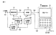
図1に、本発明の第1の実施形態による画像処理装置を含む画像表示装置を示す。画像処理装置は光源輝度算出部11、光源輝度分布算出部13、階調変換部12、光源輝度補正部14及び制御部15を有し、画像表示部20の制御を行う。
[First Embodiment]
FIG. 1 shows an image display apparatus including an image processing apparatus according to the first embodiment of the present invention. The image processing apparatus includes a light source
画像表示部20は、光変調素子である液晶パネル21と、液晶パネル21の背面に設置された複数の光源22を含む光源ユニット(以下、バックライトという)23とにより構成される透過型の液晶表示ユニットである。
The
入力画像101は、光源輝度算出部11及び階調変換部12に入力される。光源輝度算出部11では、バックライト23の光源22と対応付けられた入力画像101の分割領域毎の階調値の情報から各光源22の光源輝度102が算出される。ここで算出される光源輝度102は、言い替えれば、各光源22に対して入力画像101の各光源22に対応する分割領域の情報に基づいて仮決定した輝度を表している。こうして算出された光源輝度102の情報は、光源輝度分布算出部13及び光源輝度補正部14に入力される。
The
光源輝度分布算出部13では、バックライト23の光源22が単独で発光した場合の光源22の輝度分布(以下、個別輝度分布という)に基づき、複数の光源22が同時にある光源輝度で発光した場合のバックライト23の全体の輝度分布(以下、全体輝度分布という)103を算出する。算出された全体輝度分布103の情報は、階調変換部12に入力される。階調変換部12では、全体輝度分布103に基づき入力画像101の各画素について階調の変換を行い、階調変換された変換画像104を出力する。
In the light source luminance
光源輝度補正部14は、光源輝度102の情報から各光源22の光源輝度の所定期間(例えば1フレーム期間)の平均値(以下、平均光源輝度という)を求め、平均光源輝度が大きいほど小さくなるような補正係数を算出する補正係数算出部を含む。光源輝度補正部14は、こうして算出された補正係数に基づいて各光源22の光源輝度102について補正を行い、補正光源輝度105の情報を出力する。
The light source
制御部15では、階調変換部12からの変換画像104の信号と光源輝度補正部14により算出された補正光源輝度105の情報のタイミングを制御し、変換画像104に基づき生成した複合画像信号106を液晶パネル21へ送出すると共に、補正光源輝度105に基づき生成した輝度制御信号107をバックライト23へ送出する。
The
画像表示部20では、複合画像信号106が液晶パネル21へ書き込まれると共に、バックライト23の各光源22が輝度制御信号107に基づいた輝度で発光することによって、画像が表示される。以下、図1の各部についてさらに詳細に説明する。
In the
(光源輝度算出部11)
光源輝度算出部11では、バックライト23の各光源22の輝度(以下、光源輝度という)102を算出する。本実施形態では、バックライト23の各光源22に対応付けて入力画像101が複数の領域に仮想的に分割され、光源輝度算出部11では入力画像101の各分割領域の情報を用いて光源輝度102を算出する。例えば、図2に示すような、光源22が水平方向に5つ、垂直方向に4つ設置された構造のバックライト23においては、入力画像101を各光源22に対応するように破線で示す5×4の領域に分割し、これらの分割領域毎に入力画像101の最大階調を算出する。
(Light source luminance calculation unit 11)
The light source
そして、光源輝度算出部11は分割領域毎に算出された最大階調に基づき、各分割領域に対応する光源22の光源輝度を算出する。例えば、入力画像101が8ビットのデジタル値で表現される場合、入力画像101は0階調から255階調までの256段階の階調を持つので、第i番目の分割領域の最大階調をLmax(i)とすると、光源輝度は次式(1)により算出される。

ここで、γはガンマ値であり、一般に2.2が用いられる。I(i)は、第i番目の光源の光源輝度である。すなわち、光源輝度算出部11は入力画像101の分割領域毎に最大階調Lmax(i)を求め、最大階調Lmax(i)を入力画像101が取り得る最大階調(この場合は“255”)で除して、さらにガンマ値γで補正することにより、光源輝度I(i)を算出する。
Here, γ is a gamma value, and 2.2 is generally used. I (i) is the light source luminance of the i-th light source. That is, the light source
光源輝度I(i)を数式(1)による演算で求める代わりに、ルックアップテーブル(LUT)を用いてもよい。すなわち、予めLmax(i)とI(i)との関係を求めておき、Lmax(i)とI(i)とを対応付けて読み出し専用メモリ(ROM)等によりLUTに記憶保持しておき、Lmax(i)の値によってLUTを参照することで、光源輝度I(i)を求めてもよい。このようにLUTを用いて光源輝度を求める場合にも、何らかの計算処理を伴うので、光源輝度を求める部分を光源輝度算出部11と呼ぶ。
A lookup table (LUT) may be used instead of obtaining the light source luminance I (i) by calculation according to Equation (1). That is, the relationship between L max (i) and I (i) is obtained in advance, and L max (i) and I (i) are associated with each other and stored in the LUT by a read-only memory (ROM) or the like. Alternatively, the light source luminance I (i) may be obtained by referring to the LUT according to the value of L max (i). Even when the light source luminance is obtained by using the LUT as described above, some calculation processing is involved. Therefore, a portion for obtaining the light source luminance is referred to as a light source
なお、本実施形態ではバックライト23の1つの光源22に入力画像101の1つの分割領域を対応させたが、例えば隣接する複数の光源22に入力画像101の1つの分割領域を対応させてもよい。また、入力画像101の各分割領域を図2に示したように光源22の数で均等に分割してもよいが、各分割領域の一部が互いに重なるように分割領域を設定してもよい。
In the present embodiment, one divided region of the
こうして光源輝度算出部11により算出された各光源22の光源輝度102の情報は、光源輝度分布算出部13及び光源輝度補正部14に入力される。
Information on the
(光源輝度分布算出部13)
光源輝度分布算出部13では、以下のように各光源22の光源輝度102に基づいてバックライト23の全体輝度分布103を算出する。
(Light source luminance distribution calculation unit 13)
The light source luminance
図3に、バックライト23の複数の光源22の1つが発光した場合の輝度分布を示す。図3は、説明を簡単にするために1次元で輝度分布を表現しており、横軸が位置、縦軸が輝度を示している。図3は、横軸の下部の丸印で示す位置に光源22が設置されており、中央の白丸で示す1つの光源のみが点灯した場合の輝度分布を示している。図3から分かるように、ある一つの光源が発光した場合の輝度分布は、近傍の光源位置まで広がりを持つ。
FIG. 3 shows a luminance distribution when one of the light sources 22 of the
そこで、光源輝度分布算出部13では、階調変換部12においてバックライト23の全体輝度分布103に基づく階調変換を行うために、図4に示すようにバックライト23の複数の光源22毎の光源輝度102に基づく破線に示す個別輝度分布を合成、すなわち足し合わせることで、実線に示すバックライト23の全体輝度分布103を算出する。
Therefore, in the light source luminance
図4は、バックライト23の複数の光源22が点灯した場合のバックライト23の全体輝度分布103の様子を図3と同様に1次元で模式的に示している。図4の横軸の下部に丸印で示された位置の光源が点灯することにより、各光源は図4に破線で示すような個別輝度分布を持つ。これらの個別輝度分布を足し合わせることにより、図4の実線で示すようなバックライト23の全体輝度分布が算出される。
FIG. 4 schematically shows the
図4の実線に示すような全体輝度分布の算出に際しては、実測値を光源からの距離に関する近似関数として求め、光源輝度分布算出部13に保持しておいてもよいが、本実施形態では図3の破線に示すような光源22の個別輝度分布を光源からの距離と輝度との関係として求め、これらの距離と輝度とを対応付けたLUTをROMに保持する。
When calculating the overall luminance distribution as shown by the solid line in FIG. 4, the actual measurement value may be obtained as an approximate function related to the distance from the light source and held in the light source luminance
図5に、本実施形態における光源輝度分布算出部13の具体例を示す。複数の光源22毎に算出された光源輝度102の情報は、光源輝度分布取得部211に入力される。光源輝度分布取得部211では、LUT212より光源22の輝度分布を取得し、この輝度分布に光源輝度102を掛け合わせることで、図4の破線で示すような光源22毎の個別輝度分布を求める。次に、輝度分布合成部213で各光源22の個別輝度分布を足し合わせることで、図4の実線で示すようなバックライト23の全体輝度分布103が算出され、この全体輝度分布103の情報は階調変換部12へ入力される。
FIG. 5 shows a specific example of the light source luminance
(階調変換部12)
階調変換部12では、光源輝度分布算出部13により算出されたバックライト23の全体輝度分布103に基づき、入力画像101の各画素の階調値を変換して変換画像104を生成する。
(Tone conversion unit 12)
The
光源輝度算出部11により算出される光源輝度102は、入力画像101に基づいて、最大の光源輝度に比べ低い値で算出される。従って、画像表示部20において所望の明るさの画像を表示するためには、液晶パネル21の透過率、すなわち液晶パネル21に書き込む画像信号の階調値を変換する必要がある。入力画像101の画素位置(x,y)の赤、緑及び青のサブ画素の階調値をそれぞれLR(x,y),LG(x,y)及びLB(x,y)とすると、階調変換により得られる変換画像104の赤、緑及び青のサブ画素の階調値LR’(x,y),LG’(x,y)及びLB’(x,y)は、以下のように算出される。
ここで、Id(x,y)は光源輝度分布算出部13で算出されたバックライト23の全体輝度分布103における入力画像101の画素位置(x,y)に対応する輝度(画素対応輝度)を表している。
Here, Id (x, y) is a luminance (pixel-corresponding luminance) corresponding to the pixel position (x, y) of the
階調変換部12において、階調変換後の階調値を数式(2)により演算により求めてもよいが、階調値L及び輝度Idと変換後の階調値L’とを対応付けて保持したLUTを用意し、入力画像101の階調値L(x,y)と輝度Id(x,y)によって当該LUTを参照することで、変換後の階調値L’(x,y)を求めてもよい。
In the
さらに、数式(2)では階調値Lと光源輝度分布Idの値により、変換後の階調値L’が液晶パネル21の最大階調値である“255”を超える場合が発生する。そのような場合、例えば変換後の階調値を“255”で飽和処理してもよいが、飽和処理された階調値に階調つぶれが発生してしまう。そこで、例えばLUTに保持する変換後の階調値を飽和する階調値近傍ではなだらかに変化するよう補正してもよい。 Furthermore, in Equation (2), the converted gradation value L ′ may exceed “255” which is the maximum gradation value of the liquid crystal panel 21 due to the gradation value L and the light source luminance distribution Id. In such a case, for example, the gradation value after conversion may be saturated with “255”, but gradation loss occurs in the gradation value subjected to saturation processing. Therefore, for example, correction may be performed so that the converted gradation value held in the LUT changes gently in the vicinity of the gradation value that saturates.
光源輝度算出部11及び光源輝度分布算出部13では、光源輝度及び光源輝度分布が1フレームの入力画像101の全ての階調値を用いて算出される。従って、階調変換部12に入力画像101としてあるフレームの画像が入力されるタイミングでは、そのフレームの画像に対応する光源輝度分布はまだ算出されていない。そこで、階調変換部12はフレームメモリを備えており、入力画像101を一旦フレームメモリに保持し、1フレーム期間遅延させた後、光源輝度分布算出部13により得られるバックライト23の全体輝度分布103に基づき階調変換を行って変換画像104を生成する。
In the light source
ただし、一般に入力画像101は時間的にある程度連続しており、時間的に連続する画像間の相関は高いため、例えば現フレームの入力画像を1フレーム前の入力画像により求められた全体輝度分布103に基づき階調変換して変換画像104を生成してもよい。この場合、階調変換部12に入力画像101を1フレーム期間遅延させるためのフレームメモリを設ける必要が無くなるので、回路規模を削減することが可能となる。
However, since the
(光源輝度補正部14) 光源輝度補正部14では、光源輝度算出部11で算出された各光源22の光源輝度102に対して、補正係数を乗じることで補正を行い、補正光源輝度105を求める。
(Light Source Luminance Correction Unit 14) The light source
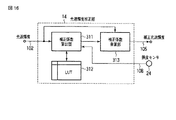
図6に、光源輝度補正部14の具体例を示す。光源輝度補正部14は、光源輝度算出部11で算出された各光源22の光源輝度102を補正するための補正係数を算出する補正係数算出部311、補正係数が保持されているLUT312、及び光源輝度102に補正係数を乗じて補正光源輝度105を求める補正係数乗算部313を有する。以下、図6の各部の動作について詳細に説明する。
FIG. 6 shows a specific example of the light source
補正係数算出部311では、まず各光源22の光源輝度102の平均値(平均光源輝度という)を算出する。例えば、光源22の数がn個の場合、平均光源輝度Iaveは、以下のように算出される。
ここで、I(i)はi番目の光源輝度102を表している。光源22の数nは、画素数に比べれば非常に小さい値であり、従来技術のように画像全体の平均輝度を算出する場合に比べて、処理コストを小さくすることができる。特に、入力画像101が画素数の非常に多いHDTV画像の場合、この効果は顕著である。また、各光源22の光源輝度102の平均値の所定期間(例えば、1フレーム期間)にわたる平均値をIaveに代えて用いてもよい。
Here, I (i) represents the i-th
さらに、数式(3)に示した平均光源輝度Iaveに代えて、以下に示す各光源22の光源輝度102の和(光源輝度和とい)Isumを用いてもよい。
以下の説明では、平均光源輝度Iaveを光源輝度和Isumに置き換えて考えてもよい。また、各光源22の光源輝度102の和の所定期間(例えば、1フレーム期間)にわたる和をIsumに代えて用いてもよい。 In the following description, the average light source luminance Iave may be replaced with the light source luminance sum Isum. Further, the sum of the light source luminances 102 of the respective light sources 22 over a predetermined period (for example, one frame period) may be used instead of Isum.
次に、算出された平均光源輝度Iaveにより、補正係数が保持されているLUT312を参照して、光源輝度102に対する補正係数を求める。LUT312に対応付けられて保持されている平均光源輝度と補正係数の関係は種々考えられるが、基本的には平均光源輝度が小さいほど補正係数が大きくなるように両者の関係は設定される。
Next, based on the calculated average light source luminance Iave, a correction coefficient for the
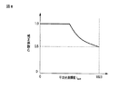
図7に、本実施形態においてLUT312に保持される平均光源輝度Iaveと補正係数Gの関係の一例を示す。平均光源輝度Iaveが所定の閾値未満の小さい領域では、補正係数Gは1.0一定であり、平均光源輝度Iaveが閾値以上の大きい領域では、Iaveの増加につれてGが徐々に小さい値となり、最終的にGが0.5一定となる関係である。本実施形態では、光源22の光源輝度を10ビットで制御することを仮定しているため、平均光源輝度Iaveの最大値は“1023”となり、そのときの補正係数Gは0.5である。
FIG. 7 shows an example of the relationship between the average light source luminance Iave held in the
補正係数GをLUT312に保持する代わりに、平均光源輝度Iaveと補正係数Gの関係を表す関数を補正係数算出部311に保持しておき、平均光源輝度Iaveから補正係数Gを演算する構成としてもよい。
Instead of holding the correction coefficient G in the
こうして補正係数算出部311により算出された補正係数は、補正係数乗算部313へ出力される。補正係数乗算部313では、各光源22の光源輝度102に補正係数を乗じて補正光源輝度105を算出する。すなわち、以下のような演算により補正光源輝度105を算出する。
![]()
![]()
ここで、Ic(i)はi番目の補正光源輝度105を表している。すなわち、補正係数Gが1.0の場合は、光源輝度算出部11で算出された光源輝度I(i)がそのまま補正光源輝度Ic(i)として出力される。補正係数Gが0.5の場合は、光源輝度I(i)の半分の値が補正光源輝度Ic(i)として出力される。
Here, Ic (i) represents the i-th corrected
平均光源輝度Iaveが大きければ、補正係数Gは0.5となるので、バックライト23は光源22が全て点灯した場合の半分の明るさで点灯する。これにより、眩しさが抑制される。例えば、バックライト23の光源22が全て点灯した場合の画面輝度が1,000cd/m2であった場合、補正係数Gが0.5になると、画面輝度は500cd/m2となる。
If the average light source luminance Iave is large, the correction coefficient G is 0.5. Therefore, the
一方、平均光源輝度Iaveが小さい場合は、補正係数Gは1.0となるため、光源22は画面輝度が最大1,000cd/m2となることを仮定して発光することとなる。その結果、光源22は輝度が高く設定されて明るく点灯することとなり、明るい画像領域は明るく、暗い画像領域は暗くといった、CRTのような高ダイナミックレンジの表示が可能となる。 On the other hand, when the average light source luminance Iave is small, the correction coefficient G is 1.0, so that the light source 22 emits light on the assumption that the screen luminance is 1,000 cd / m 2 at the maximum. As a result, the light source 22 is set to have a high luminance and is lit brightly, and a display with a high dynamic range such as a CRT, such as a bright image area being bright and a dark image area being dark, is possible.
次に、消費電力について考える。平均光源輝度Iaveが最大値である“1023”の場合、補正係数G=0.5が光源輝度I(i)に乗じられる。このため平均光源輝度Iaveが“1023”でかつ光源輝度I(i)の補正を行わない場合(補正係数G=1.0に相当)に比較して、消費電力は0.5×10²³/1023=0.5となる。 Next, consider power consumption. When the average light source luminance Iave is “1023” which is the maximum value, the light source luminance I (i) is multiplied by the correction coefficient G = 0.5. Therefore, the power consumption is 0.5 × 10²³/1023 compared to the case where the average light source luminance Iave is “1023” and the light source luminance I (i) is not corrected (corresponding to the correction coefficient G = 1.0). = 0.5.
また、平均光源輝度Iaveが非常に小さく、例えば“100”であった場合には、補正係数Gが1.0であっても、平均光源輝度Iaveが“1023”でかつ光源輝度I(i)の補正を行わない場合(補正係数G=1.0に相当)に比較して、消費電力は1.0×100/1023=0.1となる。従って、画面の最大輝度を1,000cd/m2相当として表示を行っても、最大輝度が500cd/m2相当の場合に比べ、消費電力は大幅に削減されることになる。 When the average light source luminance Iave is very small, for example, “100”, the average light source luminance Iave is “1023” and the light source luminance I (i) even if the correction coefficient G is 1.0. The power consumption is 1.0 × 100/1023 = 0.1 compared to the case where the correction of (1) is not performed (corresponding to the correction coefficient G = 1.0). Therefore, even if the display maximum luminance of the screen as 1,000 cd / m 2 corresponds, the maximum brightness is compared with the 500 cd / m 2 corresponds, power consumption will be significantly reduced.
さらに、平均光源輝度Iaveが“1023”のときの消費電力である0.5をバックライト23の最大消費電力として、常に消費電力が0.5以下となるように補正係数Gを算出することもできる。具体的には、以下の式を満たすように補正係数Gを算出する。
図8に、数式(6)を満たす補正係数Gの最大値と平均光源輝度Iaveの関係を示す。図8のように補正係数Gを設定することにより、画面輝度が最大500cd/m2相当の消費電力以下の消費電力で、画面輝度が最大1,000cd/m2相当の表示を実現することができる。 FIG. 8 shows the relationship between the maximum value of the correction coefficient G that satisfies Equation (6) and the average light source luminance Iave. By setting the correction coefficient G as shown in FIG. 8, the screen brightness is at a maximum 500 cd / m 2 corresponds power less power consumption, that screen luminance to realize a display of up to 1,000 cd / m 2 corresponds it can.
(制御部15)
制御部15では、液晶パネル21への変換画像104の書き込みタイミングと、バックライト23に対して複数の光源22毎の補正光源輝度105を適用するタイミングの制御を行う。
(Control unit 15)
The
制御部15においては、階調変換部12から入力される変換画像104に対し、制御部15内で生成される液晶パネル21を駆動するために必要となる幾つかの同期信号(例えば、水平同期信号及び垂直同期信号等)が付加されることにより、複合画像信号106が生成され、この複合画像信号106が液晶パネル21へ送出される。同時に、制御部15では補正光源輝度105に基づきバックライト23の各光源22を所望の輝度で点灯させるための光源輝度制御信号107が生成され、バックライト23へ送出される。
In the
光源輝度制御信号107の構成は、バックライト23の光源22の種類により異なる。一般に、液晶表示装置におけるバックライトの光源としては、冷陰極管や発光ダイオード(LED)等が用いられている。これらの光源は印加する電圧や電流を制御することにより、その輝度変調が可能である。ただし、一般的には光源に印加する電圧や電流を制御する代わりに、発光期間と非発光期間との比を高速に切り替えることにより輝度を変調するパルス幅変調(pulse width modulation:PWM)制御が用いられる。本実施形態では、例えば比較的発光強度の制御が容易であるLEDをバックライト23の光源22として用い、LEDをPWM制御により輝度変調する。この場合、制御部15では補正光源輝度105に基づいてPWM制御信号が光源輝度制御信号107として生成され、バックライト23へ送出される。
The configuration of the light source
(画像表示部20)
画像表示部20では、制御部15より出力される複合画像信号106を液晶パネル21(光変調素子)に書き込み、同じく制御部15より出力される光源22毎の光源輝度制御信号107に基づいてバックライト23を点灯させることで、入力画像101の表示を行う。なお、上述の通り本実施形態では、バックライト23の光源22としてLEDを用いる。
(Image display unit 20)
In the
以上説明したように、本実施形態によれば高ダイナミックレンジの表示を消費電力の増加を可及的に抑制しつつ小さい回路規模で実現することができる。すなわち、まず表示のダイナミックレンジに関しては、入力画像101に応じた光源22の輝度変調と入力画像101の階調変換を行うことにより、CRT並のダイナミックレンジを実現できる。
As described above, according to the present embodiment, display of a high dynamic range can be realized with a small circuit scale while suppressing an increase in power consumption as much as possible. That is, first, regarding the dynamic range of display, a dynamic range similar to a CRT can be realized by performing luminance modulation of the light source 22 in accordance with the
また、平均光源輝度が大きいほど小さい値となる補正係数を算出し、これを光源輝度に乗じて補正光源輝度を求め、この補正光源輝度に基づいて輝度制御信号107を生成することにより、バックライト23の消費電力の増加を抑えることができる。
Further, a correction coefficient that becomes smaller as the average light source luminance is larger is calculated, multiplied by the light source luminance to obtain a corrected light source luminance, and a
さらに、入力画像から画像全体の平均輝度(APL)を算出し、APLに基づいて光源輝度を制御する従来の手法では、APL算出のための回路規模が大きくなっていたが、本実施形態では画像の平均輝度に代えて平均光源輝度を算出するため、光源数について平均を求めればよい。従って、平均光源輝度の算出のための処理コストは小さく、HDTV画像の場合においても、遙かに小さな回路規模で平均光源輝度の算出を行うことができる。 Further, in the conventional method of calculating the average luminance (APL) of the entire image from the input image and controlling the light source luminance based on the APL, the circuit scale for calculating the APL is large. In order to calculate the average light source luminance instead of the average luminance, the average may be obtained for the number of light sources. Therefore, the processing cost for calculating the average light source luminance is small, and even in the case of HDTV images, the average light source luminance can be calculated with a much smaller circuit scale.
[第2の実施形態]
本発明の第2の実施形態による画像処理装置の基本的な構成は、第1の実施形態と同様であるが、制御部15から出力される光源輝度制御信号107の構成が異なっている。以下、図9〜図14を用いて第2の実施形態による光源輝度制御信号107の構成について詳細に説明する。その他の構成については、第1の実施形態と同様であるため、説明は省略する。
[Second Embodiment]
The basic configuration of the image processing apparatus according to the second embodiment of the present invention is the same as that of the first embodiment, but the configuration of the light source
(制御部15)
第2の実施形態による光源輝度制御信号107は、入力画像101の1フレーム期間内に発光期間と非発光期間が設定され、光源22の列毎に、すなわち画面垂直方向において発光期間と非発光期間の開始タイミングが異なっている。
(Control unit 15)
In the light source
図9に、液晶パネル21への画像信号の書き込みタイミングと光源22の発光期間との関係を示す。図9は、縦軸が画面垂直位置、横軸が時間を示している。液晶パネル21への画像信号の書き込み開始タイミングは、液晶パネル21の1ライン目より線順次でタイミングが少しずつ遅れて最終ラインへ向かって書き込まれる。正確には、現フレームの最終ラインを書き込み後、所定のブランキング期間を経た後に、次のフレームの1ライン目の書き込みが開始されるが、ここでは説明を簡単にするために、ブランキング期間を0として図示している。 FIG. 9 shows the relationship between the image signal writing timing to the liquid crystal panel 21 and the light emission period of the light source 22. In FIG. 9, the vertical axis represents the screen vertical position, and the horizontal axis represents time. The writing start timing of the image signal to the liquid crystal panel 21 is written toward the final line with a little delay in the line sequential order from the first line of the liquid crystal panel 21. To be precise, after writing the last line of the current frame and after a predetermined blanking period, writing of the first line of the next frame is started. Is shown as 0.
光源22は、液晶パネル21の複数のライン毎に発光/非発光が制御されるため、図9に示すようにバックライト23の画面垂直方向の光源数に対応した単位で発光することとなる。図9は、図2に示したように画面垂直方向の光源数が4の場合を示している。光源22は、光源輝度制御信号107により補正光源輝度105に応じて1フレーム期間の非発光期間と発光期間の比率が制御される。
Since light emission / non-light emission is controlled for each of a plurality of lines of the liquid crystal panel 21, the light source 22 emits light in units corresponding to the number of light sources in the screen vertical direction of the
図9は、1フレーム期間(液晶パネル21に対する現フレームの画像信号の書き込み開始タイミングと次フレームの画像信号の書き込み開始タイミングとの間の期間)の前半及び後半に、それぞれ非発光期間及び発光期間が設定され、すなわち補正光源輝度105が10ビット表現で“512”の場合を示している。
FIG. 9 shows a non-light emission period and a light emission period in the first half and the second half of one frame period (a period between the writing start timing of the image signal of the current frame and the writing start timing of the image signal of the next frame). Is set, that is, the correction
光源22の1フレーム期間内での発光期間の位置は様々に設定され得るが、図9に示すように液晶パネル21に現フレームの画像信号を書き込んだ後、できるだけ長い非発光期間を経過した後に光源22が発光することが好ましい。すなわち、次フレームの画像信号の書き込み開始タイミングを光源22の発光期間から非発光期間への変化タイミングとして固定し、補正光源輝度105に応じて発光期間の開始タイミングを決定すればよい。この理由は次の通りである。
Although the position of the light emission period within one frame period of the light source 22 can be set variously, after writing the image signal of the current frame on the liquid crystal panel 21 as shown in FIG. It is preferable that the light source 22 emits light. That is, the start timing of writing the image signal of the next frame is fixed as the change timing from the light emission period of the light source 22 to the non-light emission period, and the start timing of the light emission period may be determined according to the corrected
液晶パネル21は、液晶材料の応答特性のため、画像信号が書き込まれた後、一定期間の後に所望の透過率に到達する。従って、光源22はできる限り所望の液晶パネル21の透過率に到達した後に発光した方が正しい明るさで表示されるため、発光期間は1フレーム期間の後半に設定されるのが望ましい。また、光源22の発光期間の開始タイミングを画面垂直方向にずらすことにより、液晶パネル21への画像信号の書き込みタイミングと発光期間の開始タイミングとの間の期間(非発光期間)を長く設定することが可能となり、より正しい明るさで画像を表示することが可能となる。 Due to the response characteristics of the liquid crystal material, the liquid crystal panel 21 reaches a desired transmittance after a certain period after the image signal is written. Accordingly, since the light source 22 is displayed with the correct brightness when it emits light after reaching the desired transmittance of the liquid crystal panel 21 as much as possible, it is desirable to set the light emission period in the second half of one frame period. Further, by shifting the start timing of the light emission period of the light source 22 in the vertical direction of the screen, a period (non-light emission period) between the writing timing of the image signal to the liquid crystal panel 21 and the start timing of the light emission period is set longer. This makes it possible to display an image with more correct brightness.
図10は、液晶パネル21への画像信号の書き込みタイミングと光源22の発光期間の関係を示し、特に補正光源輝度105が“256”の場合の発光期間のタイミングを示している。図9及び図10を比較して明らかなように、本実施形態では光源22の発光期間から非発光期間への変化タイミングについては、補正光源輝度105によらず同じタイミングとし、発光期間の開始タイミングを補正光源輝度105に応じて変化させることで光源輝度を変化させている。
FIG. 10 shows the relationship between the writing timing of the image signal to the liquid crystal panel 21 and the light emission period of the light source 22, and particularly shows the timing of the light emission period when the corrected
このように1フレーム期間内に一定の非発光期間を設定することにより、液晶表示装置に代表されるホールド型表示装置で動画を表示した際に発生するホールドぼけを低減することが可能となり、よりはっきりとした動画を表示することが可能となる。特に、本実施形態では光源輝度の平均値(平均光源輝度Iave)が大きい場合、例えば図7に示したように補正係数Gが0.5に設定され、発光期間は最大でも1フレーム期間の半分となる。従って、動画のぼけが視認されやすい明るい画像において、ホールドぼけを効果的に低減することができる。 Thus, by setting a certain non-light emitting period within one frame period, it becomes possible to reduce hold blur that occurs when a moving image is displayed on a hold type display device typified by a liquid crystal display device. A clear video can be displayed. In particular, in this embodiment, when the average value of the light source luminance (average light source luminance Iave) is large, for example, as shown in FIG. 7, the correction coefficient G is set to 0.5, and the light emission period is at most half of one frame period. It becomes. Accordingly, it is possible to effectively reduce hold blur in a bright image in which moving image blur is easily visible.
光源輝度制御信号107の変形例として、図11に示すように第1発光制御期間と第2発光制御期間を設定し、各々の発光制御期間で異なる光源輝度制御信号107に従って光源輝度を変調するようにすることもできる。図11によると、例えば第1発光制御期間では第1発光制御期間をさらに複数の期間(サブ制御期間という)に分割し、各サブ制御期間内で発光期間と非発光期間の比率を変更することで光源輝度を変調する。一方、第2発光制御期間では時にサブ制御期間への分割を行わず、図9及び図10と同様に発光期間と非発光期間との比率を変化させることで光源輝度を変調する。
As a modification of the light source
ここで、補正光源輝度105が所定の閾値より小さい場合は、第1発光制御期間のみを用いて光源輝度を変調し、補正光源輝度105が所定の閾値以上であれば、第1発光制御期間と第2発光制御期間を用いて光源輝度を変調する。
Here, when the corrected
例えば、閾値が“512”であり、補正光源輝度105が“256”の場合は、図12に示すように第1発光制御期間で光源輝度を変調し、第2発光制御期間は非発光とする。図12では、第1発光制御期間がさらに4つのサブ制御期間に分割されており、各サブ制御期間の50%の期間を発光期間、残りの50%の期間を非発光期間として、“256”の補正光源輝度105に従って光源22を発光させている。
For example, when the threshold value is “512” and the correction
また、補正光源輝度105が“768”の場合は、図13に示すように第1発光制御期間は発光期間が100%、非発光期間が0%、つまり光源22が常に発光している状態とし、第2発光制御期間は発光期間が50%、残りの50%が非発光期間となって“768”の補正光源輝度105の発光を設定する。
When the corrected
図9及び図10のように発光期間を制御して光源輝度の変調を行った場合、補正光源輝度105により発光期間と非発光期間が大きく変化することとなり、補正光源輝度105に応じて動画ぼけの発生量も大きく変化することになる。これに対し、図12及び図13に示すように光源輝度の変調を行った場合、補正光源輝度105が所定の閾値以下では、動画ぼけの発生量に影響の大きい第2発光制御期間は常に非発光となり、動画ぼけの発生量が変化しないため、動画の画質をより安定させることができる。
When the light emission period is controlled by controlling the light emission period as shown in FIGS. 9 and 10, the light emission period and the non-light emission period are greatly changed by the corrected
なお、図9及び図10では、説明を簡単にするためにバックライト23全体の明るさが同じように変調される例を示した。しかし、補正光源輝度105は入力画像101に応じて光源22毎に異なる値に設定されるため、実際には図14に示すように光源位置及び時間毎に異なる発光期間で発光することになる。
9 and 10 show examples in which the brightness of the
以上説明したように、第2の実施形態によれば第1の実施形態と同様にCRTのような高ダイナミックレンジの表示を消費電力の増加を可及的に抑制しながら小さい回路規模で実現できることに加えて、動画ぼけを効果的に低減するという効果が得られる。 As described above, according to the second embodiment, display of a high dynamic range such as a CRT can be realized with a small circuit scale while suppressing an increase in power consumption as much as possible in the same manner as the first embodiment. In addition, the effect of effectively reducing moving image blur can be obtained.
[第3の実施形態]
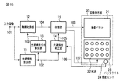
図15に、本発明の第2の実施形態による画像処理装置を含む画像表示装置を示す。第3の実施形態の画像処理装置の基本的な構成は、図1に示した第1の実施形態と同様である。第3の実施形態では、画像表示部20に照度センサ24を備え、光源輝度補正部14において光源輝度算出部11により算出される光源輝度102と照度センサ24からの照度信号108に基づいて補正光源輝度105を算出する。以下、第3の実施形態における光源輝度補正部14について詳細に説明する。その他の構成については、第1の実施形態と同様であるため、説明は省略する
(光源輝度補正部14)
第3の実施形態において、光源輝度補正部14には光源輝度算出部11からの光源輝度102に加えて、画像表示部20に設置された照度センサ24からの照度信号108が入力される。照度信号108は視聴環境、すなわち画像表示装置が設置された室内などの環境の照度を表している。光源輝度補正部14では、光源輝度102と照度信号108に基づいて補正光源輝度105を算出する。
[Third Embodiment]
FIG. 15 shows an image display apparatus including an image processing apparatus according to the second embodiment of the present invention. The basic configuration of the image processing apparatus of the third embodiment is the same as that of the first embodiment shown in FIG. In the third embodiment, the
In the third embodiment, in addition to the
図16に、第3の実施形態における光源輝度補正部14の具体例を示す。補正係数算出部311では、第1の実施形態と同様に所定期間、例えば1フレーム期間の各光源22の光源輝度の平均値(平均光源輝度Iave)を算出する。さらに、補正係数算出部311は平均光源輝度Iave及び照度センサ24からの照度信号108の値SによりLUT312を参照して補正係数Gを算出する。
FIG. 16 shows a specific example of the light source
図17を用いて、LUT312の具体的な一例を説明する。図6中に示した第1の実施形態におけるLUT312に対し、照度S毎に異なる補正係数Gと平均光源輝度Iaveとが対応付けられて保持されている点が異なる。照度Sが1.0、すなわち視聴環境が十分に明るい場合を基準として、補正係数Gは照度Sが小さくなるにつれて小さい値となるように設定される。
A specific example of the
さらに、平均光源輝度Iaveが大きい場合には、照度Sが低下した際に画像表示部20で表示される画像が非常に眩しく感じられる。このため、平均光源輝度Iaveが大きい領域では、補正係数Gは照度Sが小さくなるにつれてより顕著に小さくなるように設定される。
Further, when the average light source luminance Iave is large, the image displayed on the
一方、平均光源輝度Iaveが小さい場合には、画像表示部20で表示される画像は元々それほど明るくないために、視聴環境の照度が低下しても眩しさの感じ方は小さくなる。そこで、平均光源輝度Iaveが大きい場合に比べて、平均光源輝度Iaveが小さい場合には、照度Sに対する補正係数Gの変化は小さく設定される。
On the other hand, when the average light source luminance Iave is small, the image displayed on the
なお、照度S毎の補正係数Gと平均光源輝度Iaveの関係は、図17に示すような3種類に限られたものではなく、より多くの照度S毎の補正係数Gと平均光源輝度Iaveの関係をLUT312に保持しておくことで、詳細な制御が可能となる。
The relationship between the correction coefficient G for each illuminance S and the average light source luminance Iave is not limited to the three types as shown in FIG. By holding the relationship in the
また、図17のようにLUT312において離散的に設定された照度S毎に補正係数Gと平均光源輝度Iaveとを対応付けて保持しておき、保持されていない照度Sに対しては保持されている補正係数Gを用いて補間を行い、任意の照度Sに対する補正係数Gを求めるようにすることもできる。
Further, as shown in FIG. 17, the correction coefficient G and the average light source luminance Iave are held in association with each illuminance S set discretely in the
補正係数乗算部313では、上記のようにして求められた補正係数Gを第1の実施形態と同様に各光源22の光源輝度102に乗じて、補正光源輝度105を算出する。
The correction
次に、照度センサ24からの照度信号108を用いた補正係数Gの設定方法の変形例を示す。これまで述べた例では、補正係数は1フレームの各光源22の光源輝度に対して1つの値が用いられるが、変形例では光源輝度算出部11で算出された光源輝度102毎、すなわち光源22毎に補正係数を変化させる。
Next, a modification of the method for setting the correction coefficient G using the
図18は、第3の実施形態における光源輝度補正部14の変形例であり、第1及び第2LUT321及び322が設けられている。第1LUT321には、図17に示す照度S毎の第1補正係数Gと平均光源輝度Iaveとが対応付けられて保持されている。第2LUT322には、例えば図19に示す照度S毎の第2補正係数αと光源輝度とが対応付けられて保持されている。
FIG. 18 is a modified example of the light source
補正係数算出部311では、まず平均光源輝度Iaveと照度Sにより第1LUT321を参照して、第1補正係数Gを求める。次に、光源22毎の光源輝度I(i)と照度Sにより第2LUT322を参照して、第2補正係数αを求める。そして、以下のように第1補正係数Gと第2補正係数αを乗算することで、光源22毎の補正係数g(i)を算出する。
以下に、第2補正係数αの役割を説明する。例えば、複数の光源22の多くは光源輝度が高く算出され、一部のみ光源輝度が低く算出された場合、平均光源輝度Iaveは大きい値となる。ここで、照度Sが大きい場合、すなわち視聴環境が明るい場合は、画面の眩しさを抑制するため、第1LUT321からの第1補正係数Gはやや小さい値となる。そのため、第1補正係数Gのみを光源輝度102に乗じた場合、光源22の多く多くは眩しさを抑えるために適切な光源輝度に補正される。一方、光源輝度の低い一部の光源では、視聴環境が明るいにも関わらず、第1補正係数Gにより過度に暗く設定されるため、光源輝度が低い領域の表示画像が見にくくなってしまう。
Hereinafter, the role of the second correction coefficient α will be described. For example, when many of the plurality of light sources 22 are calculated to have a high light source luminance and only a part of the light source luminance is calculated to be low, the average light source luminance Iave is a large value. Here, when the illuminance S is large, that is, when the viewing environment is bright, the first correction coefficient G from the
そこで、第2LUT322において、照度Sが高い場合は光源輝度Iが小さいときの第2補正係数αが大きい値となるような光源輝度と第2補正係数αの関係を保持しておく。このようにするとにより、光源輝度が低い一部の光源では第2補正係数αが大きい値となるため、過度に暗く光源輝度が補正されることを抑制することができる。
Therefore, in the
一方、複数の光源22の多くは光源輝度が低く算出され、一部のみ光源輝度が高く算出された場合、平均光源輝度Iaveは小さい値となる。このとき、照度Sが小さい値、すなわち、視聴環境が暗い場合は、表示画像を高ダイナミックレンジに表示するために、第1LUT321からの第1補正係数Gは大きい値となる。そのため、第1補正係数Gのみを光源輝度に乗じた場合、光源輝度の高い一部の光源は、視聴環境が暗いにも関わらず第1補正係数Gにより過度に明るく設定され、表示画像が眩しく感じられてしまう。
On the other hand, in many of the plurality of light sources 22, when the light source luminance is calculated to be low and only a part of the light source luminance is calculated to be high, the average light source luminance Iave is a small value. At this time, when the illuminance S is a small value, that is, when the viewing environment is dark, the first correction coefficient G from the
そこで、第2LUT322において、照度Sが低い場合は光源輝度Iが大きいときの第2補正係数αが小さい値となるような光源輝度と第2補正係数αの関係を保持しておく。このようにすると、光源輝度が高い一部の光源では第2補正係数αが小さい値となるため、過度に明るく光源輝度が補正されることを抑制することができる。
Therefore, in the
上記のように光源22毎に第1補正係数Gまたは第2補正係数αに基づいて数式(7)により算出された補正係数g(i)を以下のように各光源22の光源輝度102に乗じることで、補正光源輝度105を算出する。
ここで、Ic(i)はi番目の補正光源輝度105、I(i)はi番目の光源輝度102を表している。
Here, Ic (i) represents the i-th corrected
このように光源22毎に補正係数を算出することで、1フレーム内で光源輝度が高い光源と低い光源が混在する場合にも、光源輝度を視聴環境の照度に応じた適切な値に補正することが可能となる。 By calculating the correction coefficient for each light source 22 in this way, even when a light source with a high light source luminance and a light source with a low light source coexist in one frame, the light source luminance is corrected to an appropriate value according to the illuminance of the viewing environment. It becomes possible.
以上説明したように、本実施形態によれば第1、第2の実施形態と同様に、CRTのような高ダイナミックレンジの表示を消費電力の増加を可及的に抑制しながら小さい回路規模で実現すると共に、視聴環境の明るさに応じた適切な表示輝度を実現することができるという効果が得られる。 As described above, according to the present embodiment, as in the first and second embodiments, a high dynamic range display such as a CRT can be achieved with a small circuit scale while suppressing an increase in power consumption as much as possible. In addition to this, there is an effect that it is possible to realize an appropriate display luminance according to the brightness of the viewing environment.
以上述べた第1乃至第3の実施形態では、液晶パネル21とバックライト23を組み合わせた透過型液晶表示装置について説明してきたが、本発明はこれ以外の様々な画像表示装置にも適用が可能である。例えば、光変調素子としての液晶パネルとハロゲン光源のような光源ユニットを組み合わせた投射型液晶表示装置にも、本発明を適用可能である。また、光源ユニットとしてのハロゲン光源からの光の反射を制御することにより画像の表示を行うデジタルマイクロミラーデバイスを光変調素子として利用する投射型の画像表示装置にも、本発明を適用することができる。
In the first to third embodiments described above, the transmissive liquid crystal display device in which the liquid crystal panel 21 and the
本発明は上記実施形態そのままに限定されるものではなく、実施段階ではその要旨を逸脱しない範囲で構成要素を変形して具体化できる。また、上記実施形態に開示されている複数の構成要素の適宜な組み合わせにより、種々の発明を形成できる。例えば、実施形態に示される全構成要素から幾つかの構成要素を削除してもよい。さらに、異なる実施形態にわたる構成要素を適宜組み合わせてもよい。 The present invention is not limited to the above-described embodiments as they are, and can be embodied by modifying the constituent elements without departing from the scope of the invention in the implementation stage. In addition, various inventions can be formed by appropriately combining a plurality of components disclosed in the embodiment. For example, some components may be deleted from all the components shown in the embodiment. Furthermore, constituent elements over different embodiments may be appropriately combined.
11・・・光源輝度算出部
12・・・階調変換部
13・・・光源輝度分布算出部
14・・・光源輝度補正部
15・・・制御部
20・・・画像表示部
21・・・液晶パネル(光変調素子)
22・・・光源
23・・・バックライト(光源ユニット)
24・・・照度センサ
101・・・入力画像
102・・・光源輝度
103・・・全体輝度分布
104・・・変換画像
105・・・補正光源輝度
106・・・複合画像信号
107・・・光源輝度制御信号
108・・・照度信号
211・・・輝度分布取得部
212・・・ルックアップテーブル
213・・・輝度分布合成部
311・・・補正係数算出部
312・・・ルックアップテーブル
313・・・補正係数乗算部
321,322・・・ルックアップテーブル
DESCRIPTION OF
22 ...
24 ...
Claims (12)
入力画像の前記複数の光源毎に対応付けられた分割領域の階調値の情報を用いて前記複数の光源毎の光源輝度を算出する光源輝度算出部と、
前記光源毎の前記光源輝度の分布を表す個別輝度分布を複数合成して前記光源ユニットの全体輝度分布を算出する光源輝度分布算出部と、
前記全体輝度分布に基づいて前記入力画像の階調を前記入力画像の画素毎に変換して変換画像を得る階調変換部と、
前記複数の光源輝度の平均値または和を代表値として算出し、該算出した代表値が大きいほど小さい値となる補正係数を算出する補正係数算出部を含み、前記光源輝度に前記補正係数を乗じることにより前記光源輝度を補正して補正光源輝度を求める光源輝度補正部と、
前記変換画像に基づいて前記画像信号を生成し、前記補正光源輝度に基づいて前記輝度制御信号を生成する制御部と、
を備える画像処理装置。 An image processing apparatus for an image display apparatus, comprising: a light source unit capable of modulating a luminance according to a luminance control signal for each of a plurality of light sources; and a light modulation element that modulates light from the light source unit according to an image signal,
A light source luminance calculating unit that calculates light source luminance for each of the plurality of light sources using information on gradation values of divided regions associated with the plurality of light sources of the input image;
A light source luminance distribution calculation unit that calculates a total luminance distribution of the light source unit by combining a plurality of individual luminance distributions representing the distribution of the light source luminance for each light source;
A gradation converter that converts the gradation of the input image for each pixel of the input image based on the overall luminance distribution to obtain a converted image;
A correction coefficient calculation unit that calculates an average value or sum of the plurality of light source luminances as a representative value, and calculates a correction coefficient that decreases as the calculated representative value increases, and multiplies the light source luminance by the correction coefficient; A light source luminance correction unit for correcting the light source luminance to obtain a corrected light source luminance;
A control unit that generates the image signal based on the converted image and generates the luminance control signal based on the corrected light source luminance;
An image processing apparatus comprising:
前記制御部は、前記光変調素子への現フレームの画像信号の書き込み開始タイミングと前記光変調素子への次フレームの画像信号の書き込み開始タイミングとの間の期間に前記光源ユニットの複数の光源毎に非発光期間及び発光期間が順次配置され、前記非発光期間と前記発光期間との比率を変更することにより前記光源ユニットの複数の光源毎の明るさを制御するように、前記輝度制御信号が構成されることを特徴とする請求項1記載の画像処理装置。 The light modulation element is configured to modulate light from the light source unit by writing the image signal in units of frames,
The control unit is provided for each of a plurality of light sources of the light source unit during a period between the writing start timing of the image signal of the current frame to the light modulation element and the writing start timing of the image signal of the next frame to the light modulation element. The luminance control signal is arranged such that a non-light emission period and a light emission period are sequentially arranged, and brightness of each of the plurality of light sources of the light source unit is controlled by changing a ratio of the non-light emission period and the light emission period. The image processing apparatus according to claim 1, wherein the image processing apparatus is configured.
前記補正光源輝度が所定の閾値より小さい場合は、前記第1発光制御期間を分割した複数のサブ制御期間に配置した前記光源ユニットの複数の光源毎の発光期間と非発光期間との比率を変更することで前記光源ユニットの複数の光源毎の明るさを制御し、
前記補正光源輝度が当該閾値以上の場合は、前記第1発光制御期間を全て前記光源ユニットの光源の発光期間とし、前記第2発光制御期間に順次配置した、前記光源ユニットの複数の光源毎の非発光期間と発光期間との比率を変更することにより前記光源ユニットの複数の光源毎の明るさを制御するように、前記輝度制御信号が構成されることを特徴とする請求項2記載の画像処理装置。 The control unit includes a first light emission control period and a second emission period in a period between a writing start timing of the image signal of the current frame to the light modulation element and a writing start timing of the image signal of the next frame to the light modulation element. Arrange the light emission control period sequentially,
When the corrected light source luminance is smaller than a predetermined threshold, the ratio between the light emission period and the non-light emission period for each of the plurality of light sources of the light source unit arranged in the plurality of sub-control periods divided from the first light emission control period is changed. To control the brightness of each light source of the light source unit,
When the corrected light source luminance is equal to or higher than the threshold, all the first light emission control periods are set as the light emission periods of the light sources of the light source units, and are sequentially arranged in the second light emission control period for each of the plurality of light sources of the light source unit. 3. The image according to claim 2, wherein the luminance control signal is configured to control the brightness of each of the plurality of light sources of the light source unit by changing a ratio between a non-light emitting period and a light emitting period. Processing equipment.
前記補正係数算出部は、前記複数の光源輝度から前記代表値を算出し、該算出した代表値により前記ルックアップテーブルを参照して前記補正係数を算出することを特徴とする請求項1記載の画像処理装置。 The light source luminance correction unit has a lookup table that stores and holds the representative value and the correction coefficient in association with each other,
The correction coefficient calculation unit calculates the representative value from the plurality of light source luminances, and calculates the correction coefficient by referring to the lookup table based on the calculated representative value . Image processing device.
前記補正係数算出部は、前記代表値が大きいほど小さく、かつ前記照度が小さいほど小さい値を持つように前記補正係数を算出することを特徴とする請求項1記載の画像処理装置。 An illuminance sensor for detecting the illuminance of the viewing environment of the image display device;
The image processing apparatus according to claim 1, wherein the correction coefficient calculation unit calculates the correction coefficient so that the smaller the representative value is, and the smaller the illuminance is, the smaller the value is.
前記補正係数算出部は、前記代表値が大きいほど小さく、かつ前記照度が小さいほど小さい値を持つ第1光源輝度補正係数と、前記複数の光源毎に前記光源輝度が大きいほど小さく、かつ前記照度が小さいほど小さい値を持つ第2光源輝度補正係数を算出し、前記第1光源輝度補正係数と前記第2光源輝度補正係数とを乗算して前記代表値が大きいほど小さい値となる補正係数を算出することを特徴とする請求項1記載の画像処理装置。 An illuminance sensor for detecting the illuminance of the viewing environment of the image display device;
The correction coefficient calculation unit has a first light source luminance correction coefficient having a smaller value as the representative value is larger and a smaller value as the illuminance is smaller, and smaller as the light source luminance is larger for each of the plurality of light sources, and the illuminance. A second light source luminance correction coefficient having a smaller value is calculated as the value is smaller, and a correction coefficient that is smaller as the representative value is larger by multiplying the first light source luminance correction coefficient and the second light source luminance correction coefficient. The image processing apparatus according to claim 1, wherein the image processing apparatus is calculated.
入力画像の前記複数の光源毎に対応付けられた分割領域の階調値の情報を用いて前記複数の光源毎の光源輝度を算出する光源輝度算出部と、
前記光源毎の前記光源輝度の分布を表す個別輝度分布を複数合成して前記光源ユニットの全体輝度分布を算出する光源輝度分布算出部と、
前記全体輝度分布に基づいて前記入力画像の階調を前記入力画像の画素毎に変換して変換画像を得る階調変換部と、
前記複数の光源輝度の平均値または和を代表値として算出し、該算出した代表値が大きいほど小さい値となる補正係数を算出する補正係数算出部を含み、前記光源輝度に前記補正係数を乗じることにより前記光源輝度を補正して補正光源輝度を求める光源輝度補正部と、
前記変換画像に基づいて前記画像信号を生成し、前記補正光源輝度に基づいて前記輝度制御信号を生成する制御部と、
を備える画像表示装置。 An image display unit including a light source unit capable of luminance modulation according to a luminance control signal for each of a plurality of light sources, and a light modulation element for modulating light from the light source unit according to an image signal;
A light source luminance calculating unit that calculates light source luminance for each of the plurality of light sources using information on gradation values of divided regions associated with the plurality of light sources of the input image;
A light source luminance distribution calculation unit that calculates a total luminance distribution of the light source unit by combining a plurality of individual luminance distributions representing the distribution of the light source luminance for each light source;
A gradation converter that converts the gradation of the input image for each pixel of the input image based on the overall luminance distribution to obtain a converted image;
A correction coefficient calculation unit that calculates an average value or sum of the plurality of light source luminances as a representative value, and calculates a correction coefficient that decreases as the calculated representative value increases, and multiplies the light source luminance by the correction coefficient; A light source luminance correction unit for correcting the light source luminance to obtain a corrected light source luminance;
A control unit that generates the image signal based on the converted image and generates the luminance control signal based on the corrected light source luminance;
An image display device comprising:
Priority Applications (5)
| Application Number | Priority Date | Filing Date | Title |
|---|---|---|---|
| JP2008331348A JP4818351B2 (en) | 2008-12-25 | 2008-12-25 | Image processing apparatus and image display apparatus |
| CN2009801022772A CN101933078B (en) | 2008-12-25 | 2009-12-09 | Image processing apparatus and image display apparatus |
| KR1020107015600A KR101148394B1 (en) | 2008-12-25 | 2009-12-09 | Image processing device and image display device |
| PCT/JP2009/070619 WO2010073909A1 (en) | 2008-12-25 | 2009-12-09 | Image processing apparatus and image display apparatus |
| US12/877,227 US8144173B2 (en) | 2008-12-25 | 2010-09-08 | Image processing apparatus and image display apparatus |
Applications Claiming Priority (1)
| Application Number | Priority Date | Filing Date | Title |
|---|---|---|---|
| JP2008331348A JP4818351B2 (en) | 2008-12-25 | 2008-12-25 | Image processing apparatus and image display apparatus |
Publications (3)
| Publication Number | Publication Date |
|---|---|
| JP2010152174A JP2010152174A (en) | 2010-07-08 |
| JP2010152174A5 JP2010152174A5 (en) | 2010-10-28 |
| JP4818351B2 true JP4818351B2 (en) | 2011-11-16 |
Family
ID=42287525
Family Applications (1)
| Application Number | Title | Priority Date | Filing Date |
|---|---|---|---|
| JP2008331348A Expired - Fee Related JP4818351B2 (en) | 2008-12-25 | 2008-12-25 | Image processing apparatus and image display apparatus |
Country Status (5)
| Country | Link |
|---|---|
| US (1) | US8144173B2 (en) |
| JP (1) | JP4818351B2 (en) |
| KR (1) | KR101148394B1 (en) |
| CN (1) | CN101933078B (en) |
| WO (1) | WO2010073909A1 (en) |
Families Citing this family (70)
| Publication number | Priority date | Publication date | Assignee | Title |
|---|---|---|---|---|
| WO2011001673A1 (en) * | 2009-07-01 | 2011-01-06 | パナソニック株式会社 | Image display device, control device for same, and integrated circuit |
| JP5113940B2 (en) | 2009-09-22 | 2013-01-09 | 株式会社東芝 | Image processing apparatus and image display apparatus |
| JP4951096B2 (en) | 2010-07-07 | 2012-06-13 | シャープ株式会社 | Liquid crystal display |
| CN102376255B (en) * | 2010-08-06 | 2014-02-19 | 晨星软件研发(深圳)有限公司 | Backlight brightness control circuit and method |
| JP5284321B2 (en) | 2010-08-24 | 2013-09-11 | 株式会社東芝 | Image display device |
| WO2012030622A1 (en) * | 2010-08-31 | 2012-03-08 | Dolby Laboratories Licensing Corporation | Ambient black level |
| JP5091995B2 (en) | 2010-09-03 | 2012-12-05 | 株式会社東芝 | Liquid crystal display |
| US20130249967A1 (en) * | 2010-12-13 | 2013-09-26 | Zoran (France) S.A. | Backlight compensation pattern |
| US8963800B2 (en) * | 2011-02-10 | 2015-02-24 | Sharp Kabushiki Kaisha | Multi-display device and image display device |
| US9001029B2 (en) * | 2011-02-15 | 2015-04-07 | Basf Se | Detector for optically detecting at least one object |
| JP5039218B1 (en) * | 2011-03-15 | 2012-10-03 | シャープ株式会社 | Video display device |
| JP4987134B1 (en) * | 2011-03-15 | 2012-07-25 | シャープ株式会社 | Video display device |
| CN103430230B (en) * | 2011-03-15 | 2016-08-17 | 夏普株式会社 | Video display devices |
| JP4991949B1 (en) * | 2011-04-07 | 2012-08-08 | シャープ株式会社 | Video display device and television receiver |
| JP5270730B2 (en) | 2011-08-03 | 2013-08-21 | シャープ株式会社 | Video display device |
| CN103918022B (en) | 2011-11-11 | 2016-10-12 | 杜比实验室特许公司 | Backlight and display system for display |
| JP5221780B1 (en) | 2012-02-03 | 2013-06-26 | シャープ株式会社 | Video display device and television receiver |
| JP5197858B1 (en) * | 2012-02-15 | 2013-05-15 | シャープ株式会社 | Video display device and television receiver |
| JP5805116B2 (en) | 2012-03-22 | 2015-11-04 | キヤノン株式会社 | Light source control device, control method therefor, and liquid crystal display device |
| JP2013238693A (en) * | 2012-05-14 | 2013-11-28 | Sharp Corp | Image display apparatus, image display method, and program |
| JP5498532B2 (en) * | 2012-05-23 | 2014-05-21 | シャープ株式会社 | Video display device |
| CN107978283B (en) | 2012-06-15 | 2021-12-10 | 杜比实验室特许公司 | System and method for controlling dual modulation display |
| DE112013003565B4 (en) | 2012-07-19 | 2021-04-01 | Fujifilm Corporation | Image display apparatus and method |
| US9542893B2 (en) * | 2012-09-07 | 2017-01-10 | Sahrp Kabushiki Kaisha | Image display device, recording medium, and method to control light sources based upon generated approximate curves |
| US20150242701A1 (en) * | 2012-09-20 | 2015-08-27 | Sharp Kabushiki Kaisha | Image processing device, image display device, image capture device, image printing device, gradation conversion method, and computer readable medium |
| JP6249688B2 (en) * | 2012-10-16 | 2017-12-20 | キヤノン株式会社 | Display device, display method, and program |
| KR102088685B1 (en) | 2012-12-19 | 2020-03-13 | 바스프 에스이 | Detector for optically detecting at least one object |
| KR102076042B1 (en) * | 2013-01-17 | 2020-02-12 | 삼성디스플레이 주식회사 | Method of displaying an image, display apparatus performing the same, method and apparatus of calculating a correction value applied to the same |
| CN109521397B (en) | 2013-06-13 | 2023-03-28 | 巴斯夫欧洲公司 | Detector for optically detecting at least one object |
| KR20160019067A (en) | 2013-06-13 | 2016-02-18 | 바스프 에스이 | Detector for optically detecting an orientation of at least one object |
| CN105210190A (en) | 2013-06-13 | 2015-12-30 | 巴斯夫欧洲公司 | Optical detector and method for manufacturing the same |
| JP6242092B2 (en) * | 2013-06-14 | 2017-12-06 | キヤノン株式会社 | Display device, display device control method, and program |
| CN105637320B (en) | 2013-08-19 | 2018-12-14 | 巴斯夫欧洲公司 | Fluorescence detector |
| WO2015024870A1 (en) | 2013-08-19 | 2015-02-26 | Basf Se | Detector for determining a position of at least one object |
| JP6042785B2 (en) * | 2013-10-22 | 2016-12-14 | 株式会社ジャパンディスプレイ | Display device, electronic apparatus, and driving method of display device |
| JP2015194747A (en) * | 2014-03-27 | 2015-11-05 | 株式会社ジャパンディスプレイ | Display device and display device driving method |
| US11041718B2 (en) | 2014-07-08 | 2021-06-22 | Basf Se | Detector for determining a position of at least one object |
| CN104240662B (en) * | 2014-09-10 | 2016-06-29 | 京东方科技集团股份有限公司 | A kind of method and apparatus improving picture crosstalk |
| EP3201567A4 (en) | 2014-09-29 | 2018-06-06 | Basf Se | Detector for optically determining a position of at least one object |
| KR102323358B1 (en) | 2014-11-06 | 2021-11-09 | 삼성디스플레이 주식회사 | Organic Light Emitting Display Device and Display Method Thereof |
| KR102270207B1 (en) * | 2014-11-27 | 2021-06-29 | 삼성디스플레이 주식회사 | Display apparatus and method of driving the same |
| CN107003785B (en) | 2014-12-09 | 2020-09-22 | 巴斯夫欧洲公司 | Optical detector |
| WO2016120392A1 (en) | 2015-01-30 | 2016-08-04 | Trinamix Gmbh | Detector for an optical detection of at least one object |
| KR102644439B1 (en) | 2015-07-17 | 2024-03-07 | 트리나미엑스 게엠베하 | Detector for optically detecting one or more objects |
| US10412283B2 (en) | 2015-09-14 | 2019-09-10 | Trinamix Gmbh | Dual aperture 3D camera and method using differing aperture areas |
| JP6942447B2 (en) * | 2015-10-15 | 2021-09-29 | キヤノン株式会社 | Display device and its control method, program |
| US10497319B2 (en) | 2015-12-10 | 2019-12-03 | Panasonic Intellectual Property Management Co., Ltd. | Display device and method for controlling backlight |
| TWI588587B (en) * | 2016-03-21 | 2017-06-21 | 鈺立微電子股份有限公司 | Image capture device and operation method thereof |
| WO2018019921A1 (en) | 2016-07-29 | 2018-02-01 | Trinamix Gmbh | Optical sensor and detector for optical detection |
| KR20180015553A (en) | 2016-08-03 | 2018-02-13 | 삼성전자주식회사 | Display apparatus and control method of Electronic apparatus |
| JP2018031946A (en) * | 2016-08-26 | 2018-03-01 | キヤノン株式会社 | Display device |
| CN109891265B (en) | 2016-10-25 | 2023-12-01 | 特里纳米克斯股份有限公司 | Detector for optically detecting at least one object |
| JP2019532517A (en) | 2016-10-25 | 2019-11-07 | トリナミクス ゲゼルシャフト ミット ベシュレンクテル ハフツング | Photodetector for optical detection |
| KR102484739B1 (en) | 2016-11-17 | 2023-01-05 | 트리나미엑스 게엠베하 | Detector for optically detecting at least one object |
| US11860292B2 (en) | 2016-11-17 | 2024-01-02 | Trinamix Gmbh | Detector and methods for authenticating at least one object |
| KR102646685B1 (en) | 2016-12-23 | 2024-03-13 | 삼성전자주식회사 | Display apparatus and control method thereof |
| CN106782385B (en) * | 2016-12-31 | 2019-05-10 | 北京枭龙科技有限公司 | A kind of light-dimming method and its device for wearing display equipment |
| EP3612805A1 (en) | 2017-04-20 | 2020-02-26 | trinamiX GmbH | Optical detector |
| CN110998223B (en) | 2017-06-26 | 2021-10-29 | 特里纳米克斯股份有限公司 | Detector for determining the position of at least one object |
| KR102344334B1 (en) * | 2017-06-27 | 2021-12-29 | 삼성전자주식회사 | Display apparatus and method for processing image |
| KR102317601B1 (en) | 2017-07-27 | 2021-10-26 | 삼성전자주식회사 | Display apparatus and control method thereof |
| CN109192175B (en) * | 2018-11-05 | 2020-05-05 | 惠科股份有限公司 | Driving method and driving device of display panel and display device |
| JP6991957B2 (en) * | 2018-11-28 | 2022-01-13 | 株式会社東芝 | Image processing device, image pickup device and image processing method |
| CN113496685B (en) | 2020-04-08 | 2022-11-18 | 华为技术有限公司 | Display brightness adjusting method and related device |
| CN114067757B (en) * | 2020-07-31 | 2023-04-14 | 京东方科技集团股份有限公司 | Data processing method and device and display device |
| CN114530125B (en) * | 2020-11-24 | 2024-01-16 | 上海天马微电子有限公司 | Method for controlling backlight source of display device and display device |
| CN113267928B (en) * | 2021-04-29 | 2022-12-27 | 北京京东方显示技术有限公司 | Backlight module, display module, color correction method, system and equipment |
| JP2023048725A (en) | 2021-09-28 | 2023-04-07 | 日亜化学工業株式会社 | Image display method and image display device |
| KR20230173480A (en) * | 2022-06-17 | 2023-12-27 | 삼성전자주식회사 | Electronic device for processing image and the method thereof |
| CN116609332B (en) * | 2023-07-20 | 2023-10-13 | 佳木斯大学 | Novel tissue embryo pathological section panorama scanning system |
Family Cites Families (16)
| Publication number | Priority date | Publication date | Assignee | Title |
|---|---|---|---|---|
| JPH0973049A (en) * | 1995-06-29 | 1997-03-18 | Canon Inc | Image display method and image display device using the same |
| JP3202007B2 (en) * | 1998-09-18 | 2001-08-27 | 松下電器産業株式会社 | Image display device |
| JP3688574B2 (en) * | 1999-10-08 | 2005-08-31 | シャープ株式会社 | Liquid crystal display device and light source device |
| JP3523170B2 (en) * | 2000-09-21 | 2004-04-26 | 株式会社東芝 | Display device |
| JP2004198512A (en) * | 2002-12-16 | 2004-07-15 | Matsushita Electric Ind Co Ltd | Device and method for display |
| JP4290479B2 (en) | 2003-05-26 | 2009-07-08 | 船井電機株式会社 | LCD television equipment |
| JP2005309338A (en) | 2004-04-26 | 2005-11-04 | Mitsubishi Electric Corp | Apparatus and method for image display |
| CN100474388C (en) * | 2005-03-24 | 2009-04-01 | 索尼株式会社 | Display apparatus and display method |
| JP4904783B2 (en) * | 2005-03-24 | 2012-03-28 | ソニー株式会社 | Display device and display method |
| JP4059910B2 (en) * | 2005-11-11 | 2008-03-12 | シャープ株式会社 | Liquid crystal display |
| CN102568396A (en) * | 2007-03-26 | 2012-07-11 | 日本电气株式会社 | Mobile phone terminal and corresponding method thereof |
| CN101303839A (en) * | 2007-05-08 | 2008-11-12 | 日本胜利株式会社 | Liquid crystal display device and image display method thereof |
| JP4334596B2 (en) * | 2008-02-27 | 2009-09-30 | 株式会社東芝 | Display device |
| US8159451B2 (en) * | 2008-05-26 | 2012-04-17 | Kabushiki Kaisha Toshiba | Light-emission control device and liquid crystal display apparatus |
| JP4296224B1 (en) * | 2008-05-26 | 2009-07-15 | 株式会社東芝 | Light emission control device and liquid crystal display device including the same |
| US9330630B2 (en) * | 2008-08-30 | 2016-05-03 | Sharp Laboratories Of America, Inc. | Methods and systems for display source light management with rate change control |
-
2008
- 2008-12-25 JP JP2008331348A patent/JP4818351B2/en not_active Expired - Fee Related
-
2009
- 2009-12-09 KR KR1020107015600A patent/KR101148394B1/en not_active IP Right Cessation
- 2009-12-09 CN CN2009801022772A patent/CN101933078B/en active Active
- 2009-12-09 WO PCT/JP2009/070619 patent/WO2010073909A1/en active Application Filing
-
2010
- 2010-09-08 US US12/877,227 patent/US8144173B2/en not_active Expired - Fee Related
Also Published As
| Publication number | Publication date |
|---|---|
| US8144173B2 (en) | 2012-03-27 |
| JP2010152174A (en) | 2010-07-08 |
| KR101148394B1 (en) | 2012-05-21 |
| CN101933078B (en) | 2013-02-27 |
| KR20100097213A (en) | 2010-09-02 |
| US20110025728A1 (en) | 2011-02-03 |
| CN101933078A (en) | 2010-12-29 |
| WO2010073909A1 (en) | 2010-07-01 |
Similar Documents
| Publication | Publication Date | Title |
|---|---|---|
| JP4818351B2 (en) | Image processing apparatus and image display apparatus | |
| JP4979776B2 (en) | Image display device and image display method | |
| JP4872982B2 (en) | Image processing circuit and image display device | |
| JP5122927B2 (en) | Image display device and image display method | |
| JP5514894B2 (en) | Image display device and image display method | |
| JP5734580B2 (en) | Pixel data correction method and display device for performing the same | |
| US8854295B2 (en) | Liquid crystal display for displaying an image using a plurality of light sources | |
| JP5113940B2 (en) | Image processing apparatus and image display apparatus | |
| JP2009008916A (en) | Image display device | |
| WO2010024009A1 (en) | Image display device, and image display method | |
| JP2010085946A (en) | Display device and method for driving the same | |
| JPWO2008114658A1 (en) | Image processing apparatus, image display apparatus, and image processing method | |
| JP2010078982A (en) | Image display apparatus and its method | |
| US20090295783A1 (en) | Image display apparatus and method | |
| JP2009244308A (en) | Image display apparatus and image display method | |
| JP2009002976A (en) | Display driving circuit | |
| WO2019138543A1 (en) | Display device | |
| JP2002333858A (en) | Image display device and image reproducing method | |
| JP6896507B2 (en) | Display device and its control method | |
| JP2010250193A (en) | Image display device | |
| JP2019124784A (en) | Control device, display device, control method, program, and storage media | |
| JP2019201271A (en) | Projection type display device | |
| JP5039218B1 (en) | Video display device | |
| JP5539007B2 (en) | Liquid crystal display device and image display method | |
| JP2019164206A (en) | Display device, display device control method, program, and storage medium |
Legal Events
| Date | Code | Title | Description |
|---|---|---|---|
| A521 | Written amendment |
Free format text: JAPANESE INTERMEDIATE CODE: A523 Effective date: 20100910 |
|
| A621 | Written request for application examination |
Free format text: JAPANESE INTERMEDIATE CODE: A621 Effective date: 20100910 |
|
| A871 | Explanation of circumstances concerning accelerated examination |
Free format text: JAPANESE INTERMEDIATE CODE: A871 Effective date: 20110415 |
|
| A975 | Report on accelerated examination |
Free format text: JAPANESE INTERMEDIATE CODE: A971005 Effective date: 20110426 |
|
| A131 | Notification of reasons for refusal |
Free format text: JAPANESE INTERMEDIATE CODE: A131 Effective date: 20110517 |
|
| A521 | Written amendment |
Free format text: JAPANESE INTERMEDIATE CODE: A523 Effective date: 20110715 |
|
| TRDD | Decision of grant or rejection written | ||
| A01 | Written decision to grant a patent or to grant a registration (utility model) |
Free format text: JAPANESE INTERMEDIATE CODE: A01 Effective date: 20110802 |
|
| A01 | Written decision to grant a patent or to grant a registration (utility model) |
Free format text: JAPANESE INTERMEDIATE CODE: A01 |
|
| A61 | First payment of annual fees (during grant procedure) |
Free format text: JAPANESE INTERMEDIATE CODE: A61 Effective date: 20110830 |
|
| FPAY | Renewal fee payment (event date is renewal date of database) |
Free format text: PAYMENT UNTIL: 20140909 Year of fee payment: 3 |
|
| R151 | Written notification of patent or utility model registration |
Ref document number: 4818351 Country of ref document: JP Free format text: JAPANESE INTERMEDIATE CODE: R151 |
|
| FPAY | Renewal fee payment (event date is renewal date of database) |
Free format text: PAYMENT UNTIL: 20140909 Year of fee payment: 3 |
|
| S111 | Request for change of ownership or part of ownership |
Free format text: JAPANESE INTERMEDIATE CODE: R313121 Free format text: JAPANESE INTERMEDIATE CODE: R313115 |
|
| R350 | Written notification of registration of transfer |
Free format text: JAPANESE INTERMEDIATE CODE: R350 |
|
| S111 | Request for change of ownership or part of ownership |
Free format text: JAPANESE INTERMEDIATE CODE: R313117 |
|
| R350 | Written notification of registration of transfer |
Free format text: JAPANESE INTERMEDIATE CODE: R350 |
|
| R250 | Receipt of annual fees |
Free format text: JAPANESE INTERMEDIATE CODE: R250 |
|
| LAPS | Cancellation because of no payment of annual fees |