WO2025141852A1 - 空気調和機の室外機、および空気調和機 - Google Patents
空気調和機の室外機、および空気調和機 Download PDFInfo
- Publication number
- WO2025141852A1 WO2025141852A1 PCT/JP2023/047230 JP2023047230W WO2025141852A1 WO 2025141852 A1 WO2025141852 A1 WO 2025141852A1 JP 2023047230 W JP2023047230 W JP 2023047230W WO 2025141852 A1 WO2025141852 A1 WO 2025141852A1
- Authority
- WO
- WIPO (PCT)
- Prior art keywords
- refrigerant
- outdoor
- indoor
- detection sensor
- control device
- Prior art date
- Legal status (The legal status is an assumption and is not a legal conclusion. Google has not performed a legal analysis and makes no representation as to the accuracy of the status listed.)
- Pending
Links
Images


Classifications
-
- F—MECHANICAL ENGINEERING; LIGHTING; HEATING; WEAPONS; BLASTING
- F24—HEATING; RANGES; VENTILATING
- F24F—AIR-CONDITIONING; AIR-HUMIDIFICATION; VENTILATION; USE OF AIR CURRENTS FOR SCREENING
- F24F1/00—Room units for air-conditioning, e.g. separate or self-contained units or units receiving primary air from a central station
- F24F1/06—Separate outdoor units, e.g. outdoor unit to be linked to a separate room comprising a compressor and a heat exchanger
- F24F1/20—Electric components for separate outdoor units
- F24F1/22—Arrangement or mounting thereof
-
- F—MECHANICAL ENGINEERING; LIGHTING; HEATING; WEAPONS; BLASTING
- F24—HEATING; RANGES; VENTILATING
- F24F—AIR-CONDITIONING; AIR-HUMIDIFICATION; VENTILATION; USE OF AIR CURRENTS FOR SCREENING
- F24F11/00—Control or safety arrangements
- F24F11/30—Control or safety arrangements for purposes related to the operation of the system, e.g. for safety or monitoring
- F24F11/32—Responding to malfunctions or emergencies
- F24F11/36—Responding to malfunctions or emergencies to leakage of heat-exchange fluid
-
- F—MECHANICAL ENGINEERING; LIGHTING; HEATING; WEAPONS; BLASTING
- F24—HEATING; RANGES; VENTILATING
- F24F—AIR-CONDITIONING; AIR-HUMIDIFICATION; VENTILATION; USE OF AIR CURRENTS FOR SCREENING
- F24F11/00—Control or safety arrangements
- F24F11/89—Arrangement or mounting of control or safety devices
Definitions
- refrigerant detection sensors are provided in the indoor and outdoor units to prevent fires when refrigerant leaks from the indoor unit. Technologies have been disclosed that sound an alarm or drive fans in the indoor and outdoor units to diffuse the refrigerant and reduce its concentration depending on the detection value of the refrigerant detection sensor (for example, Patent Document 1).
- the indoor and outdoor units of air conditioners are equipped with a control device that controls each component, such as the fan and compressor, which are necessary for heating and cooling operation.
- the control device is an electronic board on which multiple electronic components are mounted, and these electronic components include electronic components with moving parts, such as electromagnetic switches and relays.
- Electronic components with moving parts can generate fires when they move. If flammable refrigerant leaks and a fire occurs when the refrigerant concentration is high, there is a risk that the leaked refrigerant will ignite.
- the outdoor heat exchanger 13 is configured to exchange heat between the refrigerant flowing inside the outdoor heat exchanger 13 and the air flowing outside the outdoor heat exchanger 13.
- the outdoor heat exchanger 13 is configured to function as a condenser that condenses the refrigerant during cooling operation, and as an evaporator that evaporates the refrigerant during heating operation.
- step S102 the outdoor control unit 51 stops the operation of electronic components having moving parts included in the outdoor control device 50. Stopping the operation means not switching relays, electromagnetic switches, etc. Specifically, the outdoor control unit 51 maintains the current output that switches relays, electromagnetic switches, etc. This prevents the generation of fire inside the outdoor electrical equipment box 16 and the ignition of leaked refrigerant. Next, proceed to step S103.
- step S104 the indoor control unit 61, which has received information about a refrigerant leak in the outdoor unit 10 via the indoor communication unit 63, causes the notification means 24 to notify the user of the refrigerant leak.
- the notification means 24 notifies the user of the refrigerant leak by voice or screen display, etc.
- step S105 proceed to step S105.
- step S105 the indoor control unit 61 controls the indoor power supply circuit 62 to cut off the power supply to the outdoor unit 10. This causes the refrigerant circuit of the air conditioner 1 to stop operating, and the refrigerant leak detection process ends.
- the refrigerant detection sensor 30a detects the refrigerant leak before it flows into the outdoor electrical equipment box 16, and by stopping the operation of the electronic components with moving parts of the outdoor control device 50, no sparks are generated inside the outdoor electrical equipment box 16 and the leaked refrigerant does not ignite.
- the outdoor control device 50 can communicate with the indoor control device 60 while the operation of the electronic components with moving parts is stopped, the user can be notified of the refrigerant leak via the indoor control device 60.
- the outdoor unit 10 of the air conditioner 1 of the present disclosure includes a housing 10a, a compressor 11 disposed within the housing 10a for compressing a flammable refrigerant, an outdoor heat exchanger 13 disposed within the housing 10a and connected to the compressor 11 via a refrigerant pipe 40 through which the flammable refrigerant flows and for exchanging heat between the flammable refrigerant and air, an outdoor electrical equipment box 16 disposed above the compressor 11 within the housing 10a, a refrigerant detection sensor 30a installed outside the outdoor electrical equipment box 16 for detecting leakage of the flammable refrigerant, and an outdoor control device 50 disposed within the outdoor electrical equipment box 16 and made up of a plurality of electronic components, which stops the operation of electronic components having moving parts among the electronic components when the refrigerant detection sensor 30a detects leakage of the flammable refrigerant.
- the refrigerant detection sensor 30a may also be disposed on the outer surface of the exterior electrical equipment box 16. With this configuration, the refrigerant detection sensor 30a can detect that a leaking flammable refrigerant has flowed near the exterior electrical equipment box 16 before entering the exterior electrical equipment box 16.
- the interior of the housing 10a is divided into a machine room 18 in which the compressor 11 and the outdoor electrical equipment box 16 are arranged, and a ventilation room 19 in which the outdoor heat exchanger 13 is arranged, and the refrigerant detection sensor 30a may be arranged above the compressor 11 in the machine room 18 and below the outdoor electrical equipment box 16.
- the refrigerant detection sensor 30a is arranged between a location where refrigerant is likely to leak and the outdoor electrical equipment box 16, and leaked flammable refrigerant can be detected before it flows near the outdoor electrical equipment box 16.
- the air conditioner 1 of the present disclosure also includes an outdoor unit, an indoor unit 20 having an indoor control device 60 that receives a refrigerant leak notification from the outdoor control device 50 indicating that a flammable refrigerant has been detected leaking from the outdoor unit 10, and a notification means 24 that is communicatively connected to the indoor control device 60 and notifies the user, and when the indoor control device 60 receives the refrigerant leak notification, it causes the notification means 24 to notify that a refrigerant has leaked.
- a refrigerant leak notification can be sent to the indoor control device 60, and the indoor control device 60 can have the notification means 24 notify the refrigerant leak.
- Fig. 5 is a configuration diagram of an air conditioner according to the second embodiment.
- Fig. 6 is a block diagram showing the functional configuration of an outdoor control device 50 and an indoor control device 60 according to the second embodiment. Note that a description of the same parts of the present embodiment as those of the above-mentioned embodiment will be omitted.
- the outdoor unit 10 is provided with a second refrigerant detection sensor 30b at the bottom.
- the second refrigerant detection sensor 30b is communicatively connected to an outdoor control unit 51 provided in the outdoor control device 50 inside the outdoor electrical equipment box 16.
- the second refrigerant detection sensor 30b detects the refrigerant concentration in the air, and when the refrigerant concentration exceeds a threshold value, transmits a refrigerant leakage detection signal indicating that a refrigerant leak has occurred to the outdoor control unit 51 provided in the outdoor control device 50.
- Flammable refrigerant has a higher density than air. Therefore, refrigerant that leaks inside the outdoor unit 10 accumulates at the bottom.
- the second refrigerant detection sensor 30b at the bottom inside the housing 10a of the outdoor unit 10, it can detect refrigerant that leaks inside the outdoor unit 10 earlier than the refrigerant detection sensor 30a.
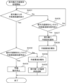
- FIG. 7 is a flowchart showing the refrigerant leak detection process in the air conditioner 1 according to embodiment 2. The refrigerant leak detection process in the air conditioner 1 will be described with reference to FIG. 7.
- step S201 the outdoor control unit 51 determines whether or not there is a refrigerant leakage detection signal from the refrigerant detection sensor 30a. If there is a refrigerant leakage detection signal (Yes in step S201), the process proceeds to step S202.
- the refrigerant detection sensor 30a since the refrigerant detection sensor 30a is positioned near the outside of the outdoor electrical equipment box 16, the refrigerant detection sensor 30a can detect a refrigerant leakage before the leaked refrigerant flows into the outdoor electrical equipment box 16. The case where the result in step S201 is Yes will be explained.
- step S202 the outdoor control unit 51 stops the operation of electronic components having moving parts included in the outdoor control device 50. Stopping the operation means not switching relays, electromagnetic switches, etc. Specifically, the outdoor control unit 51 maintains the current output for switching relays, electromagnetic switches, etc. This prevents the generation of fire inside the outdoor electrical equipment box 16 and the ignition of leaked refrigerant.
- step S203 proceed to step S203.
- step S203 the outdoor control unit 51 notifies the indoor communication unit 63 via the outdoor communication unit 53 that a refrigerant leak has occurred in the outdoor unit 10.
- the outdoor control device 50 has stopped operating electronic components having moving parts, but the outdoor control device 50 as a whole has not stopped, so the outdoor communication unit 53 is still functioning.
- step S204 proceed to step S204.
- step S204 the indoor control unit 61, which has received information about a refrigerant leak in the outdoor unit 10 via the indoor communication unit 63, causes the notification means 24 to notify the user of the refrigerant leak.
- the notification means 24 notifies the user of the refrigerant leak by voice or screen display, etc.
- step S205 proceed to step S205.
- step S205 the indoor control unit 61 controls the indoor power supply circuit 62 to cut off the power supply to the outdoor unit 10. This causes the refrigerant circuit of the air conditioner 1 to stop operating, and the refrigerant leak detection process ends.
- step S201 If there is no refrigerant leak detection signal in step S201, proceed to step S206.
- step S206 the outdoor control unit 51 determines whether or not there is a refrigerant leakage detection signal from the second refrigerant detection sensor 30b. If there is no refrigerant leakage detection signal (No in step S206), the process returns to step S201 again. If there is a refrigerant leakage detection signal from the second refrigerant detection sensor 30b (Yes in step S206), the process proceeds to step S207.
- the second refrigerant detection sensor 30b is disposed at the bottom of the housing 10a of the outdoor unit 10. Flammable refrigerant has a higher density than air and flows downward from the leaked point. Therefore, even if the leaked refrigerant is small, the leaked refrigerant will flow to the bottom of the housing 10a and can be detected by the second refrigerant detection sensor 30b.
- step S207 the outdoor control unit 51 drives the outdoor fan 15.
- Step S207 is the case where there is no refrigerant leakage detection signal from the refrigerant detection sensor 30a, but there is a refrigerant leakage detection signal from the second refrigerant detection sensor 30b.
- the refrigerant does not flow into the outdoor electrical equipment box 16, and is present at the bottom of the housing 10a of the outdoor unit 10.
- the refrigerant that has accumulated at the bottom of the housing 10a can be dispersed outside the housing 10a.
- step S208 proceed to step S208.
- step S208 it is determined whether or not a refrigerant leakage detection signal is present from the second refrigerant detection sensor 30b for a certain period of time. If a refrigerant leakage detection signal is present from the second refrigerant detection sensor 30b (No in step S208), refrigerant remains in the lower part of the housing 10a, so the process returns to step S207 and the outdoor fan 15 continues to be driven. If a refrigerant leakage detection signal is not present from the second refrigerant detection sensor 30b for a certain period of time (Yes in step S208), the refrigerant accumulated in the lower part of the housing 10a has been blown out of the housing 10a. If a refrigerant leakage detection signal is not present from the second refrigerant detection sensor 30b for a certain period of time, the process proceeds to step S203. The processes from step S203 to step S205 are omitted as they have been described above.
- the outdoor unit 10 of the air conditioner 1 of the present disclosure comprises a housing 10a, a compressor 11 arranged within the housing 10a and compressing a flammable refrigerant, an outdoor heat exchanger 13 arranged within the housing 10a and connected to the compressor 11 via a refrigerant piping 40 through which the flammable refrigerant flows and exchanging heat between the flammable refrigerant and air, an outdoor electrical equipment box 16 arranged above the compressor 11 within the housing 10a, a refrigerant detection sensor 30a installed outside the outdoor electrical equipment box 16 and detecting leakage of flammable refrigerant, an outdoor control device 50 arranged inside the outdoor electrical equipment box 16 and composed of multiple electronic components, which stops the operation of electronic components having moving parts among the electronic components when the refrigerant detection sensor 30a detects leakage of flammable refrigerant, and further comprises a second refrigerant detection sensor 30b arranged within the housing 10a below the refrigerant detection sensor 30a for detecting leakage of flammable refriger
- the outdoor unit 10 is further provided with an outdoor fan 15 disposed within the housing 10a and generating an airflow that passes through the outdoor heat exchanger 13, and the outdoor control device 50 drives the outdoor fan 15 when the refrigerant detection sensor 30a does not detect a flammable refrigerant leak and the second refrigerant detection sensor 30b detects a flammable refrigerant leak.
- the outdoor control device 50 drives the outdoor fan 15 when the refrigerant detection sensor 30a does not detect a flammable refrigerant leak and the second refrigerant detection sensor 30b detects a flammable refrigerant leak.
- Fig. 8 is a configuration diagram of an air conditioner 1 according to the third embodiment.
- Fig. 9 is a block diagram showing the functional configuration of an outdoor control device 50 and an indoor control device 60 according to the third embodiment. Note that a description of the same parts of the present embodiment as those of the above-mentioned embodiments will be omitted.
- the outdoor unit 10 of the air conditioner 1 of the present disclosure comprises a housing 10a, a compressor 11 arranged within the housing 10a for compressing a flammable refrigerant, an outdoor heat exchanger 13 arranged within the housing 10a and connected to the compressor 11 via a refrigerant piping 40 through which the flammable refrigerant flows and for exchanging heat between the flammable refrigerant and air, an outdoor electrical equipment box 16 arranged above the compressor 11 within the housing 10a, a refrigerant detection sensor 30a installed on the outside of the outdoor electrical equipment box 16 for detecting leakage of the flammable refrigerant, and a refrigerant detection sensor 30a arranged inside the outdoor electrical equipment box 16 and composed of multiple electronic components, the refrigerant detection sensor 30a detecting the leakage of the flammable refrigerant.
Landscapes
- Engineering & Computer Science (AREA)
- Chemical & Material Sciences (AREA)
- Combustion & Propulsion (AREA)
- Mechanical Engineering (AREA)
- General Engineering & Computer Science (AREA)
- Air Conditioning Control Device (AREA)
Priority Applications (2)
| Application Number | Priority Date | Filing Date | Title |
|---|---|---|---|
| JP2025566148A JPWO2025141852A1 (https=) | 2023-12-28 | 2023-12-28 | |
| PCT/JP2023/047230 WO2025141852A1 (ja) | 2023-12-28 | 2023-12-28 | 空気調和機の室外機、および空気調和機 |
Applications Claiming Priority (1)
| Application Number | Priority Date | Filing Date | Title |
|---|---|---|---|
| PCT/JP2023/047230 WO2025141852A1 (ja) | 2023-12-28 | 2023-12-28 | 空気調和機の室外機、および空気調和機 |
Publications (1)
| Publication Number | Publication Date |
|---|---|
| WO2025141852A1 true WO2025141852A1 (ja) | 2025-07-03 |
Family
ID=96217148
Family Applications (1)
| Application Number | Title | Priority Date | Filing Date |
|---|---|---|---|
| PCT/JP2023/047230 Pending WO2025141852A1 (ja) | 2023-12-28 | 2023-12-28 | 空気調和機の室外機、および空気調和機 |
Country Status (2)
| Country | Link |
|---|---|
| JP (1) | JPWO2025141852A1 (https=) |
| WO (1) | WO2025141852A1 (https=) |
Citations (8)
| Publication number | Priority date | Publication date | Assignee | Title |
|---|---|---|---|---|
| JPH04369370A (ja) * | 1991-06-14 | 1992-12-22 | Hitachi Ltd | 冷凍装置 |
| JP2003157870A (ja) * | 2001-11-22 | 2003-05-30 | Toyota Motor Corp | 電源システムおよび電源システムの制御方法 |
| JP2005241121A (ja) * | 2004-02-26 | 2005-09-08 | Mitsubishi Heavy Ind Ltd | 空気調和機 |
| WO2013145012A1 (ja) * | 2012-03-29 | 2013-10-03 | 三菱電機株式会社 | 室外機及びその室外機を備えた空気調和装置 |
| JP2016070568A (ja) * | 2014-09-29 | 2016-05-09 | 日立アプライアンス株式会社 | 空気調和機の室内機 |
| JP2019095156A (ja) * | 2017-11-27 | 2019-06-20 | 三菱重工サーマルシステムズ株式会社 | 空調機 |
| WO2020144738A1 (ja) * | 2019-01-08 | 2020-07-16 | 三菱電機株式会社 | 空気調和装置 |
| JP2021139581A (ja) * | 2020-03-06 | 2021-09-16 | ダイキン工業株式会社 | 床置き型空調室内機 |
-
2023
- 2023-12-28 WO PCT/JP2023/047230 patent/WO2025141852A1/ja active Pending
- 2023-12-28 JP JP2025566148A patent/JPWO2025141852A1/ja active Pending
Patent Citations (8)
| Publication number | Priority date | Publication date | Assignee | Title |
|---|---|---|---|---|
| JPH04369370A (ja) * | 1991-06-14 | 1992-12-22 | Hitachi Ltd | 冷凍装置 |
| JP2003157870A (ja) * | 2001-11-22 | 2003-05-30 | Toyota Motor Corp | 電源システムおよび電源システムの制御方法 |
| JP2005241121A (ja) * | 2004-02-26 | 2005-09-08 | Mitsubishi Heavy Ind Ltd | 空気調和機 |
| WO2013145012A1 (ja) * | 2012-03-29 | 2013-10-03 | 三菱電機株式会社 | 室外機及びその室外機を備えた空気調和装置 |
| JP2016070568A (ja) * | 2014-09-29 | 2016-05-09 | 日立アプライアンス株式会社 | 空気調和機の室内機 |
| JP2019095156A (ja) * | 2017-11-27 | 2019-06-20 | 三菱重工サーマルシステムズ株式会社 | 空調機 |
| WO2020144738A1 (ja) * | 2019-01-08 | 2020-07-16 | 三菱電機株式会社 | 空気調和装置 |
| JP2021139581A (ja) * | 2020-03-06 | 2021-09-16 | ダイキン工業株式会社 | 床置き型空調室内機 |
Also Published As
| Publication number | Publication date |
|---|---|
| JPWO2025141852A1 (https=) | 2025-07-03 |
Similar Documents
| Publication | Publication Date | Title |
|---|---|---|
| JP6168113B2 (ja) | 空調室内機 | |
| CN112105876B (zh) | 制冷剂泄漏判定装置、空调机以及制冷剂泄漏判定方法 | |
| CN110402360B (zh) | 冷冻装置的室内单元 | |
| JP6477767B2 (ja) | 冷凍装置 | |
| JP6143977B1 (ja) | 冷凍サイクル装置及び冷凍サイクルシステム | |
| CN107429957B (zh) | 制冷循环装置以及制冷循环系统 | |
| CN107110541B (zh) | 空调机 | |
| CN212457182U (zh) | 空调机 | |
| JP6121075B1 (ja) | 冷凍サイクル装置 | |
| WO2019239556A1 (ja) | 空気調和装置 | |
| WO2020021661A1 (ja) | 空調システム | |
| JP5892199B2 (ja) | 空調室内機 | |
| JP6656406B2 (ja) | 空気調和装置および冷媒漏洩検知方法 | |
| JP6157789B1 (ja) | 冷凍サイクル装置及び冷媒漏洩検知方法 | |
| JP7484082B2 (ja) | 空気調和機 | |
| JP2016070594A (ja) | 空気調和装置 | |
| JPWO2017187562A1 (ja) | 冷凍サイクル装置 | |
| WO2019038797A1 (ja) | 空気調和装置および膨張弁ユニット | |
| JP2002061996A (ja) | 空気調和機 | |
| EP4160101A1 (en) | A ventilation system for a room | |
| JP2020034250A (ja) | 冷凍サイクル装置 | |
| JP2014137161A (ja) | 空気調和装置 | |
| WO2025141852A1 (ja) | 空気調和機の室外機、および空気調和機 | |
| JP2016166680A (ja) | 空気調和装置 | |
| JP2022024290A (ja) | 空気調和機 |
Legal Events
| Date | Code | Title | Description |
|---|---|---|---|
| 121 | Ep: the epo has been informed by wipo that ep was designated in this application |
Ref document number: 23963198 Country of ref document: EP Kind code of ref document: A1 |
|
| ENP | Entry into the national phase |
Ref document number: 2025566148 Country of ref document: JP Kind code of ref document: A |
|
| WWE | Wipo information: entry into national phase |
Ref document number: 2025566148 Country of ref document: JP |