WO2025115138A1 - ロータおよび永久磁石モータ - Google Patents
ロータおよび永久磁石モータ Download PDFInfo
- Publication number
- WO2025115138A1 WO2025115138A1 PCT/JP2023/042782 JP2023042782W WO2025115138A1 WO 2025115138 A1 WO2025115138 A1 WO 2025115138A1 JP 2023042782 W JP2023042782 W JP 2023042782W WO 2025115138 A1 WO2025115138 A1 WO 2025115138A1
- Authority
- WO
- WIPO (PCT)
- Prior art keywords
- bonded magnet
- rotor
- ferrite particles
- hard magnetic
- magnetic ferrite
- Prior art date
- Legal status (The legal status is an assumption and is not a legal conclusion. Google has not performed a legal analysis and makes no representation as to the accuracy of the status listed.)
- Pending
Links
Images


Classifications
-
- H—ELECTRICITY
- H02—GENERATION; CONVERSION OR DISTRIBUTION OF ELECTRIC POWER
- H02K—DYNAMO-ELECTRIC MACHINES
- H02K1/00—Details of the magnetic circuit
- H02K1/06—Details of the magnetic circuit characterised by the shape, form or construction
- H02K1/22—Rotating parts of the magnetic circuit
- H02K1/27—Rotor cores with permanent magnets
- H02K1/2706—Inner rotors
- H02K1/272—Inner rotors the magnetisation axis of the magnets being perpendicular to the rotor axis
- H02K1/274—Inner rotors the magnetisation axis of the magnets being perpendicular to the rotor axis the rotor consisting of two or more circumferentially positioned magnets
- H02K1/2753—Inner rotors the magnetisation axis of the magnets being perpendicular to the rotor axis the rotor consisting of two or more circumferentially positioned magnets the rotor consisting of magnets or groups of magnets arranged with alternating polarity
- H02K1/276—Magnets embedded in the magnetic core, e.g. interior permanent magnets [IPM]
Definitions
- This disclosure relates to a rotor with permanent magnets and a permanent magnet motor.
- a known configuration for permanent magnet motors is to use a bonded magnet made of hard magnetic powder and resin for the rotating body of the rotor.
- Such permanent magnet motors are widely used in motor equipment such as blowers and ventilation fans.
- a potential difference known as axial voltage occurs between the inside and outside of the bearing that supports the rotor, and if this potential difference becomes excessive, a small current flows inside the bearing, causing electrolytic corrosion in the bearing. If this electrolytic corrosion progresses, it can lead to malfunctions such as abnormal noises coming from the bearing, so a solution was needed.
- Patent Document 1 discloses an electric motor that includes a stator, a rotor in which a rotating body made of a resin magnet and a shaft are integrally formed, a bearing, and a conductive bracket, and in which the capacitance between the shaft and the outer periphery of the rotating body is 3 pF or more and 12 pF or less when the measurement frequency is 10 kHz.
- the present disclosure has been made in consideration of the above, and aims to obtain a rotor that can suppress the variation in capacitance that causes electrolytic corrosion more than ever before.
- the rotor according to the present disclosure includes a shaft and a rotating body fixed to the shaft, the bonded magnet having hard magnetic ferrite particles with a volume resistivity of 10 8 ⁇ cm or more and a resin.
- the dielectric loss between the inner and outer peripheral surfaces of the bonded magnet in the rotating body is 70 or less.
- the rotor disclosed herein has the advantage of being able to suppress the variation in capacitance that causes electrolytic corrosion more effectively than ever before.
- FIG. 1 is a cross-sectional view showing a schematic example of a rotor according to a first embodiment
- FIG. 1 is a schematic diagram showing an example of the configuration of a typical bonded magnet.
- FIG. 1 is a schematic diagram showing an example of the configuration of a typical bonded magnet.
- FIG. 2 is a schematic diagram showing an example of the structure of hard magnetic ferrite particles contained in the bonded magnet of the rotor according to the first embodiment;
- FIG. 2 is a schematic diagram showing an example of the polar anisotropic orientation of hard magnetic ferrite particles inside the bonded magnet of the rotor according to the first embodiment;
- FIG. 1 is a diagram showing an example of the relationship between the magnetization easy axis and the magnetization direction of hard magnetic ferrite particles.
- FIG. 1 is a cross-sectional view showing a schematic example of a rotor according to a first embodiment
- FIG. 1 is a schematic diagram showing an example of the configuration of a typical bonded magnet.
- FIG. 1 is a diagram showing an example of the relationship between the magnetization easy axis and the magnetization direction of hard magnetic ferrite particles.
- FIG. 1 is a diagram showing an example of the relationship between the magnetization easy axis and the magnetization direction of hard magnetic ferrite particles.
- FIG. 2 is a schematic diagram showing an example of polar anisotropic magnetization of a bonded magnet used in a rotor according to the first embodiment;
- FIG. 1 is a cross-sectional view showing a schematic example of a structure of a rotor according to a first embodiment; A flowchart showing an example of a procedure for a manufacturing method of a rotor according to the first embodiment.
- FIG. 11 is a cross-sectional view showing a schematic example of a configuration of a permanent magnet motor according to a second embodiment.
- Fig. 1 is a cross-sectional view showing a schematic example of a rotor according to embodiment 1.
- the rotor 1 according to embodiment 1 has a shaft 2 and a rotor 3 fixed to the shaft 2.
- the rotor 3 includes a bonded magnet 4.
- the rotor 3 is made of the bonded magnet 4.
- the bonded magnet 4 has a configuration in which hard magnetic ferrite particles 6, which are hard magnetic particles, are dispersed in a resin 5.
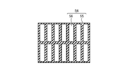
- FIG. 2 and 3 are schematic diagrams showing an example of the configuration of a typical bonded magnet.
- FIG. 2 shows an example of the configuration of a bonded magnet 54 immediately after molding
- FIG. 3 shows an example of the configuration of a bonded magnet 54 after some time has passed since molding.
- a bonded magnet 54 is formed by bonding hard magnetic particles 56 with a binder component made of resin 55.
- the filling amount of the hard magnetic particles 56 is often relatively high.
- the hard magnetic particles 56 are tightly adhered to each other due to the binding force of the binder component resin 55, as shown in FIG. 2.
- the binding force of the resin 55 loosens slightly due to the springback phenomenon.
- FIG. 2 shows an example of the configuration of a bonded magnet 54 immediately after molding
- FIG. 3 shows an example of the configuration of a bonded magnet 54 after some time has passed since molding.
- a bonded magnet 54 is formed by bonding hard magnetic particles 56 with a binder component made of resin 55.
- the distance between the hard magnetic particles 56 may become greater than that shown in FIG. 2 immediately after molding.
- the volume resistivity of the hard magnetic particles 56 contained in the bonded magnet 54 is low, this will cause variation in the electrical performance of the bonded magnet 54. If the volume resistivity of the hard magnetic particles 56 is low, it will be particularly prone to variation in the dielectric properties, which is a factor in the fluctuation of the electrostatic capacitance that causes electrolytic corrosion in motor equipment.
- the volume resistivity of the hard magnetic particles 56 is low.
- a conductive path is formed within the bonded magnet 54, making it easier for electricity to flow.
- the dielectric loss of the bonded magnet 54 increases and the dielectric constant shows a high value.
- the conductive path within the bonded magnet 54 becomes fewer and the characteristics become like an insulator. As a result, the electrical conductivity becomes lower than in the case of FIG.
- the dielectric loss within the bonded magnet 54 decreases, and the dielectric constant becomes lower.
- the dielectric characteristics i.e., the dielectric constant and dielectric loss, vary depending on the distance between the hard magnetic particles 56.
- the electrostatic capacitance varies, inducing electrolytic corrosion.
- the volume resistivity of the hard magnetic particles 56 is the cause of the variation in capacitance in the bonded magnet 54.
- insulating hard magnetic particles are used in the bonded magnet 4 used in the rotor 1 according to the first embodiment.
- an example of the insulating hard magnetic particles is the insulating hard magnetic ferrite particles 6 having a volume resistivity of 10 8 ⁇ cm or more.
- the dielectric loss of the bonded magnet 4 is a low value of 70 or less.
- the hard magnetic ferrite particles 6 contained in the bonded magnet 4 of the rotor 1 according to the first embodiment may be a ferromagnetic material having spontaneous magnetization and a volume resistivity equal to or greater than the value at which the material is considered to be an insulator.
- Examples of such hard magnetic ferrite particles 6 include M-type hexagonal ferrites such as BaFe 12 O 19 and SrFe 12 O 19 , W-type hexagonal ferrites such as BaFe 18 O 27 and SrFe 18 O 27 , Z-type hexagonal ferrites such as Ba 3 Co 2 Fe 24 O 41 and Sr 3 Co 2 Fe 24 O 41 , and Y-type hexagonal ferrites such as BaZnFe 12 O 22.
- M-type hexagonal ferrites are also called magnetoplumbite-type hexagonal ferrites. These may be used alone or in combination of two or more. Among these, M-type hexagonal ferrite is particularly suitable because it is widely available and inexpensive. Furthermore, it is also possible to use hexagonal ferrite having a composition in which a part of the metal element Ba, Sr or Fe in the above hexagonal ferrite is replaced with a transition metal element.
- FIG. 4 is a diagram showing a schematic example of the structure of hard magnetic ferrite particles contained in the bonded magnet of the rotor according to the first embodiment.
- the hard magnetic ferrite particles 6 contained in the bonded magnet 4 of the rotor 1 according to the first embodiment are hexagonal crystals, and have a plate-like particle shape as shown in FIG. 4.
- These hard magnetic ferrite particles 6 have the characteristic that they grow in crystal form such that the c-plane, which is a plane perpendicular to the c-axis of the hexagonal crystal structure, becomes the long plane of the plate-like particle.
- the aspect ratio of the long and short diameters of the plate-like particle tends to increase as the crystal grows.
- the direction perpendicular to the c-plane is the c-axis, which is the crystal axis, and the a-axis or b-axis, which is the crystal axis, exists within the plane perpendicular to the c-axis, i.e., within the c-plane.
- the hard magnetic ferrite particles 6 contained in the bonded magnet 4 of the rotor 1 according to the first embodiment preferably include first hard magnetic ferrite particles having an average particle size of 3 ⁇ m or more and 8 ⁇ m or less and an aspect ratio of 1.5 to 3 or less, and second hard magnetic ferrite particles having an average particle size of 0.05 ⁇ m or more and 1 ⁇ m or less.
- the content of the second hard magnetic ferrite particles is preferably 5% by mass or more and 40% by mass or less, and more preferably 10% by mass or more and 30% by mass or less. When the content of the second hard magnetic ferrite particles is less than 5% by mass, it is easy to control the orientation in the entire bonded magnet 4, but it is difficult to achieve high packing.
- the content of the second hard magnetic ferrite particles is more than 40% by mass, it is possible to achieve high packing of the first hard magnetic ferrite particles, but since the content of the first hard magnetic ferrite particles is relatively small, the orientation in the entire bonded magnet 4 is deteriorated and the desired magnetic force cannot be obtained. For this reason, it is desirable for the content of the second hard magnetic ferrite particles to be 5% by mass or more and 40% by mass or less.
- the average particle size of the hard magnetic ferrite particles 6 is determined by measuring the particle size of the hard magnetic ferrite particles 6 filled in the bonded magnet 4. Specifically, the bonded magnet 4 is heat-treated and incinerated in an air atmosphere at a temperature of 500°C to 800°C for a period of about 5 to 10 hours using an electric furnace to obtain hard magnetic ferrite particles 6. The average particle size of the hard magnetic ferrite particles 6 can be determined by measuring the particle size distribution of this sample using a laser diffraction/scattering method. The average particle size of the hard magnetic ferrite particles 6 determined at this time is the diameter of a volume-equivalent sphere.
- the volume resistivity of the hard magnetic ferrite particles 6 contained in the bonded magnet 4 of the rotor 1 according to the first embodiment is preferably 10 8 ⁇ cm or more in terms of suppressing the variation in the capacitance of the bonded magnet 4.
- the volume resistivity of the hard magnetic ferrite particles 6 is more preferably 10 9 ⁇ cm or more, and even more preferably 10 10 ⁇ cm or more. If the volume resistivity of the hard magnetic ferrite particles 6 is less than 10 8 ⁇ cm, the hard magnetic ferrite particles 6 have more semiconductive properties than insulators. For this reason, as shown in FIG. 2 and FIG.
- the hard magnetic ferrite particles 6 used in the rotor 1 according to the first embodiment have a volume resistivity of 10 8 ⁇ cm or more, which is a value that can be considered as an insulator, so that the electrical properties are less likely to vary even if the distance between the hard magnetic ferrite particles 6 in the bonded magnet 4 varies.
- the volume resistivity of the hard magnetic ferrite particles 6 is determined by measuring the volume resistivity of the hard magnetic ferrite particles 6 filled in the bonded magnet 4.
- the bonded magnet 4 is heat-treated and incinerated in an air atmosphere at a temperature of 500° C. to 800° C. for a period of about 5 hours to 10 hours using an electric furnace to obtain hard magnetic ferrite particles 6.
- the volume resistivity of the hard magnetic ferrite particles 6 can be determined by measuring this sample with a powder resistance measuring device.
- the orientation of the hard magnetic ferrite particles 6 in the bonded magnet 4 of the rotor 1 according to embodiment 1 may be non-oriented or oriented. When oriented, the orientation may be radial, axial, radial, or polar anisotropic.
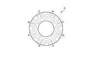
- Figure 5 is a schematic diagram showing an example of polar anisotropic orientation of the hard magnetic ferrite particles inside the bonded magnet of the rotor according to embodiment 1. When oriented, it is preferable that the c-plane of the hard magnetic ferrite particles 6 be polar anisotropically oriented as shown in Figure 5, from the viewpoint of improving the demagnetization resistance of the bonded magnet 4 and obtaining a strong magnetic force.
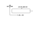
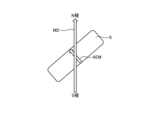
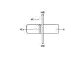
- FIGS. 6 to 8 are diagrams showing an example of the relationship between the magnetization easy axis and the magnetization direction of hard magnetic ferrite particles.
- the magnetization form of the bonded magnet 4 is preferably magnetized in a direction perpendicular to the c-plane, i.e., in the direction of the magnetization easy axis AEM, along the orientation of the hard magnetic ferrite particles 6.
- FIG. 6 and FIG. 7 if the direction of the magnetization easy axis AEM of the hard magnetic ferrite particles 6 does not match the magnetization direction MD, the magnetic force is difficult to improve. In the case of FIG.
- the direction of the magnetization easy axis AEM is inclined by 90° to the magnetization direction MD, and magnetization in the direction of the magnetization easy axis AEM is not possible.
- the direction of the magnetization easy axis AEM intersects with the magnetization direction MD at an angle greater than 0° and less than 90°, and although not as difficult as in the case of FIG. 6, it is difficult to magnetize in the direction of the magnetization easy axis AEM, and it is difficult to improve the magnetic force.
- the rotating body 3 of the rotor 1 includes a bonded magnet 4.
- the structure of the rotating body 3 may be a surface magnet type in which the bonded magnet 4 is attached in a ring shape to the outer circumferential surface of the rotor component, or an embedded magnet type in which the bonded magnet 4 is embedded inside the rotor component.
- the bonded magnet 4 may be a ring magnet in which a ring-shaped bonded magnet 4 is attached to the outer surface of the rotor component so as to cover the outer surface of the ring-shaped rotor component, or an arc magnet in which an arc-shaped bonded magnet 4 is attached along the outer surface of the ring-shaped rotor component.
- the outer and inner circumferential surfaces of the bonded magnet 4 may be circular, elliptical, wavy, or other shapes.
- bonded magnets 4 of various shapes such as arc magnets in which arc-shaped bonded magnets 4 are embedded inside the rotor component, and flat magnets in which flat bonded magnets 4 are embedded inside the rotor component can be used.
- the bond magnet 4 of the rotor 1 has a dielectric loss of 70 or less, preferably 50 or less, and more preferably 30 or less. If the volume resistivity of the hard magnetic ferrite particles 6 contained in the bond magnet 4 is lower than the value considered to be an insulator, the hard magnetic ferrite particles 6 are connected to each other within the bond magnet 4, forming a conductive path and lowering the volume resistivity of the bond magnet 4. That is, the electrical conductivity of the bond magnet 4 increases. In this case, the dielectric loss of the bond magnet 4 increases significantly, causing the dielectric constant of the bond magnet 4 to increase. Such an increase in the dielectric constant causes electrolytic corrosion in a permanent magnet motor having the rotor 1.
- the bond magnet 4 of the rotor 1 according to the first embodiment contains hard magnetic ferrite particles 6 whose volume resistivity is equal to or higher than the value at which the bond magnet 4 becomes an insulator, so that a conductive path is unlikely to be generated inside the bond magnet 4 and the dielectric loss is suppressed to a low value.
- the increase in the dielectric constant is also suppressed, making it possible to suppress the occurrence of electrolytic corrosion in a permanent magnet motor having the rotor 1.
- the dielectric loss and relative dielectric constant of the bonded magnet 4 refer to values calculated from the capacitance C and dielectric tangent tan ⁇ measured between the inner and outer circumferential surfaces of the bonded magnet 4 in the rotating body 3 using the following formulas (1) and (2):
- Relative permittivity C ⁇ ln(b/a) ⁇ (2 ⁇ 0 ) (1)
- Dielectric loss tan ⁇ ⁇ relative dielectric constant (2)
- a is the radius from the center of shaft 2 to the inner peripheral surface of bonded magnet 4
- b is the radius from the center of shaft 2 to the outer peripheral surface of bonded magnet 4
- ⁇ 0 is the dielectric constant of a vacuum.
- the content of hard magnetic ferrite particles 6 in the bonded magnet 4 of the rotor 1 according to the first embodiment is preferably 70 wt% or more and 95 wt% or less.
- the content of hard magnetic ferrite particles 6 is 75 wt% or more and 90 wt% or less, it is preferable because the hard magnetic ferrite particles 6 are easily mixed and dispersed in the resin 5, workability and moldability are good, and the magnetic force of the bonded magnet 4 is also good. If the content of hard magnetic ferrite particles 6 is less than 70 wt%, a bonded magnet 4 having the desired magnetic force may not be obtained. On the other hand, if the content of hard magnetic ferrite particles 6 exceeds 95 wt%, it becomes difficult to mix and disperse the hard magnetic ferrite particles 6 in the resin 5, which may cause problems in workability and moldability.
- the resin 5 used in the bonded magnet 4 of the rotor 1 according to the first embodiment can be a thermosetting resin or a thermoplastic resin.
- thermoplastic resins are preferred from the viewpoint of moldability.
- thermoplastic resins include polymers or copolymers of at least one monomer selected from the group consisting of ethylene, propylene, butadiene, isoprene, styrene, methacrylic acid, acrylic acid, methacrylic acid esters, acrylic acid esters, vinyl chloride, tetrafluoroethylene, acrylonitrile, maleic anhydride, and vinyl acetate, as well as at least one resin selected from the group consisting of polyphenylene ether, chlorinated polyethylene, silicone resin, polyamide, polyimide, polycarbonate, polyester, polyacetal, polyphenylene sulfide, polyethylene glycol, polyetherimide, polyketone, polyether ether ketone, polyether sulfone, and polyarylate.
- additives such as
- the size of the bonded magnet 4 used in the rotor 1 according to the first embodiment may be changed as appropriate depending on the application.
- the shaft 2 used in the rotor 1 according to the first embodiment is not particularly limited, but is preferably a metal or alloy from the viewpoint of durability and cost.
- metals that can be used for the shaft 2 include iron, stainless steel, aluminum, and copper.
- the rotor 1 according to the first embodiment is equipped with a bonded magnet 4 that can suppress the variation in electrostatic capacitance that causes electrolytic corrosion.
- FIG. 11 is a flow chart showing an example of the procedure of the method for manufacturing the rotor according to the first embodiment.
- the thermoplastic resin as the resin 5 is heated and melted (step S11).
- the hard magnetic ferrite particles 6 having a volume resistivity of 10 8 ⁇ cm or more are mixed and dispersed in the heated and melted thermoplastic resin to prepare a resin composition (step S12).
- the mixing method for preparing the resin composition is not particularly limited, and can be performed according to a method known in the art.
- a single-screw extruder or a multi-screw extruder is generally used, but in addition to the above extruders, a Banbury mixer, a roller, a co-kneader, a blast mill, a Prabender blastograph, etc. can also be used. Then, the resin composition can be prepared by operating these in a batch or continuous manner. In addition, it is also possible to carry out so-called mold blending, in which the thermoplastic resin pellets and the hard magnetic ferrite particles 6 are mixed to form a mixture material without melt kneading, and the mixture material is used as a molding resin and melt kneaded in the molding machine heating cylinder.
- the prepared resin composition is heated and melted at a temperature at which the thermoplastic resin melts, and a bonded magnet 4 is formed by molding into a specified shape (step S13).
- the shape may be any shape suitable for use as the bonded magnet 4 for the rotor 1, and is preferably a block shape.
- a crushing process step for crushing the prepared resin composition can be provided before the resin composition is heated and melted in step S13. It is preferable to subject the prepared resin composition to a crushing process, since this can improve the workability of the heat melting process.
- molding methods include injection molding and uniaxial press molding.
- a magnetic field orientation permanent magnet and a magnetic field orientation yoke can be arranged in the mold so as to form a polar anisotropic orientation magnetic field of similar shape in the circumferential direction. This preferably orients the hard magnetic ferrite particles 6 during molding. Furthermore, when molding the bonded magnet 4, the shaft 2 can be set in the mold and molded as a single unit. In this way, molding the shaft 2 and the bonded magnet 4 as a single unit is preferable from the viewpoint of productivity.
- a magnetizing device is used to apply a magnetic field with a strength that reaches the saturation point of the maximum magnetic flux density of the hard magnetic ferrite particles 6, thereby magnetizing the bonded magnet 4 molded into the specified shape (step S14).
- a magnetizing device is used to apply a magnetic field with a strength that reaches the saturation point of the maximum magnetic flux density of the hard magnetic ferrite particles 6, thereby magnetizing the bonded magnet 4 molded into the specified shape (step S14).
- the method for magnetizing the bonded magnet 4 includes a static magnetic field generation method using a DC electromagnet, and a pulsed magnetic field generation method using a capacitor-type magnetizer.
- the rotor 1 comprises a shaft 2 and a rotating body 3 including a bonded magnet 4 and fixed to the shaft 2, the bonded magnet 4 comprises hard magnetic ferrite particles 6 having a volume resistivity of 10 8 ⁇ cm or more and a resin 5, and the dielectric loss of the bonded magnet 4 is 70 or less.
- the bonded magnet 4 has insulating properties both immediately after molding of the bonded magnet 4 and after the springback phenomenon has occurred over time since molding, so that a conductive path is unlikely to be generated inside the bonded magnet 4.
- the filling amount of the hard magnetic ferrite particles 6 in the bonded magnet 4 is 70 wt% or more and 95 wt% or less. This has the effect of making it easier to mix and disperse the hard magnetic ferrite particles 6 in the resin 5, improving workability and moldability, and also improving the magnetic force of the bonded magnet 4.
- the hard magnetic ferrite particles 6 contained in the bonded magnet 4 include first hard magnetic ferrite particles having an average particle size of 3 ⁇ m or more and 8 ⁇ m or less and an aspect ratio of 1.5 to 3 or less, and second hard magnetic ferrite particles having an average particle size of 0.05 ⁇ m or more and 1 ⁇ m or less. This has the effect of making it easier to control the orientation throughout the bonded magnet 4, while enabling high packing without significantly increasing the pressure during molding, and making it possible to obtain a bonded magnet 4 with the desired magnetic force.
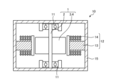
- FIG. 12 is a cross-sectional view showing a schematic example of the configuration of a permanent magnet motor according to embodiment 2.
- a permanent magnet motor 10 according to embodiment 2 will be described below with reference to Fig. 12.
- Permanent magnet motor 10 according to embodiment 2 includes rotor 1 having rotating body 3 including bonded magnet 4 fixed to shaft 2, two bearings 11 arranged on both sides of bonded magnet 4 in the extension direction of shaft 2 and supporting shaft 2 of rotor 1, stator 12 having winding coil 14 wound around stator core 13, and conductive housing 15.
- Rotor 1 has the configuration described in embodiment 1.
- the permanent magnet motor 10 becomes an electromagnet when an alternating current flows through the winding coils 14 of the stator 12. At this time, the south and north poles of the magnetic field generated at regular intervals by the winding coils 14 wound around each stator core 13 alternate. This generates a magnetic repulsive force with the bonded magnets 4 of the rotor 1, causing the rotating body 3 of the rotor 1 to rotate at high speed, functioning as a motor.
- the permanent magnet motor 10 uses a rotor 1 equipped with a bonded magnet 4 with low dielectric loss and dielectric constant as described in the first embodiment. This makes the capacitance between the bonded magnet 4 of the rotor 1 and the winding coil 14 relatively small, and makes the capacitance between the shaft 2 and the bearing 11 relatively large. This reduces the voltage distribution between the shaft 2 and the bearing 11. In other words, the axial voltage generated between the shaft 2 and the bearing 11 is kept below the discharge start voltage. This makes it possible to suppress the occurrence of electrolytic corrosion in the bearing 11.
- the permanent magnet motor 10 includes the rotor 1 described in the first embodiment, the bearing 11 supporting the shaft 2 of the rotor 1, and the stator 12.
- the rotor 1 includes the bonded magnet 4 having a small dielectric loss and dielectric constant as described in the first embodiment. Since the capacitance between the bonded magnet 4 and the winding coil 14 is relatively small and the capacitance between the shaft 2 and the bearing 11 is relatively large, the voltage distribution between the shaft 2 and the bearing 11 is small. In other words, the axial voltage generated between the shaft 2 and the bearing 11 is suppressed to less than the discharge start voltage. As a result, it has the effect of being able to provide a permanent magnet motor 10 capable of suppressing the occurrence of electrolytic corrosion in the bearing 11.
- the hard magnetic ferrite particles 6 used in the following examples and comparative examples are manufactured by crushing a bulk of hard magnetic ferrite using a known method such as coarse crushing with an Attritor (registered trademark) and fine crushing with a ball mill. For various hard magnetic ferrite particles 6 manufactured under different crushing conditions, the particle size distribution is measured by a laser diffraction/scattering method, and the content of fine particles of 0.05 ⁇ m or more and 1 ⁇ m or less is calculated. Table 1 shows the characteristics of the manufactured hard magnetic ferrite particles.
- the material of the hard magnetic ferrite particles 6 is M-type hexagonal ferrite (BaFe 12 O 19 ).
- Table 2 shows the manufacturing conditions and characteristic evaluation results of the bonded magnets according to the examples and comparative examples.
- Example 1 In Example 1, 900 parts by mass of M-type hexagonal ferrite particles No. A, which are hard magnetic ferrite particles 6, are added to 100 parts by mass of chlorinated polyethylene resin, which is resin 5, and mixed at a temperature of 180°C to obtain a resin composition. Next, this resin composition is injection molded using a mold at a molding pressure of 5 MPa so as to be integrated with the shaft 2 to obtain a bonded magnet 4. At this time, the M-type hexagonal ferrite particles are polar anisotropically oriented by magnetic field orientation. After that, the molded bonded magnet 4 is demagnetized once, and then polar anisotropically magnetized using a magnetizing device to obtain a rotor 1 for evaluation. The content of fine particles of the M-type hexagonal ferrite particles No. A is 30 wt%, and the volume resistivity is 10 8 ⁇ cm. The dielectric loss of the bonded magnet 4 obtained in this manner is 68.
- Example 2 A rotor 1 for evaluation is obtained in the same manner as in Example 1, except that the M-type hexagonal ferrite particles of No. B are used instead of the M-type hexagonal ferrite particles of No. A.
- the fine particle content of the M-type hexagonal ferrite particles of No. B is 30 wt %, and the volume resistivity is 10 9 ⁇ cm.
- the dielectric loss of the bonded magnet 4 obtained in this manner is 50.
- Example 3 A rotor 1 for evaluation is obtained in the same manner as in Example 1, except that the M-type hexagonal ferrite particles No. C are used instead of the M-type hexagonal ferrite particles No. A.
- the fine particle content of the M-type hexagonal ferrite particles No. C is 30 wt %, and the volume resistivity is 10 10 ⁇ cm.
- the dielectric loss of the bonded magnet 4 obtained in this manner is 30.
- Example 4 A rotor 1 for evaluation is obtained in the same manner as in Example 1, except that the M-type hexagonal ferrite particles of No. E are used instead of the M-type hexagonal ferrite particles of No. A.
- the fine particle content of the M-type hexagonal ferrite particles of No. E is 4 wt %, and the volume resistivity is 10 8 ⁇ cm.
- the dielectric loss of the bonded magnet 4 obtained in this manner is 58.
- Example 5 A rotor 1 for evaluation is obtained in the same manner as in Example 1, except that the M-type hexagonal ferrite particles of No. F are used instead of the M-type hexagonal ferrite particles of No. A.
- the fine particle content of the M-type hexagonal ferrite particles of No. F is 10 wt %, and the volume resistivity is 10 8 ⁇ cm.
- the dielectric loss of the bonded magnet 4 obtained in this manner is 64.
- Example 6 A rotor 1 for evaluation is obtained in the same manner as in Example 1, except that the M-type hexagonal ferrite particles No. G are used instead of the M-type hexagonal ferrite particles No. A.
- the fine particle content of the M-type hexagonal ferrite particles No. G is 42 wt %, and the volume resistivity is 10 8 ⁇ cm.
- the dielectric loss of the bonded magnet 4 obtained in this manner is 70.
- Example 7 A rotor 1 for evaluation is obtained in the same manner as in Example 1, except that the M-type hexagonal ferrite particles are radially oriented by magnetic field orientation. The dielectric loss of the bonded magnet 4 thus obtained is 68.
- Example 8 A rotor 1 for evaluation is obtained in the same manner as in Example 1, except that radial magnetization is performed using a magnetizing device. The dielectric loss of the bonded magnet 4 thus obtained is 68.
- a rotor 1 for evaluation is obtained in the same manner as in Example 1, except that the M-type hexagonal ferrite particles of No. D are used instead of the M-type hexagonal ferrite particles of No. A.
- the fine particle content of the M-type hexagonal ferrite particles of No. D is 30 wt %, and the volume resistivity is 10 6 ⁇ cm.
- the dielectric loss of the bonded magnet 4 obtained in this manner is 100.
- Example 2 A rotor 1 for evaluation is obtained in the same manner as in Example 1, except that the molding pressure during injection molding is changed to 50 MPa. The dielectric loss of the bonded magnet 4 thus obtained is 75.
- the ratio of the magnetic flux density of the bonded magnet 4 is evaluated for the rotors 1 obtained in the above examples and comparative examples. Specifically, the ratio of the magnetic flux density of the bonded magnet 4 is evaluated by using the magnetic flux density of Example 1 as a reference to determine the magnetic flux density obtained in each example and each comparative example. In other words, the ratio of the magnetic flux density of the bonded magnet 4 is calculated by dividing the magnetic flux density obtained in each example and each comparative example by the magnetic flux density of Example 1. In addition, each of the obtained rotors 1 is incorporated into a permanent magnet motor 10 for evaluation, and the ratio of the axial voltage between the shaft 2 and the bearing 11 is evaluated, and further, the presence or absence of electrolytic corrosion in the bearing 11 of the permanent magnet motor 10 is visually evaluated.
- the ratio of the axial voltage between the shaft 2 and the bearing 11 is evaluated by using the axial voltage of Example 1 as a reference to determine the axial voltage obtained in each example and each comparative example. In other words, the ratio of the axial voltage between the shaft 2 and the bearing 11 is calculated by dividing the axial voltage obtained in each example and each comparative example by the axial voltage of Example 1.
- Example 2 As shown in Table 2, in Examples 1 to 8, which are filled with hard magnetic ferrite particles 6 with a volume resistivity of 108 ⁇ cm or more and in which the dielectric loss of the bonded magnet 4 is 70 or less, the axial voltage generated between the shaft 2 and the bearing 11 is low, and the occurrence of electrolytic corrosion is suppressed.
- Example 2 or Example 3 in which the volume resistivity of the hard magnetic ferrite particles 6 is high at 109 ⁇ cm or 1010 ⁇ cm, the axial voltage is suppressed even lower, and it can be seen that the higher the volume resistivity, the greater the effect of suppressing the occurrence of electrolytic corrosion.
- Example 1 Regarding the orientation of the hard magnetic ferrite particles 6 and the magnetization of the bonded magnet 4, a comparison of Example 1 with Examples 7 and 8, which use the same hard magnetic ferrite particles 6, shows that polar anisotropic orientation and polar anisotropic magnetization improves the magnetic force.
- Comparative Example 1 which was filled with hard magnetic ferrite particles 6 with a volume resistivity of 106 ⁇ cm, which is lower than the value of 108 ⁇ cm considered to be an insulator, the axial voltage generated between the shaft 2 and the bearing 11 was higher than in Example 1, indicating that electrolytic corrosion was occurring. Furthermore, it was found that even when filled with hard magnetic ferrite particles 6 with a volume resistivity equal to or higher than the value considered to be an insulator, as in Comparative Example 2, electrolytic corrosion occurred if the dielectric loss of the bonded magnet 4 was high. This is thought to be due to the fact that the conductive paths due to the connections between the hard magnetic ferrite particles 6 were increased by increasing the molding pressure significantly.
Landscapes
- Engineering & Computer Science (AREA)
- Power Engineering (AREA)
- Permanent Field Magnets Of Synchronous Machinery (AREA)
Priority Applications (2)
| Application Number | Priority Date | Filing Date | Title |
|---|---|---|---|
| PCT/JP2023/042782 WO2025115138A1 (ja) | 2023-11-29 | 2023-11-29 | ロータおよび永久磁石モータ |
| JP2024519459A JP7531751B1 (ja) | 2023-11-29 | 2023-11-29 | ロータおよび永久磁石モータ |
Applications Claiming Priority (1)
| Application Number | Priority Date | Filing Date | Title |
|---|---|---|---|
| PCT/JP2023/042782 WO2025115138A1 (ja) | 2023-11-29 | 2023-11-29 | ロータおよび永久磁石モータ |
Publications (1)
| Publication Number | Publication Date |
|---|---|
| WO2025115138A1 true WO2025115138A1 (ja) | 2025-06-05 |
Family
ID=92174315
Family Applications (1)
| Application Number | Title | Priority Date | Filing Date |
|---|---|---|---|
| PCT/JP2023/042782 Pending WO2025115138A1 (ja) | 2023-11-29 | 2023-11-29 | ロータおよび永久磁石モータ |
Country Status (2)
| Country | Link |
|---|---|
| JP (1) | JP7531751B1 (https=) |
| WO (1) | WO2025115138A1 (https=) |
Citations (5)
| Publication number | Priority date | Publication date | Assignee | Title |
|---|---|---|---|---|
| JP2001068321A (ja) * | 1997-02-25 | 2001-03-16 | Tdk Corp | 酸化物磁性材料、フェライト粒子、焼結磁石、ボンディッド磁石、磁気記録媒体およびモータ |
| WO2019198304A1 (ja) * | 2018-04-10 | 2019-10-17 | パウダーテック株式会社 | フェライト粒子、電子写真現像剤用キャリア芯材、電子写真現像剤用フェライトキャリア及び電子写真現像剤 |
| WO2023053199A1 (ja) * | 2021-09-28 | 2023-04-06 | 三菱電機株式会社 | 電動機、送風機および換気扇 |
| WO2023120184A1 (ja) * | 2021-12-21 | 2023-06-29 | 戸田工業株式会社 | ボンド磁石用樹脂組成物ならびにそれを用いたボンド磁石 |
| WO2023195076A1 (ja) * | 2022-04-05 | 2023-10-12 | 三菱電機株式会社 | 電動機、送風機および空気調和装置 |
Family Cites Families (1)
| Publication number | Priority date | Publication date | Assignee | Title |
|---|---|---|---|---|
| JP3115466B2 (ja) * | 1993-12-28 | 2000-12-04 | ティーディーケイ株式会社 | 六方晶フェライト粒子の製造方法 |
-
2023
- 2023-11-29 WO PCT/JP2023/042782 patent/WO2025115138A1/ja active Pending
- 2023-11-29 JP JP2024519459A patent/JP7531751B1/ja active Active
Patent Citations (5)
| Publication number | Priority date | Publication date | Assignee | Title |
|---|---|---|---|---|
| JP2001068321A (ja) * | 1997-02-25 | 2001-03-16 | Tdk Corp | 酸化物磁性材料、フェライト粒子、焼結磁石、ボンディッド磁石、磁気記録媒体およびモータ |
| WO2019198304A1 (ja) * | 2018-04-10 | 2019-10-17 | パウダーテック株式会社 | フェライト粒子、電子写真現像剤用キャリア芯材、電子写真現像剤用フェライトキャリア及び電子写真現像剤 |
| WO2023053199A1 (ja) * | 2021-09-28 | 2023-04-06 | 三菱電機株式会社 | 電動機、送風機および換気扇 |
| WO2023120184A1 (ja) * | 2021-12-21 | 2023-06-29 | 戸田工業株式会社 | ボンド磁石用樹脂組成物ならびにそれを用いたボンド磁石 |
| WO2023195076A1 (ja) * | 2022-04-05 | 2023-10-12 | 三菱電機株式会社 | 電動機、送風機および空気調和装置 |
Also Published As
| Publication number | Publication date |
|---|---|
| JP7531751B1 (ja) | 2024-08-09 |
| JPWO2025115138A1 (https=) | 2025-06-05 |
Similar Documents
| Publication | Publication Date | Title |
|---|---|---|
| EP2251962B1 (en) | Cooling mechanism for axial gap type rotating machines | |
| JP4540076B2 (ja) | ボンド磁石、コンパウンド、マグネットロール及びそれらに用いるフェライト粉末並びにその製造方法 | |
| JPWO2007105398A1 (ja) | 回転機、ボンド磁石、マグネットロール、及びフェライト焼結磁石の製造方法 | |
| US11362557B2 (en) | Electric motor and field element | |
| WO2006068188A1 (ja) | 永久磁石の着磁方法 | |
| JP4294026B2 (ja) | フェライト磁石粉末、焼結磁石、ボンド磁石、磁気記録媒体 | |
| JP7531751B1 (ja) | ロータおよび永久磁石モータ | |
| JP2017107889A (ja) | 等方性ボンド磁石、電動機要素、電動機、装置 | |
| JP4478869B2 (ja) | 異方性ボンド磁石の製造方法 | |
| JPS61237405A (ja) | 多極着磁磁石 | |
| JPH07235410A (ja) | 樹脂結合型軟質磁性体 | |
| WO2023187436A1 (en) | Permanent magnet rotor for synchronous reluctance motors | |
| JP2011049404A (ja) | ボンド磁石の製造方法及びボンド磁石 | |
| WO2023053307A1 (ja) | 回転子および電動機 | |
| JPH05129127A (ja) | 異方性セグメント型磁石 | |
| JP2002353018A (ja) | 樹脂磁石 | |
| CN111327136A (zh) | 永磁铁和旋转电机 | |
| JP4709478B2 (ja) | フェライト磁石粉末、焼結磁石、ボンド磁石、磁気記録媒体 | |
| WO2023223532A1 (ja) | ラバー磁石及び冷蔵庫用ドアパッキン | |
| JP2022152228A (ja) | 樹脂成形体、物品、樹脂成形体の製造方法および樹脂組成物 | |
| JP2006013055A (ja) | 異方性ボンド磁石の製造方法 | |
| JP2938763B2 (ja) | 周波数検出用磁石及びその製造方法 | |
| WO2025142880A1 (ja) | 磁性体 | |
| JP2003151823A (ja) | ボンド磁石組立体 | |
| JP2017085837A (ja) | 電動機要素、電動機要素の製造方法、電動機、装置 |
Legal Events
| Date | Code | Title | Description |
|---|---|---|---|
| ENP | Entry into the national phase |
Ref document number: 2024519459 Country of ref document: JP Kind code of ref document: A |
|
| WWE | Wipo information: entry into national phase |
Ref document number: 2024519459 Country of ref document: JP |
|
| 121 | Ep: the epo has been informed by wipo that ep was designated in this application |
Ref document number: 23960158 Country of ref document: EP Kind code of ref document: A1 |