WO2025057261A1 - 回転体及びエレベーター巻上機 - Google Patents
回転体及びエレベーター巻上機 Download PDFInfo
- Publication number
- WO2025057261A1 WO2025057261A1 PCT/JP2023/032983 JP2023032983W WO2025057261A1 WO 2025057261 A1 WO2025057261 A1 WO 2025057261A1 JP 2023032983 W JP2023032983 W JP 2023032983W WO 2025057261 A1 WO2025057261 A1 WO 2025057261A1
- Authority
- WO
- WIPO (PCT)
- Prior art keywords
- fitting portion
- rotating
- rotating body
- fitting
- fastening portion
- Prior art date
- Legal status (The legal status is an assumption and is not a legal conclusion. Google has not performed a legal analysis and makes no representation as to the accuracy of the status listed.)
- Pending
Links
Images


Classifications
-
- B—PERFORMING OPERATIONS; TRANSPORTING
- B66—HOISTING; LIFTING; HAULING
- B66B—ELEVATORS; ESCALATORS OR MOVING WALKWAYS
- B66B11/00—Main component parts of lifts in, or associated with, buildings or other structures
- B66B11/04—Driving gear ; Details thereof, e.g. seals
- B66B11/08—Driving gear ; Details thereof, e.g. seals with hoisting rope or cable operated by frictional engagement with a winding drum or sheave
Definitions
- This disclosure relates to a rotating body and an elevator hoist.
- This disclosure has been made to solve the problems described above, and aims to provide a rotating body and elevator hoist that can easily fit an outer rotating member into a mating portion of an inner rotating member.
- the rotating body disclosed herein comprises a rotatable inner rotating member having a fitted portion and a flange-shaped first fastening portion protruding from the outer periphery of the fitted portion radially outward of the fitted portion, and an outer rotating member fixed to the inner rotating member and rotating together with the inner rotating member, the outer rotating member having a circular fitting portion fitted into the fitted portion, a disk-shaped second fastening portion provided radially outward of the fitting portion, overlapped with the first fastening portion in the axial direction of the fitting portion and fixed to the first fastening portion by a plurality of fasteners, and a plurality of connecting portions provided between the fitting portion and the second fastening portion at intervals from each other in the circumferential direction of the fitting portion and connecting the fitting portion and the second fastening portion, and a plurality of gaps are provided between the fitting portion and the second fastening portion, excluding the plurality of connecting portions.
- FIG. 2 is a front view showing a rotating body according to the first embodiment.
- 2 is a cross-sectional view taken along line II-II in FIG. 3 is a cross-sectional view taken along line III-III in FIG.
- FIG. 13 is a front view showing a rotating body according to a first modified example of the first embodiment.
- 5 is a cross-sectional view taken along line VV in FIG. 4.
- FIG. 11 is a cross-sectional view showing a rotating body according to a second modified example of the first embodiment.
- FIG. 13 is a cross-sectional view showing a rotating body according to a third modified example of the first embodiment.
- FIG. 11 is a front view showing a rotating body according to a second embodiment.
- FIG. 9 is a cross-sectional view taken along line IX-IX in FIG. 8.
- 9 is a cross-sectional view taken along line XX in FIG. 8.
- FIG. 13 is a front view showing a rotating body according to a first modified example of the second embodiment.
- 12 is a cross-sectional view taken along line XII-XII in FIG. 11.
- FIG. 11 is a cross-sectional view showing a rotating body according to a second modified example of the second embodiment.
- FIG. 11 is a cross-sectional view showing a rotating body according to a third modified example of the second embodiment.
- FIG. 11 is a front view showing a rotating body according to embodiment 3.
- 16 is a cross-sectional view taken along line XVI-XVI in FIG. 15.
- FIG. 16 is a cross-sectional view taken along line XVII-XVII in FIG. 15.
- FIG. 17 is an enlarged cross-sectional view of a portion XVIII in FIG. 16 .
- FIG. 13 is a front view showing a rotating body according to a first modified example of embodiment 3. A cross-sectional view taken along line XX-XX in Figure 19.
- FIG. 13 is a front view showing a rotating body according to a second modified example of the third embodiment.
- FIG. 13 is a front view showing a rotating body according to a third modified example of the third embodiment.
- FIG. 13 is a cross-sectional view showing a rotating body according to a fourth modified example of the third embodiment.
- FIG. 13 is a cross-sectional view showing a rotating body according to a fifth modified example of the third embodiment.
- FIG. 13 is a front view showing a rotating body according to embodiment 4.
- FIG. 13 is a front view showing a rotating body according to a first modified example of the fourth embodiment.
- FIG. 13 is a front view showing a rotating body according to a second modified example of the fourth embodiment.
- FIG. 13 is a front view showing a rotating body according to a third modified example of the fourth embodiment.
- FIG. 13 is a cross-sectional view showing a rotating body according to a fourth modified example of the fourth embodiment.
- FIG. 13 is a cross-sectional view showing a rotating body according to a fifth modified example of the fourth embodiment.
- FIG. 1 is a configuration diagram showing an example of an elevator to which a rotating body according to the present disclosure is applied.
- Fig. 1 is a front view showing a rotating body according to embodiment 1.
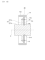
- Fig. 2 is a cross-sectional view taken along line II-II in Fig. 1.
- Fig. 3 is a cross-sectional view taken along line III-III in Fig. 1.
- a pair of bearings 12 are attached to the outer periphery of the shaft member 11.
- the cross-section of the shaft member 11 perpendicular to the axis C of the shaft member 11 has a circular shape.
- a hub 13 which is a rotatable inner rotating member, is attached to the outer periphery of the pair of bearings 12.
- the hub 13 is attached to the shaft member 11 via the pair of bearings 12.
- the hub 13 rotates relative to the shaft member 11 around the axis C.
- the hub 13 has a cylindrical mating portion 13a and a flange-shaped first fastening portion 13b.
- the mating portion 13a is positioned coaxially with the shaft member 11.
- a pair of bearings 12 are interposed between the outer peripheral surface of the shaft member 11 and the inner peripheral surface of the mating portion 13a.
- the first fastening portion 13b protrudes from the outer periphery of the mated portion 13a toward the outside in the radial direction of the mated portion 13a.
- the radial direction of the mated portion 13a is perpendicular to the axis C.
- the hub 13 in the first embodiment is constructed as a single component.
- An outer rotating member 14 is fixed to the hub 13.
- the outer rotating member 14 rotates together with the hub 13 around the axis C.
- the rotating body 10 in the first embodiment has the hub 13, the outer rotating member 14, and a plurality of fasteners 15.
- the outer rotating member 14 has an annular engaging portion 14a, a disk-shaped second fastening portion 14b, multiple connecting portions 14c, and a cylindrical outer periphery 14d.
- the engaging portion 14a is fitted and fixed to the outer periphery of the fitted portion 13a by shrink fitting.
- the second fastening portion 14b is provided radially outward of the fitting portion 14a.
- the radial direction of the fitting portion 14a is perpendicular to the axis C.
- the second fastening portion 14b also protrudes radially inward from the inner circumferential surface of the outer circumferential portion 14d.
- the second fastening portion 14b is overlapped with the first fastening portion 13b in the axial direction of the fitting portion 14a.
- the axial direction of the fitting portion 14a is parallel to the axis C, and corresponds to the left-right direction in FIG. 2.
- the second fastening portion 14b is fixed to the first fastening portion 13b by a plurality of fasteners 15.
- the plurality of fasteners 15 are arranged at equal intervals from one another in the circumferential direction of the fitting portion 14a.
- the circumferential direction of the fitting portion 14a is a direction along a circumference centered on the axis C.
- the plurality of fasteners 15 are also arranged on the same circumference centered on the axis C.
- each fastener 15 For example, a bolt is used as each fastener 15. Each bolt passes through the second fastening portion 14b parallel to the axis C and is screwed into a threaded hole in the first fastening portion 13b.
- the multiple connecting portions 14c are provided between the fitting portion 14a and the second fastening portion 14b at equal intervals in the circumferential direction of the fitting portion 14a.
- the multiple connecting portions 14c also connect the fitting portion 14a and the second fastening portion 14b.
- two connecting portions 14c are provided between the fitting portion 14a and the second fastening portion 14b.
- four fasteners 15 are used. Two of the four fasteners 15 are positioned in the same position as the connecting portions 14c in the circumferential direction of the fitting portion 14a.
- a plurality of gaps 14e are provided between the fitting portion 14a and the second fastening portion 14b, except for the plurality of connecting portions 14c.
- a pair of gaps 14e is provided between the fitting portion 14a and the second fastening portion 14b.
- each gap 14e when viewed along the axis C is an arc shape centered on the axis C.
- a connecting portion 14c is interposed between two adjacent gaps 14e in the circumferential direction of the fitting portion 14a.
- the multiple fasteners 15 are located outside the multiple connecting portions 14c and multiple gaps 14e in the radial direction of the fitting portion 14a.
- At least one of the inner peripheral surface of the mating portion 14a and the outer peripheral surface of the mated portion 13a has a recess.
- the inner peripheral surface of the mating portion 14a has a pair of notches 14f as recesses.
- the pair of notches 14f are located at the same positions as the pair of connecting portions 14c in the circumferential direction of the fitting portion 14a.
- Each notch 14f is provided continuously over the entire axial direction of the fitting portion 14a.
- the shape of each notch 14f when viewed along the axial direction of the fitting portion 14a is semicircular.
- the configuration of embodiment 1 makes it easy to fit the outer rotating member 14 into the fitting portion 13a.
- the hub 13 is also attached to the shaft member 11 via the bearing 12. This makes it easy to fit the outer rotating member 14 into the fitted portion 13a in a rotating body 10 that rotates relative to the shaft member 11.
- the engaging portion 14a When assembling the rotating body 10, the engaging portion 14a is engaged with the engaged portion 13a, and then the second fastening portion 14b is fixed to the first fastening portion 13b by a plurality of fasteners 15. After the engaging portion 14a is engaged with the engaged portion 13a, the temperature of the outer rotating member 14 drops, causing the outer rotating member 14 to shrink in all directions.
- the inner peripheral surface of the fitting portion 14a is provided with multiple recesses, i.e., multiple notches 14f, the force with which the fitting portion 14a tightens the fitted portion 13a is reduced. Therefore, when the outer rotating member 14 contracts, slippage occurs between the fitting portion 14a and the fitted portion 13a. This suppresses a decrease in the fastening force between the first fastening portion 13b and the second fastening portion 14b by the multiple fasteners 15. In other words, if each fastener 15 is a bolt, a decrease in the axial force of the bolt can be suppressed.
- FIG. 4 is a front view showing a rotating body 10 according to a first modified example of the first embodiment.
- FIG. 5 is a cross-sectional view taken along line V-V in FIG. 4.
- a pair of notches 13c are provided as recesses on the outer peripheral surface of the mated portion 13a.
- the contact area between the mating portion 14a and the mated portion 13a is reduced.
- the pair of notches 13c are located at the same position as the pair of connecting portions 14c in the circumferential direction of the fitting portion 14a.
- Each notch 13c is provided continuously over the entire fitted portion 13a in the axial direction of the fitting portion 14a.
- the shape of each notch 13c when viewed along the axial direction of the fitting portion 14a is semicircular.
- multiple notches 14f may be provided on the inner peripheral surface of the fitting portion 14a
- multiple notches 13c may be provided on the outer peripheral surface of the fitted portion 13a.
- FIG. 6 is a cross-sectional view showing a rotating body 10 according to a second modified example of the first embodiment. Note that FIG. 6 shows a cross section corresponding to the cross section along line II-II in FIG. 1.
- the hub 13 is formed by combining two members. That is, the first fastening portion 13b is formed as a separate member from the mated portion 13a. The first fastening portion 13b is then fixed to the outer periphery of the mated portion 13a by shrink fitting.
- the multiple fasteners 15 are positioned away from the mating portion 13a, which increases the diameter of the first fastening portion 13b and makes the hub 13 heavier. In contrast, by dividing the hub 13 into the mating portion 13a and the first fastening portion 13b, the hub 13 can be easily transported.
- FIG. 7 is a cross-sectional view showing a rotating body 10 according to a third modified example of the first embodiment. Note that FIG. 7 shows a cross-section corresponding to the cross-section along line V-V in FIG. 4.
- the first fastening portion 13b is configured as a separate member from the mated portion 13a.
- the first fastening portion 13b is fixed to the outer periphery of the mated portion 13a by shrink fitting.
- Fig. 8 is a front view showing a rotating body according to embodiment 2.
- Fig. 9 is a cross-sectional view taken along line IX-IX in Fig. 8.
- Fig. 10 is a cross-sectional view taken along line XX in Fig. 8.
- the rotating body 20 in embodiment 2 has a rotating shaft body 21 as an inner rotating member, an outer rotating member 14, and multiple fasteners 15.
- the rotating shaft body 21 has a shaft member 22 as a fitted portion and a flange member 23 as a first fastening portion.
- the flange member 23 is constructed as a separate member from the shaft member 22.
- the flange member 23 is fixed to the outer periphery of the shaft member 22 by shrink fitting. This allows the flange member 23 to rotate together with the shaft member 22.
- the fitting portion 14a is fitted and fixed to the outer periphery of the shaft member 22 by shrink fitting.
- the second fastening portion 14b is fixed to the flange member 23 by a plurality of fasteners 15. This allows the outer rotating member 14 to rotate together with the rotating shaft body 21 around the axis C of the rotating shaft body 21.
- the outer rotating member 14 can function mainly as a driven wheel, but in the second embodiment, the outer rotating member 14 can function mainly as a driving wheel.
- the other configurations in the second embodiment are the same as those in the first embodiment.
- a plurality of gaps 14e are provided between the fitting portion 14a and the second fastening portion 14b, except for a plurality of connecting portions 14c. Therefore, even when only the fitting portion 14a is heated, heat conduction to the second fastening portion 14b is suppressed, and the fitting portion 14a can be heated efficiently. This allows the hole in the fitting portion 14a to be expanded with a small amount of heat using a small heating device.
- the configuration of embodiment 2 makes it easy to fit the outer rotating member 14 to the shaft member 22.
- the outer rotating member 14 can also rotate together with the rotating shaft body 21. Therefore, in a rotating body 20 in which the rotating shaft body 21 rotates, the outer rotating member 14 can be easily fitted to the shaft member 22.
- the rotating shaft body 21 is divided into the shaft member 22 and the flange member 23, which makes it easier to transport the rotating shaft body 21.
- FIG. 11 is a front view showing a rotating body 20 according to a first modified example of the second embodiment.
- FIG. 12 is a cross-sectional view taken along line XII-XII in FIG. 11.
- a pair of notches 22a are provided as recesses on the outer peripheral surface of the shaft member 22.
- the pair of notches 22a are located at the same position as the pair of connecting portions 14c in the circumferential direction of the rotating shaft body 21.
- the circumferential direction of the rotating shaft body 21 is a direction along a circumference centered on the axis C.
- the shape of each notch 22a when viewed along the axial direction of the rotating shaft body 21 is semicircular.
- the axial direction of the rotating shaft body 21 is a direction parallel to the axis C, which is the left-right direction in FIG. 12.
- multiple notches 14f may be provided on the inner peripheral surface of the fitting portion 14a, and multiple notches 22a may be provided on the outer peripheral surface of the shaft member 22.
- FIG. 13 is a cross-sectional view showing a rotating body 20 according to a second modified example of the second embodiment. Note that FIG. 13 shows a cross section corresponding to the cross section along line IX-IX in FIG. 8.
- the rotating shaft body 21 has a cylindrical fitted portion 21a and a flange-shaped first fastening portion 21b.
- the first fastening portion 21b protrudes from the outer periphery of the fitted portion 21a toward the outside in the radial direction of the fitted portion 21a.
- the radial direction of the fitted portion 21a is perpendicular to the axis C.
- the rotating shaft body 21 in the second modified example of the second embodiment is constructed as a single component.
- the mating portion 14a is fitted and fixed to the outer periphery of the mated portion 21a by shrink fitting.
- the second fastening portion 14b is overlapped with the first fastening portion 21b in the axial direction of the mating portion 14a.
- the second fastening portion 14b is fixed to the first fastening portion 21b by multiple fasteners 15.
- FIG. 14 is a cross-sectional view showing a rotating body 20 according to a third modified example of the second embodiment. Note that FIG. 14 shows a cross section corresponding to the cross section along line XII-XII in FIG. 11.
- a pair of notches 21c are provided as recesses on the outer peripheral surface of the mated portion 21a, similar to the pair of notches 22a in the first modified example of the second embodiment.
- Fig. 15 is a front view showing a rotating body according to embodiment 3.
- Fig. 16 is a cross-sectional view taken along line XVI-XVI in Fig. 15.
- Fig. 17 is a cross-sectional view taken along line XVII-XVII in Fig. 15.
- Fig. 18 is an enlarged cross-sectional view showing part XVIII in Fig. 16.
- annular groove 14g is provided as a recess on the inner peripheral surface of the fitting portion 14a.
- the groove 14g is provided continuously around the entire circumference of the fitting portion 14a along the circumferential direction of the fitting portion 14a.
- the configuration of embodiment 3 makes it easy to fit the outer rotating member 14 into the fitting portion 13a.
- the hub 13 is also attached to the shaft member 11 via the bearing 12. This makes it easy to fit the outer rotating member 14 into the fitted portion 13a in a rotating body 30 that rotates relative to the shaft member 11.
- a groove 14g is provided on the inner peripheral surface of the fitting portion 14a. This prevents the multiple connecting portions 14c from interfering with the expansion of the hole of the fitting portion 14a when the fitting portion 14a is heated. This makes it even easier to fit the outer rotating member 14 into the fitted portion 13a.
- FIG. 19 is a front view showing a rotating body 30 according to a first modified example of the third embodiment.
- FIG. 20 is a cross-sectional view taken along line XX-XX in FIG. 19.
- a groove 14g may be provided on the inner peripheral surface of the fitting portion 14a, and a groove 13d may be provided on the outer peripheral surface of the fitted portion 13a.
- FIG. 21 is a front view showing a rotating body 30 according to a second modified example of embodiment 3.
- two arc-shaped grooves 13d are provided as recesses on the outer peripheral surface of the mating portion 13a. That is, in the second modified example of embodiment 3, the groove 13d in the first modified example of embodiment 3 is divided into two. The two grooves 13d are provided at equal intervals from each other in the circumferential direction of the mating portion 14a.
- the number of grooves 13d may be three or more.
- FIG. 22 is a front view showing a rotating body 30 according to a third modified example of the third embodiment.
- two arc-shaped grooves 14g are provided as recesses on the inner circumferential surface of the fitting portion 14a. That is, in the third modified example of the third embodiment, the groove 14g in the third embodiment is divided into two. The two grooves 14g are provided at equal intervals from each other in the circumferential direction of the fitting portion 14a.
- the number of grooves 14g may be three or more.
- FIG. 23 is a cross-sectional view showing a rotating body 30 according to a fourth modified example of the third embodiment. Note that FIG. 23 shows a cross section corresponding to the cross section along line XVI-XVI in FIG. 15.
- the hub 13 is formed by combining two members. That is, the first fastening portion 13b is formed as a separate member from the mated portion 13a. The first fastening portion 13b is fixed to the outer periphery of the mated portion 13a by shrink fitting.
- the hub 13 is divided into the mating portion 13a and the first fastening portion 13b, which makes it easier to transport the hub 13.
- the inner circumferential surface of the fitting portion 14a may have one annular groove 14g or two or more arc-shaped grooves 14g.
- FIG. 24 is a cross-sectional view showing a rotating body 30 according to a fifth modified example of the third embodiment. Note that FIG. 24 shows a cross-section corresponding to the cross-section along line XX-XX in FIG. 19.
- the hub 13 is formed by combining two members. That is, the first fastening portion 13b is formed as a separate member from the mated portion 13a. The first fastening portion 13b is then fixed to the outer periphery of the mated portion 13a by shrink fitting.
- the hub 13 is divided into the mating portion 13a and the first fastening portion 13b, which makes it easier to transport the hub 13.
- the outer peripheral surface of the mating portion 13a may have one annular groove 13d or two or more arc-shaped grooves 13d.
- notch 14f similar to embodiment 1 and notch 13c similar to the first variation of embodiment 1 may be provided.
- Fig. 25 is a front view showing a rotating body according to embodiment 4.
- Fig. 26 is a cross-sectional view taken along line XXVI-XXVI in Fig. 25.
- Fig. 27 is a cross-sectional view taken along line XXVII-XXVII in Fig. 25.
- annular groove 14g is provided as a recess on the inner peripheral surface of the fitting portion 14a.
- the groove 14g is provided continuously around the entire circumference of the fitting portion 14a along the circumferential direction of the fitting portion 14a.
- the configuration of embodiment 4 makes it easy to fit the outer rotating member 14 to the shaft member 22.
- the outer rotating member 14 can also rotate together with the rotating shaft body 21. Therefore, in a rotating body 40 in which the rotating shaft body 21 rotates, the outer rotating member 14 can be easily fitted to the shaft member 22.
- the rotating shaft body 21 is divided into the shaft member 22 and the flange member 23, which makes it easier to transport the rotating shaft body 21.
- a groove 14g is provided on the inner peripheral surface of the fitting portion 14a. This prevents the multiple connecting portions 14c from interfering with the expansion of the hole of the fitting portion 14a when the fitting portion 14a is heated. This makes it even easier to fit the outer rotating member 14 to the shaft member 22.
- a groove 14g is provided on the inner peripheral surface of the fitting portion 14a, so that the force with which the fitting portion 14a tightens the shaft member 22 is more reliably reduced. Therefore, if the outer rotating member 14 contracts after the fitting portion 14a is fitted into the fitted portion 13a, slippage occurs between the fitting portion 14a and the shaft member 22. This prevents a decrease in the fastening force between the first fastening portion 13b and the second fastening portion 14b by the multiple fasteners 15. In other words, if each fastener 15 is a bolt, a decrease in the axial force of the bolt can be prevented.
- FIG. 28 is a front view showing a rotating body 40 according to a first modified example of the fourth embodiment.
- FIG. 29 is a cross-sectional view taken along line XXIX-XXIX in FIG. 28.
- annular groove 22b is provided as a recess on the outer peripheral surface of the shaft member 22.
- the groove 22b is provided continuously around the entire circumference of the shaft member 22 along the circumferential direction of the fitting portion 14a.
- a groove 14g may be provided on the inner peripheral surface of the fitting portion 14a, and a groove 22b may be provided on the outer peripheral surface of the shaft member 22.
- FIG. 30 is a front view showing a rotating body 40 according to a second modified example of the fourth embodiment.
- two arc-shaped grooves 22b are provided as recesses on the outer peripheral surface of the shaft member 22. That is, in the second modified example of the fourth embodiment, the groove 22b in the first modified example of the fourth embodiment is divided into two. The two grooves 22b are provided at equal intervals from each other in the circumferential direction of the fitting portion 14a.
- the number of grooves 22b may be three or more.
- FIG. 31 is a front view showing a rotating body 40 according to a third modified example of the fourth embodiment.
- two arc-shaped grooves 14g are provided as recesses on the inner circumferential surface of the fitting portion 14a. That is, in the third modified example of the fourth embodiment, the groove 14g in the fourth embodiment is divided into two. The two grooves 14g are provided at equal intervals from each other in the circumferential direction of the fitting portion 14a.
- the number of grooves 14g may be three or more.
- FIG. 32 is a cross-sectional view showing a rotating body 40 according to a fourth modified example of the fourth embodiment. Note that FIG. 32 shows a cross-section corresponding to the cross-section along line XXVI-XXVI in FIG. 25.
- the rotating shaft body 21 has a cylindrical fitted portion 21a and a flange-shaped first fastening portion 21b.
- the first fastening portion 21b protrudes from the outer periphery of the mated portion 21a toward the radially outward side of the mated portion 21a.
- the rotating shaft body 21 in the fourth modified example of the fourth embodiment is constructed as a single part.
- the inner circumferential surface of the fitting portion 14a may have one annular groove 14g or two or more arc-shaped grooves 14g.
- FIG. 33 is a cross-sectional view showing a rotating body 40 according to a fifth modified example of the fourth embodiment. Note that FIG. 33 shows a cross-section corresponding to the cross-section along line XXIX-XXIX in FIG. 28.
- the rotating shaft body 21 has a cylindrical fitted portion 21a and a flange-shaped first fastening portion 21b.
- the first fastening portion 21b protrudes from the outer periphery of the fitted portion 21a toward the outside in the radial direction of the fitted portion 21a.
- the rotating shaft body 21 in the fifth modified example of the fourth embodiment is constructed as a single part.
- An annular groove 21d is provided as a recess on the outer periphery of the fitted portion 13a.
- two or more arc-shaped grooves 21d may be provided on the outer peripheral surface of the mating portion 21a.
- At least one of the notch 14f similar to the second embodiment and the notch 22a similar to the first variation of the second embodiment may be provided.
- the number of connecting portions 14c may be three or more.
- the number of fasteners 15 may be two, three, or five or more.
- FIG. 34 is a diagram showing an example of an elevator to which the rotating body 10, 20, 30, or 40 of this disclosure is applied.
- the elevator hoist 53 has a hoist motor 54, a hoist brake (not shown), and a drive sheave 55.
- the hoist motor 54 rotates the drive sheave 55.
- the hoist brake keeps the drive sheave 55 stationary.
- the hoist brake also brakes the rotation of the drive sheave 55.
- a suspension body 57 is wound around the drive sheave 55 and the deflector pulley 56.
- a plurality of ropes or belts are used as the suspension body 57.
- a cage 58 is connected to a first end of the suspension body 57.
- a counterweight 59 is connected to a second end of the suspension body 57.
- the car 58 and counterweight 59 are suspended in the hoistway 51 by a suspension 57.
- the car 58 and counterweight 59 move up and down in the hoistway 51 by rotating the drive sheave 55.
- a pair of car guide rails 60 and a pair of counterweight guide rails 61 are installed in the elevator 51.
- FIG. 34 only one car guide rail 60 and one counterweight guide rail 61 are shown.
- a pair of cage guide rails 60 guide the cage 58 as it ascends and descends.
- a pair of counterweight guide rails 61 guide the counterweight 59 as it ascends and descends.
- the car 58 has a car frame 62 and a car chamber 63.
- the suspension body 57 is connected to the car frame 62.
- the car chamber 63 is supported by the car frame 62.
- the rotating body 10, 20, 30 or 40 is used as the drive sheave 55.
- a suspension body 57 is wrapped around the outer peripheral surface of the outer peripheral portion 14d of the outer rotating member 14.
- the elevator type is not limited to the type shown in Figure 34, and may be, for example, a 2:1 roping type.
- the elevator may also be a machine room-less elevator, a double deck elevator, a one-shaft multi-car elevator, etc.
- the one-shaft multi-car elevator is a system in which an upper car and a lower car located directly below the upper car each independently ascend and descend in a common elevator shaft.
Landscapes
- Engineering & Computer Science (AREA)
- Civil Engineering (AREA)
- Mechanical Engineering (AREA)
- Structural Engineering (AREA)
- Rolls And Other Rotary Bodies (AREA)
- Shafts, Cranks, Connecting Bars, And Related Bearings (AREA)
Priority Applications (3)
| Application Number | Priority Date | Filing Date | Title |
|---|---|---|---|
| CN202380101789.7A CN121794210A (zh) | 2023-09-11 | 2023-09-11 | 旋转体以及电梯曳引机 |
| PCT/JP2023/032983 WO2025057261A1 (ja) | 2023-09-11 | 2023-09-11 | 回転体及びエレベーター巻上機 |
| JP2025545309A JPWO2025057261A1 (https=) | 2023-09-11 | 2023-09-11 |
Applications Claiming Priority (1)
| Application Number | Priority Date | Filing Date | Title |
|---|---|---|---|
| PCT/JP2023/032983 WO2025057261A1 (ja) | 2023-09-11 | 2023-09-11 | 回転体及びエレベーター巻上機 |
Publications (1)
| Publication Number | Publication Date |
|---|---|
| WO2025057261A1 true WO2025057261A1 (ja) | 2025-03-20 |
Family
ID=95021770
Family Applications (1)
| Application Number | Title | Priority Date | Filing Date |
|---|---|---|---|
| PCT/JP2023/032983 Pending WO2025057261A1 (ja) | 2023-09-11 | 2023-09-11 | 回転体及びエレベーター巻上機 |
Country Status (3)
| Country | Link |
|---|---|
| JP (1) | JPWO2025057261A1 (https=) |
| CN (1) | CN121794210A (https=) |
| WO (1) | WO2025057261A1 (https=) |
Citations (5)
| Publication number | Priority date | Publication date | Assignee | Title |
|---|---|---|---|---|
| WO2006064554A1 (ja) * | 2004-12-15 | 2006-06-22 | Mitsubishi Denki Kabushiki Kaisha | エレベータ用巻上機 |
| JP2009155070A (ja) * | 2007-12-27 | 2009-07-16 | Meidensha Corp | エレベータ用巻上機 |
| WO2016143110A1 (ja) * | 2015-03-12 | 2016-09-15 | 三菱電機株式会社 | 綱車 |
| CN107984962A (zh) * | 2017-12-26 | 2018-05-04 | 北京北摩高科摩擦材料股份有限公司 | 一种分体式的火车车轮 |
| WO2023119404A1 (ja) * | 2021-12-21 | 2023-06-29 | 三菱電機株式会社 | ロータ、モータ、圧縮機および冷凍サイクル装置 |
-
2023
- 2023-09-11 CN CN202380101789.7A patent/CN121794210A/zh active Pending
- 2023-09-11 WO PCT/JP2023/032983 patent/WO2025057261A1/ja active Pending
- 2023-09-11 JP JP2025545309A patent/JPWO2025057261A1/ja active Pending
Patent Citations (5)
| Publication number | Priority date | Publication date | Assignee | Title |
|---|---|---|---|---|
| WO2006064554A1 (ja) * | 2004-12-15 | 2006-06-22 | Mitsubishi Denki Kabushiki Kaisha | エレベータ用巻上機 |
| JP2009155070A (ja) * | 2007-12-27 | 2009-07-16 | Meidensha Corp | エレベータ用巻上機 |
| WO2016143110A1 (ja) * | 2015-03-12 | 2016-09-15 | 三菱電機株式会社 | 綱車 |
| CN107984962A (zh) * | 2017-12-26 | 2018-05-04 | 北京北摩高科摩擦材料股份有限公司 | 一种分体式的火车车轮 |
| WO2023119404A1 (ja) * | 2021-12-21 | 2023-06-29 | 三菱電機株式会社 | ロータ、モータ、圧縮機および冷凍サイクル装置 |
Also Published As
| Publication number | Publication date |
|---|---|
| CN121794210A (zh) | 2026-04-03 |
| JPWO2025057261A1 (https=) | 2025-03-20 |
Similar Documents
| Publication | Publication Date | Title |
|---|---|---|
| JP7188849B2 (ja) | 減速機およびアクチュエータ | |
| EP2551236B1 (en) | Manual chain block | |
| US20060151254A1 (en) | Elevator brake | |
| WO2025057261A1 (ja) | 回転体及びエレベーター巻上機 | |
| JP5657136B2 (ja) | エレベータ用巻上機、及びエレベータ用巻上機の製造方法 | |
| JP2014034435A (ja) | 補助ブレーキを備えるエレベータ | |
| EP3147529B1 (en) | Disc brake disc and method of making such disc | |
| JP4558724B2 (ja) | エレベータ用巻上機及びそのブレーキ装置 | |
| JP5951038B2 (ja) | エレベータの吊り車装置 | |
| WO2025057262A1 (ja) | 回転体及びエレベーター巻上機 | |
| JP7510121B1 (ja) | エレベータ用巻上機ユニット、巻上機及びエレベータ | |
| JP2020075794A (ja) | 巻上機及びエレベーター | |
| JP4499496B2 (ja) | エレベータ用巻上機 | |
| JP6332548B2 (ja) | 綱車 | |
| JP2023179915A (ja) | エレベータ巻上機及び追加綱車装置 | |
| JP2015037996A (ja) | 乗客コンベアのブレーキ装置 | |
| CN110891890B (zh) | 曳引工具驱动装置中的导向轮 | |
| JP7378656B1 (ja) | エレベータ巻上機 | |
| CA2472036A1 (en) | Elevator brake | |
| JP6949240B2 (ja) | 乗客コンベヤの非常制動装置 | |
| JP5590471B2 (ja) | 巻上機及びエレベータ | |
| JP5645326B1 (ja) | 乗客コンベアのブレーキ装置 | |
| WO2025141721A1 (ja) | 巻上機及びエレベーター | |
| KR100824493B1 (ko) | 엘리베이터용 권상기 | |
| JP2018177434A (ja) | エレベーター用巻上機 |
Legal Events
| Date | Code | Title | Description |
|---|---|---|---|
| 121 | Ep: the epo has been informed by wipo that ep was designated in this application |
Ref document number: 23952158 Country of ref document: EP Kind code of ref document: A1 |
|
| ENP | Entry into the national phase |
Ref document number: 2025545309 Country of ref document: JP Kind code of ref document: A |
|
| WWE | Wipo information: entry into national phase |
Ref document number: 2025545309 Country of ref document: JP |