EP2551236B1 - Manual chain block - Google Patents
Manual chain block Download PDFInfo
- Publication number
- EP2551236B1 EP2551236B1 EP20110759471 EP11759471A EP2551236B1 EP 2551236 B1 EP2551236 B1 EP 2551236B1 EP 20110759471 EP20110759471 EP 20110759471 EP 11759471 A EP11759471 A EP 11759471A EP 2551236 B1 EP2551236 B1 EP 2551236B1
- Authority
- EP
- European Patent Office
- Prior art keywords
- bearing
- auxiliary plate
- chain block
- hole
- drive shaft
- Prior art date
- Legal status (The legal status is an assumption and is not a legal conclusion. Google has not performed a legal analysis and makes no representation as to the accuracy of the status listed.)
- Active
Links
Images


Classifications
-
- B—PERFORMING OPERATIONS; TRANSPORTING
- B66—HOISTING; LIFTING; HAULING
- B66B—ELEVATORS; ESCALATORS OR MOVING WALKWAYS
- B66B1/00—Control systems of elevators in general
- B66B1/02—Control systems without regulation, i.e. without retroactive action
- B66B1/06—Control systems without regulation, i.e. without retroactive action electric
- B66B1/14—Control systems without regulation, i.e. without retroactive action electric with devices, e.g. push-buttons, for indirect control of movements
-
- B—PERFORMING OPERATIONS; TRANSPORTING
- B66—HOISTING; LIFTING; HAULING
- B66D—CAPSTANS; WINCHES; TACKLES, e.g. PULLEY BLOCKS; HOISTS
- B66D3/00—Portable or mobile lifting or hauling appliances
- B66D3/12—Chain or like hand-operated tackles with or without power transmission gearing between operating member and lifting rope, chain or cable
- B66D3/16—Chain or like hand-operated tackles with or without power transmission gearing between operating member and lifting rope, chain or cable operated by an endless chain passing over a pulley or a sprocket
Definitions
- the present invention relates to a manual chain block, and in particular to a manual chain block in which an arrangement of a reduction gear mechanism is redesigned to achieve further size reduction and weight reduction while ensuring adequate strength.
- a manual chain block used for a load lifting operation has been conventionally known, which includes a chain block main body, an upper hook for suspending the chain block main body, a load chain looped around a load sheave of the chain block main body, a lower hook connected to a lower end of the load chain, and a hand chain looped around a hand wheel.
- the hand chain includes, for example, an endless chain, an endless belt or an endless rope, and has a function of transmitting operational force of an operator to the hand wheel.
- the hand wheel is engaged with the endless chain, the endless belt or the endless rope to convert the operational force of the operator into rotational force.
- a manual chain block 1 has a pair of frames 2a and 2b opposed to each other with a predetermined spacing therebetween. Between these frames 2a and 2b, a base shaft 4 of a load sheave 3 is rotatably supported by bearings 4B. A drive shaft 5 is rotatably supported in a center hole 4a of the base shaft 4. A reduction gear mechanism 6 is interposed between the drive shaft 5 and the load sheave 3 such that rotational power of the drive shaft 5 is transmitted to the load sheave 3 at a decreased speed, in order to wind the load chain up and down.
- the reduction gear mechanism 6 includes a pinion gear 6a provided at one end of the drive shaft 5, two first reduction gears 6b and 6b which mesh with the pinion gear 6a, second reduction gears 6d and 6d provided on gear shafts 6c and 6c of the first reduction gears 6b and 6b, and a load gear 6e which meshes with the second reduction gears 6d and 6d.
- a bearing 6f is provided on the frame 2a at a position radially outside of the bearing 4B for supporting the base shaft 4 of the load sheave 3.
- the drive shaft 5 has a threaded portion 7 on the other end of the drive shaft 5 opposite to the pinion gear 6a.
- a mechanical brake 9 with a hand wheel 8 is screwed onto the threaded portion 7.
- the present invention is proposed to overcome the above-described problem, and has the object of providing a manual chain block that allows a reduction gear of a reduction gear mechanism to be positioned on an inner side of the apparatus, irrespective of an outer shape of a bearing of a load sheave, in order to achieve size reduction of the overall apparatus without impairing the strength of the apparatus.
- a manual chain block including a drive shaft capable of rotating in response to a manual operational force, and a load sheave around which a load chain is looped, the load sheave being mounted coaxially to the drive shaft, supported together with the drive shaft on a frame via a bearing and coupled to the drive shaft so that mechanical power is transmitted therebetween, via a reduction gear mechanism, wherein the reduction gear mechanism includes a pinion gear provided on the drive shaft, reduction gears which mesh with the pinion gear, and a load gear which is interlocked with the load sheave and meshes with the reduction gears, and wherein the manual chain block further includes an auxiliary plate mounted on a side surface of the frame and in the periphery of the bearing, the auxiliary plate including a stepped portion formed in a thrust direction of the bearing and having a bearing hole which serves as a bearing for the reduction gear.
- a conventional bearing for the reduction gears can be omitted. Therefore, even if the bearing for supporting the load sheave on the frame is a roller bearing having a large diameter, the shaft of the reduction gear can be positioned closer to the center despite the presence of such a bearing. This allows the reduction gear mechanism to occupy only a smaller space.
- the auxiliary plate can also bear force acting on the reduction gears and thrust force acting on the bearing for supporting the load sheave by means of the stepped portion of the auxiliary plate.
- the auxiliary plate has a draw portion formed by drawing so as to be spaced apart over a predetermined distance from a surface of the frame on which the auxiliary plate is mounted, a center hole formed in a center of the draw portion, and a bearing hole formed in the vicinity of the center hole and projecting toward the surface of the frame on which the auxiliary plate is mounted, so as to serve as a bearing for the reduction gear.
- the shaft of the reduction gear is supported by the bearing hole projecting toward the surface of the frame onto which the auxiliary plate is mounted.
- the bearing hole is formed in a tubular portion projecting toward the frame by means of burring.
- the manual chain block has a fixing hole for fixing the auxiliary plate by means of a rivet, the fixing hole being formed in the auxiliary plate in the vicinity of an outside of an outer edge of the draw portion.
- the auxiliary plate can be easily attached to the frame, while misalignment of the auxiliary plate is prevented.
- the tubular portion of the bearing hole of the auxiliary plate situated closer to the center hole is positioned so as to come in contact with a side surface of the bearing.
- the ordinary bearing for the gear shaft can be dispensed with in order to form a reduction gear mechanism.
- the gear shaft of the reduction gear mechanism can be positioned closer to the center. Accordingly, the overall size of the apparatus can be further reduced.
- the stepped portion can bear force in a thrust direction or the like, the auxiliary plate and the frame can be thinner.
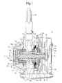
- Figs. 1 and 2 show a manual chain block 10 according to a first embodiment.
- the manual chain block 10 includes a first and a second main frames 11a and 11b disposed opposite to each other at a predetermined distance, and a load sheave 12 rotatably supported on the first and the second main frames 11a and 11b with bearings (ball bearings) 13a and 13b interposed therebetween.
- the load sheave 12 is supported by the bearings 13a and 13b at shaft portions 12a and 12b.
- a drive shaft 15 extends in a through-hole 12c extending through a central axis of the shaft portion 12a and 12b of the load sheave 12.
- the drive shaft 15 is supported so as to be rotatable relative to the load sheave 12 via needle bearings 14a and 14b.
- a reduction gear mechanism 16 is interposed between the drive shaft 15 and the load sheave 12, and rotational power output of the drive shaft 15 is transmitted to the load sheave 12 at a decreased speed.
- a gear cover Gc for housing the reduction gear mechanism 16 and a wheel cover Hc for housing a mechanical brake 19 and a hand wheel 20, which will be described below, are interconnected to each other and held by the first and the second main frames 11a and 11b by means of three stud bolts 17. Further, an upper hook 18 is pivotally attached to the first and the second main frames 11a and 11b by means of a shaft (not shown) fixed to an upper part of the first and the second main frames 11a and 11b.
- the reduction gear mechanism 16 is situated at the end of the left side of the drive shaft 15 which projects from the shaft portion 12a of the load sheave 12 toward the left side of the first main frame 11a.
- a thread (multiple thread) with relatively large lead extends to an axial end of the drive shaft 15 at the end of the right side of the drive shaft 15 which projects from the shaft portion 12b of the load sheave 12 toward the right side of the second frame 11b.
- the mechanical brake 19 provided with a hand wheel 20 is attached to the axial end of the drive shaft 15.
- the mechanical brake 19 includes a driven member 19a, a pair of brake members 19b and 19b interposed in the outer periphery of a boss portion of the driven member 19a, a ratchet gear 19d interposed between the brake members 19b and 19b via a bush 19c, a claw member 19f biased by a torsion spring 19e provided at the second main frame 11b so as to mesh with the ratchet gear 19d and prevent the ratchet gear 19d from rotating in a direction to wind down, and a drive member 19g integrally provided with a hand wheel 20 in the outer periphery thereof.
- An endless chain (not shown) is looped around the hand wheel 20 for transmitting operational force by an operator to the hand wheel 20.
- the drive member 19g is moved on the multiple thread of the drive shaft 15 so as to be pressed against the brake member 19b of the mechanical brake 19, and the hand wheel 20 and the drive shaft 15 are coupled together so that mechanical power is transmitted therebetween.
- rotational power of the hand wheel 20 when winding up is transmitted to the drive shaft 15.
- the drive member 19g releases the brake member 19b and the ratchet gear 19d which have been pressed against each other, terminating the braking action.
- the drive shaft 15 is able to rotate in the direction to wind down.
- the reduction gear mechanism 16 has a pinion gear 16a provided on the drive shaft 15, and a pair of first reduction gears 16b and 16b which mesh with the pinion gear 16a.
- the pinion gear 16a is a small gear having a toothed portion at the axial end of the drive shaft 15.
- the drive shaft 15 has a flange portion 15a adjacent to the pinion gear 16a and the flange portion 15a has a larger diameter as compared to the diameter of the shaft.
- a washer W is situated between the flange portion 15a and a portion projecting from the shaft portion 12a of the load sheave 12 to function as a stopper in a thrust direction.
- the pinion gear 16a meshes with the pair of the first reduction gears 16b and 16b, respectively, at a first stage of predetermined reduction ratio.
- the pair of the first reduction gears 16b and 16b are opposed to each other in a horizontal direction with the pinion gear 16a positioned at their center.
- the shaft portions of the pair of the first reduction gears 16b and 16b are supported by an end face of the gear cover Gc opposed to the axial end of the drive shaft 15 and by an auxiliary plate mounted onto the first main frame 11a, which will be described below.
- the reduction gear mechanism 16 has a pair of second reduction gears 16c and 16c provided on the shaft portions of the pair of the first reduction gears 16b, 16b, and a load gear 16d which meshes with the pair of the second reduction gears 16c and 16c at a second stage of predetermined reduction ratio.
- the load gear 16d is fitted onto the outer circumferential surface of the shaft portion 12a of the load sheave 12, and is held by means of a spline connection.
- the load gear 16d has a recess 16e in the center of the left end side thereof.
- the flange portion 15a is situated in the recess 16e and the end face of the load gear 16d on the left side is made flush with the flange portion 15a.
- a boss portion 16f is situated in the center of the load gear 16d on the opposite side of the recess 16e and bulges toward the bearing 13a.
- the boss portion 16f has a smaller diameter than the outer diameter of the load gear 16d.
- the boss portion 16f is inserted to a center hole 32 of an auxiliary plate 30, which will be described below, so as to extend in the center hole 32.
- the load gear 16d is positioned by a stepped portion of the shaft portion 12a.
- the auxiliary plate 30 is situated in the circumference of the bearing 13a of the first main frame 11a for supporting the shaft portion 12a of the load sheave 12.
- the auxiliary plate 30 is provided so as to be mounted on the side surface of the first main frame 11a.
- the auxiliary plate 30 is processed so as to be plastically deformed and form a stepped portion in a thrust direction.
- a draw portion 31 is formed by means of drawing, for example, such that its center portion is spaced apart from the end surface of the first main frame 11a over a predetermined distance. Then, the draw portion 31 is perforated, with the draw portion 31 as the center, to form a center hole 32 to which the bearing 13a can be fitted with the outer circumference of the bearing 13a in contact therewith.
- a stop ring 13r is provided on the bearings 13a and 13b in order to hold the bearings 13a and 13b against force applied by the load sheave 12 in a thrust direction.
- auxiliary plate 30 mounted to the first main frame 11a will be described in detail below.
- the first main frame 11a has an insertion hole 11ah through which the shaft portion 12a of the load sheave 12 is inserted via the bearing 13a.
- the auxiliary plate 30 is positioned by means of a shaft-like positioning jig fitted to the center hole 32 and the insertion hole 11ah such that a center of the center hole 32 of the auxiliary plate 30 coincides with that of the insertion hole 11ah.
- the auxiliary plate 30 is fixed to the first main frame 11a by means of rivets R.
- the center hole 32 needs not coincide with the insertion hole 11ah. Yet if the center hole 32 coincides with the insertion hole 11ah as shown in Figs. 1 and 2 , it is easy to position the center hole 32 and the insertion hole 11ah relative to each other, and the center hole 32 and the insertion hole 11ah can be spaced apart to support the outer circumference of the bearing 13a over a greater area. As a result, the bearing 13a can be firmly supported.
- the auxiliary plate 30 is provided with the draw portion 31 formed by means of drawing, for example, so as to separate a center portion of a steel plate material from the end surface of the first main frame 11a over a predetermined distance, as described above.
- the draw portion 31 has a bottom generally having a flat rhombus shape with rounded corners. Thereafter, the draw portion 31 is perforated at its center to form the center hole 32.
- Bearing holes 33 for the shaft portions 16br of the first reduction gears 16b are simultaneously formed by means of burring, for example, on both sides with the center hole 32 interposed therebetween.
- the bearing holes 33 are formed at equal distance from the center of the center hole 32 and on the longer diagonal line of the bottom rhombus of the draw portion 31.
- two or more fixing holes 34 are formed near the outer edge of the draw portion 31 in order to fix the auxiliary plate 30 to the first main frame 11a with the rivets R.
- the center of the auxiliary plate 30 is positioned relative to the first main frame 11a by means of the center hole 32 and the insertion hole 11ah.
- the auxiliary plate 30 has an embossed portion (half punched portion, not shown) in the vicinity of the fixing hole 34, and the embossed portion can be fitted to a positioning hole (not shown) of the first main frame 11a for positioning the center hole 32 in the circumferential direction. With the aid of the positioning hole and the embossed portion, the auxiliary plate 30 is positioned and fixed to the first main frame 11a with the rivets R. Tubular portions 33a of the bearing holes 33 of the auxiliary plate 30 are preferably held in close contact with the first main frame 11a.
- the auxiliary plate 30 as described above is subjected to predetermined heat treatment (hardening or the like) before fixed to the first main frame 11a.
- the auxiliary plate 30 serves as a bearing by being fixed to the first main frame 11a, while it also serves as an enforcing member for preventing the first main frame 11a from being deformed in the thrust direction by means of the draw portion 31.
- the axial end of the left end side of the first reduction gear 16b is supported by the bearing hole 35 formed, by means of burring, at a portion of the gear cover Gc opposed to the axial end of the drive shaft 15.
- a cover end plate Ct is attached to the outer side of the bearing hole 35, and certain grease is filled in the inner space of the gear cover Gc to ensure lubrication of each gear and bearing.
- the drive member 19g of the hand wheel 20 is moved on the multiple thread of the drive shaft 15 to come in contact with the brake member 19b of the mechanical brake 19 and tighten the brake member 19 and the like.
- the driven member 19a and the drive shaft 15 are coupled together so that mechanical power is transmitted therebetween, and rotational force of the hand wheel 20 is transmitted to the drive shaft 15.
- the drive member 19g of the hand wheel 20 is moved on the multiple thread of the drive shaft 15 away from the brake member 19b of the mechanical brake 19.
- the braking action of the mechanical brake 19 is terminated, and the drive shaft 15 is then able to rotate together with the hand wheel 20 in the direction to wind down.
- the load chain looped around the load sheave 12 is simultaneously wound down and a lower hook (not shown) for hanging a load can be lowered to the position of the load.
- the drive member 19g of the hand wheel 20 is moved on the multiple thread of the drive shaft 15 to come in contact with the brake member 19b of the mechanical brake 19 and tighten the brake member 19b and the like.
- the driven member 19a and the drive shaft 15 are coupled together so that mechanical power is transmitted therebetween, and rotational force of the hand wheel 20 is transmitted to the drive shaft 15.
- the load sheave 12 is rotated via the reduction gear mechanism 16 at a predetermined speed reduction ratio so as to wind the load up by the load chain.
- the pair of the first reduction gears 16b and 16b can be rotated with the bearing hole 35 of the gear cover Gc functioning as a bearing for the axial end on the left end side and with the bearing hole 33 near the center hole 32 of the auxiliary plate 30 functioning as a bearing on the right end side of the shaft portion 16br.
- the rotational force transmitted through the first stage of reduction ratio is transmitted to the load gear 16d at a second stage of reduction ratio through the second reduction gear 16c integrally formed on the shaft portion of the first reduction gears 16b and 16b.
- the rotational force is then transmitted to the load sheave 12 which is in a spline connection with the load gear 16d. In this way, the load gear 16d and the load sheave 12 are rotated together.
- the lateral surface of the toothed portion of the reduction gear 16c is opposed to the draw portion 31 of the auxiliary plate 30 mounted around the bearing 13a, so as to come into contact with the draw portion 31.
- force of the reduction gear 16c in a thrust direction and a radial direction produced when the reduction gear 16c is rotated together with the load sheave 12 is borne by the draw portion 31 of the auxiliary plate 30.
- the draw portion 31 of the auxiliary plate 30 is formed so as to be spaced apart from the end surface of the first main frame 11a over a predetermined distance. Further, the auxiliary plate 30 has been subjected to certain heat treatment. In addition, the tubular portion 33a of the bearing hole 33 of the auxiliary plate 30 is held in close contact with the first main frame 11a. In this way, the force of the reduction gear 16c in a thrust direction is borne by the first main frame 11a via the tubular portion 33a, and therefore, the auxiliary plate 30 can be reduced in wall thickness.
- the bearing holes 35 and 33 obtained by processing the gear cover Gc and the auxiliary plate can be used as bearings in place of ordinary bearings.
- the shaft of the reduction gear can be positioned as close to the center as possible.
- Such a configuration contributes to miniaturization of the manual chain block 10.
- the auxiliary plate 30 is held in close contact with the first main frame 11a via the tubular portion 33a of the bearing hole 33 with the center hole 32 of the draw portion 31 interposed therebetween, and therefore, the first main frame 11a and the auxiliary plate 30 form the composite structure.
- force is exerted on the load sheave 12 and the reduction gear in a distributed manner, so that the first main frame 11a and the auxiliary plate 30 can be made in reduced thickness.
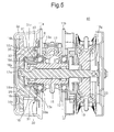
- Fig. 5 shows a manual chain block 40 according to a second embodiment.
- the manual chain block 40 according to the present embodiment basically has a configuration similar to that of the manual chain block 10 according to the first embodiment. Accordingly, substantially the same elements are denoted by the same reference numerals, and explanation thereon will be omitted.
- the auxiliary plate 30 is not situated around the outer periphery of the bearing 13a for supporting the shaft portion 12a of the load sheave 12, but extends between the toothed portion of the load gear 16d and the bearing 13a, and therefore closer to the shaft portion 12a of the load sheave 12.
- the axial end on the left end side of the first reduction gear 16b of the reduction gear mechanism 16 is rotatably supported in the bearing hole 35 formed in the gear cover Gc, while the right end side of the shaft portion 16br is rotatably supported in the bearing hole 33 of the auxiliary plate 30.
- the bearing hole 33 of the auxiliary plate 30 is close to the bearing 13a of the first main frame 11a in the radial direction, and the tubular portion 33a of the bearing hole 33 situated near the center is positioned so as to come in contact with the side surface of the bearing 13a.
- a bottom annular portion 31a of the draw portion 31 around the inner periphery of the center hole 32, rather than the tubular portion 33a, may also come in contact with the side surface of the bearing 13a.
- the shaft of the reduction gear be positioned closer to the center, but also the force in a thrust direction exerted onto the bearing 13a for supporting the shaft portion 12a of the load sheave 12 can be borne by the tubular portion 33a of the bearing hole 33 of the auxiliary plate 30 situated closer to the center, or by the annular portion 31a around the inner periphery of the center hole 32.
- the force exerted from the load sheave 12 onto the bearing 13a in a thrust direction can be borne by the portion of the auxiliary plate 30 extending between the toothed portion of the load gear 16d of the auxiliary plate 30 and the bearing 13a. Accordingly, the stop ring 13r provided on the bearing 13a for supporting force exerted from the load sheave 12 in a thrust direction can be dispensed with.
Description
- The present invention relates to a manual chain block, and in particular to a manual chain block in which an arrangement of a reduction gear mechanism is redesigned to achieve further size reduction and weight reduction while ensuring adequate strength.
- A manual chain block used for a load lifting operation has been conventionally known, which includes a chain block main body, an upper hook for suspending the chain block main body, a load chain looped around a load sheave of the chain block main body, a lower hook connected to a lower end of the load chain, and a hand chain looped around a hand wheel. The hand chain includes, for example, an endless chain, an endless belt or an endless rope, and has a function of transmitting operational force of an operator to the hand wheel. Similarly, the hand wheel is engaged with the endless chain, the endless belt or the endless rope to convert the operational force of the operator into rotational force.
- An exemplary configuration of a manual chin block as described above is disclosed in
JP 59-195193 U - As shown in
Fig. 6 , amanual chain block 1 has a pair offrames frames load sheave 3 is rotatably supported bybearings 4B. Adrive shaft 5 is rotatably supported in acenter hole 4a of the base shaft 4. Areduction gear mechanism 6 is interposed between thedrive shaft 5 and theload sheave 3 such that rotational power of thedrive shaft 5 is transmitted to theload sheave 3 at a decreased speed, in order to wind the load chain up and down. - The
reduction gear mechanism 6 includes apinion gear 6a provided at one end of thedrive shaft 5, twofirst reduction gears pinion gear 6a,second reduction gears gear shafts first reduction gears load gear 6e which meshes with thesecond reduction gears gear shafts first reduction gears bearing 6f is provided on theframe 2a at a position radially outside of thebearing 4B for supporting the base shaft 4 of theload sheave 3. - The
drive shaft 5 has a threadedportion 7 on the other end of thedrive shaft 5 opposite to thepinion gear 6a. Amechanical brake 9 with ahand wheel 8 is screwed onto the threadedportion 7. - Another exemplary configuration of a manual chain block is disclosed in
JP 58 161989 U - However, in the manual chain block as described above, the distances between axes of the
first reduction gears pinion gear 6a, and between axes of thesecond reduction gears load gear 6e are large, resulting in an increased diameter of each gear. In addition, because of thebearings 4B for supporting the base shaft 4 of theload sheave 3 and of thebearing 6f for supporting thegear shafts first reduction gears drive shaft 5. This prevents size reduction of themanual chain block 1. - The present invention is proposed to overcome the above-described problem, and has the object of providing a manual chain block that allows a reduction gear of a reduction gear mechanism to be positioned on an inner side of the apparatus, irrespective of an outer shape of a bearing of a load sheave, in order to achieve size reduction of the overall apparatus without impairing the strength of the apparatus.
- In order to achieve the above-described object, a manual chain block is provided as defined in
Claim 1, the manual chain block including a drive shaft capable of rotating in response to a manual operational force, and a load sheave around which a load chain is looped, the load sheave being mounted coaxially to the drive shaft, supported together with the drive shaft on a frame via a bearing and coupled to the drive shaft so that mechanical power is transmitted therebetween, via a reduction gear mechanism, wherein the reduction gear mechanism includes a pinion gear provided on the drive shaft, reduction gears which mesh with the pinion gear, and a load gear which is interlocked with the load sheave and meshes with the reduction gears, and wherein the manual chain block further includes an auxiliary plate mounted on a side surface of the frame and in the periphery of the bearing, the auxiliary plate including a stepped portion formed in a thrust direction of the bearing and having a bearing hole which serves as a bearing for the reduction gear. - With the above manual chain block, a conventional bearing for the reduction gears can be omitted. Therefore, even if the bearing for supporting the load sheave on the frame is a roller bearing having a large diameter, the shaft of the reduction gear can be positioned closer to the center despite the presence of such a bearing. This allows the reduction gear mechanism to occupy only a smaller space. The auxiliary plate can also bear force acting on the reduction gears and thrust force acting on the bearing for supporting the load sheave by means of the stepped portion of the auxiliary plate.
- In accordance with the invention as defined in Claim 2, the auxiliary plate has a draw portion formed by drawing so as to be spaced apart over a predetermined distance from a surface of the frame on which the auxiliary plate is mounted, a center hole formed in a center of the draw portion, and a bearing hole formed in the vicinity of the center hole and projecting toward the surface of the frame on which the auxiliary plate is mounted, so as to serve as a bearing for the reduction gear.
- With the above manual chain block, the shaft of the reduction gear is supported by the bearing hole projecting toward the surface of the frame onto which the auxiliary plate is mounted. This allows the auxiliary plate to be a thin plate made of steel, for example.
- In accordance with the invention as defined in
Claim 3, the bearing hole is formed in a tubular portion projecting toward the frame by means of burring. - With the above manual chain block, when the auxiliary plate is mounted onto the frame, the tubular portion defining the bearing hole abuts to the surface of the frame onto which the auxiliary plate is mounted, so that thrust force from the reduction gear acting on the bearing hole is transmitted to and is borne by the frame. Therefore, the thickness of the auxiliary plate can be reduced.
- In accordance with the invention as defined in Claim 4, the manual chain block has a fixing hole for fixing the auxiliary plate by means of a rivet, the fixing hole being formed in the auxiliary plate in the vicinity of an outside of an outer edge of the draw portion.
- With the above fixing hole, the auxiliary plate can be easily attached to the frame, while misalignment of the auxiliary plate is prevented.
- In accordance with the invention as defined in
Claim 5, the tubular portion of the bearing hole of the auxiliary plate situated closer to the center hole is positioned so as to come in contact with a side surface of the bearing. - With the above manual chain block, not only can the shaft of the reduction gear be positioned closer to the center, but force in a thrust direction acting on the bearing of the load sheave is borne by the tubular portion of the bearing hole of the auxiliary plate situated closer to the center. This eliminates a need for a thrust stop ring used for the bearing for supporting the load sheave.
- In accordance with the present invention, by means of an auxiliary plate having a stepped portion and defining a bearing hole which substitutes an ordinary bearing, which is usually used, the ordinary bearing for the gear shaft can be dispensed with in order to form a reduction gear mechanism. As a result, irrespective of the bearing for the load sheave, the gear shaft of the reduction gear mechanism can be positioned closer to the center. Accordingly, the overall size of the apparatus can be further reduced. In addition, since the stepped portion can bear force in a thrust direction or the like, the auxiliary plate and the frame can be thinner.
-
-
Fig. 1 is a longitudinal sectional view showing a manual chain block according to a first embodiment of the present invention; -
Fig. 2 is a transverse sectional view showing the manual chain block, taken along line A-A shown inFig. 1 ; -
Fig. 3 is a side view showing the manual chain block, seen from direction B shown inFig. 1 ; -
Fig. 4a is a plan view showing an arrangement of an assembly of a first main frame of the manual chain block shown inFig. 1 and of an auxiliary plate mounted onto the first main frame; -
Fig. 4b is a sectional view showing the first main frame and a holding plate, taken along line C-C shown inFig. 4a ; -
Fig. 5 is a longitudinal sectional view showing a manual chain block according to a second embodiment of the present invention; and -
Fig. 6 is a longitudinal sectional view showing an example of known manual chain block. - Various embodiments of a manual chain block according to the present invention will be described below with reference to appended drawings.
-
Figs. 1 and2 show amanual chain block 10 according to a first embodiment. - The
manual chain block 10 includes a first and a secondmain frames load sheave 12 rotatably supported on the first and the secondmain frames load sheave 12 is supported by thebearings shaft portions - In the
manual chain block 10, adrive shaft 15 extends in a through-hole 12c extending through a central axis of theshaft portion load sheave 12. Thedrive shaft 15 is supported so as to be rotatable relative to theload sheave 12 vianeedle bearings - A
reduction gear mechanism 16 is interposed between thedrive shaft 15 and theload sheave 12, and rotational power output of thedrive shaft 15 is transmitted to theload sheave 12 at a decreased speed. - A gear cover Gc for housing the
reduction gear mechanism 16 and a wheel cover Hc for housing amechanical brake 19 and ahand wheel 20, which will be described below, are interconnected to each other and held by the first and the secondmain frames stud bolts 17. Further, anupper hook 18 is pivotally attached to the first and the secondmain frames main frames - In the drawing, the
reduction gear mechanism 16 is situated at the end of the left side of thedrive shaft 15 which projects from theshaft portion 12a of theload sheave 12 toward the left side of the firstmain frame 11a. On the other hand, a thread (multiple thread) with relatively large lead extends to an axial end of thedrive shaft 15 at the end of the right side of thedrive shaft 15 which projects from theshaft portion 12b of theload sheave 12 toward the right side of thesecond frame 11b. Themechanical brake 19 provided with ahand wheel 20 is attached to the axial end of thedrive shaft 15. - The
mechanical brake 19 includes a drivenmember 19a, a pair ofbrake members member 19a, aratchet gear 19d interposed between thebrake members bush 19c, aclaw member 19f biased by a torsion spring 19e provided at the secondmain frame 11b so as to mesh with theratchet gear 19d and prevent theratchet gear 19d from rotating in a direction to wind down, and adrive member 19g integrally provided with ahand wheel 20 in the outer periphery thereof. - An endless chain (not shown) is looped around the
hand wheel 20 for transmitting operational force by an operator to thehand wheel 20. When thehand wheel 20 undergoes positive rotation by a hand chain, thedrive member 19g is moved on the multiple thread of thedrive shaft 15 so as to be pressed against thebrake member 19b of themechanical brake 19, and thehand wheel 20 and thedrive shaft 15 are coupled together so that mechanical power is transmitted therebetween. As a result, rotational power of thehand wheel 20 when winding up is transmitted to thedrive shaft 15. On the other hand, when thehand wheel 20 undergoes reverse rotation, thedrive member 19g releases thebrake member 19b and theratchet gear 19d which have been pressed against each other, terminating the braking action. As a result, thedrive shaft 15 is able to rotate in the direction to wind down. - Next, the
reduction gear mechanism 16 situated on the left end side of thedrive shaft 15 will be described. - Referring also to
Fig. 3 , thereduction gear mechanism 16 has apinion gear 16a provided on thedrive shaft 15, and a pair of first reduction gears 16b and 16b which mesh with thepinion gear 16a. - The
pinion gear 16a is a small gear having a toothed portion at the axial end of thedrive shaft 15. Thedrive shaft 15 has aflange portion 15a adjacent to thepinion gear 16a and theflange portion 15a has a larger diameter as compared to the diameter of the shaft. A washer W is situated between theflange portion 15a and a portion projecting from theshaft portion 12a of theload sheave 12 to function as a stopper in a thrust direction. - The
pinion gear 16a meshes with the pair of the first reduction gears 16b and 16b, respectively, at a first stage of predetermined reduction ratio. The pair of the first reduction gears 16b and 16b are opposed to each other in a horizontal direction with thepinion gear 16a positioned at their center. In this case, as will be described below, the shaft portions of the pair of the first reduction gears 16b and 16b are supported by an end face of the gear cover Gc opposed to the axial end of thedrive shaft 15 and by an auxiliary plate mounted onto the firstmain frame 11a, which will be described below. - Referring to
Fig. 2 , thereduction gear mechanism 16 has a pair of second reduction gears 16c and 16c provided on the shaft portions of the pair of the first reduction gears 16b, 16b, and aload gear 16d which meshes with the pair of the second reduction gears 16c and 16c at a second stage of predetermined reduction ratio. - The
load gear 16d is fitted onto the outer circumferential surface of theshaft portion 12a of theload sheave 12, and is held by means of a spline connection. Theload gear 16d has arecess 16e in the center of the left end side thereof. Theflange portion 15a is situated in therecess 16e and the end face of theload gear 16d on the left side is made flush with theflange portion 15a. Aboss portion 16f is situated in the center of theload gear 16d on the opposite side of therecess 16e and bulges toward thebearing 13a. Theboss portion 16f has a smaller diameter than the outer diameter of theload gear 16d. Theboss portion 16f is inserted to acenter hole 32 of anauxiliary plate 30, which will be described below, so as to extend in thecenter hole 32. Theload gear 16d is positioned by a stepped portion of theshaft portion 12a. - The
auxiliary plate 30 is situated in the circumference of thebearing 13a of the firstmain frame 11a for supporting theshaft portion 12a of theload sheave 12. Theauxiliary plate 30 is provided so as to be mounted on the side surface of the firstmain frame 11a. Theauxiliary plate 30 is processed so as to be plastically deformed and form a stepped portion in a thrust direction. - In order to prepare the
auxiliary plate 30, adraw portion 31 is formed by means of drawing, for example, such that its center portion is spaced apart from the end surface of the firstmain frame 11a over a predetermined distance. Then, thedraw portion 31 is perforated, with thedraw portion 31 as the center, to form acenter hole 32 to which thebearing 13a can be fitted with the outer circumference of thebearing 13a in contact therewith. - The
bearings load sheave 12 via theshaft portions load sheave 12 which projects in the form of a flange inside the opposing first and secondmain frames stop ring 13r is provided on thebearings bearings load sheave 12 in a thrust direction. - With also reference to
Figs. 4a and 4b , theauxiliary plate 30 mounted to the firstmain frame 11a will be described in detail below. - The first
main frame 11a has an insertion hole 11ah through which theshaft portion 12a of theload sheave 12 is inserted via thebearing 13a. Theauxiliary plate 30 is positioned by means of a shaft-like positioning jig fitted to thecenter hole 32 and the insertion hole 11ah such that a center of thecenter hole 32 of theauxiliary plate 30 coincides with that of the insertion hole 11ah. Theauxiliary plate 30 is fixed to the firstmain frame 11a by means of rivets R. - Therefore, if the positioning jig has such a shaft diameter portion fitted to the
center hole 32 and the insertion hole 11ah, thecenter hole 32 needs not coincide with the insertion hole 11ah. Yet if thecenter hole 32 coincides with the insertion hole 11ah as shown inFigs. 1 and2 , it is easy to position thecenter hole 32 and the insertion hole 11ah relative to each other, and thecenter hole 32 and the insertion hole 11ah can be spaced apart to support the outer circumference of thebearing 13a over a greater area. As a result, thebearing 13a can be firmly supported. - Accordingly, the
auxiliary plate 30 is provided with thedraw portion 31 formed by means of drawing, for example, so as to separate a center portion of a steel plate material from the end surface of the firstmain frame 11a over a predetermined distance, as described above. Thedraw portion 31 has a bottom generally having a flat rhombus shape with rounded corners. Thereafter, thedraw portion 31 is perforated at its center to form thecenter hole 32. Bearing holes 33 for the shaft portions 16br of the first reduction gears 16b are simultaneously formed by means of burring, for example, on both sides with thecenter hole 32 interposed therebetween. The bearing holes 33 are formed at equal distance from the center of thecenter hole 32 and on the longer diagonal line of the bottom rhombus of thedraw portion 31. Further, two or more fixing holes 34 are formed near the outer edge of thedraw portion 31 in order to fix theauxiliary plate 30 to the firstmain frame 11a with the rivets R. - The center of the
auxiliary plate 30 is positioned relative to the firstmain frame 11a by means of thecenter hole 32 and the insertion hole 11ah. Theauxiliary plate 30 has an embossed portion (half punched portion, not shown) in the vicinity of the fixinghole 34, and the embossed portion can be fitted to a positioning hole (not shown) of the firstmain frame 11a for positioning thecenter hole 32 in the circumferential direction. With the aid of the positioning hole and the embossed portion, theauxiliary plate 30 is positioned and fixed to the firstmain frame 11a with the rivetsR. Tubular portions 33a of the bearing holes 33 of theauxiliary plate 30 are preferably held in close contact with the firstmain frame 11a. - The
auxiliary plate 30 as described above is subjected to predetermined heat treatment (hardening or the like) before fixed to the firstmain frame 11a. Theauxiliary plate 30 serves as a bearing by being fixed to the firstmain frame 11a, while it also serves as an enforcing member for preventing the firstmain frame 11a from being deformed in the thrust direction by means of thedraw portion 31. - The axial end of the left end side of the
first reduction gear 16b is supported by the bearinghole 35 formed, by means of burring, at a portion of the gear cover Gc opposed to the axial end of thedrive shaft 15. A cover end plate Ct is attached to the outer side of the bearinghole 35, and certain grease is filled in the inner space of the gear cover Gc to ensure lubrication of each gear and bearing. - The configuration of the
manual chain block 10 according to the first embodiment has been described above. An operation and function of themanual chain block 10 will be now described. - When the
hand wheel 20 undergoes positive rotation as the hand chain (not shown) is operated, thedrive member 19g of thehand wheel 20 is moved on the multiple thread of thedrive shaft 15 to come in contact with thebrake member 19b of themechanical brake 19 and tighten thebrake member 19 and the like. As a result, the drivenmember 19a and thedrive shaft 15 are coupled together so that mechanical power is transmitted therebetween, and rotational force of thehand wheel 20 is transmitted to thedrive shaft 15. - On the other hand, when the
hand wheel 20 undergoes rotation in a direction opposite to the above-described rotation, thedrive member 19g of thehand wheel 20 is moved on the multiple thread of thedrive shaft 15 away from thebrake member 19b of themechanical brake 19. As a result, the braking action of themechanical brake 19 is terminated, and thedrive shaft 15 is then able to rotate together with thehand wheel 20 in the direction to wind down. The load chain looped around theload sheave 12 is simultaneously wound down and a lower hook (not shown) for hanging a load can be lowered to the position of the load. - When the load is hooked to the lower hook and the
hand wheel 20 undergoes positive rotation, thedrive member 19g of thehand wheel 20 is moved on the multiple thread of thedrive shaft 15 to come in contact with thebrake member 19b of themechanical brake 19 and tighten thebrake member 19b and the like. As a result, the drivenmember 19a and thedrive shaft 15 are coupled together so that mechanical power is transmitted therebetween, and rotational force of thehand wheel 20 is transmitted to thedrive shaft 15. Accordingly, theload sheave 12 is rotated via thereduction gear mechanism 16 at a predetermined speed reduction ratio so as to wind the load up by the load chain. - When rotational force of the
hand wheel 20 is transmitted to thedrive shaft 15, the rotational force is transmitted at a predetermined first speed reduction ratio from thepinion gear 16a at the axial end of thedrive shaft 15 to the pair of the first reduction gears 16b and 16b opposed to each other in a horizontal direction with thepinion gear 16a situated as a center thereof. - The pair of the first reduction gears 16b and 16b can be rotated with the bearing
hole 35 of the gear cover Gc functioning as a bearing for the axial end on the left end side and with the bearinghole 33 near thecenter hole 32 of theauxiliary plate 30 functioning as a bearing on the right end side of the shaft portion 16br. - The rotational force transmitted through the first stage of reduction ratio is transmitted to the
load gear 16d at a second stage of reduction ratio through thesecond reduction gear 16c integrally formed on the shaft portion of the first reduction gears 16b and 16b. The rotational force is then transmitted to theload sheave 12 which is in a spline connection with theload gear 16d. In this way, theload gear 16d and theload sheave 12 are rotated together. - As described above, the lateral surface of the toothed portion of the
reduction gear 16c is opposed to thedraw portion 31 of theauxiliary plate 30 mounted around thebearing 13a, so as to come into contact with thedraw portion 31. As a result, force of thereduction gear 16c in a thrust direction and a radial direction produced when thereduction gear 16c is rotated together with theload sheave 12 is borne by thedraw portion 31 of theauxiliary plate 30. - The
draw portion 31 of theauxiliary plate 30 is formed so as to be spaced apart from the end surface of the firstmain frame 11a over a predetermined distance. Further, theauxiliary plate 30 has been subjected to certain heat treatment. In addition, thetubular portion 33a of the bearinghole 33 of theauxiliary plate 30 is held in close contact with the firstmain frame 11a. In this way, the force of thereduction gear 16c in a thrust direction is borne by the firstmain frame 11a via thetubular portion 33a, and therefore, theauxiliary plate 30 can be reduced in wall thickness. - As described above, in the
manual chain block 10, in order to provide the pair of the first reduction gears 16b and 16b that may give rise to a problem relating to a space in thereduction gear mechanism 16, the bearing holes 35 and 33 obtained by processing the gear cover Gc and the auxiliary plate can be used as bearings in place of ordinary bearings. - Specifically, since the bearing
hole 33 of theauxiliary plate 30 is formed in the proximity of thecenter hole 32 and adjacent to thebearing 13a for supporting theshaft portion 12a of theload sheave 12, the shaft of the reduction gear can be positioned as close to the center as possible. Such a configuration contributes to miniaturization of themanual chain block 10. - In addition, the
auxiliary plate 30 is held in close contact with the firstmain frame 11a via thetubular portion 33a of the bearinghole 33 with thecenter hole 32 of thedraw portion 31 interposed therebetween, and therefore, the firstmain frame 11a and theauxiliary plate 30 form the composite structure. As a result, force is exerted on theload sheave 12 and the reduction gear in a distributed manner, so that the firstmain frame 11a and theauxiliary plate 30 can be made in reduced thickness. -
Fig. 5 shows amanual chain block 40 according to a second embodiment. Themanual chain block 40 according to the present embodiment basically has a configuration similar to that of themanual chain block 10 according to the first embodiment. Accordingly, substantially the same elements are denoted by the same reference numerals, and explanation thereon will be omitted. - In this
manual chain block 40, in order to allow the shaft of the reduction gears to be located close to the center, or in order to allow a bearing (ball bearing) 13a having a large diameter to be used, theauxiliary plate 30 is not situated around the outer periphery of thebearing 13a for supporting theshaft portion 12a of theload sheave 12, but extends between the toothed portion of theload gear 16d and thebearing 13a, and therefore closer to theshaft portion 12a of theload sheave 12. - In the
manual chain block 40, too, the axial end on the left end side of thefirst reduction gear 16b of thereduction gear mechanism 16 is rotatably supported in thebearing hole 35 formed in the gear cover Gc, while the right end side of the shaft portion 16br is rotatably supported in thebearing hole 33 of theauxiliary plate 30. - In this case, the bearing
hole 33 of theauxiliary plate 30 is close to thebearing 13a of the firstmain frame 11a in the radial direction, and thetubular portion 33a of the bearinghole 33 situated near the center is positioned so as to come in contact with the side surface of thebearing 13a. - With the above configuration and arrangement, force in a thrust direction exerted onto the
bearing 13a for supporting theshaft portion 12a of theload sheave 12 can be borne by thetubular portion 33a of the bearinghole 33 of theauxiliary plate 30 situated closer to the center. - If the outer diameter of the
bearing 13a is smaller relative to the position where thetubular portion 33a is provided, a bottomannular portion 31a of thedraw portion 31 around the inner periphery of thecenter hole 32, rather than thetubular portion 33a, may also come in contact with the side surface of thebearing 13a. - In accordance with the
manual chain block 40 as described above, not only can the shaft of the reduction gear be positioned closer to the center, but also the force in a thrust direction exerted onto thebearing 13a for supporting theshaft portion 12a of theload sheave 12 can be borne by thetubular portion 33a of the bearinghole 33 of theauxiliary plate 30 situated closer to the center, or by theannular portion 31a around the inner periphery of thecenter hole 32. - Also, the force exerted from the
load sheave 12 onto thebearing 13a in a thrust direction can be borne by the portion of theauxiliary plate 30 extending between the toothed portion of theload gear 16d of theauxiliary plate 30 and thebearing 13a. Accordingly, thestop ring 13r provided on thebearing 13a for supporting force exerted from theload sheave 12 in a thrust direction can be dispensed with. - Although the present invention has been described above with reference to particular embodiments, it will be apparent to those skilled in the art that various modifications or alterations can be made without departing from the scope as defined by the appended claims.
-
- 10
- manual chain block
- 11a
- first main frame
- 11ah
- insertion hole
- 11b
- second main frame
- 12
- load sheave
- 12a, 12b
- shaft portion
- 12c
- through hole
- 13a, 13b
- bearing
- 13r
- stop ring
- 14a, 14b
- needle bearing
- 15
- drive shaft
- 15a
- flange portion
- 16
- reduction gear mechanism
- 16a
- pinion gear
- 16b
- first reduction gear
- 16br
- shaft portion
- 16c
- second reduction gear
- 16d
- load gear
- 16f
- boss portion
- 17
- stud bolt
- 18
- upper hook
- 19
- mechanical brake
- 19a
- driven member
- 19b
- brake member
- 19c
- bush
- 19d
- ratchet gear
- 19e
- torsion spring
- 19f
- claw member
- 20
- hand wheel
- 30
- auxiliary plate
- 31
- draw portion
- 31a
- bottom annular portion
- 32
- center hole
- 33
- bearing hole
- 33a
- tubular portion
- 34
- fixing hole
- 35
- bearing hole
- 40
- manual chain block
- Gc
- gear cover
- Hc
- wheel cover
- W
- washer
- R
- rivet
- Ct
- cover end plate
Claims (5)
- A manual chain block (10, 40) comprising:a drive shaft (15) capable of rotating in response to a manual operational force; anda load sheave (12) around which a load chain is looped, the load sheave (12) being mounted coaxially to the drive shaft (15), supported together with the drive shaft (15) on a frame (11 a) via a bearing (13a) and coupled to the drive shaft (15) so that mechanical power is transmitted therebetween, via a reduction gear mechanism (16), whereinthe reduction gear mechanism (16) includes a pinion gear (16a) provided on the drive shaft (15), reduction gears (16b, 16c) which mesh with the pinion gear (16a), and a load gear (16d) which is interlocked with the load sheave (12) and meshes with the reduction gears (16b, 16c), characterized in thatthe manual chain block (10, 40) further comprises an auxiliary plate (30) mounted on a side surface of the frame (11a) and in the periphery of the bearing (13a), the auxiliary plate (30) including a stepped portion formed in a thrust direction of the bearing (13a) and having a bearing hole (33) which serves as a bearing for the reduction gear (16b).
- The manual chain block (10, 40) according to claim 1, characterized in that the auxiliary plate (30) includes:a draw portion (31) formed by drawing so as to be spaced apart over a predetermined distance from a surface of the frame (11a) on which the auxiliary plate (30) is mounted,a center hole (32) formed in a center of the draw portion (31), anda bearing hole (33) formed in the vicinity of the center hole (32) and projecting toward the surface of the frame (11 a) on which the auxiliary plate (30) is mounted, so as to serve as a bearing for the reduction gear (16b).
- The manual chain block (10, 40) according to claim 2, characterized in that the bearing hole (33) is formed in a tubular portion (33a) projecting toward the frame (11a) by means of burring.
- The manual chain block (10, 40) according to claim 3, characterized by further comprising a fixing hole (34) for fixing the auxiliary plate (30) by means of a rivet (R), the fixing hole (34) being formed in the auxiliary plate (30) in the vicinity of an outside of an outer edge of the draw portion (31).
- The manual chain block (40) according to claim 3, characterized in that the tubular portion (33a) of the bearing hole (33) of the auxiliary plate (30) situated closer to the center hole (32) is positioned so as to come in contact with a side surface of the bearing (13a).
Applications Claiming Priority (2)
| Application Number | Priority Date | Filing Date | Title |
|---|---|---|---|
| JP2010069912A JP5550410B2 (en) | 2010-03-25 | 2010-03-25 | Manual chain block |
| PCT/JP2011/057060 WO2011118666A1 (en) | 2010-03-25 | 2011-03-16 | Manual chain block |
Publications (3)
| Publication Number | Publication Date |
|---|---|
| EP2551236A1 EP2551236A1 (en) | 2013-01-30 |
| EP2551236A4 EP2551236A4 (en) | 2013-10-09 |
| EP2551236B1 true EP2551236B1 (en) | 2015-05-13 |
Family
ID=44673215
Family Applications (1)
| Application Number | Title | Priority Date | Filing Date |
|---|---|---|---|
| EP20110759471 Active EP2551236B1 (en) | 2010-03-25 | 2011-03-16 | Manual chain block |
Country Status (9)
| Country | Link |
|---|---|
| US (1) | US9284172B2 (en) |
| EP (1) | EP2551236B1 (en) |
| JP (1) | JP5550410B2 (en) |
| KR (1) | KR101456348B1 (en) |
| CN (1) | CN102834344B (en) |
| AU (1) | AU2011230372B2 (en) |
| BR (1) | BR112012024043B1 (en) |
| CA (1) | CA2793962C (en) |
| WO (1) | WO2011118666A1 (en) |
Families Citing this family (8)
| Publication number | Priority date | Publication date | Assignee | Title |
|---|---|---|---|---|
| JP5827188B2 (en) | 2012-07-30 | 2015-12-02 | 株式会社キトー | Chain block |
| JP6068857B2 (en) * | 2012-07-30 | 2017-01-25 | 株式会社キトー | Chain block |
| JP6029955B2 (en) * | 2012-11-30 | 2016-11-24 | 株式会社キトー | Chain block |
| JP2014108839A (en) | 2012-11-30 | 2014-06-12 | Kito Corp | Chain block and load chain |
| US10093084B2 (en) | 2014-02-26 | 2018-10-09 | Jowat Se | Laminating process employing grid-like adhesive application |
| CN106976812B (en) * | 2017-04-11 | 2022-08-09 | 陈树忠 | No-load and on-load lifting speed changing mechanism of chain block |
| CN106882718B (en) * | 2017-04-17 | 2018-09-25 | 维多利科技(江苏)有限公司 | A kind of improved Lever Blocks structure |
| US10099904B1 (en) * | 2017-05-25 | 2018-10-16 | James Zaguroli, Jr. | Safety arrangement for a hoist |
Family Cites Families (13)
| Publication number | Priority date | Publication date | Assignee | Title |
|---|---|---|---|---|
| JPS5227808Y2 (en) * | 1973-05-14 | 1977-06-24 | ||
| JPS5759223A (en) | 1980-09-26 | 1982-04-09 | Toshiba Corp | Keyboard device |
| JPH0243789B2 (en) | 1981-11-24 | 1990-10-01 | Toshiba Electric Equip | KEIKOMAKUNOKEISEIHOHO |
| PT76165A (en) | 1982-02-02 | 1983-02-01 | Plast Labor Sa | Marking agent used namely for the marking of explosives and method for its manufacture |
| JPS58161989U (en) * | 1982-04-21 | 1983-10-28 | 三菱電機株式会社 | electric hoist |
| JPS59195193A (en) | 1983-04-21 | 1984-11-06 | 富士電機株式会社 | Fuel storage tank away from reactor |
| JPS59195193U (en) * | 1983-06-10 | 1984-12-25 | 象印チエンブロツク株式会社 | winding machine |
| CN2067699U (en) * | 1990-03-18 | 1990-12-19 | 夏元峰 | Automatic variable speed hand pulling hoist |
| US5556078A (en) * | 1992-12-16 | 1996-09-17 | Elephant Chain Block Company Limited | Manual hoist and traction machine |
| AU666078B2 (en) * | 1993-07-02 | 1996-01-25 | Elephant Chain Block Company Limited | Manual chain block |
| JP3355484B2 (en) * | 1998-11-19 | 2002-12-09 | 象印チエンブロック株式会社 | Hoisting machine |
| JP3416608B2 (en) | 2000-03-27 | 2003-06-16 | 株式会社キトー | Hoisting and traction devices |
| JP4101036B2 (en) * | 2002-11-18 | 2008-06-11 | 株式会社キトー | Hoisting and towing device |
-
2010
- 2010-03-25 JP JP2010069912A patent/JP5550410B2/en active Active
-
2011
- 2011-03-16 KR KR1020127024320A patent/KR101456348B1/en active IP Right Grant
- 2011-03-16 EP EP20110759471 patent/EP2551236B1/en active Active
- 2011-03-16 WO PCT/JP2011/057060 patent/WO2011118666A1/en active Application Filing
- 2011-03-16 BR BR112012024043-9A patent/BR112012024043B1/en active IP Right Grant
- 2011-03-16 US US13/634,845 patent/US9284172B2/en active Active
- 2011-03-16 AU AU2011230372A patent/AU2011230372B2/en active Active
- 2011-03-16 CN CN201180015310.5A patent/CN102834344B/en active Active
- 2011-03-16 CA CA2793962A patent/CA2793962C/en active Active
Also Published As
| Publication number | Publication date |
|---|---|
| EP2551236A4 (en) | 2013-10-09 |
| KR20120127505A (en) | 2012-11-21 |
| BR112012024043B1 (en) | 2021-05-18 |
| AU2011230372A1 (en) | 2012-10-04 |
| US9284172B2 (en) | 2016-03-15 |
| CN102834344B (en) | 2015-03-04 |
| WO2011118666A1 (en) | 2011-09-29 |
| CN102834344A (en) | 2012-12-19 |
| CA2793962A1 (en) | 2011-09-29 |
| CA2793962C (en) | 2015-07-14 |
| BR112012024043A2 (en) | 2016-08-30 |
| EP2551236A1 (en) | 2013-01-30 |
| AU2011230372B2 (en) | 2015-01-22 |
| KR101456348B1 (en) | 2014-11-03 |
| JP2011201637A (en) | 2011-10-13 |
| JP5550410B2 (en) | 2014-07-16 |
| US20130001489A1 (en) | 2013-01-03 |
Similar Documents
| Publication | Publication Date | Title |
|---|---|---|
| EP2551236B1 (en) | Manual chain block | |
| JP7188849B2 (en) | Reducer and Actuator | |
| JP4965109B2 (en) | Pulley | |
| JP2012046150A (en) | Vehicle hub unit | |
| EP2233789A1 (en) | Ball screw device | |
| JPWO2014129658A1 (en) | Power transmission device | |
| US20140260743A1 (en) | Wheel driving apparatus | |
| JP5170553B2 (en) | Drive plate for power transmission | |
| JP2014122689A (en) | Reduction gear | |
| JP5867121B2 (en) | Wheel support device | |
| RU2719091C1 (en) | Roller-screw reduction gear (embodiments), drive mechanism and hinged assembly comprising such reduction gear | |
| KR20100083230A (en) | Axle device for vehicle | |
| JPH09317847A (en) | Drive plate for vehicle | |
| JP6373593B2 (en) | Bearing retainer mounting structure for transmission | |
| JP6863095B2 (en) | Electric motor | |
| JP4513635B2 (en) | Ring gear flange | |
| KR20120058935A (en) | axle assembly for a driving wheel of vehicle | |
| JP4817686B2 (en) | Drive shaft speed reducer | |
| CN202597668U (en) | planet carrier and a cylindrical flange used by the planet carrier | |
| JP2002227875A (en) | Torque limiter | |
| JPH0442316Y2 (en) | ||
| JP2011231836A (en) | Bearing device | |
| JP2009085243A (en) | Rotor support structure | |
| JPH0699115B2 (en) | Lever type hoist | |
| JP2011220361A (en) | Differential case structure |
Legal Events
| Date | Code | Title | Description |
|---|---|---|---|
| PUAI | Public reference made under article 153(3) epc to a published international application that has entered the european phase |
Free format text: ORIGINAL CODE: 0009012 |
|
| 17P | Request for examination filed |
Effective date: 20120917 |
|
| AK | Designated contracting states |
Kind code of ref document: A1 Designated state(s): AL AT BE BG CH CY CZ DE DK EE ES FI FR GB GR HR HU IE IS IT LI LT LU LV MC MK MT NL NO PL PT RO RS SE SI SK SM TR |
|
| DAX | Request for extension of the european patent (deleted) | ||
| A4 | Supplementary search report drawn up and despatched |
Effective date: 20130911 |
|
| RIC1 | Information provided on ipc code assigned before grant |
Ipc: B66D 3/16 20060101AFI20130905BHEP Ipc: B66B 1/14 20060101ALI20130905BHEP |
|
| GRAP | Despatch of communication of intention to grant a patent |
Free format text: ORIGINAL CODE: EPIDOSNIGR1 |
|
| INTG | Intention to grant announced |
Effective date: 20141125 |
|
| GRAS | Grant fee paid |
Free format text: ORIGINAL CODE: EPIDOSNIGR3 |
|
| GRAA | (expected) grant |
Free format text: ORIGINAL CODE: 0009210 |
|
| AK | Designated contracting states |
Kind code of ref document: B1 Designated state(s): AL AT BE BG CH CY CZ DE DK EE ES FI FR GB GR HR HU IE IS IT LI LT LU LV MC MK MT NL NO PL PT RO RS SE SI SK SM TR |
|
| REG | Reference to a national code |
Ref country code: GB Ref legal event code: FG4D |
|
| REG | Reference to a national code |
Ref country code: CH Ref legal event code: EP |
|
| REG | Reference to a national code |
Ref country code: CH Ref legal event code: NV Representative=s name: BUGNION S.A., CH |
|
| REG | Reference to a national code |
Ref country code: IE Ref legal event code: FG4D |
|
| REG | Reference to a national code |
Ref country code: AT Ref legal event code: REF Ref document number: 726755 Country of ref document: AT Kind code of ref document: T Effective date: 20150615 |
|
| REG | Reference to a national code |
Ref country code: DE Ref legal event code: R096 Ref document number: 602011016472 Country of ref document: DE Effective date: 20150625 |
|
| REG | Reference to a national code |
Ref country code: NO Ref legal event code: T2 Effective date: 20150513 |
|
| REG | Reference to a national code |
Ref country code: AT Ref legal event code: MK05 Ref document number: 726755 Country of ref document: AT Kind code of ref document: T Effective date: 20150513 |
|
| REG | Reference to a national code |
Ref country code: NL Ref legal event code: MP Effective date: 20150513 |
|
| REG | Reference to a national code |
Ref country code: LT Ref legal event code: MG4D |
|
| PG25 | Lapsed in a contracting state [announced via postgrant information from national office to epo] |
Ref country code: HR Free format text: LAPSE BECAUSE OF FAILURE TO SUBMIT A TRANSLATION OF THE DESCRIPTION OR TO PAY THE FEE WITHIN THE PRESCRIBED TIME-LIMIT Effective date: 20150513 Ref country code: ES Free format text: LAPSE BECAUSE OF FAILURE TO SUBMIT A TRANSLATION OF THE DESCRIPTION OR TO PAY THE FEE WITHIN THE PRESCRIBED TIME-LIMIT Effective date: 20150513 Ref country code: LT Free format text: LAPSE BECAUSE OF FAILURE TO SUBMIT A TRANSLATION OF THE DESCRIPTION OR TO PAY THE FEE WITHIN THE PRESCRIBED TIME-LIMIT Effective date: 20150513 Ref country code: PT Free format text: LAPSE BECAUSE OF FAILURE TO SUBMIT A TRANSLATION OF THE DESCRIPTION OR TO PAY THE FEE WITHIN THE PRESCRIBED TIME-LIMIT Effective date: 20150914 Ref country code: FI Free format text: LAPSE BECAUSE OF FAILURE TO SUBMIT A TRANSLATION OF THE DESCRIPTION OR TO PAY THE FEE WITHIN THE PRESCRIBED TIME-LIMIT Effective date: 20150513 |
|
| PG25 | Lapsed in a contracting state [announced via postgrant information from national office to epo] |
Ref country code: LV Free format text: LAPSE BECAUSE OF FAILURE TO SUBMIT A TRANSLATION OF THE DESCRIPTION OR TO PAY THE FEE WITHIN THE PRESCRIBED TIME-LIMIT Effective date: 20150513 Ref country code: IS Free format text: LAPSE BECAUSE OF FAILURE TO SUBMIT A TRANSLATION OF THE DESCRIPTION OR TO PAY THE FEE WITHIN THE PRESCRIBED TIME-LIMIT Effective date: 20150913 Ref country code: BG Free format text: LAPSE BECAUSE OF FAILURE TO SUBMIT A TRANSLATION OF THE DESCRIPTION OR TO PAY THE FEE WITHIN THE PRESCRIBED TIME-LIMIT Effective date: 20150813 Ref country code: GR Free format text: LAPSE BECAUSE OF FAILURE TO SUBMIT A TRANSLATION OF THE DESCRIPTION OR TO PAY THE FEE WITHIN THE PRESCRIBED TIME-LIMIT Effective date: 20150814 Ref country code: RS Free format text: LAPSE BECAUSE OF FAILURE TO SUBMIT A TRANSLATION OF THE DESCRIPTION OR TO PAY THE FEE WITHIN THE PRESCRIBED TIME-LIMIT Effective date: 20150513 Ref country code: AT Free format text: LAPSE BECAUSE OF FAILURE TO SUBMIT A TRANSLATION OF THE DESCRIPTION OR TO PAY THE FEE WITHIN THE PRESCRIBED TIME-LIMIT Effective date: 20150513 |
|
| PG25 | Lapsed in a contracting state [announced via postgrant information from national office to epo] |
Ref country code: EE Free format text: LAPSE BECAUSE OF FAILURE TO SUBMIT A TRANSLATION OF THE DESCRIPTION OR TO PAY THE FEE WITHIN THE PRESCRIBED TIME-LIMIT Effective date: 20150513 Ref country code: DK Free format text: LAPSE BECAUSE OF FAILURE TO SUBMIT A TRANSLATION OF THE DESCRIPTION OR TO PAY THE FEE WITHIN THE PRESCRIBED TIME-LIMIT Effective date: 20150513 |
|
| REG | Reference to a national code |
Ref country code: FR Ref legal event code: PLFP Year of fee payment: 6 |
|
| REG | Reference to a national code |
Ref country code: DE Ref legal event code: R097 Ref document number: 602011016472 Country of ref document: DE |
|
| PG25 | Lapsed in a contracting state [announced via postgrant information from national office to epo] |
Ref country code: PL Free format text: LAPSE BECAUSE OF FAILURE TO SUBMIT A TRANSLATION OF THE DESCRIPTION OR TO PAY THE FEE WITHIN THE PRESCRIBED TIME-LIMIT Effective date: 20150513 Ref country code: RO Free format text: LAPSE BECAUSE OF NON-PAYMENT OF DUE FEES Effective date: 20150513 Ref country code: CZ Free format text: LAPSE BECAUSE OF FAILURE TO SUBMIT A TRANSLATION OF THE DESCRIPTION OR TO PAY THE FEE WITHIN THE PRESCRIBED TIME-LIMIT Effective date: 20150513 Ref country code: SK Free format text: LAPSE BECAUSE OF FAILURE TO SUBMIT A TRANSLATION OF THE DESCRIPTION OR TO PAY THE FEE WITHIN THE PRESCRIBED TIME-LIMIT Effective date: 20150513 |
|
| PLBE | No opposition filed within time limit |
Free format text: ORIGINAL CODE: 0009261 |
|
| STAA | Information on the status of an ep patent application or granted ep patent |
Free format text: STATUS: NO OPPOSITION FILED WITHIN TIME LIMIT |
|
| 26N | No opposition filed |
Effective date: 20160216 |
|
| PG25 | Lapsed in a contracting state [announced via postgrant information from national office to epo] |
Ref country code: SI Free format text: LAPSE BECAUSE OF FAILURE TO SUBMIT A TRANSLATION OF THE DESCRIPTION OR TO PAY THE FEE WITHIN THE PRESCRIBED TIME-LIMIT Effective date: 20150513 |
|
| PG25 | Lapsed in a contracting state [announced via postgrant information from national office to epo] |
Ref country code: BE Free format text: LAPSE BECAUSE OF FAILURE TO SUBMIT A TRANSLATION OF THE DESCRIPTION OR TO PAY THE FEE WITHIN THE PRESCRIBED TIME-LIMIT Effective date: 20150513 |
|
| PG25 | Lapsed in a contracting state [announced via postgrant information from national office to epo] |
Ref country code: MC Free format text: LAPSE BECAUSE OF FAILURE TO SUBMIT A TRANSLATION OF THE DESCRIPTION OR TO PAY THE FEE WITHIN THE PRESCRIBED TIME-LIMIT Effective date: 20150513 Ref country code: LU Free format text: LAPSE BECAUSE OF FAILURE TO SUBMIT A TRANSLATION OF THE DESCRIPTION OR TO PAY THE FEE WITHIN THE PRESCRIBED TIME-LIMIT Effective date: 20160316 |
|
| REG | Reference to a national code |
Ref country code: IE Ref legal event code: MM4A |
|
| PG25 | Lapsed in a contracting state [announced via postgrant information from national office to epo] |
Ref country code: IE Free format text: LAPSE BECAUSE OF NON-PAYMENT OF DUE FEES Effective date: 20160316 |
|
| REG | Reference to a national code |
Ref country code: FR Ref legal event code: PLFP Year of fee payment: 7 |
|
| PG25 | Lapsed in a contracting state [announced via postgrant information from national office to epo] |
Ref country code: NL Free format text: LAPSE BECAUSE OF FAILURE TO SUBMIT A TRANSLATION OF THE DESCRIPTION OR TO PAY THE FEE WITHIN THE PRESCRIBED TIME-LIMIT Effective date: 20150513 Ref country code: SE Free format text: LAPSE BECAUSE OF FAILURE TO SUBMIT A TRANSLATION OF THE DESCRIPTION OR TO PAY THE FEE WITHIN THE PRESCRIBED TIME-LIMIT Effective date: 20150513 |
|
| PG25 | Lapsed in a contracting state [announced via postgrant information from national office to epo] |
Ref country code: MT Free format text: LAPSE BECAUSE OF FAILURE TO SUBMIT A TRANSLATION OF THE DESCRIPTION OR TO PAY THE FEE WITHIN THE PRESCRIBED TIME-LIMIT Effective date: 20150513 |
|
| REG | Reference to a national code |
Ref country code: FR Ref legal event code: PLFP Year of fee payment: 8 |
|
| PG25 | Lapsed in a contracting state [announced via postgrant information from national office to epo] |
Ref country code: SM Free format text: LAPSE BECAUSE OF FAILURE TO SUBMIT A TRANSLATION OF THE DESCRIPTION OR TO PAY THE FEE WITHIN THE PRESCRIBED TIME-LIMIT Effective date: 20150513 Ref country code: HU Free format text: LAPSE BECAUSE OF FAILURE TO SUBMIT A TRANSLATION OF THE DESCRIPTION OR TO PAY THE FEE WITHIN THE PRESCRIBED TIME-LIMIT; INVALID AB INITIO Effective date: 20110316 Ref country code: CY Free format text: LAPSE BECAUSE OF FAILURE TO SUBMIT A TRANSLATION OF THE DESCRIPTION OR TO PAY THE FEE WITHIN THE PRESCRIBED TIME-LIMIT Effective date: 20150513 |
|
| PG25 | Lapsed in a contracting state [announced via postgrant information from national office to epo] |
Ref country code: TR Free format text: LAPSE BECAUSE OF FAILURE TO SUBMIT A TRANSLATION OF THE DESCRIPTION OR TO PAY THE FEE WITHIN THE PRESCRIBED TIME-LIMIT Effective date: 20150513 Ref country code: MK Free format text: LAPSE BECAUSE OF FAILURE TO SUBMIT A TRANSLATION OF THE DESCRIPTION OR TO PAY THE FEE WITHIN THE PRESCRIBED TIME-LIMIT Effective date: 20150513 Ref country code: MT Free format text: LAPSE BECAUSE OF FAILURE TO SUBMIT A TRANSLATION OF THE DESCRIPTION OR TO PAY THE FEE WITHIN THE PRESCRIBED TIME-LIMIT Effective date: 20160331 |
|
| PG25 | Lapsed in a contracting state [announced via postgrant information from national office to epo] |
Ref country code: AL Free format text: LAPSE BECAUSE OF FAILURE TO SUBMIT A TRANSLATION OF THE DESCRIPTION OR TO PAY THE FEE WITHIN THE PRESCRIBED TIME-LIMIT Effective date: 20150513 |
|
| PGFP | Annual fee paid to national office [announced via postgrant information from national office to epo] |
Ref country code: NO Payment date: 20230324 Year of fee payment: 13 Ref country code: FR Payment date: 20230327 Year of fee payment: 13 |
|
| PGFP | Annual fee paid to national office [announced via postgrant information from national office to epo] |
Ref country code: GB Payment date: 20230321 Year of fee payment: 13 Ref country code: DE Payment date: 20230131 Year of fee payment: 13 |
|
| PGFP | Annual fee paid to national office [announced via postgrant information from national office to epo] |
Ref country code: IT Payment date: 20230328 Year of fee payment: 13 Ref country code: CH Payment date: 20230402 Year of fee payment: 13 |