WO2025032784A1 - 車両前部構造 - Google Patents
車両前部構造 Download PDFInfo
- Publication number
- WO2025032784A1 WO2025032784A1 PCT/JP2023/029187 JP2023029187W WO2025032784A1 WO 2025032784 A1 WO2025032784 A1 WO 2025032784A1 JP 2023029187 W JP2023029187 W JP 2023029187W WO 2025032784 A1 WO2025032784 A1 WO 2025032784A1
- Authority
- WO
- WIPO (PCT)
- Prior art keywords
- vehicle
- bracket
- duct member
- front structure
- frame
- Prior art date
- Legal status (The legal status is an assumption and is not a legal conclusion. Google has not performed a legal analysis and makes no representation as to the accuracy of the status listed.)
- Pending
Links
Images


Classifications
-
- B—PERFORMING OPERATIONS; TRANSPORTING
- B60—VEHICLES IN GENERAL
- B60K—ARRANGEMENT OR MOUNTING OF PROPULSION UNITS OR OF TRANSMISSIONS IN VEHICLES; ARRANGEMENT OR MOUNTING OF PLURAL DIVERSE PRIME-MOVERS IN VEHICLES; AUXILIARY DRIVES FOR VEHICLES; INSTRUMENTATION OR DASHBOARDS FOR VEHICLES; ARRANGEMENTS IN CONNECTION WITH COOLING, AIR INTAKE, GAS EXHAUST OR FUEL SUPPLY OF PROPULSION UNITS IN VEHICLES
- B60K13/00—Arrangement in connection with combustion air intake or gas exhaust of propulsion units
- B60K13/02—Arrangement in connection with combustion air intake or gas exhaust of propulsion units concerning intake
Definitions
- This case concerns the vehicle's front structure, including the vehicle's front bumper.
- the front bumper of a vehicle is provided with vents to allow air to flow into the space under the bonnet (the so-called engine compartment).
- the air (wind) that enters through the vents cools, for example, heat-generating devices (engine, electric motor, etc.) and heat exchangers (radiator, oil cooler, etc.) located in the engine compartment.
- heat-generating devices engine, electric motor, etc.
- heat exchangers radiator, oil cooler, etc.
- Various technologies for guiding wind have been developed to improve cooling performance by utilizing the wind that flows in through the vents.
- Patent Document 1 proposes devising a shape for the air straightening plate that constitutes the upper surface of the main duct that guides the main cooling wind to the heat exchanger, among the vehicle cooling ducts located behind the front surface of the vehicle (front bumper). This structure is said to be able to prevent or suppress the cooling wind from peeling off the air straightening plate.
- the inlet opening of the duct member may be located close to the rear surface of the front bumper, if a reinforcing member is attached to this opening, there is a risk that the reinforcing member will hinder load absorption in the event of a frontal collision.
- these parts and equipment may move back in the event of a frontal collision, which, combined with the reinforcing member, may further hinder the load absorption function.
- the present vehicle front structure was devised in consideration of these issues, and one of its objectives is to ensure the rigidity of the duct members while not impeding their load absorbing function during a vehicle collision. However, this objective is not the only objective.
- Another objective of the present invention is to achieve effects that cannot be obtained with conventional technology, which are derived from the various configurations shown in the "Mode for Carrying Out the Invention" described below.
- the disclosed vehicle front structure can be realized as the embodiments (application examples) disclosed below, which solve at least part of the above problems.
- Each embodiment from embodiment 2 onwards is an embodiment that can be selected additionally as appropriate, and each is an embodiment that can be omitted. None of the embodiments from embodiment 2 onwards discloses an embodiment or configuration that is essential to the present case.
- the disclosed vehicle front structure comprises a front bumper having an air vent hole extending through the vehicle in the fore-and-aft direction, a duct member disposed behind the front bumper and having an air guide hole that guides air flowing in from the air vent hole rearward, and a bracket fixed to at least the front side of the duct member.
- the duct member has a frame-shaped portion that forms the air guide hole, and a connection portion that connects the top and bottom of the frame-shaped portion and cuts the air guide hole in the vertical direction.
- the connection portion has at least a storage space that opens forward.
- the bracket is disposed so as to overlap the storage space when viewed from the front of the vehicle.
- connection portion has a pair of side wall portions that are connected to one of the upper and lower parts of the frame-shaped portion and form the left and right side walls of the storage space, and one connecting portion that connects the lower ends or upper ends of the pair of side wall portions and is connected to the other of the upper and lower parts of the frame-shaped portion with a vehicle width dimension larger than the vehicle width dimension of the side wall portions.
- the left side surface of the connecting portion is located to the right of the left side surface of the left side wall portion, and the right side surface of the connecting portion is located to the left of the right side surface of the right side wall portion.
- Aspect 4. In the above aspect 2 or 3, it is preferable that a front edge of each of the side wall portions is inclined so as to be positioned further rearward as viewed from the side of the vehicle.
- Aspect 5 In any of Aspects 2 to 4 described above, it is preferable that a side surface of at least one of the pair of side wall portions that faces the storage space in the vehicle width direction is inclined so as to be positioned closer to the storage space in the vehicle width direction as it approaches the rear.
- Aspect 6 In any one of Aspects 1 to 5 above, it is preferable that the connection portion is provided at a center portion in the vehicle width direction of the frame-shaped portion.
- the frame-shaped portion has a vehicle width dimension longer than a vertical dimension, and the bracket has one end fixed to the connecting portion and extends in the vertical direction.
- Aspect 8 in the above aspect 7, it is preferable that the bracket has an equipment mounting portion including a top plate that is spaced forward from a fixing surface for the connection portion and to which an in-vehicle equipment is fixed, and an upper vertical wall and a lower vertical wall that extend rearward from an upper edge and a lower edge of the top plate, respectively.
- Aspect 9 In the above aspect 8, it is preferable that the upper vertical wall and the lower vertical wall of the equipment mounting portion extend obliquely with respect to the top plate so as to be spaced apart from each other toward the rear, and have a hat shape in a side view.
- Aspect 10 In any of Aspects 1 to 9 above, it is preferable that the bracket is formed from a single piece of sheet metal.
- Aspect 11 In any one of Aspects 1 to 10 above, it is preferable that the accommodation space penetrates in the front-rear direction.
- the disclosed vehicle front structure ensures the rigidity of the duct member through the connection.
- the storage space provided in the connection and the arrangement of the brackets ensure that the load absorbing function during a vehicle collision is not impeded.
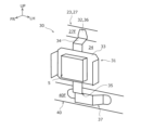
- FIG. 1 is an exploded perspective view illustrating a basic configuration of a vehicle front structure according to an embodiment.
- 1 is a longitudinal cross-sectional view of a vehicle front structure according to an embodiment of the present invention, taken along a center position in a vehicle width direction in a front-rear direction.
- FIG. 2 is a perspective view of the vehicle shown in FIG. 1 with a front bumper removed.
- FIG. 4 is a perspective view of FIG. 3 with the bracket and the in-vehicle device removed. 2 is an enlarged front view of a main portion of a duct member provided in the vehicle front structure of FIG. 1 .
- 13A and 13B are schematic diagrams showing the configuration of a connection portion according to a modified example.
- FIG. 6 is a view for explaining the configuration of a side wall portion of the duct member of FIG. 5 (view taken in the direction of the arrow A in FIG. 5 ).
- FIG. 2 is a cross-sectional view of a main part of the vehicle front structure of FIG. 1 .
- 2 is a perspective view showing a bracket and an on-vehicle device provided in the vehicle front structure of FIG. 1 .
- 10A is a front view of the bracket shown in FIG. 9, (a) is a right side view (viewed in the direction of the arrow B in FIG. 10A), and (c) is a bottom view (viewed in the direction of the arrow C in FIG. 10A).
- the definition of directions is such that the front-to-rear direction (vehicle length direction) is defined based on the forward and backward direction of the vehicle, and the left-to-right direction (vehicle width direction) is defined based on the front-to-rear direction.
- the up-to-down direction is defined based on the state in which the vehicle is stopped on a flat road surface.
- the structure of a vehicle is often formed with approximate left-to-right symmetry (mirror symmetry with respect to a plane including the yaw axis and roll axis passing through the center of gravity of the vehicle), but it does not have to be a completely symmetrical shape.
- the type of vehicle to which the vehicle front structure according to the embodiment is applicable is not particularly limited, and can be applied to, for example, gasoline vehicles, electric vehicles (EVs), hybrid vehicles (Hybrid Electric Vehicles, HEVs), plug-in hybrid vehicles (Plug-in Hybrid Electric Vehicles, PHEVs), etc.
- a plug-in hybrid vehicle is a hybrid vehicle that allows external charging of the battery or external power supply from the battery.
- a plug-in hybrid vehicle is provided with a charging port (inlet) for inserting a charging cable that supplies power from an external charging facility, and an outlet (outlet) for external power supply.
- FIG. 1 is an exploded perspective view showing the configuration of a vehicle front structure 1 according to this embodiment
- FIG. 2 is a longitudinal cross-sectional view cut in the front-rear direction at the center position in the vehicle width direction of the vehicle front structure 1.
- the vehicle front structure 1 is a structure in which air flows into a space 3 (so-called engine room 3) under a bonnet 2 (see FIG. 2) and is a structure that can absorb a load when a vehicle is hit in a frontal collision, and includes a front bumper 10, a first duct member 20 (duct member), and a bracket 30.
- the vehicle front structure 1 of this embodiment further includes a bumper beam 40, a second duct member 50, a third duct member 60, and a heat exchanger 4. Note that in FIG. 1, the second duct member 50, the third duct member 60, and the heat exchanger 4 are omitted from the illustration.
- the front bumper 10 is a bumper component located at the very front of the vehicle, and has an air vent 11 that runs through it in the fore-and-aft direction.
- the air vent 11 is an opening that allows wind (air) from the front of the vehicle to enter the engine compartment 3, and is preferably provided over a wide area of the front bumper 10 (for example, extending to positions close to the left and right headlights, not shown).
- multiple air vents 11 may be provided with gaps between them at the top and bottom, or only one may be provided.
- the first duct member 20 is a member disposed behind (more specifically, immediately behind) the front bumper 10, and has a first air guide port 21 (air guide port) that guides the air flowing in from the air vent 11 rearward.
- the first air guide port 21 is an opening penetrating in the front-to-rear direction, and communicates with at least a portion of the air vent 11 of the front bumper 10.
- the first air guide port 21 is configured so that, when viewed from the front of the vehicle (when viewed from the front), it almost entirely overlaps with the uppermost air vent 11 of the front bumper 10.
- the first duct member 20 is disposed rearward of the upper portion of the front bumper 10.
- the first duct member 20 of this embodiment has a duct function of guiding air from the front to the rear, as well as a function of holding the front bumper 10.
- the first duct member 20 has a holding portion 28 that holds the front bumper 10.
- the holding portion 28 is provided above the first air guide port 21 in the first duct member 20, and has a shape that allows the front bumper 10 to be attached by fasteners such as bolts or screws.
- the left and right ends of the first duct member 20 are fixed to frame members of the vehicle body (for example, left and right side members not shown). The detailed configuration of the first duct member 20 will be described later.
- the bracket 30 is a plate-shaped part that is fixed to at least the front side of the first duct member 20.
- the bracket 30 has the function of fixing the in-vehicle device 5 to the vehicle body.
- the bracket 30 is fixed by connecting the first duct member 20 and the bumper beam 40 (described later), which are arranged at a distance from each other in the vertical direction. That is, one end of the bracket 30 is fixed to the first duct member 20, and the other end of the bracket 30 is fixed to the bumper beam 40.
- the vehicle-mounted device 5 fixed to the bracket 30 is, for example, a detection device such as a millimeter wave radar or a laser radar.
- the vehicle-mounted device 5 for example, emits radar waves (radio waves, laser beams, etc.) toward the front of the vehicle, and detects the presence or absence of an object within this irradiation range and the distance to the object.
- the bracket 30 is positioned as far forward as possible (close to the front bumper 10), and further, that it is provided in the center in the vehicle width direction. The detailed configuration of the bracket 30 will be described later.
- the bumper beam 40 is a skeletal member that connects the left and right side members together, and extends in the vehicle width direction between the first duct member 20 and the second duct member 50 described below.
- the first duct member 20 is disposed above the bumper beam 40
- the second duct member 50 is disposed below the bumper beam 40.
- the second duct member 50 is a member that is disposed rearward of the lower portion of the front bumper 10 and below the first duct member 20 and the bumper beam 40, and has a second air guide port 51 that guides the air that flows in from the air vent 11 rearward.
- the second air guide port 51 is an opening that penetrates in the front-to-rear direction and is configured so that it overlaps almost entirely with the air vent 11 located at the lower portion of the air vents 11 of the front bumper 10.
- the second duct member 50 is attached to the front bumper 10 (so-called assembled), and is not fixed to the first duct member 20 and the bumper beam 40.
- the third duct member 60 is a member that is disposed behind the first duct member 20, the bumper beam 40, and the second duct member 50, and has a vertical dimension (dimension in the vertical direction) that ranges from the upper end of the first duct member 20 to the lower end of the second duct member 50.
- the third duct member 60 is configured so that its upper portion is located behind the first duct member 20, and its lower portion is located behind the second duct member 50.
- the third duct member 60 is provided with two third air intakes 61, 62 that penetrate in the front-rear direction.
- the two third air intakes 61, 62 are arranged side by side vertically.
- One third air intake 61 communicates with the first air intake 21 of the first duct member 20, and the other third air intake 62 communicates with the second air intake 51 of the second duct member 50.
- the third duct member 60 guides the air flowing from each of the first air intake 21 and the second air intake 51 further rearward through the third air intakes 61, 62.
- a heat exchanger 4 is disposed behind the third duct member 60, and the air guided by the three duct members 20, 50, 60 is guided to the heat exchanger 4. In this way, the vehicle front structure 1 of this embodiment has a full duct structure composed of the three duct members 20, 50, 60.
- the heat exchanger 4 is an on-board cooling system device that exchanges thermal energy with the wind (cooling air) introduced from the front, and is fixed to the vehicle body.
- heat exchangers 4 include oil coolers, condensers, and radiators. It is preferable that the heat exchanger 4 be attached to the rear end of the third duct member 60 so that it can receive the wind introduced by the three duct members 20, 50, and 60 without leakage.
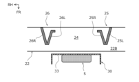
- the first duct member 20 has a frame-shaped portion 22 that forms the first air inlet 21.
- the frame-shaped portion 22 is formed so that the vehicle width dimension (dimension in the vehicle width direction) is larger than the vertical dimension, and is large enough to cover the vent 11 that communicates with the first air inlet 21.
- the frame-shaped portion 22 in this embodiment has an outer shape that is horizontally elongated and approximately rectangular when viewed from the front of the vehicle, and has four walls (upper wall portion 22T, lower wall portion 22B, left wall portion 22L, and right wall portion 22R) that extend in the front-rear direction in the top, bottom, left, and right directions.
- Fig. 5 is a diagram showing the main parts of the first duct member 20, omitting the illustration of the left and right ends (fixed portions to the vehicle body) and the holding portion 28.
- the first duct member 20 further has a connection portion 23 that connects the top and bottom of the frame portion 22 and vertically crosses the first air outlet 21.
- the connection portion 23 has the function of increasing the rigidity of the periphery of the first air outlet 21 of the first duct member 20 (i.e., the frame portion 22).
- the connection portion 23 vertically connects the upper wall portion 22T and the lower wall portion 22B of the frame portion 22.
- the connection portion 23 is also provided in the center of the frame portion 22 in the vehicle width direction.
- the connection portion 23 has an accommodation space 24 that is open at least forward.
- the accommodation space 24 is a space into which the bracket 30 enters when the bracket 30 is displaced rearward.
- the accommodation space 24 functions as an escape space that does not impede the deformation or displacement of the bracket 30, and does not impede the load absorption performance of the front bumper 10 or the bracket 30.
- the accommodation space 24 in this embodiment penetrates in the front-to-rear direction, and is configured not to impede the flow of air from the air vent 11.
- connection portion 23 of this embodiment has a pair of side wall portions 25, 26 that form the left and right side walls of the storage space 24, and a single connection portion 27 that connects the ends of the pair of side wall portions 25, 26.
- the pair of side wall portions 25, 26 are disposed spaced apart from each other in the vehicle width direction and are connected to either the top or bottom of the frame-shaped portion 22.
- the side wall portions 25, 26 of this embodiment are substantially symmetrical (mirror symmetrical) in shape, and each lower end is connected to the bottom side of the frame-shaped portion 22 (i.e., the bottom wall portion 22B).
- the side wall portions 25, 26 divide the first air guide port 21 and the storage space 24 in the vehicle width direction inside the frame-shaped portion 22 (inside the first air guide port 21).
- the connecting portion 27 connecting the left and right side wall portions 25, 26 has a vehicle width dimension larger than the vehicle width dimension of each side wall portion 25, 26, and is connected to the other top or bottom of the frame portion 22 (the side to which the side wall portions 25, 26 are not connected).
- the lower ends of each side wall portion 25, 26 are connected to the lower wall portion 22B of the frame portion 22, so the connecting portion 27 is connected to the upper side of the frame portion 22 (i.e., the upper wall portion 22T) and connects the upper ends of the side wall portions 25, 26 to each other. Therefore, the connecting portion 23 of this embodiment has a shape that is approximately a U-shape turned upside down when viewed from the front of the vehicle, and an approximately rectangular storage space 24 is formed inside the U-shape.
- the connecting portion 27 has the function of increasing the rigidity of the connection portion 23 and the function of reducing the vertical dimension of the storage space 24, and in this embodiment, it also functions as a fixing point for the bracket 30 described below. If the connecting portion 27 does not exist, that is, if the storage space 24 is formed only by a pair of side wall portions 25, 26, the vertical dimension of the side wall portions 25, 26 may become long depending on the vertical dimension of the first air guide port 21, and it may be difficult to increase the rigidity of the frame-shaped portion 22. In contrast, by providing the connecting portion 27, the vertical dimension of the side wall portions 25, 26 is kept to the minimum necessary to form the storage space 24, and the connecting portion 27 and the side wall portions 25, 26 can improve the rigidity of the frame-shaped portion 22.
- the connecting portion 27 of this embodiment does not have a constant vehicle width in the vertical direction, but the minimum value W3 of the vehicle width of the connecting portion 27 is set to be larger than the vehicle width W2 of each side wall portion 25, 26.
- the connecting portion 27 shown in Figure 5 has a lower end surface 27B that connects from the left side surface 25L of the left wall portion 25 to the right side surface 26R of the right wall portion 26, and the left and right side surfaces 27L, 27R are inclined in a direction approaching each other toward the upper side and then extend vertically.
- the left side surface 27L of the connecting portion 27 is located to the right of the left side surface 25L of the left side wall portion 25, and the right side surface 27R of the connecting portion 27 is located to the left of the right side surface 26R of the right side wall portion 26.
- the minimum vehicle width dimension W3 of the connecting portion 27 is configured to be shorter than the vehicle width dimension W1 of the connection portion 23 (the vehicle width dimension from the left side surface 25L of the left side wall portion 25 to the right side surface 26R of the right side wall portion 26), so that the area of the first air intake vents 21 on both the left and right sides of the connection portion 23 is expanded by the area indicated by the dotted pattern in Figure 5.
- the configuration of the connecting portion 27 is not limited to that shown in FIG. 5.
- the connecting portion 27 may be a horizontally long rectangular shape when viewed from the front of the vehicle.
- the vehicle width dimension of the connecting portion 27 is constant in the vertical direction. Therefore, in order to obtain the advantage of expanding the area of the first air guide port 21 as in the configuration of FIG. 5, the left and right side surfaces 27L, 27R of the connecting portion 27 may be shifted inward in the vehicle width direction (so as to form a step) with respect to the surfaces (left side surface 25L, right side surface 26R) of the left and right side wall portions 25, 26 facing outward in the vehicle width direction.
- the vehicle width dimension W3 of the connecting portion 27 becomes shorter than the vehicle width dimension W1 of the connection portion 23, and the area of the first air guide port 21 is expanded as in FIG. 5.
- the connecting portion 27 may be trapezoidal when viewed from the front of the vehicle. Even in this case, the area of the first air guide port 21 is expanded as in FIG. 5.
- the leading edges 25F, 26F of the side walls 25, 26 are inclined so that they are positioned further rearward as they go downward in a side view of the vehicle (as seen from the side). This creates space in front of the lower parts of the side walls 25, 26, and prevents interference with surrounding components.
- the trailing edges of the side walls 25, 26 are not inclined relative to the vertical direction, so the front-to-rear dimensions (dimensions in the front-to-rear direction) of the side walls 25, 26 are smaller as they go downward, but the trailing edges may also be inclined in the same way as the leading edges 25F, 26F.
- the opposing side surfaces of the pair of side walls 25, 26, i.e., the right side surface 25R of the left wall portion 25 and the left side surface 26L of the right wall portion 26, are inclined so as to approach each other toward the rear.
- the width (vehicle width dimension) of the storage space 24 becomes smaller toward the rear.
- the side walls 25, 26 do not have to be V-shaped in cross section.
- only the right side surface 25R of the left wall portion 25 i.e., the side surface facing the storage space 24 in the vehicle width direction
- FIG. 9 is a perspective view showing the bracket 30 and the on-board device 5 included in the vehicle front structure 1 according to this embodiment.
- Figs. 10(a) to 10(c) are a front view, a left side view, and a bottom view of the bracket 30, respectively.
- the bracket 30 is disposed so as to overlap with the above-mentioned accommodation space 24 in a front view of the vehicle. It is preferable that the entire bracket 30 overlaps with the accommodation space 24 in a front view of the vehicle, but it is sufficient that at least a part of the bracket 30 overlaps with the accommodation space 24 and enters the accommodation space 24 when the bracket 30 is displaced rearward.
- the bracket 30 of this embodiment has one end (upper end) fixed to the first duct member 20 and the other end (lower end) fixed to the bumper beam 40, and is extended in the vertical direction. Specifically, one end of the bracket 30 is fixed to the connection portion 23 (more specifically, the front surface 27F of the connecting portion 27), and the other end of the bracket 30 is fixed to the front surface 40F of the bumper beam 40. Therefore, the bracket 30 is disposed so as to protrude forward from the connection portion 23.
- the fixing point of the bracket 30 to the first duct member 20 is referred to as the fixing surface 32.
- the bracket 30 is mechanically fastened and fixed to this fixing surface 32, for example, by bolts, screws, etc.
- the bracket 30 has an equipment mounting portion 31 including a top plate 33 to which the in-vehicle equipment 5 is fixed, and an upper vertical wall 34 and a lower vertical wall 35 extending rearward from the upper and lower edges of the top plate 33, respectively.
- the top plate 33 is the main surface portion (flat portion) with the largest area of the bracket 30, and is arranged toward the lower side of the frame-shaped portion 22 (closer to the lower wall portion 22B than to the upper wall portion 22T) as shown in FIG. 3.
- the top plate 33 is spaced forward from the fixing surface 32 for the connection portion 23 and extends in the vertical direction and the vehicle width direction.
- the top plate 33 has a generally rectangular top plate fixing surface 33A and extension portions 33B extending upward and downward from the centers of the upper and lower edges of the top plate fixing surface 33A.
- the top board fixing surface 33A is formed in a generally rectangular shape that is equal to or slightly larger than the outer shape of the frame of the in-vehicle device 5.
- the top board fixing surface 33A may be provided with a hole for fixing the in-vehicle device 5, an opening through which the wiring of the in-vehicle device 5 is inserted, or the like.
- the extension portion 33B is not essential and may be omitted.
- the equipment mounting portion 31 of this embodiment has an upper vertical wall 34 and a lower vertical wall 35 that extend diagonally relative to the top plate 33 so that they are spaced apart toward the rear, forming a hat shape in side view.
- the top plate 33 forms the top surface portion of the hat shape.
- the upper vertical wall 34 is formed continuously from the upper edge of the upper extension 33B of the top plate 33 toward the rear and slightly upward.
- the lower vertical wall 35 is formed continuously from the lower edge of the lower extension 33B of the top plate 33 toward the rear and slightly downward.
- the bracket 30 has a flange 36 formed continuously upward from the upper edge of the upper vertical wall 34.
- the flange 36 is a surface portion that constitutes the fixing surface 32 described above.
- the bracket 30 of this embodiment has a lower hat portion 37 having a hat shape that opens to the rear when viewed from above (or below) the vehicle.
- the lower hat portion 37 has a second top plate 37A, a left vertical wall 37B, a right vertical wall 37C, a left flange 37D, and a right flange 37E.
- the second top plate 37A is a surface portion provided on the lower edge of the lower vertical wall 35 of the equipment mounting portion 31, and is provided continuously downward from this lower edge and extends in the vertical direction and the vehicle width direction. As shown in FIG.
- the second top plate 37A forms the top surface portion of the hat shape, and is disposed forward and spaced from the fixing surface (referred to as the second fixing surface 38) of the bracket 30 to the bumper beam 40.
- the equipment mounting portion 31 forms an upper hat structure in the vertical direction (vertical direction)
- the lower hat portion 37 forms a lower hat structure in the horizontal direction (vehicle width direction).
- the left vertical wall 37B is formed continuously from the left edge of the second top plate 37A toward the rear and left (outside the vehicle).
- the right vertical wall 37C is formed continuously from the right end of the second top plate 37A toward the rear and right (outside the vehicle).
- the left vertical wall 37B and the right vertical wall 37C both extend obliquely with respect to the second top plate 37A so as to be spaced apart from each other when viewed from above (or below) the vehicle.
- the left flange 37D is a surface portion formed continuously from the left edge of the left vertical wall 37B toward the left (outside the vehicle) and constitutes the second fixing surface 38.
- the right flange 37E is a surface portion formed continuously from the right edge of the right vertical wall 37C toward the right (outside the vehicle) and constitutes the second fixing surface 38.
- the bracket 30 of this embodiment is formed from a single piece of sheet metal. That is, in the bracket 30, the equipment mounting portion 31 and the lower hat portion 37 are provided as an integral unit. Note that the bracket may also be one in which the equipment mounting portion 31 and the lower hat portion 37 are provided as separate bodies and integrated (joined, welded, etc.).
- the first duct member 20 disposed behind the front bumper 10 has a frame-shaped portion 22 that forms the first air guide port 21, and a connection portion 23 that connects the top and bottom of the frame-shaped portion 22 and vertically crosses the first air guide port 21.
- the connection portion 23 can ensure the rigidity of the first duct member 20 around the first air guide port 21 (i.e., the frame-shaped portion 22).
- the bracket 30 is disposed in front of the first duct member 20 (i.e., between the front bumper 10 and the first duct member 20).
- the connection portion 23 has an accommodation space 24 that is open at least forward, and the bracket 30 is fixed to at least the front side of the first duct member 20 and disposed so as to overlap the accommodation space 24 when viewed from the front of the vehicle. This makes it difficult for the positional relationship between the bracket 30 and the first duct member 20 to shift when the bracket 30 is displaced rearward, and also allows the bracket 30 to enter the accommodation space 24 located behind it.
- the bracket 30 deforms and displaces rearward (backward) in conjunction with the rearward displacement of the front bumper 10 in the event of a frontal collision of the vehicle, the likelihood of this deformation or displacement being hindered by the connection portion 23 is significantly reduced.
- the load absorption function during a vehicle collision is not hindered, and the load input to the vehicle can be absorbed by the deformation and displacement of the front bumper 10 and bracket 30.
- the load on the pedestrian can be alleviated, ensuring pedestrian protection performance.
- connection portion 23 has a pair of side wall portions 25, 26 and a connecting portion 27 that connects the ends of these portions, connecting the top and bottom of the frame-shaped portion 22.
- the connection portion 23 is configured to branch into two in the middle in the vertical direction when viewed from the front of the vehicle, and has a storage space 24 inside this branch.
- the rigidity of the connecting portion 23 can be increased, and thus the rigidity around the first air outlet 21 can be further increased.
- the rigidity required for the first duct member 20 can be ensured by the connection portion 23.
- the first duct member 20 holds the front bumper 10
- the left side surface 27L of the connecting portion 27 is located to the right of the left side surface 25L of the left side wall portion 25, and the right side surface 27R of the connecting portion 27 is located to the left of the right side surface 26R of the right side wall portion 26.
- This configuration makes it possible to expand the area of the first air intake ports 21 present on both the left and right sides of the connection portion 23 by the area shown by the dotted pattern in FIG. 5. This ensures the flow rate of the air flowing in from the air vent 11, and when a heat exchanger 4 is disposed behind the first duct member 20, the cooling performance of the heat exchanger 4 can be improved.
- the front edges 25F, 26F of the side walls 25, 26 are inclined so that they are positioned further rearward as viewed from the side of the vehicle, so that the bracket 30 can be easily accommodated in the accommodation space 24 when it is retracted.
- the connecting portion 27 is connected to the upper side of the frame-shaped portion 22 and connects the upper ends of the pair of side walls 25, 26, and the main surface portion (i.e., the top plate 33) of the bracket 30 having the largest area is positioned toward the lower side of the frame-shaped portion 22, the frame-shaped portion 22 will have an inverted U-shape, and the main surface portion (top plate 33) of the bracket 30 will be disposed close to the lower wall portion 22 of the frame-shaped portion 22.
- the bracket 30 when a load from the front is transmitted to the bracket 30, the bracket 30 is likely to deform so as to tilt backward (the upper part of the bracket 30 is set back more than the lower part).
- the front edges 25F, 26F of the side walls 25, 26 are inclined so that they are positioned further rearward as they go downward (in other words, the upper parts of the side walls 25, 26 protrude further forward than the lower parts), so the upper parts of the side walls 25, 26 can quickly accommodate the bracket 30 that has been set back.
- the front edges 25F, 26F of the side walls 25, 26 are inclined so that they are positioned further rearward as they go downward when viewed from the side of the vehicle, forming a space below the side walls 25, 26. This makes it possible to avoid interference with surrounding parts and structures, including the bracket 30, and does not prevent the bracket 30 from retracting. This makes it easier for the bracket 30 to enter the storage space 24 when displaced rearward, ensuring load absorption performance.
- each side wall 25, 26 has a V-shaped cross section that opens to the rear, so that the opposing side surfaces 25R, 26L are inclined so that they approach each other toward the rear and have a shape that widens toward the front.
- the bracket 30 when focusing on the storage space 24, if the storage space 24 has a tapered shape in which the front side is wide and the vehicle width dimension becomes smaller toward the rear, it is possible for the bracket 30 to easily enter the storage space 24 when displaced rearward. This makes it possible to further ensure load absorption performance.
- each side wall 25, 26 has a V-shaped cross section, and this effect is obtained by having at least one of the pair of side walls 25, 26 have a side surface on the storage space 24 side in the vehicle width direction inclined so that it is located closer to the storage space 24 side in the vehicle width direction toward the rear.
- connection portion 23 is provided in the center of the frame portion 22 in the vehicle width direction, the center of the frame portion 22 in the vehicle width direction can be reinforced by the connection portion 23 while minimizing the reduction in the area of the first air intake port 21, thereby contributing to improved rigidity.
- the frame-shaped portion 22 described above is configured so that its width dimension is longer than its vertical dimension, and the bracket 30 has one end fixed to the connection portion 23 and is extended in the vertical direction. That is, the first air guide port 21 of the first duct member 20 is formed wide in the vehicle width direction, which makes it easier for the air to flow rearward.
- the connection portion 23 reduces the area of the first air guide port 21, by fixing the bracket 30 to this connection portion 23, the area of the first air guide port 21 is not further narrowed by the bracket 30, and the area of the first air guide port 21 can be secured to be larger than in a configuration in which the bracket 30 extends in the vehicle width direction. This ensures a flow rate of cooling air, and when a heat exchanger 4 is disposed behind the first duct member 20, the cooling performance of the heat exchanger 4 can be improved.
- the above-mentioned bracket 30 has a top plate 33 (main surface) to which the in-vehicle device 5 is fixed, and an equipment mounting portion 31 including an upper vertical wall 34 and a lower vertical wall 35 extending rearward from the upper and lower edges of the top plate 33, respectively.
- This equipment mounting portion 31 allows the in-vehicle device 5 to be positioned further forward (closer to the front bumper 10).
- the load on the pedestrian may be too large if the vehicle collides head-on with the pedestrian.
- the equipment mounting portion 31 of the bracket 30 is configured to be easily deformed rearward when a load is input, and there is an accommodation space 24 behind the bracket 30, so that the in-vehicle device 5 can be released rearward, and the load on the pedestrian (for example, the impact on the legs) can be mitigated. Therefore, the pedestrian protection performance during a vehicle collision can be improved.
- the upper vertical wall 34 and the lower vertical wall 35 extend diagonally relative to the top plate 33 so that they become increasingly separated from each other as they go rearward, forming a hat shape in side view.
- each vertical wall 34, 35 into a hat shape rather than perpendicular to the top plate 33, when a load (impact) acts from the front, the upper and lower vertical walls 34, 35 can easily deform without being stiffened. This can further improve pedestrian protection performance.
- bracket 30 Since the above-described bracket 30 is formed from a single piece of metal plate, the bracket 30 can be manufactured inexpensively and simply. (11) Furthermore, since the above-mentioned storage space 24 is penetrated in the front-to-rear direction, wind can pass through the storage space 24, which prevents the original function of the first duct member 20 (the function of guiding wind) from being impaired.
- the above-mentioned vehicle front structure 1 is an example and is not limited to the above.
- the above-mentioned first duct member 20 has a holding portion 28 that holds the front bumper 10, but the first duct member 20 only needs to have at least a duct function, and the holding portion 28 may be omitted and the front bumper 10 may be held in another portion.
- the shape of the frame-shaped portion 22 of the first duct member 20 is not limited to the above-mentioned rectangular shape.
- the frame-shaped portion 22 only needs to form at least an air guide port (first air guide port 21) that guides the wind flowing in from the air vent 11 rearward.
- connection portion 23 is also one example.
- a pair of side wall portions may be connected to the upper side of the frame portion 22, and the connecting portion may be connected to the lower side of the frame portion 22 and connect the lower ends of the pair of side wall portions together.
- the left and right side surfaces of the connecting portion may be flush with the outer side surfaces of the left and right side wall portions in the vehicle width direction.
- the front edges 25F, 26F of the pair of side wall portions 25, 26 forming the storage space 24 are inclined so that they are positioned further rearward as they are lower, but for example, they may be inclined so that they are positioned further rearward as they are upper, or they may not be inclined (they may extend vertically).
- the bracket 30 may be prone to deformation behavior such that it tilts forward (the amount of setback of the lower part of the bracket 30 is greater than the amount of setback of the upper part).
- the pair of side walls 25, 26 of the first duct member 20 described above have a V-shaped cross section that opens to the rear, but for example, the outer side surfaces 25L, 26R in the vehicle width direction that do not face each other are not essential and do not have to be inclined as described above. Even in this case, the area expansion effect of the first air guide port 21 can be obtained.
- the storage space 24 does not have to be formed by a pair of side walls and a connecting portion.
- the connecting portion may be omitted and the storage space may be formed only by a pair of side walls.
- the shape of the storage space is not limited to the rectangular shape described above. In addition, the storage space may not penetrate in the front-rear direction (i.e., a recess with a bottom surface at the rear).
- the arrangement and number of the connection portions 23 are also not limited to those described above, and for example, multiple connection portions may be arranged at intervals in the vehicle width direction.
- the bracket 30 may have another function.
- the specific shape of the bracket 30 is not limited to that described above.
- the above-mentioned bracket 30 has the lower hat portion 37 only at the lower end of the device mounting portion 31, but the lower hat portion 37 may be only at the upper end of the device mounting portion 31, or may be at both the upper and lower ends of the device mounting portion.
- the lower hat portion 37 is provided at least at the top or bottom, there is an advantage that the bracket 30 becomes more easily deformed when a load (impact) is applied from a direction other than the front, and pedestrian protection performance can be further improved.
- the lower hat portion 31 is not essential and can be omitted.
- the equipment mounting portion 31 does not have to be hat-shaped in side view, and each vertical wall 34, 35 may be provided perpendicular to the top plate 33.
- the bracket 30 described above has one end fixed to the connection portion 23 (more specifically, the front surface 27F of the coupling portion 27) and the other end fixed to the front surface 40F of the bumper beam 40, but the fixing destination of the bracket is not limited to this. It is sufficient that the bracket is fixed at least to the front side of the duct member (first duct member 20).
- the bumper beam 40, the second duct member 50, and the third duct member 60 are not essential components and may be omitted.
- This invention can be used in the vehicle manufacturing industry where the vehicle front structure is applied.
- Vehicle front structure 10
- Front bumper 11 Air vent 20
- First duct member (duct member) 21
- First air guide port (air guide port) 22
- Frame-shaped portion 23
- Connection portion 24 Storage space 25
- Left side wall portion (side wall portion) 25F: front edge; 25L: left side; 25R: right side (side surface on the storage space side); 26
- Right side wall (side wall) 26F front edge 26L left side surface (side surface on the storage space side) 26R Right side surface 27 Connecting portion 27L Left side surface 27R of connecting portion Right side surface 28 Holding portion 30
- Equipment mounting portion 32
- Fixing surface 33
- Top plate 34 Upper vertical wall 35
- Lower vertical wall H1 Vertical dimension H2 of first air outlet Vertical dimension H3 of side wall portion
- Vertical dimension W1 of connecting portion Vehicle width dimension W2 of connection portion
- Vehicle width dimension W3 of side wall portion Minimum vehicle width dimension of connecting portion
Landscapes
- Engineering & Computer Science (AREA)
- Chemical & Material Sciences (AREA)
- Combustion & Propulsion (AREA)
- Transportation (AREA)
- Mechanical Engineering (AREA)
- Body Structure For Vehicles (AREA)
Priority Applications (2)
| Application Number | Priority Date | Filing Date | Title |
|---|---|---|---|
| JP2025539047A JPWO2025032784A1 (https=) | 2023-08-09 | 2023-08-09 | |
| PCT/JP2023/029187 WO2025032784A1 (ja) | 2023-08-09 | 2023-08-09 | 車両前部構造 |
Applications Claiming Priority (1)
| Application Number | Priority Date | Filing Date | Title |
|---|---|---|---|
| PCT/JP2023/029187 WO2025032784A1 (ja) | 2023-08-09 | 2023-08-09 | 車両前部構造 |
Publications (1)
| Publication Number | Publication Date |
|---|---|
| WO2025032784A1 true WO2025032784A1 (ja) | 2025-02-13 |
Family
ID=94533769
Family Applications (1)
| Application Number | Title | Priority Date | Filing Date |
|---|---|---|---|
| PCT/JP2023/029187 Pending WO2025032784A1 (ja) | 2023-08-09 | 2023-08-09 | 車両前部構造 |
Country Status (2)
| Country | Link |
|---|---|
| JP (1) | JPWO2025032784A1 (https=) |
| WO (1) | WO2025032784A1 (https=) |
Citations (5)
| Publication number | Priority date | Publication date | Assignee | Title |
|---|---|---|---|---|
| US20140354465A1 (en) * | 2013-05-28 | 2014-12-04 | Hyundai Motor Company | Radar apparatus for vehicle |
| JP2016132276A (ja) * | 2015-01-16 | 2016-07-25 | マツダ株式会社 | 車両の前部構造 |
| JP2018134936A (ja) * | 2017-02-21 | 2018-08-30 | 三菱自動車工業株式会社 | レーダー取付構造 |
| JP2019167015A (ja) * | 2018-03-23 | 2019-10-03 | 本田技研工業株式会社 | 車体前部構造 |
| JP2020083117A (ja) * | 2018-11-27 | 2020-06-04 | トヨタ自動車株式会社 | 車両前部構造 |
-
2023
- 2023-08-09 WO PCT/JP2023/029187 patent/WO2025032784A1/ja active Pending
- 2023-08-09 JP JP2025539047A patent/JPWO2025032784A1/ja active Pending
Patent Citations (5)
| Publication number | Priority date | Publication date | Assignee | Title |
|---|---|---|---|---|
| US20140354465A1 (en) * | 2013-05-28 | 2014-12-04 | Hyundai Motor Company | Radar apparatus for vehicle |
| JP2016132276A (ja) * | 2015-01-16 | 2016-07-25 | マツダ株式会社 | 車両の前部構造 |
| JP2018134936A (ja) * | 2017-02-21 | 2018-08-30 | 三菱自動車工業株式会社 | レーダー取付構造 |
| JP2019167015A (ja) * | 2018-03-23 | 2019-10-03 | 本田技研工業株式会社 | 車体前部構造 |
| JP2020083117A (ja) * | 2018-11-27 | 2020-06-04 | トヨタ自動車株式会社 | 車両前部構造 |
Also Published As
| Publication number | Publication date |
|---|---|
| JPWO2025032784A1 (https=) | 2025-02-13 |
Similar Documents
| Publication | Publication Date | Title |
|---|---|---|
| US11001308B2 (en) | Vehicle front structure | |
| JP5543999B2 (ja) | 車体前部構造 | |
| US9061585B2 (en) | Cooling air introduction apparatus for vehicle | |
| US6540037B2 (en) | Vehicle front end panel | |
| US9242676B2 (en) | Front vehicle body reinforcing structure | |
| CN113212151B (zh) | 车辆部件的支承构造 | |
| CN113135154A (zh) | 车辆构造 | |
| US20220097767A1 (en) | Vehicle Impact Energy Absorption System | |
| CN114072300A (zh) | 电子设备模块相对于车辆的搭载构造 | |
| JP2014069695A (ja) | 車体前部構造 | |
| JP2023148542A (ja) | 車体前部構造 | |
| US20250178673A1 (en) | Vehicle frame structure | |
| CN114194297A (zh) | 车辆碰撞能量吸收系统和车辆 | |
| CN119058827A (zh) | 车辆前部结构 | |
| WO2025032784A1 (ja) | 車両前部構造 | |
| JP2008049735A (ja) | 車体前部構造 | |
| JP2008049935A (ja) | 車体前部構造 | |
| CN212098398U (zh) | 车辆用电气设备的保护结构 | |
| JP5746542B2 (ja) | 車両の冷却風導入装置 | |
| CN112572150A (zh) | 蓄电池保护构造 | |
| JP5573342B2 (ja) | 車両の前部車体構造 | |
| WO2023105757A1 (ja) | 電気機器の取付構造 | |
| JP7238627B2 (ja) | 車両用電気機器の保護構造 | |
| JP2021027010A (ja) | 車両用バッテリパック | |
| JP7472531B2 (ja) | 車両前部構造 |
Legal Events
| Date | Code | Title | Description |
|---|---|---|---|
| 121 | Ep: the epo has been informed by wipo that ep was designated in this application |
Ref document number: 23948501 Country of ref document: EP Kind code of ref document: A1 |
|
| ENP | Entry into the national phase |
Ref document number: 2025539047 Country of ref document: JP Kind code of ref document: A |
|
| WWE | Wipo information: entry into national phase |
Ref document number: 2025539047 Country of ref document: JP |
|
| WWE | Wipo information: entry into national phase |
Ref document number: 2601000393 Country of ref document: TH |
|
| NENP | Non-entry into the national phase |
Ref country code: DE |