WO2025013298A1 - 配線基板の製造方法、半導体装置の製造方法、配線基板、及び、半導体装置 - Google Patents
配線基板の製造方法、半導体装置の製造方法、配線基板、及び、半導体装置 Download PDFInfo
- Publication number
- WO2025013298A1 WO2025013298A1 PCT/JP2023/025947 JP2023025947W WO2025013298A1 WO 2025013298 A1 WO2025013298 A1 WO 2025013298A1 JP 2023025947 W JP2023025947 W JP 2023025947W WO 2025013298 A1 WO2025013298 A1 WO 2025013298A1
- Authority
- WO
- WIPO (PCT)
- Prior art keywords
- wiring
- electrode
- dummy
- insulating layer
- wiring board
- Prior art date
- Legal status (The legal status is an assumption and is not a legal conclusion. Google has not performed a legal analysis and makes no representation as to the accuracy of the status listed.)
- Pending
Links
Images





Classifications
-
- H—ELECTRICITY
- H10—SEMICONDUCTOR DEVICES; ELECTRIC SOLID-STATE DEVICES NOT OTHERWISE PROVIDED FOR
- H10W—GENERIC PACKAGES, INTERCONNECTIONS, CONNECTORS OR OTHER CONSTRUCTIONAL DETAILS OF DEVICES COVERED BY CLASS H10
- H10W70/00—Package substrates; Interposers; Redistribution layers [RDL]
- H10W70/60—Insulating or insulated package substrates; Interposers; Redistribution layers
Definitions
- This disclosure relates to a method for manufacturing a wiring board, a method for manufacturing a semiconductor device, a wiring board, and a semiconductor device.
- a packaging technology using an organic substrate with high-density wiring organic interposer
- a fan-out type packaging technology (FO-WLP) with through-mold vias TMV
- TSV through-mold vias
- TSV through-silicon vias
- a packaging technology using chips embedded in a substrate for inter-chip transmission and the like
- organic interposers and FO-WLP when semiconductor chips are mounted in parallel, a fine wiring layer is required to achieve high-density conduction (see Patent Document 2).
- JP 2011-029287 A US Patent Application Publication No. 2011/0221071 JP 2017-157666 A
- TMV Through Mold Via
- ECTC Electronic Components and Technology Conference
- eWLB-PoP Embedded Wafer Level PoP
- the present disclosure aims to provide a method for manufacturing a wiring board, a method for manufacturing a semiconductor device, a wiring board, and a semiconductor device that can prevent wiring breakage due to cracks.
- the present disclosure provides a method for manufacturing a wiring board.
- the method for manufacturing a wiring board includes the steps of forming a first insulating layer on a support substrate, forming a resist layer on the first insulating layer, forming a plurality of openings in the resist layer, including a first opening and a second opening for wiring electrodes and a third opening for a dummy electrode, forming a first wiring electrode and a second wiring electrode in the first opening and the second opening, respectively, forming a first dummy electrode in the third opening, removing the resist layer after forming the first wiring electrode, the second wiring electrode, and the first dummy electrode, and forming a second insulating layer on the first insulating layer so as to cover at least the first dummy electrode.
- the surfaces of the first wiring electrode and the second wiring electrode are exposed from the second insulating layer, and at least a portion of the first dummy electrode is located between the first wiring electrode and the second wiring electrode.
- this method of manufacturing a wiring board makes it possible to provide a wiring board that prevents wiring from breaking due to cracks.
- the width of the first dummy electrode may be 10 ⁇ m or more in a direction from the center of the first wiring electrode toward the outside.
- the first dummy electrode can reliably suppress the extension of cracks that occur in the insulating layer near the first wiring electrode or the second wiring electrode. This makes it possible to provide a wiring board that more reliably prevents wiring breakage due to cracks.
- the first dummy electrode may have a portion whose maximum width in the direction from the center of the first wiring electrode toward the outside is 100 ⁇ m or more. In this case, it is possible to reliably prevent cracks from occurring in the insulating layer near the first wiring electrode or the second wiring electrode, or to more reliably prevent the extension of cracks that do occur. This makes it possible to provide a wiring board that more reliably prevents wiring breakage due to cracks.
- the distance between the first wiring electrode and the first dummy electrode may be 50 ⁇ m or more. In this case, insulation between the first wiring electrode and the first dummy electrode can be ensured. This makes it possible to provide a wiring board in which the first dummy electrode does not impede the electrical conductivity of the first wiring electrode.
- a fourth opening for a dummy electrode may be further formed, and this manufacturing method may further include a step of forming a second dummy electrode in the fourth opening. At least a portion of the first dummy electrode and the second dummy electrode may be formed between the first wiring electrode and the second wiring electrode, with the first dummy electrode located on the first wiring electrode side and the second dummy electrode located on the second wiring electrode side.
- the second dummy electrode in addition to the first dummy electrode, it is possible to suppress the occurrence of cracks near the second wiring electrode or to suppress the extension of cracks that have occurred near the second wiring electrode. This makes it possible to provide a wiring board that further suppresses breakage of wiring due to cracks.
- the method for manufacturing a wiring board according to [5] above may further include a step of forming a wiring section between the first dummy electrode and the second dummy electrode, and the wiring section may have a plurality of wirings of 10 ⁇ m or less. In this case, it is possible to provide a wiring board in which desired wiring is formed between the first wiring electrode and the second wiring electrode.
- the first dummy electrode and the second dummy electrode may be connected by a conductive material.
- the first dummy electrode may be formed to surround the first wiring electrode when viewed in a plan view.
- a wiring board that suppresses the occurrence or extension of cracks in any direction near the first wiring electrode.
- the second dummy electrode may be formed to surround the second wiring electrode when viewed in a plan view. In this case, the same effect as the first dummy electrode can be achieved.
- the first wiring electrode may have a portion that is curved when viewed in a planar view
- the first dummy electrode may have a portion that is curved when viewed in a planar view.
- the first dummy electrode may have a thickness equal to or more than half the thickness of the second insulating layer. In this case, it is possible to provide a wiring board in which the first dummy electrode reliably prevents cracks originating near the first wiring electrode or the second wiring electrode from extending.
- the second dummy electrode may have a thickness equal to or more than half the thickness of the second insulating layer. In this case, the same effect as the first dummy electrode can be achieved.
- the present disclosure provides a method for manufacturing a semiconductor device.
- This method for manufacturing a semiconductor device includes the steps of preparing a wiring board manufactured by any one of the wiring board manufacturing methods [1] to [10] above, and mounting a semiconductor chip on the wiring board using a conductive member.
- this method of manufacturing a semiconductor device makes it possible to provide a semiconductor device that suppresses the occurrence of cracks originating near the first wiring electrode and the second wiring electrode, or suppresses the extension of cracks that do occur, on a wiring substrate on which a semiconductor chip is mounted. This makes it possible to provide a semiconductor device in which breakage of wiring due to cracks is prevented.
- a first conductive member and a second conductive member which are conductive members, may be disposed on the first wiring electrode and the second wiring electrode of the wiring board, respectively, and a semiconductor chip may be mounted on the first conductive member and the second conductive member, and the connection terminals of the semiconductor chip may be connected to the first wiring electrode and the second wiring electrode via the first conductive member and the second conductive member, and the semiconductor chip may be mounted on the surface of the wiring board on which the first dummy electrode is formed.
- the present disclosure provides a wiring board as yet another aspect.
- the wiring board includes a support substrate, a first insulating layer provided on the support substrate, a second insulating layer provided on the first insulating layer, a first wiring electrode and a second wiring electrode provided in the second insulating layer, and a first dummy electrode provided in the second insulating layer.
- the surfaces of the first wiring electrode and the second wiring electrode are exposed from the second insulating layer, and at least a portion of the first dummy electrode is located between the first wiring electrode and the second wiring electrode.
- this wiring board at least a portion of the first dummy electrode that is not connected to a semiconductor chip or the like is positioned between the first wiring electrode and the second wiring electrode that are connected to the semiconductor chip or the like. In this case, even if a temperature change or the like occurs in a semiconductor device using this wiring board, it is possible to suppress the occurrence of cracks in the second insulating layer or the like, or to suppress the extension of any cracks that do occur. As a result, in a semiconductor device using this wiring board, wiring such as the first wiring electrode or the second wiring electrode is prevented from being broken due to temperature changes.
- the width of the first dummy electrode may be 10 ⁇ m or more in the direction from the center of the first wiring electrode to the outside.
- the first dummy electrode can reliably suppress the extension of cracks that occur in the insulating layer near the first wiring electrode or the second wiring electrode. This makes it possible to more reliably prevent the wiring from being broken by cracks.
- the wiring board of [13] or [14] above may further include a second dummy electrode provided in the second insulating layer, and the first dummy electrode and the second dummy electrode may be arranged such that at least a portion of each electrode is located between the first wiring electrode and the second wiring electrode, with the first dummy electrode located on the first wiring electrode side and the second dummy electrode located on the second wiring electrode side.
- the second dummy electrode can suppress the occurrence of cracks near the second wiring electrode or suppress the extension of cracks that have occurred near the second wiring electrode. As a result, this wiring board can more reliably prevent wiring breakage due to cracks.
- the first dummy electrode may be formed to surround the first wiring electrode when viewed in a plan view. In this case, it is possible to suppress the occurrence or extension of cracks in any direction near the first wiring electrode. Furthermore, by providing a dummy electrode to surround the wiring electrode, it is possible to provide a wiring board with a layout that does not hinder the improvement of the mounting density of the wiring electrodes.
- the second dummy electrode may be formed to surround the second wiring electrode when viewed in a plan view.
- the present disclosure provides a semiconductor device.
- This semiconductor device includes a wiring board in any of the forms described above in [13] to [16], a first conductive portion and a second conductive portion provided on the first wiring electrode and the second wiring electrode, respectively, on the wiring board, and a semiconductor chip mounted on the second insulating layer so as to be conductive to the first conductive portion and the second conductive portion. In this case, it is possible to prevent the wiring from breaking due to cracks, as described above.
- FIG. 1 is a cross-sectional view showing an example of a semiconductor device in which a semiconductor chip is mounted on a wiring substrate.
- 2 is a plan view showing the upper surface side of the wiring substrate of the semiconductor device shown in FIG. 3A to 3C are diagrams showing a method of manufacturing a wiring board which constitutes the semiconductor device shown in FIG.
- FIG. 4 is a diagram showing a method for producing a wiring board, showing a step following the step shown in FIG.
- FIG. 5 is a diagram showing a method of manufacturing a wiring board, showing a step following the step shown in FIG. 6A to 6C are diagrams showing a method for manufacturing the semiconductor device shown in FIG.
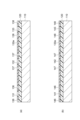
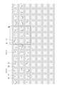
- FIG. 7 is a diagram showing how the extension of a crack occurring in a wiring board (semiconductor device) is stopped by a dummy electrode.
- FIG. 8 is an enlarged view of a portion VIII of FIG.
- the term “layer” includes structures with shapes formed over the entire surface as well as structures with shapes formed on only a portion of the surface when observed in a plan view.
- the term “process” includes not only independent processes, but also processes that cannot be clearly distinguished from other processes as long as the intended effect of the process is achieved.
- numerical ranges indicated using “A-B” indicate ranges that include the numerical values A and B written before and after "-" as the minimum and maximum values, respectively.
- the semiconductor device 1 includes a semiconductor chip 10, solder bumps 21, 22, and 23 (first conductive portion and second conductive portion), an insulating resin layer 25, and a wiring substrate 30.
- the semiconductor chip 10 is, for example, a logic IC or a memory IC, and is mounted on the wiring board 30 via solder bumps 21-23. Each connection terminal 11, 12, 13 of the semiconductor chip 10 is connected to a wiring electrode 70 of the wiring board 30 via the solder bumps 21-23.
- An insulating resin layer 25 formed from a sealing resin such as an underfill agent is provided between the semiconductor chip 10 and the wiring board 30.
- the wiring board 30 includes a support substrate 40, a first insulating layer 50, a second insulating layer 60, wiring electrodes 71, 72, and 73 (first wiring electrode, second wiring electrode), and dummy electrodes 81, 82, and 83 (first dummy electrode, second dummy electrode).
- the wiring board 30 may further include a wiring section 90.
- the wiring section 90 is a section in which various types of wiring are provided.
- the support substrate 40 is not particularly limited, but may be, for example, a silicon substrate, a glass substrate, a SUS substrate, a substrate containing glass cloth, or a sealing resin containing a semiconductor element.
- the thickness of the support substrate 40 is, for example, 0.2 mm to 2.0 mm. When the thickness of the support substrate 40 is 0.2 mm or more, the handling properties can be improved when manufacturing the wiring substrate 30 or when manufacturing the semiconductor device 1 using the wiring substrate 30. When the thickness of the support substrate 40 is 2.0 mm or less, material costs can be suppressed, leading to lower costs.
- the first insulating layer 50 is an insulating layer formed on the support substrate 40, and is formed, for example, from a photosensitive insulating material.
- the first insulating layer 50 is composed of a cured product of the photosensitive insulating material.
- the photosensitive insulating material used may be a liquid or film-like material. From the viewpoint of film thickness flatness and cost, it is preferable to use a film-like photosensitive insulating material.
- the photosensitive insulating material used contains a filler (filling material) having an average particle size of 500 nm or less in the photosensitive resin composition.
- the average particle size of the filler is more preferably 50 nm to 200 nm.
- the filler content in the photosensitive insulating material is preferably 0 to 70 parts by mass, and more preferably 10 to 50 parts by mass, when the mass of the photosensitive resin composition excluding the filler is 100 parts by mass.
- a method for measuring the average particle size of the filler for example, a method of measuring the particle size of about 20 fillers using a scanning electron microscope (SEM) can be mentioned.
- SEM scanning electron microscope
- An example of a measurement method using an SEM is to prepare a sample by curing a resin composition containing a filler, cut the center of the sample, and observe the cross section with an SEM.
- the thermal expansion coefficient of the first insulating layer 50 after curing is preferably 80 ⁇ 10 ⁇ 6 /K or less from the viewpoint of suppressing warping, and more preferably 70 ⁇ 10 ⁇ 6 /K or less from the viewpoint of obtaining high reliability.
- the thermal expansion coefficient of the material of the first insulating layer 50 after curing is further preferably 20 ⁇ 10 ⁇ 6 /K or more from the viewpoint of the stress relaxation property of the insulating material and obtaining a highly fine pattern.
- the thickness of the first insulating layer 50 is not particularly limited, but is preferably 10 ⁇ m or less, more preferably 5 ⁇ m or less, and even more preferably 3 ⁇ m or less. By having the thickness of the first insulating layer 50 within the above range, it becomes easier to form fine wiring within the first insulating layer 50. From the viewpoint of insulation reliability, the thickness of the first insulating layer 50 is preferably 1 ⁇ m or more.
- the second insulating layer 60 is an insulating layer formed on the first insulating layer 50. Like the first insulating layer 50, the second insulating layer 60 is formed, for example, from a photosensitive insulating material and is composed of a cured product of the photosensitive insulating material. Other configurations of the second insulating layer 60 (thickness, filler content, etc.) may be the same as those of the first insulating layer 50.
- the wiring electrodes 71 to 73 are exposed on the surface side of the wiring board 30 and are electrodes for connection to the semiconductor chip 10 and the like.
- the wiring electrodes 71 to 73 are formed on the first insulating layer 50 and in the second insulating layer 60. When viewed in a plan view, each of the wiring electrodes 71 to 73 has, for example, a circular or rectangular shape. When the wiring electrodes 71 to 73 are circular, their diameter is, for example, 50 ⁇ m to 300 ⁇ m.
- the wiring electrodes 71 to 73 are formed of a conductive material such as copper.
- each of the wiring electrodes 71 to 73 is configured so that its surface is exposed from the second insulating layer 60, and is connected to the semiconductor chip 10 via the solder bumps 21 to 23 arranged on the wiring electrodes 71 to 73.
- three wiring electrodes 71 to 73 are shown for ease of explanation, but the wiring electrodes in the wiring board 30 are not limited to this, and a larger number of wiring electrodes may be provided on one wiring board 30.
- dummy electrodes 81 to 83 which will be described later.
- the dummy electrodes 81-83 together with the wiring electrodes 71-73, are formed on the first insulating layer 50 and in the second insulating layer 60. At least a portion of each of the dummy electrodes 81-83 is located between two adjacent wiring electrodes 71-73 (wiring electrodes 71 and 72 or wiring electrodes 72 and 73). Each of the dummy electrodes 81-83 is formed so as to surround the corresponding wiring electrode 71-73 when viewed in a plan view. In the example shown in FIG. 2, each of the dummy electrodes 81-83 has a circular vacant area 81a, 82a, 83a on the inside, and has a rectangular frame-like (circumferential) outer shape.
- the corresponding wiring electrodes 71-73 are arranged in the vacant areas 81a-83a of the dummy electrodes 81-83. Because the dummy electrodes 81-83 have such a shape, the electrodes can be efficiently arranged in the planar direction on the wiring board 30, and the mounting density can be improved while providing the dummy electrodes 81-83.
- the dummy electrodes 81-83 are made of, for example, copper, like the wiring electrodes 71-73.
- Each of the dummy electrodes 81-83 is configured to be sealed within the second insulating layer 60, and unlike the wiring electrodes 71-73, it is an electrode that is not connected to the semiconductor chip 10 via a solder bump or the like.
- the dummy electrodes 81-83 have a width of, for example, 10 ⁇ m or more at the narrowest part 81b in the direction from the center of the corresponding wiring electrode 71-73 to the outside.
- the width of the narrowest part 81b is preferably 20 ⁇ m or more.
- the dummy electrodes 81-83 have a width (maximum width) of, for example, 100 ⁇ m or more at the widest part 81c in the direction from the center of the corresponding wiring electrode 71-73 to the outside.
- the width of the widest part 81c is preferably 150 ⁇ m or more.
- the distance between the outer periphery of each wiring electrode 71-73 and the inner periphery of the dummy electrodes 81-83 is, for example, 50 ⁇ m or more, and preferably 100 ⁇ m or more.
- Connecting electrodes 84 and 85 may be further provided between dummy electrodes 81 and 82, and between dummy electrodes 82 and 83.
- Connecting electrode 84 is an electrode that extends to connect dummy electrodes 81 and 82
- connecting electrode 85 is an electrode that extends to connect dummy electrodes 82 and 83.
- Connecting electrodes 84 and 85 can be formed from copper wiring, similar to wiring electrodes 71 to 73 and dummy electrodes 81 to 83.
- Wiring sections 90 may be further provided between each of the connecting electrodes 84 and between each of the connecting electrodes 85.
- the wiring section 90 is a wiring section including fine wiring (for example, wiring of 10 ⁇ m or less).
- another wiring section 91 may be provided outside the dummy electrodes 81 to 83 (between another dummy electrode adjacent in the vertical direction of the figure).
- the wiring section 91 is a wiring section including multiple fine wirings, similar to the wiring section 90.
- the wiring sections 90 and 91 may not be provided, in which case the wiring electrodes 71 to 73 and the dummy electrodes 81 to 83 may be further provided at the locations where the wiring sections 90 and 91 are arranged.
- FIGS. 3 to 5 are diagrams sequentially showing a method for manufacturing one or more wiring substrates 30.
- the method for manufacturing the wiring substrate 30 includes the following steps (a) to (h). (a) forming a first insulating layer over a supporting substrate; (b) forming a seed layer over the first insulating layer; (c) forming a resist layer on the first insulating layer (seed layer); (d) A step of forming openings for wiring electrodes and openings for dummy electrodes in the resist layer. (e) A step of forming wiring electrodes in the openings for the wiring electrodes.
- the method of manufacturing a wiring board according to this embodiment is particularly suitable for configurations that require miniaturization and an increase in the number of pins, and is particularly suitable for package configurations that require an interposer for mounting different types of chips together. More specifically, the manufacturing method according to this embodiment is suitable for package configurations in which the pin spacing is 200 ⁇ m or less (for example, 30 to 100 ⁇ m when even finer) and the number of pins is 500 or more (for example, 1,000 to 10,000 when even finer). Note that the pins referred to here refer to wiring electrodes.
- a support substrate 110 is prepared, and a first insulating layer 120 is formed on the support substrate 110.
- the support substrate 110 is a substrate corresponding to the support substrate 40, and is not particularly limited, but may be, for example, a silicon substrate, a glass substrate, a SUS substrate, a substrate containing glass cloth, or a sealing resin containing a semiconductor element.
- the thickness of the support substrate 110 is, for example, 0.2 mm to 2.0 mm. When the thickness of the support substrate 110 is 0.2 mm or more, the handleability can be improved. Furthermore, when the thickness of the support substrate 110 is 2.0 mm or less, the cost can be reduced by suppressing the material cost.
- the planar shape of the support substrate 140 may be a wafer shape or a panel shape.
- the size of the support substrate 110 is not particularly limited, but is preferably, for example, a wafer having a diameter of 200 mm, 300 mm, or 450 mm, or a rectangular panel having a side of 300 mm to 700 mm.
- the first insulating layer 120 is formed from an insulating material containing, for example, at least one of a photosensitive insulating material and a thermosetting insulating resin composition.
- a liquid or film-like material can be used, and from the viewpoint of film thickness flatness and cost, a film-like insulating material is preferably used.
- the first insulating layer 120 is formed by laminating such a film-like insulating material on the support substrate 110.
- the insulating material contains a filler (filling material) having an average particle size of 500 nm or less in the resin composition.
- the average particle size of the filler is more preferably 50 nm to 200 nm.
- the filler content in the insulating material is preferably 0 to 70 parts by mass, and more preferably 10 to 60 parts by mass, when the mass of the photosensitive resin composition excluding the filler is 100 parts by mass.
- the first insulating layer 120 When a film-like insulating material is used as the first insulating layer 120, it is preferable to carry out the lamination process at a low temperature, and therefore it is preferable to use an insulating film that can be laminated at 40°C to 120°C.
- an insulating film that can be laminated at 40°C to 120°C.
- the first insulating layer 120 may be cured after laminating the above-mentioned film-like photosensitive material on the support substrate 110.
- the thermal expansion coefficient of the first insulating layer 120 after curing is preferably 80 ⁇ 10 ⁇ 6 /K or less from the viewpoint of suppressing warping, and more preferably 70 ⁇ 10 ⁇ 6 /K or less from the viewpoint of obtaining high reliability.
- the thermal expansion coefficient of the first insulating layer 120 after curing is further preferably 20 ⁇ 10 ⁇ 6 /K or more from the viewpoints of the stress relaxation property of the insulating material and obtaining a highly fine pattern.
- the thickness of the first insulating layer 120 is not particularly limited, but is preferably 10 ⁇ m or less, more preferably 5 ⁇ m or less, and even more preferably 3 ⁇ m or less. By having the thickness of the first insulating layer 120 within the above range, it becomes easier to form fine wiring within the first insulating layer 120. From the viewpoint of insulation reliability, the thickness of the first insulating layer 120 is preferably 1 ⁇ m or more.
- Step (b) Subsequently, when the first insulating layer 120 is formed, the surface of the first insulating layer 120 is modified, and a seed layer (not shown) is formed thereon.
- a method for modifying the surface of the first insulating layer 120 methods such as desmear treatment, ultraviolet irradiation, electron beam irradiation, ozone water treatment, corona discharge treatment, plasma treatment, etc. can be used. Among these methods, it is preferable to use ultraviolet irradiation or desmear treatment, which does not require vacuum equipment and does not generate waste liquid, etc.
- ultraviolet irradiation lamps used for modification include high-pressure mercury lamps, low-pressure mercury lamps, and vacuum ultraviolet excimer lamps, but it is preferable to use low-pressure mercury lamps or excimer lamps, which have a large activation effect.
- the modification by ultraviolet irradiation is preferably performed in the air, and more preferably in an oxygen atmosphere.
- the modification is preferably performed at 25°C to 100°C. In order to further accelerate the reactivity, it is more preferable to perform the modification at 40°C to 100°C, and even more preferable to perform the modification at 60°C to 100°C.
- a seed layer is formed on the modified first insulating layer 120 by, for example, electroless copper plating.
- the first insulating layer 120 is washed with a pretreatment liquid.
- the pretreatment liquid may be a commercially available alkaline pretreatment liquid containing sodium hydroxide or potassium hydroxide.
- the concentration of sodium hydroxide or potassium hydroxide is between 1% and 30%.
- the immersion time in the pretreatment liquid is between 1 minute and 60 minutes.
- the immersion temperature in the pretreatment liquid is between 25°C and 80°C.
- the seed layer may also be formed by sputtering.
- the seed layer formed by sputtering is preferably a metal species such as copper or titanium.
- Palladium is attached to the surface 121 of the first insulating layer 120 after it has been immersed and washed in an acidic aqueous solution.
- the temperature of the aqueous solution containing palladium ions is 25°C to 80°C, and the immersion time for adsorption is between 1 minute and 60 minutes.
- the substrate may be washed with city water, pure water, ultrapure water, or an organic solvent to remove excess palladium ions.
- activation is performed to allow the palladium ions to act as a catalyst.
- a commercially available activator activation treatment solution
- activation treatment solution may be used as the reagent for activating the palladium ions.
- the temperature of the activator used for immersion in order to activate the palladium ions is 25°C to 80°C, and the immersion time for activation is between 1 minute and 60 minutes.
- the substrate may be washed with city water, pure water, ultrapure water, or an organic solvent to remove excess activator.
- electroless copper plating is performed on the surface 121 of the first insulating layer 120 to form a seed layer.
- This seed layer becomes a power supply layer for electrolytic plating performed in steps (e) and (f) described below.
- electroless copper plating include electroless pure copper plating (purity of 99% by mass or more), electroless copper nickel phosphorus plating (nickel content: 1% by mass to 10% by mass, phosphorus content: 1% by mass to 13% by mass), etc., but electroless copper nickel phosphorus plating is preferably used from the viewpoint of adhesion.
- the electroless copper nickel phosphorus plating solution may be a commercially available plating solution, for example, electroless copper nickel phosphorus plating solution (manufactured by JCU Corporation, product name "AISL-570") can be used. Electroless copper nickel phosphorus plating is performed in an electroless copper nickel phosphorus plating solution at 60°C to 90°C.
- the thickness of the seed layer formed by electroless copper plating is preferably 80 nm to 700 nm, more preferably 100 nm to 500 nm, and even more preferably 150 nm to 300 nm.
- Step (c) Subsequently, after the seed layer is formed on the first insulating layer 120, as shown in (b) of Fig. 3, a resist layer 130 is formed on the first insulating layer 120 on which the seed layer has been formed.
- the resist used here is a photosensitive resist, and the photosensitive resist is applied to the seed layer on the first insulating layer 120 to form the resist layer 130.
- the thickness of the resist layer 130 is, for example, 12 ⁇ m to 40 ⁇ m.
- Step (d) Next, when the resist layer 130 is formed, as shown in FIG. 4A, openings 131, 132, and 133 (first and second openings) for the wiring electrodes and openings 136, 137, and 138 (third and fourth openings) for the dummy electrodes are formed in the resist layer 130. This results in a resist layer 130a having openings.
- the openings 131 to 133 correspond to the wiring electrodes 71 to 73 described above (see FIG. 2), and have, for example, a circular or rectangular shape when viewed in a plane.
- the openings 136 to 138 correspond to the dummy electrodes 81 to 83 described above, and have, for example, a frame shape surrounding the openings 131 to 133 when viewed in a plane, with the inside being a circular gap and the outside being a rectangular shape.
- the openings 131-133 for the wiring electrodes and the openings 136-138 for the dummy electrodes can be formed by laser ablation, photolithography, imprinting, etc.
- a photolithography process exposure and development.
- the exposure method for the photosensitive resin material a normal projection exposure method, contact exposure method, direct drawing exposure method, etc. can be used, and as the development method, it is preferable to use an alkaline aqueous solution of sodium carbonate or TMAH (tetramethylammonium hydroxide).
- the insulating material may be further heated and hardened.
- the heating temperature is 200°C to 280°C, and the heating time is between 5 minutes and 1 hour. If there is any residue of the resist layer 130 on the opened surface, the residue can be removed by oxygen plasma treatment, argon plasma treatment, or nitrogen plasma treatment.
- the opening shape of the openings 131 to 133 for the wiring electrodes formed in step (d) may be, for example, circular, elliptical, or rectangular.
- the opening size of the openings 131 to 133 may be 5 ⁇ m to 400 ⁇ m in diameter, or in finer cases, may be a circle with a diameter of 5 ⁇ m to 10 ⁇ m.
- the opening shape of the dummy electrode openings 136-138 formed in step (d) is a frame shape that surrounds the wiring electrode openings 131-133 (see FIG. 2). Therefore, at least a part of the dummy electrode openings 136-138 is formed so as to be located between two adjacent wiring electrode openings 131-133.
- the dummy electrode openings 136-138 may be formed simultaneously with the wiring electrode openings 131-133, or may be formed separately.
- Step (e) Subsequently, as shown in FIG. 4B, wiring electrodes 141, 142, and 143 are formed in the openings 131 to 133 for the wiring electrodes.
- copper plating is performed using the seed layer formed in step (b) as a power supply layer.
- the openings 131 to 133 in the resist layer 130a are filled with a conductive material (e.g., copper), and the wiring electrodes 141 to 143 are formed.
- the thickness of the wiring electrodes 141 to 143 is preferably 1 to 20 ⁇ m, more preferably 3 to 15 ⁇ m, and even more preferably 5 to 15 ⁇ m.
- the wiring electrodes 141 to 143 have a planar shape corresponding to the openings 131 to 133, and are, for example, circular, elliptical, or rectangular.
- step (f) dummy electrodes 146, 147, and 148 are formed in the openings 136 to 138 for the dummy electrodes.
- copper plating is performed using the seed layer formed in step (b) as a power supply layer, as in step (e).
- the openings 136 to 138 are filled with a conductive material (e.g., copper), and the dummy electrodes 146 to 148 are formed.
- the thickness of the dummy electrodes 146 to 148 is preferably 1 to 20 ⁇ m, more preferably 3 to 15 ⁇ m, and even more preferably 5 to 15 ⁇ m.
- the dummy electrodes 146 to 148 have a planar shape corresponding to the openings 136 to 138, and are, for example, a frame shape with a circular, elliptical, or rectangular inner side and a rectangular outer side (see FIG. 2). However, the dummy electrodes 146 to 148 may have other shapes as long as a part of them is located between two adjacent wiring electrodes 141 to 143, and may have a shape that corresponds to or follows the shape of the wiring electrodes 141 to 143.
- the dummy electrodes 146 to 148 may be formed simultaneously with the wiring electrodes 141 to 143, or may be formed separately. That is, the steps (e) and (f) may be performed simultaneously or separately.
- the resist layer 130a is removed as shown in FIG. 5A.
- the resist layer 130a can be removed using various commercially available stripping solutions. After that, the seed layer in the region exposed by the stripping of the resist layer 130a is removed. Palladium remaining under the seed layer may be removed together with the removal of the seed layer. These removals may be performed using a commercially available stripping solution (etching solution), and specific examples include acidic etching solutions (BB-20, PJ-10, SAC-700W3C, manufactured by JCU Corporation).
- a treatment may be performed to modify the surfaces of the wiring electrodes 141 to 143 and the dummy electrodes 146 to 148 made of a conductive material.
- This treatment is, for example, a roughening treatment using an acid, and the electrode surfaces can be made uneven by this roughening treatment.
- a commercially available treatment solution may be used as the treatment chemical.
- a second insulating layer 150 is formed on the first insulating layer 120 so as to cover the wiring electrodes 141 to 143 and the dummy electrodes 146 to 148.
- the second insulating layer 150 is made of a photosensitive resin material or a solder resist, and may have a thickness of, for example, 15 ⁇ m to 30 ⁇ m.
- the surfaces 141a, 142a, and 143a of the wiring electrodes 141 to 143 are formed so as to be exposed to the outside from the second insulating layer 150.
- a lithography process or laser processing can be used.
- the thickness of the dummy electrodes 146 to 148 that are embedded in the second insulating layer 150 is half or more of the thickness of the second insulating layer 150.
- the material used for the second insulating layer 150 may be, for example, a material containing a carboxyl group-containing photosensitive resin composition.
- This carboxyl group-containing photosensitive resin composition may be a carboxyl group-containing photosensitive resin obtained by reacting a resin obtained by converting a part or all of the phenolic hydroxyl groups of a phenolic compound (a) having two or more phenolic hydroxyl groups in a molecule having a structure of the following general formula (1), obtained by a condensation reaction of a polymethylol of bisphenol A or bisphenol F with a phenol, into oxyalkyl groups, with acrylic acid and/or methacrylic acid (c), and then reacting the resulting reaction product with a polybasic acid anhydride (d).
- R1 is -C(CH3)2- or -CH2-
- R2 is a hydrocarbon group having 1 to 11 carbon atoms
- a is an integer of 0 to 3
- n is an integer of 1 or 2
- m is an integer of 1 to 10.
- the wiring board 30 constituting the semiconductor device 1 shown in FIG. 1 can be produced.
- Fig. 6 is a diagram showing a method for fabricating the semiconductor device 1.
- the manufacturing method for the semiconductor device 1 includes the following steps (j) to (k).
- (j) A step of preparing the above-mentioned wiring substrate 30.
- (k) A step of mounting a semiconductor chip on the wiring board using a conductive member.
- Step (j)] 6A a wiring substrate 30 is first prepared. Also, one or more semiconductor chips 10 are prepared.
- Step (k) Next, when the preparation of the wiring board 30 is completed, the semiconductor chip 10 is mounted on the wiring board 30.
- the wiring electrodes 141 to 143 of the wiring board 30 are surface-treated to remove organic components on the exposed surfaces. Then, the solder bumps 161, 162, and 163 (first conductive member and second conductive member) are placed (mounted) on the wiring electrodes 141 to 143 of the wiring board 30, respectively, and a reflow process is performed. Then, the semiconductor chip 10 is mounted on the solder bumps 161 to 163, and a reflow process is performed again.
- connection terminals 11 to 13 of the semiconductor chip 10 are connected to the wiring electrodes 141 to 143 via the solder bumps 161 to 163, and the semiconductor chip 10 is mounted on the surface of the wiring board 30 on which the dummy electrodes 146 to 148 are formed.
- the substrate is diced into individual pieces, and then, as shown in FIG. 6B, an underfilm agent, which is the insulating resin layer 25, is filled between the second insulating layer 60 (corresponding to the second insulating layer 150 before singulation) of the wiring substrate 30 and the semiconductor chip 10 to seal and form the insulating resin layer 25.
- an underfilm agent which is the insulating resin layer 25
- the wiring board 30 manufactured by this manufacturing method can suppress the occurrence of cracks in the second insulating layer 60 or the like, or suppress the extension of cracks that have occurred.
- the wiring of the wiring electrodes 141-143 (wiring electrodes 71-73) is prevented from breaking due to temperature changes.
- this method for manufacturing a wiring board it is possible to provide a wiring board that prevents the wiring from breaking due to cracks.
- the width of the dummy electrodes 146-148 is 10 ⁇ m or more in the direction from the center of the wiring electrodes 141-143 (wiring electrodes 71-73) toward the outside. This ensures that the dummy electrodes 146-148 (dummy electrodes 81-83) can reliably prevent cracks that occur in the insulating layer near the wiring electrodes 141-143 (wiring electrodes 71-73) from extending.
- dummy electrodes 146-148 (dummy electrodes 81-83) have portions 81c, 82c, 83c whose maximum width in the direction from the center of wiring electrodes 141-143 (wiring electrodes 71-73) toward the outside is 100 ⁇ m or more. This makes it possible to reliably prevent cracks from occurring in the insulating layer near wiring electrodes 141-143 (wiring electrodes 71-73) or more reliably prevent the extension of cracks that do occur.
- the distance between the wiring electrodes 141-143 (wiring electrodes 71-73) and the dummy electrodes 146-148 (dummy electrodes 81-83) is 50 ⁇ m or more. This ensures insulation between the wiring electrodes 141-143 (wiring electrodes 71-73) and the dummy electrodes 146-148 (dummy electrodes 81-83), resulting in a wiring board in which the dummy electrodes 146-148 (dummy electrodes 81-83) do not impede the electrical conductivity of the wiring electrodes 141-143 (wiring electrodes 71-73).
- the method for manufacturing a wiring board according to this embodiment may further include a step of forming wiring section 90 between adjacent dummy electrodes 146-148 (dummy electrodes 81-83).
- Wiring section 90 may have multiple wirings of 10 ⁇ m or less.
- a wiring board in which desired wiring is formed between adjacent wiring electrodes 141-143 (wiring electrodes 71-73) can be provided.
- adjacent dummy electrodes 146-148 may be connected to each other by a conductive material. This improves the strength of dummy electrodes 146-148 (dummy electrodes 81-83) and provides a wiring board that more reliably prevents cracks from occurring near wiring electrodes 141-143 (wiring electrodes 71-73).
- the dummy electrodes 146-148 are formed so as to surround the wiring electrodes 141-143 (wiring electrodes 71-73) when viewed in a plan view. This makes it possible to provide a wiring board 30 that suppresses the occurrence or extension of cracks in any direction near the wiring electrodes 141-143 (wiring electrodes 71-73).
- the wiring electrodes 141 to 143 may have a portion that is curved when viewed in a plan view, for example, the outer periphery is circular.
- the dummy electrodes 146 to 148 may have a portion that is curved when viewed in a plan view, for example, the inner periphery is circular.
- the dummy electrodes 146-148 (dummy electrodes 81-83) have a thickness that is more than half the thickness of the second insulating layer 60. This makes it possible for the dummy electrodes 146-148 (dummy electrodes 81-83) to reliably prevent cracks that originate near the wiring electrodes 141-143 (wiring electrodes 71-73) from extending.
- the method for manufacturing a semiconductor device according to this embodiment makes it possible to provide a semiconductor device in which the occurrence of cracks originating near the wiring electrodes 71-73, or the extension of cracks that do occur, is suppressed in the wiring substrate 30 on which the semiconductor chip 10 is mounted. This makes it possible to provide a semiconductor device in which breakage of wiring due to cracks is prevented.
- the wiring board according to this embodiment at least some of the dummy electrodes 81-83 that are not connected to the semiconductor chip 10 or the like are positioned between the wiring electrodes 71-73 that are connected to the semiconductor chip 10 or the like.
- the wiring of the wiring electrodes 71-73, etc. is prevented from being broken due to temperature changes.
- the width of the dummy electrodes 81-83 is 10 ⁇ m or more in the direction from the center of the wiring electrodes 71-73 outward. This allows the dummy electrodes 81-83 to reliably suppress the extension of cracks that occur in the insulating layer near the wiring electrodes 71-73. This makes it possible to more reliably prevent the wiring from breaking due to cracks.
- the dummy electrodes 81-83 are formed so as to surround the wiring electrodes 71-73 when viewed in a plan view. This makes it possible to prevent cracks from occurring or extending in any direction near the wiring electrodes 71-73. Furthermore, by providing the dummy electrodes 81-83 so as to surround the wiring electrodes 71-73, the wiring board 30 can be arranged in a way that does not hinder the improvement of the mounting density of the wiring electrodes 71-73.
- a large-sized sample corresponding to a plurality of wiring boards 30 as shown in FIG. 7 was produced.
- This sample was produced by the method shown in FIG. 3 to FIG. 5 described above, and the wiring electrodes 141 to 143 (wiring electrodes 71 to 73) and the dummy electrodes 146 to 148 (dummy electrodes 81 to 83) were produced by copper plating.
- the diameter of the wiring electrodes 71 to 73 was 240 ⁇ m to 280 ⁇ m.
- the width of the dummy electrodes 81 to 83 (minimum width, corresponding to the portion 81b in FIG. 2) was 150 ⁇ m in the direction from the center of the corresponding wiring electrode toward the outside.
- the width of the dummy electrodes 81 to 83 was 170 ⁇ m in the direction from the center of the corresponding wiring electrode toward the outside.
- the second insulating layer 150 (second insulating layer 60) was made of a photosensitive insulating material and had a thickness of 18 ⁇ m.
- the wiring electrodes 141-143 (wiring electrodes 71-73) are exposed from the surface of the second insulating layer 150, but the dummy electrodes 146-148 (dummy electrodes 146-148) are not exposed from the surface of the second insulating layer 150.
- Other materials and manufacturing methods were normal.
- a sample of the semiconductor package manufactured in this manner was subjected to a temperature cycle test. The test temperature was -65°C to 150°C, and the holding times when the maximum temperature was reached and when the minimum temperature was reached were each 15 minutes.
- Figures 7 and 8 show the state of cracks that occurred when wiring board 30 was actually fabricated and the above-mentioned test was performed.
- Figure 8 is an enlarged view of portion VIII in Figure 7.
- the test results show that even when cracks occur near wiring electrodes 71-73, the dummy electrodes 81-83 located between each of the wiring electrodes 71-73 prevent the cracks from extending further. From the above, it was confirmed that the provision of dummy electrodes prevents the cracks from extending further and prevents wiring breakage due to cracks.
- 1...semiconductor device 10...semiconductor chip, 11-13...connection terminals, 21-23...solder bumps (first conductive portion, second conductive portion), 25...insulating resin layer, 30...wiring substrate, 40, 110...support substrate, 50, 120...first insulating layer, 60, 150...second insulating layer, 71-73, 141-143...wiring electrodes (first wiring electrode, second wiring electrode), 81-83, 146-148...dummy electrodes (first dummy electrode, second dummy electrode), 90...wiring portion, 130...resist layer, 131-133...openings (first opening, second opening), 136-138 (third opening, fourth opening), 141a-143a...surface.
Landscapes
- Structure Of Printed Boards (AREA)
- Internal Circuitry In Semiconductor Integrated Circuit Devices (AREA)
Priority Applications (4)
| Application Number | Priority Date | Filing Date | Title |
|---|---|---|---|
| JP2025532361A JPWO2025013298A1 (https=) | 2023-07-13 | 2023-07-13 | |
| PCT/JP2023/025947 WO2025013298A1 (ja) | 2023-07-13 | 2023-07-13 | 配線基板の製造方法、半導体装置の製造方法、配線基板、及び、半導体装置 |
| CN202380097456.1A CN121002653A (zh) | 2023-07-13 | 2023-07-13 | 配线基板的制造方法、半导体装置的制造方法、配线基板及半导体装置 |
| TW113126149A TW202508392A (zh) | 2023-07-13 | 2024-07-12 | 配線基板之製造方法、半導體裝置之製造方法、配線基板及半導體裝置 |
Applications Claiming Priority (1)
| Application Number | Priority Date | Filing Date | Title |
|---|---|---|---|
| PCT/JP2023/025947 WO2025013298A1 (ja) | 2023-07-13 | 2023-07-13 | 配線基板の製造方法、半導体装置の製造方法、配線基板、及び、半導体装置 |
Publications (1)
| Publication Number | Publication Date |
|---|---|
| WO2025013298A1 true WO2025013298A1 (ja) | 2025-01-16 |
Family
ID=94214865
Family Applications (1)
| Application Number | Title | Priority Date | Filing Date |
|---|---|---|---|
| PCT/JP2023/025947 Pending WO2025013298A1 (ja) | 2023-07-13 | 2023-07-13 | 配線基板の製造方法、半導体装置の製造方法、配線基板、及び、半導体装置 |
Country Status (4)
| Country | Link |
|---|---|
| JP (1) | JPWO2025013298A1 (https=) |
| CN (1) | CN121002653A (https=) |
| TW (1) | TW202508392A (https=) |
| WO (1) | WO2025013298A1 (https=) |
Citations (4)
| Publication number | Priority date | Publication date | Assignee | Title |
|---|---|---|---|---|
| JP2008091385A (ja) * | 2006-09-29 | 2008-04-17 | Toppan Printing Co Ltd | 多層回路配線板及び半導体装置 |
| JP2009194144A (ja) * | 2008-02-14 | 2009-08-27 | Renesas Technology Corp | 半導体装置および半導体装置の製造方法 |
| JP2012054264A (ja) * | 2010-08-31 | 2012-03-15 | Renesas Electronics Corp | 半導体装置の製造方法 |
| JP2012191123A (ja) * | 2011-03-14 | 2012-10-04 | Renesas Electronics Corp | 半導体集積回路装置およびその製造方法ならびにそれを用いた電子システム |
-
2023
- 2023-07-13 CN CN202380097456.1A patent/CN121002653A/zh active Pending
- 2023-07-13 WO PCT/JP2023/025947 patent/WO2025013298A1/ja active Pending
- 2023-07-13 JP JP2025532361A patent/JPWO2025013298A1/ja active Pending
-
2024
- 2024-07-12 TW TW113126149A patent/TW202508392A/zh unknown
Patent Citations (4)
| Publication number | Priority date | Publication date | Assignee | Title |
|---|---|---|---|---|
| JP2008091385A (ja) * | 2006-09-29 | 2008-04-17 | Toppan Printing Co Ltd | 多層回路配線板及び半導体装置 |
| JP2009194144A (ja) * | 2008-02-14 | 2009-08-27 | Renesas Technology Corp | 半導体装置および半導体装置の製造方法 |
| JP2012054264A (ja) * | 2010-08-31 | 2012-03-15 | Renesas Electronics Corp | 半導体装置の製造方法 |
| JP2012191123A (ja) * | 2011-03-14 | 2012-10-04 | Renesas Electronics Corp | 半導体集積回路装置およびその製造方法ならびにそれを用いた電子システム |
Also Published As
| Publication number | Publication date |
|---|---|
| TW202508392A (zh) | 2025-02-16 |
| CN121002653A (zh) | 2025-11-21 |
| JPWO2025013298A1 (https=) | 2025-01-16 |
Similar Documents
| Publication | Publication Date | Title |
|---|---|---|
| TWI842797B (zh) | 配線基板及其製造方法 | |
| JP4568337B2 (ja) | 集積半導体装置 | |
| US9386695B2 (en) | Wiring substrate having multiple core substrates | |
| EP2551904A1 (en) | Semiconductor device, semiconductor module structure configured by vertically stacking semiconductor devices, and manufacturing method thereof | |
| JP6116476B2 (ja) | チップスタックを製造するための方法及びその方法を実施するためのキャリア | |
| JP2017212416A (ja) | 電子装置の製造方法 | |
| JP2016213315A (ja) | 半導体装置の製造方法、及び半導体装置 | |
| JP7326761B2 (ja) | 配線基板の製造方法 | |
| JP2023029461A (ja) | 配線基板の製造方法 | |
| JP7424741B2 (ja) | 配線基板の製造方法 | |
| WO2025013298A1 (ja) | 配線基板の製造方法、半導体装置の製造方法、配線基板、及び、半導体装置 | |
| KR102888715B1 (ko) | 유기 인터포저 구조 및 이의 제조 방법과 패키지 구조 | |
| CN115700019A (zh) | 配线结构体及其制造方法、以及半导体封装件 | |
| WO2024048760A1 (ja) | 半導体パッケージを製造する方法 | |
| JP7425704B2 (ja) | 半導体装置の製造方法および半導体装置 | |
| JP7119307B2 (ja) | 半導体装置製造用部材の製造方法 | |
| KR101023296B1 (ko) | 포스트 범프 형성방법 | |
| JP2017211617A (ja) | 感光性樹脂組成物、感光性樹脂膜、および電子装置 | |
| JP2016139754A (ja) | 半導体装置の製造方法 | |
| JP7280011B2 (ja) | 半導体装置製造用部材の製造方法 | |
| KR20210099860A (ko) | 반도체 패키지 및 패키지-온-패키지의 제조 방법 | |
| US20230253215A1 (en) | Method for producing circuit board | |
| JP7439384B2 (ja) | 配線基板 | |
| JP2020136314A (ja) | 配線基板の製造方法 | |
| CN1405868A (zh) | 复合高密度构装基板与其形成方法 |
Legal Events
| Date | Code | Title | Description |
|---|---|---|---|
| 121 | Ep: the epo has been informed by wipo that ep was designated in this application |
Ref document number: 23945170 Country of ref document: EP Kind code of ref document: A1 |
|
| ENP | Entry into the national phase |
Ref document number: 2025532361 Country of ref document: JP Kind code of ref document: A |
|
| WWE | Wipo information: entry into national phase |
Ref document number: 2025532361 Country of ref document: JP |
|
| NENP | Non-entry into the national phase |
Ref country code: DE |