WO2025005299A1 - Structure de roulette pivotante - Google Patents
Structure de roulette pivotante Download PDFInfo
- Publication number
- WO2025005299A1 WO2025005299A1 PCT/JP2024/023691 JP2024023691W WO2025005299A1 WO 2025005299 A1 WO2025005299 A1 WO 2025005299A1 JP 2024023691 W JP2024023691 W JP 2024023691W WO 2025005299 A1 WO2025005299 A1 WO 2025005299A1
- Authority
- WO
- WIPO (PCT)
- Prior art keywords
- radial bearing
- mounting
- horizontal surface
- mounting plate
- swivel caster
- Prior art date
- Legal status (The legal status is an assumption and is not a legal conclusion. Google has not performed a legal analysis and makes no representation as to the accuracy of the status listed.)
- Ceased
Links
Images


Classifications
-
- B—PERFORMING OPERATIONS; TRANSPORTING
- B60—VEHICLES IN GENERAL
- B60B—VEHICLE WHEELS; CASTORS; AXLES FOR WHEELS OR CASTORS; INCREASING WHEEL ADHESION
- B60B33/00—Castors in general ; Anti-clogging castors
-
- F—MECHANICAL ENGINEERING; LIGHTING; HEATING; WEAPONS; BLASTING
- F16—ENGINEERING ELEMENTS AND UNITS; GENERAL MEASURES FOR PRODUCING AND MAINTAINING EFFECTIVE FUNCTIONING OF MACHINES OR INSTALLATIONS; THERMAL INSULATION IN GENERAL
- F16C—SHAFTS; FLEXIBLE SHAFTS; ELEMENTS OR CRANKSHAFT MECHANISMS; ROTARY BODIES OTHER THAN GEARING ELEMENTS; BEARINGS
- F16C19/00—Bearings with rolling contact, for exclusively rotary movement
- F16C19/02—Bearings with rolling contact, for exclusively rotary movement with bearing balls essentially of the same size in one or more circular rows
- F16C19/04—Bearings with rolling contact, for exclusively rotary movement with bearing balls essentially of the same size in one or more circular rows for radial load mainly
- F16C19/06—Bearings with rolling contact, for exclusively rotary movement with bearing balls essentially of the same size in one or more circular rows for radial load mainly with a single row or balls
-
- F—MECHANICAL ENGINEERING; LIGHTING; HEATING; WEAPONS; BLASTING
- F16—ENGINEERING ELEMENTS AND UNITS; GENERAL MEASURES FOR PRODUCING AND MAINTAINING EFFECTIVE FUNCTIONING OF MACHINES OR INSTALLATIONS; THERMAL INSULATION IN GENERAL
- F16C—SHAFTS; FLEXIBLE SHAFTS; ELEMENTS OR CRANKSHAFT MECHANISMS; ROTARY BODIES OTHER THAN GEARING ELEMENTS; BEARINGS
- F16C19/00—Bearings with rolling contact, for exclusively rotary movement
- F16C19/02—Bearings with rolling contact, for exclusively rotary movement with bearing balls essentially of the same size in one or more circular rows
- F16C19/10—Bearings with rolling contact, for exclusively rotary movement with bearing balls essentially of the same size in one or more circular rows for axial load mainly
-
- F—MECHANICAL ENGINEERING; LIGHTING; HEATING; WEAPONS; BLASTING
- F16—ENGINEERING ELEMENTS AND UNITS; GENERAL MEASURES FOR PRODUCING AND MAINTAINING EFFECTIVE FUNCTIONING OF MACHINES OR INSTALLATIONS; THERMAL INSULATION IN GENERAL
- F16C—SHAFTS; FLEXIBLE SHAFTS; ELEMENTS OR CRANKSHAFT MECHANISMS; ROTARY BODIES OTHER THAN GEARING ELEMENTS; BEARINGS
- F16C35/00—Rigid support of bearing units; Housings, e.g. caps, covers
- F16C35/04—Rigid support of bearing units; Housings, e.g. caps, covers in the case of ball or roller bearings
- F16C35/06—Mounting or dismounting of ball or roller bearings; Fixing them onto shaft or in housing
- F16C35/07—Fixing them on the shaft or housing with interposition of an element
Definitions
- This invention relates to a swivel caster structure with excellent noise reduction properties that is used as wheels for transport equipment, various transport vehicles, trolleys, etc.
- This invention relates to a swivel caster structure that achieves quieter swivel casters with thrust bearings and radial bearings using a simple configuration.
- this invention provides a bearing comprising a mounting shaft having a flange on an upper end, a mounting plate having a mounting hole through which the mounting shaft is inserted without any gap and through which the flange is hooked, a downward horizontal surface formed on the rear surface of the mounting plate, and a support yoke having a hole on the support yoke side through which the mounting shaft is inserted below the mounting plate and having an upward horizontal surface formed parallel to the downward horizontal surface, the upper wheel of a thrust bearing being supported on the downward horizontal surface, and the lower wheel of a thrust bearing being supported on the upward horizontal surface, an upward step portion that rises on a base end side of the upward horizontal surface of the support yoke, extends in the direction of the pivot axis, and has an L-shaped cross section that extends to a hole on the yoke side; The corner of the upward step hooks the upper part of the outer ring of the radial bearing from above, and the lower part of the outer ring is open.
- each component sandwiched between the flange and the lower end of the rotating shaft can be fixed together without any gaps, so that each component does not swing individually and can efficiently support the load. This also reduces the generation of vibration and noise, ensuring quiet operation during driving.
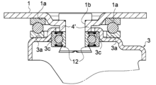
- FIG. 3 is a cross-sectional view of the main parts of a swivel caster.
- FIG. 11 is a cross-sectional view of a main portion with a dust cover added to cover the bearing.
- FIG. FIG. 11 is a cross-sectional view of a main part showing a different embodiment.
- FIG. FIG. FIG. 1 is a cross-sectional view of a main part showing a different embodiment.
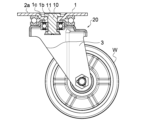
- FIG. 5 shows an example of the swivel caster 20 of the first embodiment as viewed from a vertical section
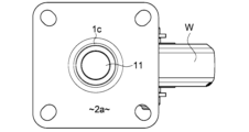
- FIG. 6 shows a plan view
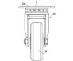
- FIG. 7 shows a front view.
- the enlarged view of the essential part shown in FIG. 1 shows a cross-sectional view taken along the axis of the rotating shaft 10 in the structure around the rotating shaft 10 .
- the rotating shaft 10 has a generally cylindrical shape, and a flange portion 11 is formed on one side in the axial direction.
- the swivel shaft 10 has a bearing mechanism built in between the caster mounting plate 1 and the support yoke 3 that supports the wheel W.
- the bearing mechanism is fixed by the flange portion 11 and the crimped portion 12, which has a large diameter at the lower end, to prevent it from coming loose.
- the caster mounting plate 1 has a generally horizontal flat surface 2a, a mounting hole 1b in the center of the plate that has an inner diameter smaller than the outer diameter of the flange portion 11 of the head of the swivel shaft 10 and through which the shaft portion 10A of the swivel shaft 10 can be inserted, and a recessed portion 1c that extends along the outer periphery of the opening end of the mounting hole 1b and connects to the flat surface 1a.
- the recessed portion 1c is recessed at a position substantially equal to the thickness of the flange portion 11 with respect to the horizontal flat surface 2a on the outer periphery.
- the peripheral portion of the mounting hole 1b forms a horizontal surface for horizontally hanging the upper surface of the flange portion 11 of the rotating shaft 10, and the upper surface of the flange portion 11 hung in the mounting hole 1b is set to be substantially the same plane as the flat surface 2a (see Figure 5).
- the thrust bearing S is arranged on the outer periphery of the radial bearing R above the radial bearing R, and is interposed between the caster mounting plate 1 and the support yoke 3.
- the upper surface of the lower ring S2 of the thrust bearing and the upper end surfaces of the inner ring R1 and outer ring R2 of the radial bearing are arranged in close contact with each other in the height direction so as to be substantially flush with each other.
- the upper surface of the upper wheel S1 of the thrust bearing S abuts against the downward horizontal surface 1a on the underside of the caster mounting plate 1, and the bottom side of the lower wheel S2 of the thrust bearing S abuts against the upward horizontal surface 3a formed in the middle section of the support yoke 3 described below, and the tip of the upward horizontal surface 3a forms a hanging wall 3a' at approximately a right angle.
- a hole 30 on the yoke side which is concentric with and has a larger diameter than the mounting hole 1b, is formed in the upper part of the support yoke 3 at approximately the center position of the upper surface of the support yoke 3.
- the tip of the upward step portion 3b adjacent to the upward horizontal surface 3a forms the rim of the hole 30 on the yoke side
- the upward step portion 3b of the support yoke 3 and the corner portion 3c on the inner surface side are formed into an upward step portion 3L having an L-shaped cross section, and abuts against the upper end of the outer ring R2 of the radial bearing R.
- a spacer portion 4 having a cylindrical cross section and made of a washer which abuts against the rim of the mounting hole 1b, fits snugly around the swivel shaft 10, and hangs down to the same position as the corner 3c on the inner surface of the upward step 3b, and the lower end of the spacer portion 4 abuts against the upper end of the inner ring R1 of the radial bearing R.
- the lower end of the inner ring R1 of the radial bearing R is fixed by a crimped portion 12 at the lower end of the mounting shaft 10 or by a lower spacer portion 5 consisting of a lower washer hooked onto the crimped portion 12 and fixed.
- the lower end of the outer ring R2 of the radial bearing R is open in a hollow position.
- the upward step portion 3b of the support yoke 3 on the rearward movement side of the wheel and the corner portion 3c on the inner surface side form an upward step portion 3L having an L-shaped cross section, and the upward horizontal surface 3a passes through a mid-step portion 3d, and then through a rear horizontal surface portion 3e, and at its tip forms a hanging wall 3e' at an approximately right angle.
- a dust cover 6 made of flexible and elastic synthetic resin or the like is attached below the mounting plate 1 to cover the outer periphery of the thrust bearing S except for the bottom surface.
- the dust cover 6 is attached to overlap the rear surface of the mounting plate 1 and overlaps with the downward horizontal surface 1a to perform the same function as the mounting plate 1, so a description thereof will be omitted.
- the other configurations are the same as those in the first embodiment, and therefore the description will be omitted.
- a hanging wall portion that is formed integrally with the mounting hole 1b and extends downward in a cylindrical shape with the same inner diameter as the hole edge portion is formed as the spacer portion 4'.
- the lower end of the spacer portion 4' which constitutes the hanging wall portion, abuts against the upper end surface of the inner ring R1 of the radial bearing R without any gap, distributing the central load applied to the caster mounting plate 1 to the inner ring R1 side of the radial bearing R.
- the other configurations are the same as those in the first embodiment, and therefore the description thereof will be omitted.
- Example 4 shown in FIG. 4 similar to Example 3 shown in FIG. 3, instead of the separate washer-shaped spacer portion 4, a hanging wall portion that is formed integrally with the mounting hole 1b and extends downward in a cylindrical shape with the same inner diameter as the hole edge portion is formed as the spacer portion 4'.
- the lower end of the spacer portion 4' which constitutes the hanging wall portion, abuts against the upper end surface of the inner ring R1 of the radial bearing R without any gap, distributing the central load applied to the caster mounting plate 1 to the inner ring R1 side of the radial bearing R. Furthermore, the lower end of the inner ring R1 of the radial bearing R is hooked and fixed to a step 12a formed on the crimped portion 12 at the lower end of the mounting shaft 10 without providing a lower spacer portion 5.
- the other configurations are the same as those in the previous embodiment, so the description thereof will be omitted.
- Mounting plate 1a Downward horizontal surface 1b Mounting hole 3 Support yoke 3a Upward horizontal surface 3b Upward step portion 4, 4' Spacer portion 5 Lower step spacer portion 10 Mounting shaft 11 Flange 12 Crimping portion 13 Lower end hook portion 30 Hole on support yoke side S Thrust bearing S1 Upper ring S2 Lower ring R Radial bearing R1 Inner ring R2 Outer ring W Wheel
Landscapes
- Engineering & Computer Science (AREA)
- General Engineering & Computer Science (AREA)
- Mechanical Engineering (AREA)
- Mounting Of Bearings Or Others (AREA)
- Sliding-Contact Bearings (AREA)
Abstract
Priority Applications (2)
| Application Number | Priority Date | Filing Date | Title |
|---|---|---|---|
| KR1020267003144A KR20260071810A (ko) | 2023-06-29 | 2024-06-29 | 선회 캐스터 구조 |
| CN202480056146.XA CN121889276A (zh) | 2023-06-29 | 2024-06-29 | 旋转脚轮结构 |
Applications Claiming Priority (4)
| Application Number | Priority Date | Filing Date | Title |
|---|---|---|---|
| JP2023107611 | 2023-06-29 | ||
| JP2023-107611 | 2023-06-29 | ||
| JP2023-119514 | 2023-07-21 | ||
| JP2023119514A JP7425917B1 (ja) | 2023-06-29 | 2023-07-21 | 旋回キャスタ構造 |
Publications (1)
| Publication Number | Publication Date |
|---|---|
| WO2025005299A1 true WO2025005299A1 (fr) | 2025-01-02 |
Family
ID=89718060
Family Applications (1)
| Application Number | Title | Priority Date | Filing Date |
|---|---|---|---|
| PCT/JP2024/023691 Ceased WO2025005299A1 (fr) | 2023-06-29 | 2024-06-29 | Structure de roulette pivotante |
Country Status (4)
| Country | Link |
|---|---|
| JP (1) | JP7425917B1 (fr) |
| KR (1) | KR20260071810A (fr) |
| CN (1) | CN121889276A (fr) |
| WO (1) | WO2025005299A1 (fr) |
Citations (6)
| Publication number | Priority date | Publication date | Assignee | Title |
|---|---|---|---|---|
| JPS5523939U (fr) * | 1978-08-04 | 1980-02-15 | ||
| JPS58126203A (ja) * | 1982-01-22 | 1983-07-27 | Nanshin Gomme Kogyosho:Kk | キヤスタ−における取付軸の支持構造 |
| JPH11245607A (ja) * | 1998-03-02 | 1999-09-14 | Hammer Caster Kk | キャスター |
| JP2008168835A (ja) * | 2007-01-15 | 2008-07-24 | Masao Kimura | キャスター |
| JP2009154635A (ja) * | 2007-12-26 | 2009-07-16 | Sisiku Addkreis Corp | 緩衝キャスター |
| JP2014111443A (ja) * | 2013-12-24 | 2014-06-19 | Gold Kiyasutaa Kk | キャスターの製造方法 |
Family Cites Families (1)
| Publication number | Priority date | Publication date | Assignee | Title |
|---|---|---|---|---|
| JP2007022254A (ja) | 2005-07-14 | 2007-02-01 | Tomakku:Kk | キャスタ及び台車 |
-
2023
- 2023-07-21 JP JP2023119514A patent/JP7425917B1/ja active Active
-
2024
- 2024-06-29 KR KR1020267003144A patent/KR20260071810A/ko active Pending
- 2024-06-29 WO PCT/JP2024/023691 patent/WO2025005299A1/fr not_active Ceased
- 2024-06-29 CN CN202480056146.XA patent/CN121889276A/zh active Pending
Patent Citations (6)
| Publication number | Priority date | Publication date | Assignee | Title |
|---|---|---|---|---|
| JPS5523939U (fr) * | 1978-08-04 | 1980-02-15 | ||
| JPS58126203A (ja) * | 1982-01-22 | 1983-07-27 | Nanshin Gomme Kogyosho:Kk | キヤスタ−における取付軸の支持構造 |
| JPH11245607A (ja) * | 1998-03-02 | 1999-09-14 | Hammer Caster Kk | キャスター |
| JP2008168835A (ja) * | 2007-01-15 | 2008-07-24 | Masao Kimura | キャスター |
| JP2009154635A (ja) * | 2007-12-26 | 2009-07-16 | Sisiku Addkreis Corp | 緩衝キャスター |
| JP2014111443A (ja) * | 2013-12-24 | 2014-06-19 | Gold Kiyasutaa Kk | キャスターの製造方法 |
Also Published As
| Publication number | Publication date |
|---|---|
| KR20260071810A (ko) | 2026-05-19 |
| CN121889276A (zh) | 2026-04-17 |
| JP2025009598A (ja) | 2025-01-20 |
| JP7425917B1 (ja) | 2024-01-31 |
Similar Documents
| Publication | Publication Date | Title |
|---|---|---|
| CN201659850U (zh) | 车轮轮毂 | |
| JP2017525604A (ja) | ユニバーサル・ホイール・アセンブリおよびスーツケース | |
| JP2002019674A (ja) | 自転車の操舵用ベアリングアセンブリ | |
| TWM534691U (zh) | 腳輪結合裝置 | |
| JP2025009598A (ja) | 旋回キャスタ構造 | |
| JP2595759B2 (ja) | 車両の車体取り付け構造 | |
| JP5992154B2 (ja) | 鞄用キャスター | |
| JP2021031041A (ja) | キャスターおよび運搬台車 | |
| JP5299613B2 (ja) | スラスト軸受 | |
| JPS58126203A (ja) | キヤスタ−における取付軸の支持構造 | |
| JP2003200703A (ja) | キャスター | |
| JP5339241B2 (ja) | キャスター及びその組立方法 | |
| JP2019019927A (ja) | 密封装置 | |
| JP2007096619A (ja) | スピーカ | |
| JP2007022254A (ja) | キャスタ及び台車 | |
| KR102858886B1 (ko) | 역회전이 원활하도록 바퀴를 개선한 캐스터 | |
| JP3961743B2 (ja) | モータ装置 | |
| JP6263157B2 (ja) | ハードディスク駆動装置及びピボットアッシー軸受装置 | |
| JP3067309U (ja) | 静音性キャスタ― | |
| JP3905297B2 (ja) | Ctスキャナの回転体支持用軸受 | |
| JP4124079B2 (ja) | 車両用サスペンション装置のハブ | |
| CN212737614U (zh) | 双圆弧形轨道的万向五金脚轮 | |
| CN213340746U (zh) | 一种接地装置及接地装置的止转机构 | |
| JP3677476B2 (ja) | 車輪取付装置 | |
| KR101020800B1 (ko) | 스핀들 모터 |
Legal Events
| Date | Code | Title | Description |
|---|---|---|---|
| 121 | Ep: the epo has been informed by wipo that ep was designated in this application |
Ref document number: 24832155 Country of ref document: EP Kind code of ref document: A1 |
|
| WWE | Wipo information: entry into national phase |
Ref document number: 202617009086 Country of ref document: IN |
|
| NENP | Non-entry into the national phase |
Ref country code: DE |
|
| WWE | Wipo information: entry into national phase |
Ref document number: 11202508886P Country of ref document: SG |
|
| WWP | Wipo information: published in national office |
Ref document number: 11202508886P Country of ref document: SG |
|
| 122 | Ep: pct application non-entry in european phase |
Ref document number: 24832155 Country of ref document: EP Kind code of ref document: A1 |