WO2025005299A1 - Swivel caster structure - Google Patents
Swivel caster structure Download PDFInfo
- Publication number
- WO2025005299A1 WO2025005299A1 PCT/JP2024/023691 JP2024023691W WO2025005299A1 WO 2025005299 A1 WO2025005299 A1 WO 2025005299A1 JP 2024023691 W JP2024023691 W JP 2024023691W WO 2025005299 A1 WO2025005299 A1 WO 2025005299A1
- Authority
- WO
- WIPO (PCT)
- Prior art keywords
- radial bearing
- mounting
- horizontal surface
- mounting plate
- swivel caster
- Prior art date
- Legal status (The legal status is an assumption and is not a legal conclusion. Google has not performed a legal analysis and makes no representation as to the accuracy of the status listed.)
- Ceased
Links
Images


Classifications
-
- B—PERFORMING OPERATIONS; TRANSPORTING
- B60—VEHICLES IN GENERAL
- B60B—VEHICLE WHEELS; CASTORS; AXLES FOR WHEELS OR CASTORS; INCREASING WHEEL ADHESION
- B60B33/00—Castors in general ; Anti-clogging castors
-
- F—MECHANICAL ENGINEERING; LIGHTING; HEATING; WEAPONS; BLASTING
- F16—ENGINEERING ELEMENTS AND UNITS; GENERAL MEASURES FOR PRODUCING AND MAINTAINING EFFECTIVE FUNCTIONING OF MACHINES OR INSTALLATIONS; THERMAL INSULATION IN GENERAL
- F16C—SHAFTS; FLEXIBLE SHAFTS; ELEMENTS OR CRANKSHAFT MECHANISMS; ROTARY BODIES OTHER THAN GEARING ELEMENTS; BEARINGS
- F16C19/00—Bearings with rolling contact, for exclusively rotary movement
- F16C19/02—Bearings with rolling contact, for exclusively rotary movement with bearing balls essentially of the same size in one or more circular rows
- F16C19/04—Bearings with rolling contact, for exclusively rotary movement with bearing balls essentially of the same size in one or more circular rows for radial load mainly
- F16C19/06—Bearings with rolling contact, for exclusively rotary movement with bearing balls essentially of the same size in one or more circular rows for radial load mainly with a single row or balls
-
- F—MECHANICAL ENGINEERING; LIGHTING; HEATING; WEAPONS; BLASTING
- F16—ENGINEERING ELEMENTS AND UNITS; GENERAL MEASURES FOR PRODUCING AND MAINTAINING EFFECTIVE FUNCTIONING OF MACHINES OR INSTALLATIONS; THERMAL INSULATION IN GENERAL
- F16C—SHAFTS; FLEXIBLE SHAFTS; ELEMENTS OR CRANKSHAFT MECHANISMS; ROTARY BODIES OTHER THAN GEARING ELEMENTS; BEARINGS
- F16C19/00—Bearings with rolling contact, for exclusively rotary movement
- F16C19/02—Bearings with rolling contact, for exclusively rotary movement with bearing balls essentially of the same size in one or more circular rows
- F16C19/10—Bearings with rolling contact, for exclusively rotary movement with bearing balls essentially of the same size in one or more circular rows for axial load mainly
-
- F—MECHANICAL ENGINEERING; LIGHTING; HEATING; WEAPONS; BLASTING
- F16—ENGINEERING ELEMENTS AND UNITS; GENERAL MEASURES FOR PRODUCING AND MAINTAINING EFFECTIVE FUNCTIONING OF MACHINES OR INSTALLATIONS; THERMAL INSULATION IN GENERAL
- F16C—SHAFTS; FLEXIBLE SHAFTS; ELEMENTS OR CRANKSHAFT MECHANISMS; ROTARY BODIES OTHER THAN GEARING ELEMENTS; BEARINGS
- F16C35/00—Rigid support of bearing units; Housings, e.g. caps, covers
- F16C35/04—Rigid support of bearing units; Housings, e.g. caps, covers in the case of ball or roller bearings
- F16C35/06—Mounting or dismounting of ball or roller bearings; Fixing them onto shaft or in housing
- F16C35/07—Fixing them on the shaft or housing with interposition of an element
Definitions
- This invention relates to a swivel caster structure with excellent noise reduction properties that is used as wheels for transport equipment, various transport vehicles, trolleys, etc.
- This invention relates to a swivel caster structure that achieves quieter swivel casters with thrust bearings and radial bearings using a simple configuration.
- this invention provides a bearing comprising a mounting shaft having a flange on an upper end, a mounting plate having a mounting hole through which the mounting shaft is inserted without any gap and through which the flange is hooked, a downward horizontal surface formed on the rear surface of the mounting plate, and a support yoke having a hole on the support yoke side through which the mounting shaft is inserted below the mounting plate and having an upward horizontal surface formed parallel to the downward horizontal surface, the upper wheel of a thrust bearing being supported on the downward horizontal surface, and the lower wheel of a thrust bearing being supported on the upward horizontal surface, an upward step portion that rises on a base end side of the upward horizontal surface of the support yoke, extends in the direction of the pivot axis, and has an L-shaped cross section that extends to a hole on the yoke side; The corner of the upward step hooks the upper part of the outer ring of the radial bearing from above, and the lower part of the outer ring is open.
- each component sandwiched between the flange and the lower end of the rotating shaft can be fixed together without any gaps, so that each component does not swing individually and can efficiently support the load. This also reduces the generation of vibration and noise, ensuring quiet operation during driving.
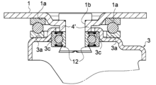
- FIG. 3 is a cross-sectional view of the main parts of a swivel caster.
- FIG. 11 is a cross-sectional view of a main portion with a dust cover added to cover the bearing.
- FIG. FIG. 11 is a cross-sectional view of a main part showing a different embodiment.
- FIG. FIG. FIG. 1 is a cross-sectional view of a main part showing a different embodiment.
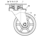
- FIG. 5 shows an example of the swivel caster 20 of the first embodiment as viewed from a vertical section
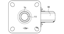
- FIG. 6 shows a plan view
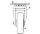
- FIG. 7 shows a front view.
- the enlarged view of the essential part shown in FIG. 1 shows a cross-sectional view taken along the axis of the rotating shaft 10 in the structure around the rotating shaft 10 .
- the rotating shaft 10 has a generally cylindrical shape, and a flange portion 11 is formed on one side in the axial direction.
- the swivel shaft 10 has a bearing mechanism built in between the caster mounting plate 1 and the support yoke 3 that supports the wheel W.
- the bearing mechanism is fixed by the flange portion 11 and the crimped portion 12, which has a large diameter at the lower end, to prevent it from coming loose.
- the caster mounting plate 1 has a generally horizontal flat surface 2a, a mounting hole 1b in the center of the plate that has an inner diameter smaller than the outer diameter of the flange portion 11 of the head of the swivel shaft 10 and through which the shaft portion 10A of the swivel shaft 10 can be inserted, and a recessed portion 1c that extends along the outer periphery of the opening end of the mounting hole 1b and connects to the flat surface 1a.
- the recessed portion 1c is recessed at a position substantially equal to the thickness of the flange portion 11 with respect to the horizontal flat surface 2a on the outer periphery.
- the peripheral portion of the mounting hole 1b forms a horizontal surface for horizontally hanging the upper surface of the flange portion 11 of the rotating shaft 10, and the upper surface of the flange portion 11 hung in the mounting hole 1b is set to be substantially the same plane as the flat surface 2a (see Figure 5).
- the thrust bearing S is arranged on the outer periphery of the radial bearing R above the radial bearing R, and is interposed between the caster mounting plate 1 and the support yoke 3.
- the upper surface of the lower ring S2 of the thrust bearing and the upper end surfaces of the inner ring R1 and outer ring R2 of the radial bearing are arranged in close contact with each other in the height direction so as to be substantially flush with each other.
- the upper surface of the upper wheel S1 of the thrust bearing S abuts against the downward horizontal surface 1a on the underside of the caster mounting plate 1, and the bottom side of the lower wheel S2 of the thrust bearing S abuts against the upward horizontal surface 3a formed in the middle section of the support yoke 3 described below, and the tip of the upward horizontal surface 3a forms a hanging wall 3a' at approximately a right angle.
- a hole 30 on the yoke side which is concentric with and has a larger diameter than the mounting hole 1b, is formed in the upper part of the support yoke 3 at approximately the center position of the upper surface of the support yoke 3.
- the tip of the upward step portion 3b adjacent to the upward horizontal surface 3a forms the rim of the hole 30 on the yoke side
- the upward step portion 3b of the support yoke 3 and the corner portion 3c on the inner surface side are formed into an upward step portion 3L having an L-shaped cross section, and abuts against the upper end of the outer ring R2 of the radial bearing R.
- a spacer portion 4 having a cylindrical cross section and made of a washer which abuts against the rim of the mounting hole 1b, fits snugly around the swivel shaft 10, and hangs down to the same position as the corner 3c on the inner surface of the upward step 3b, and the lower end of the spacer portion 4 abuts against the upper end of the inner ring R1 of the radial bearing R.
- the lower end of the inner ring R1 of the radial bearing R is fixed by a crimped portion 12 at the lower end of the mounting shaft 10 or by a lower spacer portion 5 consisting of a lower washer hooked onto the crimped portion 12 and fixed.
- the lower end of the outer ring R2 of the radial bearing R is open in a hollow position.
- the upward step portion 3b of the support yoke 3 on the rearward movement side of the wheel and the corner portion 3c on the inner surface side form an upward step portion 3L having an L-shaped cross section, and the upward horizontal surface 3a passes through a mid-step portion 3d, and then through a rear horizontal surface portion 3e, and at its tip forms a hanging wall 3e' at an approximately right angle.
- a dust cover 6 made of flexible and elastic synthetic resin or the like is attached below the mounting plate 1 to cover the outer periphery of the thrust bearing S except for the bottom surface.
- the dust cover 6 is attached to overlap the rear surface of the mounting plate 1 and overlaps with the downward horizontal surface 1a to perform the same function as the mounting plate 1, so a description thereof will be omitted.
- the other configurations are the same as those in the first embodiment, and therefore the description will be omitted.
- a hanging wall portion that is formed integrally with the mounting hole 1b and extends downward in a cylindrical shape with the same inner diameter as the hole edge portion is formed as the spacer portion 4'.
- the lower end of the spacer portion 4' which constitutes the hanging wall portion, abuts against the upper end surface of the inner ring R1 of the radial bearing R without any gap, distributing the central load applied to the caster mounting plate 1 to the inner ring R1 side of the radial bearing R.
- the other configurations are the same as those in the first embodiment, and therefore the description thereof will be omitted.
- Example 4 shown in FIG. 4 similar to Example 3 shown in FIG. 3, instead of the separate washer-shaped spacer portion 4, a hanging wall portion that is formed integrally with the mounting hole 1b and extends downward in a cylindrical shape with the same inner diameter as the hole edge portion is formed as the spacer portion 4'.
- the lower end of the spacer portion 4' which constitutes the hanging wall portion, abuts against the upper end surface of the inner ring R1 of the radial bearing R without any gap, distributing the central load applied to the caster mounting plate 1 to the inner ring R1 side of the radial bearing R. Furthermore, the lower end of the inner ring R1 of the radial bearing R is hooked and fixed to a step 12a formed on the crimped portion 12 at the lower end of the mounting shaft 10 without providing a lower spacer portion 5.
- the other configurations are the same as those in the previous embodiment, so the description thereof will be omitted.
- Mounting plate 1a Downward horizontal surface 1b Mounting hole 3 Support yoke 3a Upward horizontal surface 3b Upward step portion 4, 4' Spacer portion 5 Lower step spacer portion 10 Mounting shaft 11 Flange 12 Crimping portion 13 Lower end hook portion 30 Hole on support yoke side S Thrust bearing S1 Upper ring S2 Lower ring R Radial bearing R1 Inner ring R2 Outer ring W Wheel
Landscapes
- Engineering & Computer Science (AREA)
- General Engineering & Computer Science (AREA)
- Mechanical Engineering (AREA)
- Mounting Of Bearings Or Others (AREA)
- Sliding-Contact Bearings (AREA)
Abstract
Description
この発明は、搬送用機器類や各種運搬車、台車類などの車輪として使用される静音効果に優れた旋回キャスタ構造に関する。 This invention relates to a swivel caster structure with excellent noise reduction properties that is used as wheels for transport equipment, various transport vehicles, trolleys, etc.
従来、特許文献1に示す特開2007-22254号のキャスタおよび台車では、同特許文献1の公報の図6から図8に示す第2の実施形態において、旋回軸に、キャスタ取付プレート、スラストベアリング、第1座金、ラジアルベアリング(外輪にヨーク部が固定されている)、第2座金、を順番に挿通して旋回軸と同軸上に配置し、旋回軸の端部をかしめ加工している。
これにより、旋回軸のフランジ部と端部との間に挟み込んだ各部材を固定(挟持)している。
Conventionally, in the caster and bogie disclosed in
This fixes (holds) each member sandwiched between the flange portion and the end portion of the rotating shaft.
しかし、上記構成では、スラストベアリングとラジアルベアリングの間に別体の大径な第1座金でラジアルベアリングの内輪上面を衝合し、ラジアルベアリングのヨークの凹部でラジアルベアリングの外輪下面を支持しているので、前記ベアリングへの荷重が別々に生じて振動時の騒音を防止することができない欠点がある。 However, in the above configuration, a separate large-diameter first washer is placed between the thrust bearing and the radial bearing to abut the top surface of the radial bearing's inner ring, and the recess in the radial bearing's yoke supports the bottom surface of the radial bearing's outer ring. This has the disadvantage that the loads on the bearings are generated separately, making it impossible to prevent noise during vibration.
この発明は、簡単な構成で、スラストベアリングおよびラジアルベアリングを有する旋回キャスタの静音化を実現する旋回キャスタ構造に関する。 This invention relates to a swivel caster structure that achieves quieter swivel casters with thrust bearings and radial bearings using a simple configuration.
前記課題を解決するために、この発明では、上端にフランジを有する取付軸と、該取付軸が隙間無く貫挿されフランジが掛止められる取付穴を有する取付プレートと、該取付プレートの裏面に形成された下向き水平面と、前記取付プレートの下方で前記取付軸を貫挿する支持ヨーク側の孔を有すると共に前記下向き水平面と平行に対峙する上向き水平面が形成された支持ヨークとからなっており、前記下向き水平面にスラストベアリングの上輪が支持され、上向き水平面にスラストベアリングの下輪が支持されており、
前記支持ヨークの上向き水平面の基端側で立ち上がり、前記旋回軸方向に延びてヨーク側の孔まで延びる断面L字状となる上向き段部と、
該上向き段部の角部がラジアルベアリングの外輪の上部を上から掛け止めてなり外輪の下方は開放されてなり、
前記取付穴から上向き段部の間で旋回軸に沿って垂下し、下端がラジアルベアリングの内輪の上端と衝合するスペーサー部とからなって、
ラジアルベアリングの内輪の下端が、前記取付軸の下端側に固定されてなることを特徴とする。
In order to solve the above problems, this invention provides a bearing comprising a mounting shaft having a flange on an upper end, a mounting plate having a mounting hole through which the mounting shaft is inserted without any gap and through which the flange is hooked, a downward horizontal surface formed on the rear surface of the mounting plate, and a support yoke having a hole on the support yoke side through which the mounting shaft is inserted below the mounting plate and having an upward horizontal surface formed parallel to the downward horizontal surface, the upper wheel of a thrust bearing being supported on the downward horizontal surface, and the lower wheel of a thrust bearing being supported on the upward horizontal surface,
an upward step portion that rises on a base end side of the upward horizontal surface of the support yoke, extends in the direction of the pivot axis, and has an L-shaped cross section that extends to a hole on the yoke side;
The corner of the upward step hooks the upper part of the outer ring of the radial bearing from above, and the lower part of the outer ring is open.
a spacer portion that extends downward along the swivel shaft between the mounting hole and the upward step portion, and whose lower end abuts against an upper end of the inner ring of the radial bearing;
The lower end of the inner ring of the radial bearing is fixed to the lower end side of the mounting shaft.
これにより、旋回軸のフランジ部と下端部との間に挟み込んだ各部材を隙間無く一体的に固定することができるので、各部材が個別に揺動することがなく、効率的に荷重を受けることができると共に、振動や騒音の発生を抑えて、走行時の静音を確実に行うことができる。 As a result, each component sandwiched between the flange and the lower end of the rotating shaft can be fixed together without any gaps, so that each component does not swing individually and can efficiently support the load. This also reduces the generation of vibration and noise, ensuring quiet operation during driving.
以下に、この発明の好適実施例について図面を参照しながら説明する。 Below, a preferred embodiment of the invention will be described with reference to the drawings.
実施例1の旋回キャスタ20は、図5に縦断面から見た一例を示し、図6が平面図、図7が正面図を示している。
図1に示す要部拡大図は、旋回軸10の周辺の構造で旋回軸10の軸線に沿った断面図を示している。
前記旋回軸10は、略円柱状の形状を有しており、軸線方向の一方の側にフランジ部11が形成されている。
FIG. 5 shows an example of the
The enlarged view of the essential part shown in FIG. 1 shows a cross-sectional view taken along the axis of the rotating
The rotating
旋回軸10は、キャスタ取付プレート1と車輪Wを軸支する支持ヨーク3との間に、前記フランジ部11と、下端側で大径となる抜け止め用のかしめ部12によって固定されるベアリング機構が内蔵されている。
The
即ち、前記キャスタ取付プレート1は、略水平な扁平面2aと、その略中央に旋回軸10の頭部のフランジ部11の外径よりも小さな内径を有するとともに旋回軸10の軸部10Aを挿通可能な取付穴1bと、該取付穴1bの開口端外周に沿って延び扁平面1aに連なる窪み部1cが形成されている。
In other words, the
前記窪み部1cは、周囲の外方の水平な扁平面2aに対して、フランジ部11の厚みとがほぼ同じ位置となるように窪んでいる。
また、前記取付穴1bの周縁部は旋回軸10のフランジ部11の上面を水平に掛止めるための水平面となっており、取付穴1bに掛け止められた前記フランジ部11の上面は前記扁平面2aとほぼ同一な平面状となるように設定されている(図5参照)。
The recessed
In addition, the peripheral portion of the
次に、スラストベアリングSは、ラジアルベアリングRの上段でラジアルベアリングRの外周側に配置されており、キャスタ取付プレート1と支持ヨーク3との間に介設されている。
図示例では、スラストベアリングの下輪S2の上面とラジアルベアリングの内輪R1、外輪R2の上端面とがほぼ同一面となるように高さ方向に密着して配置されている。
Next, the thrust bearing S is arranged on the outer periphery of the radial bearing R above the radial bearing R, and is interposed between the
In the illustrated example, the upper surface of the lower ring S2 of the thrust bearing and the upper end surfaces of the inner ring R1 and outer ring R2 of the radial bearing are arranged in close contact with each other in the height direction so as to be substantially flush with each other.
そして、スラストベアリングSの上輪S1は、その上面が、キャスタ取付プレート1の裏面の下向き水平面1aと衝合しており、スラストベアリングSの下輪S2の底面側が、支持ヨーク3の後述の中段に形成された上向き水平面3aに衝合しており、上向き水平面3aの先端で略直角に垂下壁3a’となっている。
また、支持ヨーク3の上部には、前記取付穴1bより同心大径なヨーク側の孔30が穿設されており、支持ヨーク3の上面の略中間位置に穿設されている。
The upper surface of the upper wheel S1 of the thrust bearing S abuts against the downward
Further, a
また、前記上向き水平面3aに隣接する上向き段部3bの先端でヨーク側の孔30の口縁部となっており、支持ヨーク3の上向き段部3bと内面側の角部3cとが断面L字状となる上向き段部3Lに形成されており、ラジアルベアリングRの外輪R2の上端と衝合している。
一方、前記取付穴1bの真下には、該取付穴1bの口縁部と衝合し旋回軸10に隙間無く嵌合して前記上向き段部3bの内面側の角部3cと同一位置まで垂下するワッシャからなる断面円筒状のスペーサー部4が取り付けられており、該スペーサー部4の下端がラジアルベアリングRの内輪R1の上端と衝合している。
In addition, the tip of the
On the other hand, directly below the
そして前記ラジアルベアリングRの内輪R1の下端は、取付軸10の下端のかしめ部12または、かしめ部12に掛け止められて固定される下段ワッシャからなる下段スペーサー部5によって固定されている。
一方、ラジアルベアリングRの外輪R2は、下端が中空位置に開放されている。
上記構成からなっているので、スラストベアリングSはその上輪S1、下輪S2のそれぞれの外向きの側方が開放されており、またラジアルベアリングRの外輪R2の下端が開放された構成からなっているので、簡単な構成で静音効果を奏することができる。
なお、車輪後進側の支持ヨーク3の上向き段部3bと内面側の角部3cとが断面L字状となる上向き段部3Lとなり、上向き水平面3aから中途段部3dを介して後方水平面部3eを介してその先端で略直角に垂下壁3e’となっている。
The lower end of the inner ring R1 of the radial bearing R is fixed by a crimped
On the other hand, the lower end of the outer ring R2 of the radial bearing R is open in a hollow position.
As a result of the above-mentioned configuration, the thrust bearing S has its upper ring S1 and lower ring S2 each having an open outward side, and the lower end of the outer ring R2 of the radial bearing R is also open, so that a noise reduction effect can be achieved with a simple configuration.
In addition, the
図2示す実施例2では、取付プレート1の下方でスラストベアリングSの底面を除く外周を覆う柔軟性や弾性を有する合成樹脂などからなるダストカバー6が装着されている。
ダストカバー6は、取付プレート1の裏面に重なって取り付けられており、下向き水平面1aと重なって取付プレート1と同じ機能を発揮するので、その説明を省略する。
その他の構成は前記実施例1と同様であるので、説明を省略する。
In the second embodiment shown in FIG. 2, a
The
The other configurations are the same as those in the first embodiment, and therefore the description will be omitted.
図3に示す実施例3では、前記別体のワッシャー状のスペーサー部4に替えて、前記取付穴1bと一体に形成されて、孔縁部と同一内径で下方に筒状に延びる垂下壁部がスペーサー部4’として形成されている。
そして、前記垂下壁部となるスペーサー部4’の下端はラジアルベアリングRの内輪R1の上端面と隙間無く衝合しており、キャスタ取付プレート1にかかる中心側の荷重をラジアルベアリングRの内輪R1側に分散している。
その他の構成は、前記実施例1と同様であるので、その説明を省略する。
In the third embodiment shown in FIG. 3, instead of the separate washer-
The lower end of the spacer portion 4', which constitutes the hanging wall portion, abuts against the upper end surface of the inner ring R1 of the radial bearing R without any gap, distributing the central load applied to the
The other configurations are the same as those in the first embodiment, and therefore the description thereof will be omitted.
図4に示す実施例4では、図3に示す実施例3と同様に、前記別体のワッシャー状のスペーサー部4に替えて、前記取付穴1bと一体に形成されて、孔縁部と同一内径で下方に筒状に延びる垂下壁部がスペーサー部4’として形成されている。
In Example 4 shown in FIG. 4, similar to Example 3 shown in FIG. 3, instead of the separate washer-
そして、前記垂下壁部となるスペーサー部4’の下端はラジアルベアリングRの内輪R1の上端面と隙間無く衝合しており、キャスタ取付プレート1にかかる中心側の荷重をラジアルベアリングRの内輪R1側に分散している。
また、ラジアルベアリングRの内輪R1の下端は、下段スペーサー部5を設けずに取付軸10の下端のかしめ部12に形成された段部12aに掛け止められて固定されている。
その他の構成は前記実施例と同様であるので、その説明を省略する。
The lower end of the spacer portion 4', which constitutes the hanging wall portion, abuts against the upper end surface of the inner ring R1 of the radial bearing R without any gap, distributing the central load applied to the
Furthermore, the lower end of the inner ring R1 of the radial bearing R is hooked and fixed to a step 12a formed on the crimped
The other configurations are the same as those in the previous embodiment, so the description thereof will be omitted.
1 取付プレート
1a 下向き水平面
1b 取付穴
3 支持ヨーク
3a 上向き水平面
3b 上向き段部
4、4’ スペーサー部
5 下段スペーサー部
10 取付軸
11 フランジ
12 かしめ部
13 下端掛止部
30 支持ヨーク側の孔
S スラストベアリング
S1 上輪
S2 下輪
R ラジアルベアリング
R1 内輪
R2 外輪
W 車輪
1
Claims (6)
該取付プレートの裏面に形成された下向き水平面と、前記取付プレートの下方で前記取付軸を貫挿する支持ヨーク側の孔を有すると共に前記下向き水平面と平行に対峙する上向き水平面が形成された支持ヨークとからなっており、前記下向き水平面にスラストベアリングの上輪が支持され、上向き水平面にスラストベアリングの下輪が支持されており、
前記支持ヨークの上向き水平面の基端側で立ち上がり、旋回軸方向に延びてヨーク側の孔まで延びる断面L字状となる上向き段部と、
該上向き段部の角部がラジアルベアリングの外輪の上部を上から掛け止めてなり外輪の下方は開放されてなり、
前記取付穴から上向き段部の間で旋回軸に沿って垂下し、下端がラジアルベアリングの内輪の上端と衝合するスペーサー部とからなって、
ラジアルベアリングの内輪の下端が、前記取付軸の下端側に固定されており、
取付プレートと支持ヨークとで上下に挟まれた前記スラストベアリングの上輪および下輪のそれぞれの外向きの側方が掛止めされることなく開放されており、
またラジアルベアリングの外輪の下端が掛止めされることなく開放された構成からなっていること特徴とする旋回キャスタ構造。 a mounting shaft having a flange at an upper end, and a mounting plate having a mounting hole through which the mounting shaft is inserted without any gap and through which the flange is hooked;
The mounting plate has a downward horizontal surface formed on its rear surface, and a support yoke having a hole on the support yoke side through which the mounting shaft is inserted below the mounting plate and an upward horizontal surface formed parallel to the downward horizontal surface, an upper wheel of a thrust bearing is supported on the downward horizontal surface, and a lower wheel of a thrust bearing is supported on the upward horizontal surface,
an upward step portion that rises on a base end side of the upward horizontal surface of the support yoke, extends in the direction of the pivot axis, and has an L-shaped cross section that extends to a hole on the yoke side;
The corner of the upward step hooks the upper part of the outer ring of the radial bearing from above, and the lower part of the outer ring is open.
a spacer portion that extends downward along the swivel shaft between the mounting hole and the upward step portion, and whose lower end abuts against an upper end of the inner ring of the radial bearing;
The lower end of the inner ring of the radial bearing is fixed to the lower end side of the mounting shaft,
The upper and lower wheels of the thrust bearing are sandwiched between the mounting plate and the support yoke from above and below, and the outward sides of the upper and lower wheels are open and not latched,
The swivel caster structure is also characterized in that the lower end of the outer ring of the radial bearing is not latched but is open.
Priority Applications (2)
| Application Number | Priority Date | Filing Date | Title |
|---|---|---|---|
| KR1020267003144A KR20260071810A (en) | 2023-06-29 | 2024-06-29 | Slewing caster structure |
| CN202480056146.XA CN121889276A (en) | 2023-06-29 | 2024-06-29 | Structure of swivel caster |
Applications Claiming Priority (4)
| Application Number | Priority Date | Filing Date | Title |
|---|---|---|---|
| JP2023107611 | 2023-06-29 | ||
| JP2023-107611 | 2023-06-29 | ||
| JP2023-119514 | 2023-07-21 | ||
| JP2023119514A JP7425917B1 (en) | 2023-06-29 | 2023-07-21 | Swivel caster structure |
Publications (1)
| Publication Number | Publication Date |
|---|---|
| WO2025005299A1 true WO2025005299A1 (en) | 2025-01-02 |
Family
ID=89718060
Family Applications (1)
| Application Number | Title | Priority Date | Filing Date |
|---|---|---|---|
| PCT/JP2024/023691 Ceased WO2025005299A1 (en) | 2023-06-29 | 2024-06-29 | Swivel caster structure |
Country Status (4)
| Country | Link |
|---|---|
| JP (1) | JP7425917B1 (en) |
| KR (1) | KR20260071810A (en) |
| CN (1) | CN121889276A (en) |
| WO (1) | WO2025005299A1 (en) |
Citations (6)
| Publication number | Priority date | Publication date | Assignee | Title |
|---|---|---|---|---|
| JPS5523939U (en) * | 1978-08-04 | 1980-02-15 | ||
| JPS58126203A (en) * | 1982-01-22 | 1983-07-27 | Nanshin Gomme Kogyosho:Kk | Fitting shaft support structure of caster |
| JPH11245607A (en) * | 1998-03-02 | 1999-09-14 | Hammer Caster Kk | caster |
| JP2008168835A (en) * | 2007-01-15 | 2008-07-24 | Masao Kimura | Caster |
| JP2009154635A (en) * | 2007-12-26 | 2009-07-16 | Sisiku Addkreis Corp | Buffer caster |
| JP2014111443A (en) * | 2013-12-24 | 2014-06-19 | Gold Kiyasutaa Kk | Method of producing caster |
Family Cites Families (1)
| Publication number | Priority date | Publication date | Assignee | Title |
|---|---|---|---|---|
| JP2007022254A (en) | 2005-07-14 | 2007-02-01 | Tomakku:Kk | Caster and truck |
-
2023
- 2023-07-21 JP JP2023119514A patent/JP7425917B1/en active Active
-
2024
- 2024-06-29 KR KR1020267003144A patent/KR20260071810A/en active Pending
- 2024-06-29 WO PCT/JP2024/023691 patent/WO2025005299A1/en not_active Ceased
- 2024-06-29 CN CN202480056146.XA patent/CN121889276A/en active Pending
Patent Citations (6)
| Publication number | Priority date | Publication date | Assignee | Title |
|---|---|---|---|---|
| JPS5523939U (en) * | 1978-08-04 | 1980-02-15 | ||
| JPS58126203A (en) * | 1982-01-22 | 1983-07-27 | Nanshin Gomme Kogyosho:Kk | Fitting shaft support structure of caster |
| JPH11245607A (en) * | 1998-03-02 | 1999-09-14 | Hammer Caster Kk | caster |
| JP2008168835A (en) * | 2007-01-15 | 2008-07-24 | Masao Kimura | Caster |
| JP2009154635A (en) * | 2007-12-26 | 2009-07-16 | Sisiku Addkreis Corp | Buffer caster |
| JP2014111443A (en) * | 2013-12-24 | 2014-06-19 | Gold Kiyasutaa Kk | Method of producing caster |
Also Published As
| Publication number | Publication date |
|---|---|
| KR20260071810A (en) | 2026-05-19 |
| CN121889276A (en) | 2026-04-17 |
| JP2025009598A (en) | 2025-01-20 |
| JP7425917B1 (en) | 2024-01-31 |
Similar Documents
| Publication | Publication Date | Title |
|---|---|---|
| CN201659850U (en) | wheel hub | |
| JP2017525604A (en) | Universal wheel assembly and suitcase | |
| JP2002019674A (en) | Bicycle steering bearing assembly | |
| TWM534691U (en) | Caster engagement device | |
| JP2025009598A (en) | Swivel caster structure | |
| JP2595759B2 (en) | Vehicle mounting structure | |
| JP5992154B2 (en) | Casters for firewood | |
| JP2021031041A (en) | Caster and transport dolly | |
| JP5299613B2 (en) | Thrust bearing | |
| JPS58126203A (en) | Fitting shaft support structure of caster | |
| JP2003200703A (en) | caster | |
| JP5339241B2 (en) | Caster and its assembly method | |
| JP2019019927A (en) | Sealing device | |
| JP2007096619A (en) | Speaker | |
| JP2007022254A (en) | Caster and truck | |
| KR102858886B1 (en) | Caster with improved wheels for smooth reverse rotation | |
| JP3961743B2 (en) | Motor equipment | |
| JP6263157B2 (en) | Hard disk drive device and pivot assembly bearing device | |
| JP3067309U (en) | Silent caster | |
| JP3905297B2 (en) | Bearing for supporting the rotating body of CT scanner | |
| JP4124079B2 (en) | Hub for vehicle suspension system | |
| CN212737614U (en) | Universal hardware trundle with double arc-shaped rails | |
| CN213340746U (en) | A grounding device and the anti-rotation mechanism of the grounding device | |
| JP3677476B2 (en) | Wheel mounting device | |
| KR101020800B1 (en) | Spindle motor |
Legal Events
| Date | Code | Title | Description |
|---|---|---|---|
| 121 | Ep: the epo has been informed by wipo that ep was designated in this application |
Ref document number: 24832155 Country of ref document: EP Kind code of ref document: A1 |
|
| WWE | Wipo information: entry into national phase |
Ref document number: 202617009086 Country of ref document: IN |
|
| NENP | Non-entry into the national phase |
Ref country code: DE |
|
| WWE | Wipo information: entry into national phase |
Ref document number: 11202508886P Country of ref document: SG |
|
| WWP | Wipo information: published in national office |
Ref document number: 11202508886P Country of ref document: SG |
|
| 122 | Ep: pct application non-entry in european phase |
Ref document number: 24832155 Country of ref document: EP Kind code of ref document: A1 |