WO2025005152A1 - コンパクト容器 - Google Patents
コンパクト容器 Download PDFInfo
- Publication number
- WO2025005152A1 WO2025005152A1 PCT/JP2024/023244 JP2024023244W WO2025005152A1 WO 2025005152 A1 WO2025005152 A1 WO 2025005152A1 JP 2024023244 W JP2024023244 W JP 2024023244W WO 2025005152 A1 WO2025005152 A1 WO 2025005152A1
- Authority
- WO
- WIPO (PCT)
- Prior art keywords
- pressing portion
- hook piece
- leaf spring
- container body
- container
- Prior art date
- Legal status (The legal status is an assumption and is not a legal conclusion. Google has not performed a legal analysis and makes no representation as to the accuracy of the status listed.)
- Ceased
Links
Images






Classifications
-
- A—HUMAN NECESSITIES
- A45—HAND OR TRAVELLING ARTICLES
- A45D—HAIRDRESSING OR SHAVING EQUIPMENT; EQUIPMENT FOR COSMETICS OR COSMETIC TREATMENTS, e.g. FOR MANICURING OR PEDICURING
- A45D33/00—Containers or accessories specially adapted for handling powdery toiletry or cosmetic substances
- A45D33/006—Vanity boxes or cases, compacts, i.e. containing a powder receptacle and a puff or applicator
-
- A—HUMAN NECESSITIES
- A45—HAND OR TRAVELLING ARTICLES
- A45D—HAIRDRESSING OR SHAVING EQUIPMENT; EQUIPMENT FOR COSMETICS OR COSMETIC TREATMENTS, e.g. FOR MANICURING OR PEDICURING
- A45D33/00—Containers or accessories specially adapted for handling powdery toiletry or cosmetic substances
-
- A—HUMAN NECESSITIES
- A45—HAND OR TRAVELLING ARTICLES
- A45D—HAIRDRESSING OR SHAVING EQUIPMENT; EQUIPMENT FOR COSMETICS OR COSMETIC TREATMENTS, e.g. FOR MANICURING OR PEDICURING
- A45D40/00—Casings or accessories specially adapted for storing or handling solid or pasty toiletry or cosmetic substances, e.g. shaving soaps or lipsticks
- A45D40/22—Casings characterised by a hinged cover
-
- A—HUMAN NECESSITIES
- A45—HAND OR TRAVELLING ARTICLES
- A45D—HAIRDRESSING OR SHAVING EQUIPMENT; EQUIPMENT FOR COSMETICS OR COSMETIC TREATMENTS, e.g. FOR MANICURING OR PEDICURING
- A45D40/00—Casings or accessories specially adapted for storing or handling solid or pasty toiletry or cosmetic substances, e.g. shaving soaps or lipsticks
- A45D40/22—Casings characterised by a hinged cover
- A45D2040/225—Casings characterised by a hinged cover characterised by the opening or closing movement of the lid
Definitions
- the present invention relates to a compact container.
- a conventional compact container in which a hook piece (operating member) fitted to the container body can be pushed in against the elasticity of the leaf spring of the hook piece to release the hook (engaging protrusion) on the hook piece from the lid, thereby making it possible to open the lid (see, for example, Patent Document 1).
- the object of the present invention is to provide a compact container that can easily release the hook on the hook piece from the lid, regardless of the position of the hook piece.
- the compact container of the present invention comprises a container body, a storage member housed in the container body, a lid, and a hook piece disposed on the container body and equipped with a hook that can be hooked onto the lid, and the hook and the lid are released from their engagement by pushing the hook piece into the container body against the elastic force of a leaf spring provided on the hook piece, and the container body and the storage member are each provided with a pressing portion that cooperates with each other to pinch and press the leaf spring in the direction in which the hook piece is pushed in.
- the pressing portion of the pressing part may be a curved surface that makes line contact with the surface of the leaf spring.
- the pressing portion of the pressing part may be a surface that comes into surface contact with the surface of the leaf spring.
- the pressing portion of the pressing part may be a surface on which a plurality of protrusions are provided.
- the housing member may be a frame member.
- the present invention provides a compact container that can easily release the hook on the hook piece from the lid, regardless of the position of the hook piece when pressed into place.
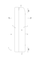
- FIG. 1 is a front view that diagrammatically illustrates a compact case according to a first embodiment of the present invention.
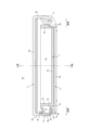
- FIG. 2 is a schematic side view of the compact container of FIG. 1.
- FIG. 2 is a schematic plan view of the compact case of FIG. 1;
- 4 is a cross-sectional view showing the compact case of FIG. 3 along the X1-X1 cross section.
- 4 is a cross-sectional view showing the compact case of FIG. 3 along the X2-X2 cross section.
- 4 is a cross-sectional view showing the compact case of FIG. 3 along the X3-X3 section.
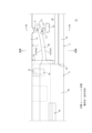
- 2 is a plan view showing an enlarged schematic diagram of the relationship between the case body, the frame member, and the hook piece of the compact case of FIG. 1.
- FIG. 8 is a cross-sectional view showing the relationship in FIG. 7 along the X4-X4 cross section.
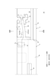
- This is a plan view showing an enlarged schematic diagram of the relationship between the case body, frame member, and hook piece of a compact case according to a second embodiment of the present invention.
- This is a plan view showing an enlarged schematic diagram of the relationship between the container body, frame member, and hook piece of a compact container according to a third embodiment of the present invention.
- FIG. 1 shows a schematic diagram of a compact container 1A according to a first embodiment of the present invention.
- FIG. 2 shows a schematic diagram of a side view of the compact container 1A.
- FIG. 3 shows a schematic diagram of the internal structure of the compact container 1A as seen through the lid 3.
- front side refers to the side where the hook piece 4, described below, is located.
- rear side refers to the side where the pin 5, described below, is located.
- upper side refers to the side where the lid body 3, described below, is located.
- lower side refers to the side where the container body 2, described below, is located.
- right side and “left side” are based on the “front side,” and “left-right direction” is also referred to as "width direction.”
- compact container 1A comprises container body 2, lid body 3, and hook piece 4 arranged on container body 2.
- compact container 1A releases the engagement between lid body 3 and hook piece 4 by pushing hook piece 4 into container body 2.
- hook piece 4 is exposed to the outside of container body 2 through notch 2e formed in front wall 2a of container body 2.
- lid body 3 can be opened and closed around rear wall 2b of container body 2, as shown by the arrow in FIG. 2.
- the lid body 3 is rotatably attached to the rear wall 2b of the container body 2 via a pin 5.
- the compact container 1A according to this embodiment is provided with two pins 5 spaced apart in the width direction. This allows the lid body 3 to be opened and closed relative to the container body 2, with the pins 5 as the base point.
- the compact container 1A according to this embodiment is provided with a torsion spring 6.
- the torsion spring 6 is attached to a pin 5.
- the two ends of the torsion spring 6 each come into contact with either the container body 2 or the lid body 3, generating a biasing force in a direction in which the lid body 3 opens relative to the container body 2.
- the lid body 3 can automatically open relative to the container body 2 when the hook between the lid body 3 and the hook piece 4 is released.
- the side of the compact container 1A is shown in half cross section.
- the torsion spring 6 is attached to only one of the two pins 5. However, the torsion spring 6 can be attached to each of the two pins 5. Also, the torsion spring 6 can be omitted.
- the compact container 1A includes a storage member 7 housed in the container body 2.
- the storage member 7 is a frame member.
- the storage member 7 is housed in a recess 2n formed in the container body 2.
- the container body 2 includes a front wall 2a, a rear wall 2b spaced apart from the front wall 2a in the front-rear direction, and two side walls 2c spaced apart in the width direction.
- the two side walls 2c are connected to the widthwise ends of the front wall 2a and the rear wall 2b, respectively.
- the container body 2 includes a bottom wall 2d (see, for example, FIG. 4) that is connected to each of the front wall 2a, the rear wall 2b, and the two side walls 2c.
- the recess 2n in which the storage member 7 is housed is defined inside these walls.
- the storage member 7 has a front wall 7a, a rear wall 7b spaced apart from the front wall 7a in the front-rear direction, and two side walls 7c spaced apart in the width direction.
- the two side walls 7c are connected to the widthwise ends of the front wall 7a and the rear wall 7b, respectively.
- the storage member 7 has a bottom wall 7d (see FIG. 5, for example) that is connected to each of the front wall 7a, the rear wall 7b, and the two side walls 7c.
- the storage member 7 also has a recess 7n defined inside these walls.
- the recess 7n can store, for example, a tray or makeup tools.
- the cover 3 comprises a front wall 3a, a rear wall 3b spaced apart from the front wall 3a in the front-to-rear direction, and two side walls 3c spaced apart in the width direction (only one of the two side walls 3c is shown in FIG. 5).
- the two side walls 3c are connected to the widthwise ends of the front wall 3a and the rear wall 3b, respectively.
- the cover 3 comprises a top wall 3d that is connected to each of the front wall 3a, the rear wall 3b, and the two side walls 3c.
- a mirror M is attached to the inner surface of the top wall 3d.
- the hook piece 4 has a hook 4f that can be hooked to the lid body 3.
- the hook piece 4 has a pressing portion 4a.
- the pressing portion 4a is a portion that a user directly touches with his/her finger to push the hook piece 4 into the inside of the container body 2.
- the hook 4f is an upper hook that is integrally provided on the upper surface of the pressing portion 4a.
- the hook 4f protrudes toward the front side.
- the hook 4f can be hooked to a lower protrusion 3f formed on the rear surface of the front wall 3a of the lid body 3 as shown in FIG. 4.
- the lower protrusion 3f protrudes toward the rear side.
- the hook 4f of the hook piece 4 hooks onto the lower protrusion 3f of the lid body 3, thereby preventing the lid body 3 from opening relative to the container body 2.
- FIG. 7 the relationship between the container body 2, the housing member 7, and the hook piece 4 of the compact container 1A is shown enlarged and schematic. However, in Fig. 7, only one half of the compact container 1A is shown enlarged.
- the hook piece 4 is provided with a leaf spring 4b.
- the hook piece 4 is provided with two leaf springs 4b spaced apart in the width direction (FIG. 7 shows only one of the two leaf springs 4b).
- the two leaf springs 4b are integrally provided on one side surface in the width direction of the pressing portion 4a (the left side surface in the width direction in FIG. 7), for example, as shown in FIG. 7.
- the leaf springs 4b can be placed at any position on the pressing portion 4a as long as they can generate a repulsive force (biasing force) on the front side when the hook piece 4 is pushed rearward.
- the hook 4f of the hook piece 4 and the lower protrusion 3f of the lid 3 are released by pushing the hook piece 4 into the container body 2 against the elastic force of the leaf spring 4b provided on the hook piece 4.
- the hook piece 4 is slidably disposed on the upper surface of a bottom plate 7e provided on the housing member 7.
- the bottom plate 7e is integrally provided on the front wall 7a of the housing member 7.
- the bottom plate 7e extends from the outer surface of the front wall 7a toward the front side.
- a guide portion 7g is formed on the upper surface of the bottom plate 7e.
- the guide portion 7g extends in the front-rear direction.
- the guide portion 7g is a through hole.
- a guide protrusion 4c provided on the hook piece 4 is inserted into the guide portion 7g.
- the guide protrusion 4c is integrally provided on the lower surface of the pressing portion 4a. This allows the hook piece 4 to slide in the front-rear direction on the bottom plate 7e along the guide portion 7g.
- the guide portion 7g can be a guide groove.
- the compact container 1A is provided with a pressing portion (21, 71) on each of the container body 2 and the housing member 7 housed in the container body 2, which cooperate with each other to pinch and press the leaf spring 4b in the pushing direction of the hook piece 4.
- the pushing direction of the hook piece 4 is the front-rear direction.
- the pressing portion provided on the container body 2 is a front pressing portion 21 that presses the leaf spring 4b of the hook piece 4 from the front side.
- the front pressing portion 21 is provided on the bottom wall 2d of the container body 2.
- the front pressing portion 21 extends in the front-rear direction.
- the rear end of the front pressing portion 21 constitutes the pressing portion F1 of the front pressing portion 21.
- the widthwise extending portion 22 is connected to the front end of the front pressing portion 21.
- the widthwise extending portion 22 extends from the front end of the front pressing portion 21 to the outside in the width direction (to the left in the width direction in FIG. 7).
- the front pressing portion 21 protrudes upward from the upper surface of the bottom wall 2d together with the widthwise extending portion 22.
- the pressing portion provided on the storage member 7 is a rear pressing portion 71 that presses the leaf spring 4b of the hook piece 4 from the rear side.
- the rear pressing portion 71 is provided on the front wall 7a of the storage member 7.
- the rear pressing portion 71 protrudes forward from the front surface of the front wall 7a of the storage member 7.
- the front end of the rear pressing portion 71 constitutes the pressing portion F2 of the rear pressing portion 71.
- the leaf spring 4b of the hook piece 4 is arranged so that the width direction of the leaf spring 4b (the short side direction of the leaf spring 4b) is parallel to the vertical direction.
- the leaf spring 4b of the hook piece 4 is arranged so that the surface F4 of the leaf spring 4b extends in the vertical direction.
- the pressing portion F1 of the front pressing portion 21 provided on the container body 2 contacts the front surface F41 of the leaf spring 4b in the width direction (up-down direction) of the leaf spring 4b, as shown in Figure 8.
- the pressing portion F2 of the rear pressing portion 71 provided on the storage member 7 contacts the rear surface F42 of the leaf spring 4b in the width direction (up-down direction) of the leaf spring 4b, as shown in Figure 8. Therefore, the front pressing portion 21 and the rear pressing portion 71 cooperate with each other to press down the leaf spring 4b so as to sandwich it in the pushing direction (front-back direction) of the hook piece 4.
- the two leaf springs 4b provided on the hook piece 4 are each pressed down by the front pressing portion 21 provided on the container body 2 and the rear pressing portion 71 provided on the housing member 7 so as to be sandwiched in the direction in which the hook piece 4 is pushed in.
- the upper portion of the hook piece 4 is less likely to tilt forward. Therefore, according to the compact container 1A, unlike conventional compact containers, when the lower portion of the push piece is pushed in, the push piece does not tilt forward, thereby increasing the amount of engagement between the hook and the lid. Therefore, according to the compact container 1A, the engagement between the hook 4f provided on the hook piece 4 and the lid 3 can be easily released, regardless of the position of the push in relative to the hook piece 4.
- the pressing portions (F1, F2) of the container body 2 and the housing member 7 are curved surfaces that make line contact with the surface F4 of the leaf spring 4b.
- the pressing portion F1 of the front pressing portion 21 is a curved surface with a radius of curvature r1 in a plan view.
- the pressing portion F1 of the front pressing portion 21 allows the front pressing portion 21 to make line contact in the vertical direction with the front surface F41 of the leaf spring 4b.
- the pressing portion F2 of the rear pressing portion 71 is a curved surface with a radius of curvature r2 in a plan view.
- the pressing portion F2 of the rear pressing portion 71 allows the rear pressing portion 71 to make line contact in the vertical direction with the rear surface F42 of the leaf spring 4b.
- the pressing portions (F1, F2) of the container body 2 and the housing member 7 are curved surfaces that make line contact with the surface F4 of the leaf spring 4b, as in the case of the compact container 1A, the surface F4 of the leaf spring 4b can be pressed by line contact in the vertical direction.
- the curved surfaces of the pressing portions (F1, F2) are configured as curved surfaces with a radius of curvature, as in this embodiment, stress concentration on the surface F4 of the leaf spring 4b can be reduced.
- FIG. 9 shows, in a similar manner to FIG. 7, a schematic enlarged view of the relationship between the container body 2, the housing member 7, and the hook piece 4 in a compact container 1B, which is a second embodiment of the present invention. Note that in compact container 1B, parts that are substantially the same as those in compact container 1A are given the same reference numerals.
- the pressing portions (F1, F2) of the container body 2 and the housing member 7 are surfaces that come into surface contact with the surface F4 of the leaf spring 4b.
- the pressing portion F1 of the front pressing portion 21 is a surface that extends along the front surface F41 of the leaf spring 4b in a plan view.
- the front pressing portion 21 extends in the width direction.
- the front pressing portion 21 can come into surface contact with the front surface F41 of the leaf spring 4b.
- the front pressing portion 21 is connected to a widthwise extending portion 22 that is arranged forward of the front pressing portion 21.
- the widthwise outer end of the front pressing portion 21 (the widthwise left end in FIG. 9) is connected to the widthwise inner end of the widthwise extending portion 22 (the widthwise right end in FIG. 9).
- the pressing portion F2 of the rear pressing portion 71 is a surface that extends along the rear surface F42 of the leaf spring 4b in a plan view.
- the rear pressing portion 71 also extends in the width direction. In this case, the rear pressing portion 71 can come into surface contact with the rear surface F42 of the leaf spring 4b.
- the rear pressing portion 71 is disposed forward of the front wall 7a of the storage member 7, and the outer end in the width direction of the rear pressing portion 71 (the left end in the width direction in FIG. 9) is connected to the front wall 7a of the storage member 7.
- the pressing portions (F1, F2) of the container body 2 and the housing member 7 are surfaces that make surface contact with the surface F4 of the leaf spring 4b, as in the case of the compact container 1B, the surface F4 of the leaf spring 4b can be pressed by surface contact. Also, if the pressing portions (F1, F2) are configured with surfaces that make surface contact with the surface F4 of the leaf spring 4b, as in this embodiment, the leaf spring 4b provided on the hook piece 4 can be pressed more firmly in the pushing direction.
- FIG. 10 shows, similarly to FIG. 9, a schematic enlarged view of the relationship between the container body 2, the housing member 7, and the hook piece 4 in a compact container 1C, which is a third embodiment of the present invention.
- Compact container 1C is a modified version of compact container 1B. Note that in compact container 1C, parts that are substantially the same as those in compact container 1B are given the same reference numerals.
- the pressing portions (F1, F2) of the case body 2 and the housing member 7 are surfaces on which multiple protrusions are provided.
- the pressing portion F1 of the front pressing portion 21 is composed of a reference surface F11 extending along the front surface F41 of the leaf spring 4b in a plan view, and a plurality of protrusions P1 provided on the reference surface F11.
- the reference surface F11 is a surface extending along the front surface F41 of the leaf spring 4b in a plan view, as shown in FIG. 10.
- the plurality of protrusions P1 are integrally provided on the reference surface F11.
- the front pressing portion 21 can make point contact with a plurality of portions of the front surface F41 of the leaf spring 4b by the plurality of protrusions P1.
- the plurality of protrusions P1 are evenly arranged at intervals on the reference surface F11 of the front pressing portion 21.
- the plurality of protrusions P1 can be arranged in various arrangements on the reference surface F11 of the front pressing portion 21.
- the pressing portion F2 of the rear pressing portion 71 is composed of a reference surface F21 extending along the rear surface F42 of the leaf spring 4b in a plan view, and a plurality of protrusions P2 provided on the reference surface F21.
- the reference surface F21 is a surface extending along the rear surface F42 of the leaf spring 4b in a plan view, as shown in FIG. 10.
- the plurality of protrusions P2 are integrally provided on the reference surface F21 of the rear pressing portion 71.
- the rear pressing portion 71 can make point contact with a plurality of portions of the rear surface F42 of the leaf spring 4b by the plurality of protrusions P2.
- the plurality of protrusions P2 are evenly arranged at intervals on the reference surface F21 of the rear pressing portion 71.
- the plurality of protrusions P2 can be arranged in various arrangements on the reference surface F21 of the rear pressing portion 71.
- the pressing portions (F1, F2) of the container body 2 and the housing member 7 are surfaces with multiple protrusions, as in the compact container 1C of this embodiment, multiple portions of the surface F4 of the leaf spring 4b can be pressed by point contact.
- the pressing portions (F1, F2) are configured with surfaces with multiple protrusions, as in this embodiment, the contact surface with the surface F4 of the leaf spring 4b provided on the hook piece 4 can be suppressed, while the leaf spring 4b can be pressed more firmly in the pushing direction.
- the reference surface F11 and the reference surface F21 can be secondary surface contact portions.
- the hook piece 4 can have the pressing portion 4a and the leaf spring 4b as separate members.
- the widthwise extending portion 22 is a portion for reinforcing the front pressing portion 21. For this reason, it is preferable that the widthwise extending portion 22 is connected to the front pressing portion 21. However, the widthwise extending portion 22 can be omitted depending on the strength of the front pressing portion 21.
- the storage member 7 can be a middle plate member in which cosmetics are stored, instead of a frame member (middle frame). The various configurations adopted in each of the above-mentioned embodiments can be used in combination with each other.
- 1A compact container (first embodiment), 1B: compact container (second embodiment), 1C: compact container (third embodiment), 2: container body, 2a: front wall, 2b: rear wall, 2c: side wall, 2d: bottom wall, 21: front pressure portion, F1: pressure portion of front pressure portion, F11: reference surface of pressure portion of front pressure portion, P1: protrusion of pressure portion of front pressure portion, 22: widthwise extending portion, 3: cover, 3a: front wall, 3b: rear wall, 3c: side wall, 3d: top wall, 4: hook piece, 4a: pressing portion, 4b: leaf spring, 4c: guide protrusion, 4f: hook, 5: pin, 6: torsion spring, 7: housing member, 7a: front wall, 7b: rear wall, 7c: side wall, 7d: bottom wall, 7e: bottom plate, 71: rear pressure portion, F2: pressure portion of rear pressure portion, F21: reference surface of pressure portion of rear pressure portion, P2: protrusion of the pressing part of the rear pressing
Landscapes
- Closures For Containers (AREA)
Abstract
Description
2c:側壁, 2d:底壁, 21:前側押え部, F1:前側押え部の押え部分, F11:前側押え部の押え部分の基準面, P1:前側押え部の押え部分の突起, 22:幅方向延在部, 3:蓋体, 3a:前壁, 3b:後壁, 3c:側壁, 3d:天壁, 4:フックピース, 4a:押圧部, 4b:板ばね, 4c:案内突起,4f:フック, 5:ピン, 6:トーションばね, 7:収容部材, 7a:前壁, 7b:後壁, 7c:側壁, 7d:底壁, 7e:底板, 71:後側押え部, F2:後側押え部の押え部分, F21:後側押え部の押え部分の基準面, P2:後側押え部の押え部分の突起, F4:板ばねの表面, F41:板ばねの前側表面, F42:板ばねの後側表面
Claims (5)
- 容器本体と、前記容器本体に収容された収容部材と、蓋体と、前記容器本体に配置され前記蓋体に引っ掛け可能なフックを備えたフックピースと、を備えており、前記フックピースに設けられた板ばねの弾性力に抗して当該フックピースを前記容器本体側に押し込むことによって、前記フックと前記蓋体との引っ掛かりが解除される、コンパクト容器であって、
前記容器本体と、前記収容部材とのそれぞれに、互いに協働することによって、前記板ばねを前記フックピースの押込み方向に挟み込むように押え込む、押え部が設けられた、コンパクト容器。 - 前記押え部の押え部分は、前記板ばねの表面に線接触する曲面である、請求項1に記載されたコンパクト容器。
- 前記押え部の押え部分は、前記板ばねの表面に面接触する面である、請求項1に記載されたコンパクト容器。
- 前記押え部の押え部分は、複数の突起が設けられた面である、請求項1に記載されたコンパクト容器。
- 前記収容部材は、枠部材である、請求項1に記載されたコンパクト容器。
Priority Applications (3)
| Application Number | Priority Date | Filing Date | Title |
|---|---|---|---|
| CN202480040100.9A CN121335650A (zh) | 2023-06-30 | 2024-06-26 | 小型容器 |
| EP24832011.1A EP4736706A1 (en) | 2023-06-30 | 2024-06-26 | Compact container |
| KR1020257041216A KR20260009342A (ko) | 2023-06-30 | 2024-06-26 | 콤팩트 용기 |
Applications Claiming Priority (2)
| Application Number | Priority Date | Filing Date | Title |
|---|---|---|---|
| JP2023108878A JP2025007457A (ja) | 2023-06-30 | 2023-06-30 | コンパクト容器 |
| JP2023-108878 | 2023-06-30 |
Publications (1)
| Publication Number | Publication Date |
|---|---|
| WO2025005152A1 true WO2025005152A1 (ja) | 2025-01-02 |
Family
ID=93938725
Family Applications (1)
| Application Number | Title | Priority Date | Filing Date |
|---|---|---|---|
| PCT/JP2024/023244 Ceased WO2025005152A1 (ja) | 2023-06-30 | 2024-06-26 | コンパクト容器 |
Country Status (5)
| Country | Link |
|---|---|
| EP (1) | EP4736706A1 (ja) |
| JP (1) | JP2025007457A (ja) |
| KR (1) | KR20260009342A (ja) |
| CN (1) | CN121335650A (ja) |
| WO (1) | WO2025005152A1 (ja) |
Citations (4)
| Publication number | Priority date | Publication date | Assignee | Title |
|---|---|---|---|---|
| JPS58100707U (ja) * | 1981-12-28 | 1983-07-08 | 吉田工業株式会社 | 中皿を交換自在としたコンパクト容器 |
| JPS59111609U (ja) * | 1983-01-20 | 1984-07-27 | 吉田工業株式会社 | コンパクト容器 |
| JPH0243907U (ja) | 1988-09-19 | 1990-03-27 | ||
| JP2002248015A (ja) * | 2001-02-27 | 2002-09-03 | Kamaya Kagaku Kogyo Co Ltd | コンパクト容器 |
-
2023
- 2023-06-30 JP JP2023108878A patent/JP2025007457A/ja active Pending
-
2024
- 2024-06-26 WO PCT/JP2024/023244 patent/WO2025005152A1/ja not_active Ceased
- 2024-06-26 KR KR1020257041216A patent/KR20260009342A/ko active Pending
- 2024-06-26 EP EP24832011.1A patent/EP4736706A1/en active Pending
- 2024-06-26 CN CN202480040100.9A patent/CN121335650A/zh active Pending
Patent Citations (4)
| Publication number | Priority date | Publication date | Assignee | Title |
|---|---|---|---|---|
| JPS58100707U (ja) * | 1981-12-28 | 1983-07-08 | 吉田工業株式会社 | 中皿を交換自在としたコンパクト容器 |
| JPS59111609U (ja) * | 1983-01-20 | 1984-07-27 | 吉田工業株式会社 | コンパクト容器 |
| JPH0243907U (ja) | 1988-09-19 | 1990-03-27 | ||
| JP2002248015A (ja) * | 2001-02-27 | 2002-09-03 | Kamaya Kagaku Kogyo Co Ltd | コンパクト容器 |
Also Published As
| Publication number | Publication date |
|---|---|
| CN121335650A (zh) | 2026-01-13 |
| KR20260009342A (ko) | 2026-01-19 |
| JP2025007457A (ja) | 2025-01-17 |
| EP4736706A1 (en) | 2026-05-06 |
Similar Documents
| Publication | Publication Date | Title |
|---|---|---|
| JP5260199B2 (ja) | コンパクト容器 | |
| JPS6214965Y2 (ja) | ||
| WO2025005152A1 (ja) | コンパクト容器 | |
| JP4657592B2 (ja) | コンパクト容器 | |
| JP2004330437A (ja) | クリップ | |
| JP6654989B2 (ja) | 保冷箱の開閉装置 | |
| JP5241390B2 (ja) | コンパクト容器 | |
| JP4954597B2 (ja) | コンパクト容器 | |
| JP4549653B2 (ja) | 化粧料容器 | |
| JP4202900B2 (ja) | フロアコンソール | |
| JP7631171B2 (ja) | コンパクト容器およびプッシュピース | |
| JP4848730B2 (ja) | メガネケース | |
| JP3126920B2 (ja) | 液体容器の蓋ヒンジ部のロック装置 | |
| JP2004042402A (ja) | ファイル | |
| JP7450496B2 (ja) | コンパクト容器 | |
| JPS6213530Y2 (ja) | ||
| JP7221065B2 (ja) | 蓋付き容器 | |
| JP5241389B2 (ja) | コンパクト容器 | |
| JPH0228813Y2 (ja) | ||
| JPH053138Y2 (ja) | ||
| JP4767564B2 (ja) | スライド式コンパクト容器 | |
| JP2559707Y2 (ja) | コンパクト容器 | |
| JPS6214968Y2 (ja) | ||
| JPH0228811Y2 (ja) | ||
| JP2559705Y2 (ja) | コンパクト容器 |
Legal Events
| Date | Code | Title | Description |
|---|---|---|---|
| 121 | Ep: the epo has been informed by wipo that ep was designated in this application |
Ref document number: 24832011 Country of ref document: EP Kind code of ref document: A1 |
|
| WWE | Wipo information: entry into national phase |
Ref document number: 2501008421 Country of ref document: TH Ref document number: 1020257041216 Country of ref document: KR |
|
| WWE | Wipo information: entry into national phase |
Ref document number: CN2024800401009 Country of ref document: CN |
|
| WWP | Wipo information: published in national office |
Ref document number: 1020257041216 Country of ref document: KR |
|
| WWE | Wipo information: entry into national phase |
Ref document number: 2024832011 Country of ref document: EP |
|
| NENP | Non-entry into the national phase |
Ref country code: DE |
|
| ENP | Entry into the national phase |
Ref document number: 2024832011 Country of ref document: EP Effective date: 20260130 |
|
| ENP | Entry into the national phase |
Ref document number: 2024832011 Country of ref document: EP Effective date: 20260130 |