WO2025004211A1 - Dlc成膜用ターゲット - Google Patents
Dlc成膜用ターゲット Download PDFInfo
- Publication number
- WO2025004211A1 WO2025004211A1 PCT/JP2023/023937 JP2023023937W WO2025004211A1 WO 2025004211 A1 WO2025004211 A1 WO 2025004211A1 JP 2023023937 W JP2023023937 W JP 2023023937W WO 2025004211 A1 WO2025004211 A1 WO 2025004211A1
- Authority
- WO
- WIPO (PCT)
- Prior art keywords
- dlc film
- film formation
- target according
- target
- main body
- Prior art date
- Legal status (The legal status is an assumption and is not a legal conclusion. Google has not performed a legal analysis and makes no representation as to the accuracy of the status listed.)
- Ceased
Links
Images


Classifications
-
- C—CHEMISTRY; METALLURGY
- C23—COATING METALLIC MATERIAL; COATING MATERIAL WITH METALLIC MATERIAL; CHEMICAL SURFACE TREATMENT; DIFFUSION TREATMENT OF METALLIC MATERIAL; COATING BY VACUUM EVAPORATION, BY SPUTTERING, BY ION IMPLANTATION OR BY CHEMICAL VAPOUR DEPOSITION, IN GENERAL; INHIBITING CORROSION OF METALLIC MATERIAL OR INCRUSTATION IN GENERAL
- C23C—COATING METALLIC MATERIAL; COATING MATERIAL WITH METALLIC MATERIAL; SURFACE TREATMENT OF METALLIC MATERIAL BY DIFFUSION INTO THE SURFACE, BY CHEMICAL CONVERSION OR SUBSTITUTION; COATING BY VACUUM EVAPORATION, BY SPUTTERING, BY ION IMPLANTATION OR BY CHEMICAL VAPOUR DEPOSITION, IN GENERAL
- C23C14/00—Coating by vacuum evaporation, by sputtering or by ion implantation of the coating forming material
- C23C14/06—Coating by vacuum evaporation, by sputtering or by ion implantation of the coating forming material characterised by the coating material
-
- C—CHEMISTRY; METALLURGY
- C23—COATING METALLIC MATERIAL; COATING MATERIAL WITH METALLIC MATERIAL; CHEMICAL SURFACE TREATMENT; DIFFUSION TREATMENT OF METALLIC MATERIAL; COATING BY VACUUM EVAPORATION, BY SPUTTERING, BY ION IMPLANTATION OR BY CHEMICAL VAPOUR DEPOSITION, IN GENERAL; INHIBITING CORROSION OF METALLIC MATERIAL OR INCRUSTATION IN GENERAL
- C23C—COATING METALLIC MATERIAL; COATING MATERIAL WITH METALLIC MATERIAL; SURFACE TREATMENT OF METALLIC MATERIAL BY DIFFUSION INTO THE SURFACE, BY CHEMICAL CONVERSION OR SUBSTITUTION; COATING BY VACUUM EVAPORATION, BY SPUTTERING, BY ION IMPLANTATION OR BY CHEMICAL VAPOUR DEPOSITION, IN GENERAL
- C23C14/00—Coating by vacuum evaporation, by sputtering or by ion implantation of the coating forming material
- C23C14/22—Coating by vacuum evaporation, by sputtering or by ion implantation of the coating forming material characterised by the process of coating
- C23C14/24—Vacuum evaporation
-
- C—CHEMISTRY; METALLURGY
- C23—COATING METALLIC MATERIAL; COATING MATERIAL WITH METALLIC MATERIAL; CHEMICAL SURFACE TREATMENT; DIFFUSION TREATMENT OF METALLIC MATERIAL; COATING BY VACUUM EVAPORATION, BY SPUTTERING, BY ION IMPLANTATION OR BY CHEMICAL VAPOUR DEPOSITION, IN GENERAL; INHIBITING CORROSION OF METALLIC MATERIAL OR INCRUSTATION IN GENERAL
- C23C—COATING METALLIC MATERIAL; COATING MATERIAL WITH METALLIC MATERIAL; SURFACE TREATMENT OF METALLIC MATERIAL BY DIFFUSION INTO THE SURFACE, BY CHEMICAL CONVERSION OR SUBSTITUTION; COATING BY VACUUM EVAPORATION, BY SPUTTERING, BY ION IMPLANTATION OR BY CHEMICAL VAPOUR DEPOSITION, IN GENERAL
- C23C14/00—Coating by vacuum evaporation, by sputtering or by ion implantation of the coating forming material
- C23C14/22—Coating by vacuum evaporation, by sputtering or by ion implantation of the coating forming material characterised by the process of coating
- C23C14/24—Vacuum evaporation
- C23C14/32—Vacuum evaporation by explosion; by evaporation and subsequent ionisation of the vapours, e.g. ion-plating
-
- C—CHEMISTRY; METALLURGY
- C23—COATING METALLIC MATERIAL; COATING MATERIAL WITH METALLIC MATERIAL; CHEMICAL SURFACE TREATMENT; DIFFUSION TREATMENT OF METALLIC MATERIAL; COATING BY VACUUM EVAPORATION, BY SPUTTERING, BY ION IMPLANTATION OR BY CHEMICAL VAPOUR DEPOSITION, IN GENERAL; INHIBITING CORROSION OF METALLIC MATERIAL OR INCRUSTATION IN GENERAL
- C23C—COATING METALLIC MATERIAL; COATING MATERIAL WITH METALLIC MATERIAL; SURFACE TREATMENT OF METALLIC MATERIAL BY DIFFUSION INTO THE SURFACE, BY CHEMICAL CONVERSION OR SUBSTITUTION; COATING BY VACUUM EVAPORATION, BY SPUTTERING, BY ION IMPLANTATION OR BY CHEMICAL VAPOUR DEPOSITION, IN GENERAL
- C23C14/00—Coating by vacuum evaporation, by sputtering or by ion implantation of the coating forming material
- C23C14/22—Coating by vacuum evaporation, by sputtering or by ion implantation of the coating forming material characterised by the process of coating
- C23C14/34—Sputtering
Definitions
- the disclosed embodiment relates to a target for DLC film formation.
- a thin DLC film can be formed on the object by a physical vapor deposition method such as an arc ion plating method (see, for example, Patent Document 1).
- the DLC (diamond-like carbon) film deposition target has a disk-shaped main body that contains carbon.
- the main body has a usable surface that evaporates during film deposition.
- the diameter of the usable surface is 50 (mm) to 150 (mm).
- FIG. 1 is a schematic diagram showing an example of the configuration of a film forming apparatus according to an embodiment.
- FIG. 2 is a perspective view illustrating an example of a configuration of a target according to the embodiment.
- FIG. 3 is a cross-sectional view showing an example of the configuration of a target according to the embodiment.
- FIG. 4 is a cross-sectional view illustrating an example of a target mounting mechanism according to the embodiment.
- FIG. 5 is an enlarged cross-sectional view showing an example of the configuration of a target according to an embodiment.
- FIG. 6 is an enlarged cross-sectional view illustrating an example of a target attachment mechanism according to an embodiment.
- FIG. 7 is a cross-sectional view showing an example of a configuration of a target according to another embodiment.
- Fig. 1 is a schematic diagram showing an example of the configuration of the film formation apparatus 1 according to an embodiment.
- the film forming apparatus 1 includes a chamber 10, an exhaust section 20, an evaporation section 30, a workpiece holding section 40, and a gas supply section 50.
- the chamber 10 is a container that contains multiple workpieces W.
- the workpieces W are, for example, cutting tools. Note that the workpieces W of the present disclosure are not limited to cutting tools.
- the exhaust unit 20 evacuates the interior of the chamber 10. The interior of the chamber 10 is maintained in a vacuum state by the exhaust unit 20.
- the evaporation unit 30 evaporates a target 33, which is a film-forming material.
- the evaporation unit 30 has an arc power supply unit 31, an arc cathode 32, and a target 33.
- the arc power supply unit 31 is a power supply circuit that supplies a discharge current to the arc cathode 32.
- the arc cathode 32 holds the target 33 and generates a vacuum arc discharge in the chamber 10 using power supplied from the arc power supply unit 31.
- the arc cathode 32 and the target 33 are located, for example, on the side wall of the chamber 10.
- the usable surface 34a (see FIG. 2) of the target 33 is exposed inside the chamber 10 and is positioned so as to face the multiple workpieces W.
- two pairs of arc power supply units 31, arc cathodes 32, and targets 33 are located in the film forming apparatus 1, but the present disclosure is not limited to such an example.
- one pair of arc power supply units 31, arc cathodes 32, and targets 33 may be located in the film forming apparatus 1, or three or more pairs of arc power supply units 31, arc cathodes 32, and targets 33 may be located.
- the workpiece holding unit 40 holds multiple workpieces W.
- the workpiece holding unit 40 has a first table 41, multiple second tables 42, multiple columnar portions 43, a drive unit 44, and a bias power supply unit 45.
- the first table 41 is, for example, disk-shaped and rotatably supported at the bottom of the chamber 10.
- the second table 42 is, for example, disk-shaped and rotatably supported on the upper surface of the first table 41.
- the columnar portion 43 is, for example, column-shaped and rotatably supported on the upper surface of the second table 42, and supports multiple workpieces W.
- the drive unit 44 rotates the first table 41 relative to the chamber 10.
- the drive unit 44 also rotates the second table 42 relative to the first table 41.
- the drive unit 44 also rotates the columnar portion 43 relative to the second table 42.
- the bias power supply unit 45 applies a negative potential to the multiple workpieces W via the first table 41, the second table 42, and the columnar portions 43.
- the gas supply unit 50 supplies a process gas for forming a coating inside the chamber 10.
- the gas supply unit 50 has, for example, multiple mass flow controllers 51.
- the film forming apparatus 1 also includes a control device 2.
- the control device 2 is, for example, a computer, and includes a control unit 3 and a memory unit 4.
- the memory unit 4 stores programs that control various processes executed in the film forming apparatus 1.
- the control unit 3 controls the operation of the film forming apparatus 1 by reading and executing the programs stored in the memory unit 4.
- Such a program may be recorded on a computer-readable storage medium and installed from that storage medium into the storage unit 4 of the control device 2.
- Examples of computer-readable storage media include a hard disk (HD), a flexible disk (FD), a compact disk (CD), a magnetic optical disk (MO), and a memory card.
- the film forming apparatus 1 may be provided with a heating section that heats multiple workpieces W to a desired temperature, and may be provided with an etching section that etches and cleans the surfaces of the workpieces W with Ar plasma or the like.
- Fig. 2 is a perspective view showing an example of the configuration of the target 33 according to the embodiment
- Fig. 3 is a cross-sectional view showing an example of the configuration of the target 33 according to the embodiment.
- the target 33 is an example of a DLC film formation target.
- the target 33 has a substantially disk-like shape and includes a main body 34 that contains carbon (C).
- the main body 34 may be made of, for example, graphite.
- Ar gas or a hydrocarbon gas is supplied from the gas supply unit 50 (see FIG. 1) into the chamber 10 (see FIG. 1), and the usable surface 34a of the main body 34, which contains carbon, is melted and evaporated, thereby forming a DLC thin film on the surface of the workpiece W (see FIG. 1).
- the main body 34 of the target 33 has a use surface 34a and a back surface 34b.
- the use surface 34a is one of the main surfaces of the main body 34, and is positioned so as to face the multiple workpieces W within the film forming apparatus 1.
- the back surface 34b is the other main surface of the main body 34, and is positioned opposite the use surface 34a. Note that FIG. 3 shows a cross section including the center of the use surface 34a and the center of the back surface 34b.
- the use surface 34a of the main body 34 according to the embodiment is, for example, substantially circular in plan view, with a diameter L1 as shown in FIG. 3.
- the back surface 34b of the main body 34 according to the embodiment is, for example, substantially circular in plan view, with a diameter L2. Since the target 33 is substantially disk-shaped and FIG. 3 is a cross section including the center of the use surface 34a and the center of the back surface 34b, the diameters L1 and L2 are shown in FIG. 3. Note that FIG. 3 can also be rephrased as a cross section perpendicular to the outer edges of the two main surfaces (use surface 34a, back surface 34b) of the main body 34.
- the main body 34 has a first portion 34c and a second portion 34d.
- the first portion 34c is located on the side of the use surface 34a and has the same area as the use surface 34a in a planar view.
- the second portion 34d is located on the side of the back surface 34b and has the same area as the back surface 34b in a planar view.
- the diameter L1 of the use surface 34a may be 50 (mm) to 150 (mm). In this way, by having the use surface 34a have a relatively large diameter L1 of 50 (mm) or more, a DLC thin film can be efficiently formed on multiple workpieces W located over a wide area inside the chamber 10.
- the diameter L1 of the use surface 34a is set to 150 (mm) or less, a substantially uniform magnetic field can be formed over the entire use surface 34a, making it possible to form a DLC thin film of a stable thickness on multiple workpieces W.
- the diameter L1 of the use surface 34a may be larger than the thickness D of the main body portion 34. That is, in the embodiment, the thickness D of the main body portion 34 may be smaller than the diameter L1 of the use surface 34a. In this way, by reducing the thickness D of the main body portion 34, the cooling efficiency of the use surface 34a is improved.
- the area of the back surface 34b may be larger than the area of the use surface 34a.
- the diameter L2 of the back surface 34b may be larger than the diameter L1 of the use surface 34a.
- the second portion 34d is larger than the first portion 34c in a plan view, and the peripheral portion of the second portion 34d protrudes to the side in a brim-like shape. That is, in the embodiment, the second portion 34d is made larger than the first portion 34c in a plan view, so that a protrusion 34d1 is formed in the second portion 34d. This allows the target 33 to be easily attached to the arc cathode 32, as shown in FIG. 4.
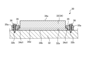
- FIG. 4 is a cross-sectional view showing an example of an attachment mechanism for the target 33 according to the embodiment.
- the target 33 can be attached to the arc cathode 32 using an attachment member 35 and a fixing member 36.
- the mounting member 35 is, for example, ring-shaped, and is configured so that the first portion 34c of the main body 34 can be inserted inside, and the protrusion 34d1 of the second portion 34d can be hooked and secured in place.
- the mounting member 35 also has multiple through holes 35a, and multiple fixing members 36 can be inserted into each of the multiple through holes 35a.
- the fixing member 36 is, for example, a bolt, which can be inserted through the through hole 35a and can be fixed (screwed) into the screw hole 32b located on the surface 32a of the arc cathode 32.
- the main body 34 of the target 33 has the protrusion 34d1, which makes it possible to easily attach the target 33 to the arc cathode 32.
- the thickness T2 of the second portion 34d of the main body portion 34 may be 2.1 (mm) to 3.5 (mm).
- the thickness T2 of the second portion 34d 2.1 (mm) or more, the strength of the protrusion 34d1 in the second portion 34d is improved, so that the second portion 34d is less likely to be damaged when the target 33 is fixed using the mounting member 35 (see FIG. 4) and the fixing member 36 (see FIG. 4).
- the target 33 can be attached even more easily.
- the ratio T1/T2 of the thickness T1 of the first portion 34c to the thickness T2 of the second portion 34d in the main body portion 34 may be 6.4 or less.
- the ratio T2/T1 of the thickness T2 to the thickness T1 may be 0.16 or more.
- the thickness T2 of the second portion 34d is made somewhat larger than the thickness T1 of the first portion 34c, the strength of the protrusion 34d1 in the second portion 34d is improved. Therefore, according to the embodiment, when the target 33 is fixed using the mounting member 35 (see FIG. 4) and the fixing member 36 (see FIG. 4), the second portion 34d is less likely to be damaged.
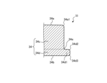
- FIG. 5 is an enlarged cross-sectional view showing an example of the configuration of the target 33 according to the embodiment.
- the corner 34d2 on the use surface 34a side of the protrusion 34d1 of the main body 34 and the corner 34d3 on the back surface 34b side of the protrusion 34d1 may both have a chamfered shape.
- the corners 34d2, 34d3 of the protrusion 34d1 may have an R shape or a C shape.
- the chamfer width of the corner 34d2 on the use surface 34a side may be larger than the chamfer width of the corner 34d3 on the back surface 34b side.
- chamfer width refers to the width of the chamfered portion in the direction perpendicular to the thickness direction of the main body 34 (the left-right direction in FIG. 3) in the cross section shown in FIG. 3.
- FIG. 3 shows a cross section perpendicular to the outer edges of the two main surfaces (usage surface 34a, back surface 34b) of main body 34
- the "chamfer width" may be interpreted as the width of the chamfered portion in a direction perpendicular to the outer edges of the two main surfaces (usage surface 34a, back surface 34b) when viewed in a plane of main body 34.
- the chamfer width of the corner 34d3 on the back surface 34b side may be greater than the chamfer width of the corner 34d2 on the use surface 34a side.
- This increases the contact area between the target 33 and the mounting member 35, allowing the target 33 to be stably fixed by the mounting member 35. Therefore, according to the embodiment, it is possible to reduce stress concentration on the target 33 due to the mounting member 35 when the target 33 is fixed.
- both corners 34d2 and 34d3 have a chamfered shape, but the present disclosure is not limited to such an example, and for example, either corner 34d2 or corner 34d3 may have a chamfered shape.
- the corner 34e located at the base end of the protrusion 34d1 between the first portion 34c and the second portion 34d may have an R-shaped curved surface. This makes it less likely that cracks will occur at the base end of the protrusion 34d1.
- the corners 34a1 located on the periphery of the use surface 34a may have a chamfered shape.
- the corners 34a1 may have an R shape or a C shape.
- the chamfer width of corner 34a1 may be smaller than the chamfer width of corner 34d2 and the chamfer width of corner 34d3. In this way, by reducing the chamfer width of corner 34a1, target 33 can be manufactured more easily.
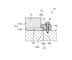
- FIG. 6 is an enlarged cross-sectional view showing an example of an attachment mechanism for the target 33 according to the embodiment.
- the distance ⁇ 1 between the outer surface of the first portion 34c and the inner surface of the attachment member 35 may be smaller than the distance ⁇ 2 between the outer surface of the protrusion 34d1 and the inner surface of the attachment member 35. This can reduce warping of the target 33 due to thermal expansion during use.
- the distance ⁇ 1 between the outer surface of the first portion 34c and the inner surface of the mounting member 35 may be greater than the distance ⁇ 2 between the outer surface of the protrusion 34d1 and the inner surface of the mounting member 35. This can reduce adhesion between the target 33 and the mounting member 35 caused by thermal expansion during use.
- the back surface 34b of the main body 34 may be cooled during film formation by contacting the front surface 32a of the arc cathode 32. This reduces an excessive rise in temperature of the usable surface 34a of the main body 34, making it possible to form a DLC thin film with a stable thickness on multiple workpieces W.
- a flow path may be located inside the arc cathode 32, and a cooling medium such as water may be passed through the flow path. This can further reduce excessive increases in temperature of the use surface 34a of the main body 34, making it possible to form DLC thin films of a more stable thickness on multiple workpieces W.
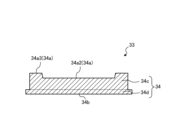
- FIG. 7 is a cross-sectional view showing an example of the configuration of a target 33 according to another embodiment. As shown in FIG. 7, in this another embodiment, a central portion 34a2 of a use surface 34a of a main body portion 34 may be recessed with respect to an outer periphery 34a3 of the use surface 34a.
- the use surface 34a of the main body 34 gradually drops from the position it was in when use began. This is because, as described above, when a coating containing the components of the target 33 is formed on the surface of the workpiece W, the use surface 34a melts and evaporates due to the vacuum arc discharge.
- the surface 34a in use does not necessarily wear down evenly across the entire surface, with the central portion 34a2 wearing down more than the peripheral portion 34a3. After some time has passed since the target 33 began to be used, when the central portion 34a2 has become recessed, the DLC thin film deposition process may become stable.
- the central portion 34a2 is recessed from the start of use, so that the DLC thin film deposition process is stable from the start of use.
- the bottom surface of the central portion 34a2 may be flat. This stabilizes the movement of the arc spot, making it easier for the arc discharge to occur uniformly.
- the bottom surface being flat does not necessarily have to be flat in the strict sense. It is sufficient that the surface roughness Ra (arithmetic mean roughness) of the bottom surface is about 50 ⁇ m or less.
- the surface roughness Ra may be evaluated based on JIS B 0601:2013.
- the present disclosure is not limited to such an example.
- the technology of the present disclosure may be applied to a film forming apparatus that forms a DLC thin film by various film forming methods (e.g., sputtering method, etc.).
- the target 33 may be approximately trapezoidal in cross section, with the back surface 34b being larger than the usable surface 34a. This also makes it possible to hook the mounting member 35 onto the side of the trapezoid, so that the target 33 can be fixed to the arc cathode 32 without any problems.
- the present technology can also be configured as follows.
- a disk-shaped body portion containing carbon is provided, The main body has a usable surface that evaporates during film formation, The diameter of the use surface is 50 (mm) to 150 (mm).
- the DLC film formation target according to (1) wherein the thickness of the main body portion is smaller than the diameter of the use surface.
- the main body portion has a back surface opposite to the use surface, The DLC film formation target according to (1) or (2), wherein the area of the back surface is larger than the area of the use surface.
- the main body portion has a first portion having the same area as the use surface in a plan view and a second portion having the same area as the back surface in a plan view,
- the second portion has a protruding portion protruding laterally, The DLC film formation target according to (4) or (5), wherein the corners of the protrusions have a chamfered shape.
Landscapes
- Chemical & Material Sciences (AREA)
- Chemical Kinetics & Catalysis (AREA)
- Engineering & Computer Science (AREA)
- Materials Engineering (AREA)
- Mechanical Engineering (AREA)
- Metallurgy (AREA)
- Organic Chemistry (AREA)
- Physical Vapour Deposition (AREA)
Priority Applications (2)
| Application Number | Priority Date | Filing Date | Title |
|---|---|---|---|
| JP2025529074A JPWO2025004211A1 (https=) | 2023-06-28 | 2023-06-28 | |
| PCT/JP2023/023937 WO2025004211A1 (ja) | 2023-06-28 | 2023-06-28 | Dlc成膜用ターゲット |
Applications Claiming Priority (1)
| Application Number | Priority Date | Filing Date | Title |
|---|---|---|---|
| PCT/JP2023/023937 WO2025004211A1 (ja) | 2023-06-28 | 2023-06-28 | Dlc成膜用ターゲット |
Publications (1)
| Publication Number | Publication Date |
|---|---|
| WO2025004211A1 true WO2025004211A1 (ja) | 2025-01-02 |
Family
ID=93937847
Family Applications (1)
| Application Number | Title | Priority Date | Filing Date |
|---|---|---|---|
| PCT/JP2023/023937 Ceased WO2025004211A1 (ja) | 2023-06-28 | 2023-06-28 | Dlc成膜用ターゲット |
Country Status (2)
| Country | Link |
|---|---|
| JP (1) | JPWO2025004211A1 (https=) |
| WO (1) | WO2025004211A1 (https=) |
Citations (3)
| Publication number | Priority date | Publication date | Assignee | Title |
|---|---|---|---|---|
| JP2011225995A (ja) * | 2011-04-25 | 2011-11-10 | Kobe Steel Ltd | ダイヤモンドライクカーボン硬質多層膜成形体の製造方法 |
| WO2016171247A1 (ja) * | 2015-04-22 | 2016-10-27 | 東洋炭素株式会社 | 炭素蒸発源 |
| WO2018105354A1 (ja) * | 2016-12-07 | 2018-06-14 | 株式会社神戸製鋼所 | 成膜装置およびそれを用いた成膜物の製造方法、ならびに冷却パネル |
-
2023
- 2023-06-28 WO PCT/JP2023/023937 patent/WO2025004211A1/ja not_active Ceased
- 2023-06-28 JP JP2025529074A patent/JPWO2025004211A1/ja active Pending
Patent Citations (3)
| Publication number | Priority date | Publication date | Assignee | Title |
|---|---|---|---|---|
| JP2011225995A (ja) * | 2011-04-25 | 2011-11-10 | Kobe Steel Ltd | ダイヤモンドライクカーボン硬質多層膜成形体の製造方法 |
| WO2016171247A1 (ja) * | 2015-04-22 | 2016-10-27 | 東洋炭素株式会社 | 炭素蒸発源 |
| WO2018105354A1 (ja) * | 2016-12-07 | 2018-06-14 | 株式会社神戸製鋼所 | 成膜装置およびそれを用いた成膜物の製造方法、ならびに冷却パネル |
Also Published As
| Publication number | Publication date |
|---|---|
| JPWO2025004211A1 (https=) | 2025-01-02 |
Similar Documents
| Publication | Publication Date | Title |
|---|---|---|
| US8687343B2 (en) | Substrate mounting table of substrate processing apparatus | |
| JPH01255666A (ja) | 迅速交換型の標的を有するスパッタ源及びアダプタリング | |
| US8685267B2 (en) | Substrate processing method | |
| CN100474401C (zh) | 磁记录介质的制造方法和制造装置 | |
| JP4995917B2 (ja) | 石英ガードリング | |
| JP2009188173A (ja) | 基板処理方法及び基板処理装置 | |
| JP7246154B2 (ja) | プラズマ処理装置及び静電吸着方法 | |
| JP2010114313A (ja) | リング状部材及びその製造方法 | |
| US20110228439A1 (en) | Substrate mounting and demounting method | |
| TWI829685B (zh) | 具有自定心特徵的兩件式快門盤組件 | |
| WO2025004211A1 (ja) | Dlc成膜用ターゲット | |
| JP2005307351A (ja) | スパッタ・ターゲット、スパッタ・ターゲット・アセンブリ及びそれらの製造方法 | |
| WO2024201924A1 (ja) | イオンプレーティング用ターゲット | |
| US20100155227A1 (en) | Sputtering apparatus and film forming method | |
| JP2019140357A (ja) | 被処理体の載置装置及び処理装置 | |
| JP2006079952A (ja) | 集束イオンビーム装置、及びそれに用いる絞り | |
| JP3104701B1 (ja) | アーク式蒸発源 | |
| JP2016129176A (ja) | 冷却構造及び平行平板エッチング装置 | |
| WO2014132308A1 (ja) | スパッタリング装置 | |
| JPH0377273B2 (https=) | ||
| KR102707659B1 (ko) | 스퍼터링 타겟 접합체 | |
| JP5049632B2 (ja) | フィラメント固定機構、発熱機構および蒸着装置 | |
| JP2005232488A (ja) | 気相成長装置 | |
| JP4943829B2 (ja) | ターゲット構成、デバイスを製造する方法、およびマグネトロンスパッタ供給源 | |
| JP4419622B2 (ja) | 磁気記録媒体の製造方法 |
Legal Events
| Date | Code | Title | Description |
|---|---|---|---|
| 121 | Ep: the epo has been informed by wipo that ep was designated in this application |
Ref document number: 23943609 Country of ref document: EP Kind code of ref document: A1 |
|
| ENP | Entry into the national phase |
Ref document number: 2025529074 Country of ref document: JP Kind code of ref document: A |
|
| WWE | Wipo information: entry into national phase |
Ref document number: 2025529074 Country of ref document: JP |
|
| NENP | Non-entry into the national phase |
Ref country code: DE |