WO2024257402A1 - 発電素子、これを用いた磁気センサ及びエンコーダー - Google Patents
発電素子、これを用いた磁気センサ及びエンコーダー Download PDFInfo
- Publication number
- WO2024257402A1 WO2024257402A1 PCT/JP2024/006013 JP2024006013W WO2024257402A1 WO 2024257402 A1 WO2024257402 A1 WO 2024257402A1 JP 2024006013 W JP2024006013 W JP 2024006013W WO 2024257402 A1 WO2024257402 A1 WO 2024257402A1
- Authority
- WO
- WIPO (PCT)
- Prior art keywords
- magnetic
- magnetic body
- power generating
- plate
- generating element
- Prior art date
- Legal status (The legal status is an assumption and is not a legal conclusion. Google has not performed a legal analysis and makes no representation as to the accuracy of the status listed.)
- Ceased
Links
Images



Classifications
-
- G—PHYSICS
- G01—MEASURING; TESTING
- G01R—MEASURING ELECTRIC VARIABLES; MEASURING MAGNETIC VARIABLES
- G01R33/00—Arrangements or instruments for measuring magnetic variables
- G01R33/02—Measuring direction or magnitude of magnetic fields or magnetic flux
-
- H—ELECTRICITY
- H02—GENERATION; CONVERSION OR DISTRIBUTION OF ELECTRIC POWER
- H02K—DYNAMO-ELECTRIC MACHINES
- H02K35/00—Generators with reciprocating, oscillating or vibrating coil system, magnet, armature or other part of the magnetic circuit
- H02K35/02—Generators with reciprocating, oscillating or vibrating coil system, magnet, armature or other part of the magnetic circuit with moving magnets and stationary coil systems
-
- H—ELECTRICITY
- H10—SEMICONDUCTOR DEVICES; ELECTRIC SOLID-STATE DEVICES NOT OTHERWISE PROVIDED FOR
- H10N—ELECTRIC SOLID-STATE DEVICES NOT OTHERWISE PROVIDED FOR
- H10N50/00—Galvanomagnetic devices
- H10N50/10—Magnetoresistive devices
Definitions
- This disclosure relates to a power generating element and a magnetic sensor and encoder that use the same.
- the Great Barkhausen effect is a phenomenon in which the direction of magnetization suddenly reverses in response to changes in an external magnetic field. If a generating coil made of conductive wire is placed around a magnetic material in which this Great Barkhausen effect occurs, and an external magnetic field is applied to reverse the direction of magnetization due to the Great Barkhausen effect, a generating element can be obtained in which an electromotive force is generated in the generating coil by electromagnetic induction.
- the magnetic field of the magnet when a generating element is placed in the magnetic field of a rotating magnet with two or more poles, for example if the magnetic body is long in the longitudinal direction, the magnetic field of the magnet may be applied only near the center of the magnetic body of the generating element. In that case, the large Barkhausen effect occurs only near the center of the magnetic body, making it difficult for it to occur simultaneously throughout the entire body, resulting in a problem of reduced power generation characteristics.
- the magnetic field generated by the Great Barkhausen effect in a magnetic material returns to the magnetic material through air, which is difficult for magnetic fields to pass through, so the change in the magnetic field is small, and there is a problem in that the generated voltage by electromagnetic induction is small.
- the present disclosure has been made to solve the problems described above, and aims to obtain a power generation element with improved power generation characteristics that can stably output a larger generated voltage.
- the power generating element of the present disclosure is The device comprises a magnetic body made of a magnetic material that produces a large Barkhausen effect, a power generation coil in which magnetic flux passing through the magnetic body is linked, and two soft magnetic bodies having an insertion portion through which the magnetic body is inserted and including a soft magnetic material provided at both ends of the magnetic body so that the magnetic body comes into contact with the magnetic body when inserted into the insertion portion, and generates an electromotive force in the power generation coil due to changes in the magnetic field of a magnetic field generating source, and is characterized in that a plate-shaped member is disposed between the magnetic body and the magnetic field generating source and between the two soft magnetic bodies to block the magnetic field generated from the magnetic field generating source toward the center of the magnetic body.
- the magnetic field generated by the magnetic field source near the center of the magnetic body is blocked by the plate-shaped member, so that the magnetic field is applied only near the center of the magnetic body, and the large Barkhausen effect is prevented from occurring only near the center of the magnetic body. This makes it possible to stably output a larger generated voltage, improving the power generation characteristics.
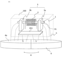
- FIG. 2 is a diagram showing a configuration of a power generating element according to the first embodiment
- 5 is a diagram showing the relationship between the length of the plate-shaped member of the power generating element and the shielding effect according to the first embodiment.
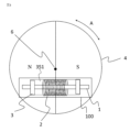
- FIG. 4 is a diagram showing the positional relationship between a magnetic field generation source and a power generation element according to the first embodiment;
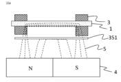
- FIG. 5A to 5C are diagrams illustrating the effect of the plate-shaped member of the power generating element according to the first embodiment.
- 10A to 10C are diagrams illustrating another effect of the plate-shaped member of the power generating element according to embodiment 1.
- 1 is a schematic cross-sectional view of a reflective optical encoder using a power generating element according to a first embodiment.
- 5A and 5B are diagrams illustrating an example of a magnetic body of a power generating element according to the first embodiment.
- 4A and 4B are diagrams illustrating an example of a soft magnetic material of a power generating element according to the first embodiment.
- 10A to 10C are diagrams illustrating an example of the structure of a plate-shaped member of a power generating element according to embodiment 2.
- 10A to 10C are diagrams illustrating an example of the structure of a plate-shaped member of a power generating element according to embodiment 2.
- 13A to 13C are diagrams illustrating an example of the structure of a power generating element according to embodiment 3.
- 13 is a schematic diagram showing the assembly of a power generating element according to embodiment 3.
- FIG. 13 is a schematic diagram showing the assembly of a power generating element according to embodiment 3.
- FIG. 11 is a schematic diagram illustrating an example of the structure of a power generating element according to embodiment 3.
- FIG. 11 is a schematic diagram illustrating an example of the structure of
- FIG. 1 shows the configuration of a power generating element 100 according to the first embodiment.
- a power generating coil 2 made of conductive wire is wound around a magnetic body 1 made of a magnetic material, and soft magnetic bodies 3 made of a soft magnetic material are arranged around the magnetic body 1 at both ends of the magnetic body 1.
- a magnetic field generating source 4 such as a magnet, is disposed near the magnetic body 1, generating a magnetic field 5 around the magnetic body 1.
- the magnetic body 1 used in the first embodiment can produce the large Barkhausen effect.
- the large Barkhausen effect is a phenomenon in which, when the magnetic body 1 is magnetized, the magnetic domain walls inside the magnetic body 1 move all at once, and the magnetization direction is reversed in an extremely short time.
- a Vicaloy alloy FeCoV alloy
- FeCoV alloy FeCoV alloy
- a Vicaloy alloy with a wire diameter of 0.1 mm to 1 mm is drawn into a wire shape, and then twisted to obtain a magnetic body 1 with a structure in which the coercive force is different between the outer periphery and the center. Note that this is an example and does not limit the wire diameter of the magnetic body 1.
- the power generating coil 2 is a coil in which a conductive wire is wound, and is disposed so as to wind around and surround the magnetic body 1, so that the magnetic flux passing through the magnetic body 1 is interlinked therewith.
- the magnetic flux inside the magnetic body 1 changes due to the large Barkhausen effect of the magnetic body 1, the magnetic flux passing through the power generation coil 2 changes. Therefore, an electromotive force is generated in the power generation coil 2 by electromagnetic induction, and the power generation element 100 can function.
- the power generating coil 2 using conductive wire can be made of copper wire with an insulating coating, and is formed by winding the wire around a bobbin.
- copper wire gold wire, silver wire, copper alloy wire, aluminum wire, aluminum alloy wire, etc. may also be used.
- the wire diameter of the conductive wire is selected based on the diameter of the magnetic body 1 to be wound, the size of the power generating element 100, etc.
- a magnetic field generating source 4 is arranged around the magnetic body 1.
- Two magnetic poles, an N pole and an S pole, are used as the magnetic field generating source 4 to generate a magnetic field 5.
- it is a circular, flat magnet that can rotate in the A direction.
- Half of the circular surface facing the generating element 100 is the N pole, and the other half is the S pole.
- it is also possible to use one or more pairs of two magnetic poles, an N pole and an S pole, as the magnetic field generating source 4 to generate the magnetic field 5. It is desirable that the magnetization direction of the magnetic field generating source 4 is a direction that intersects with the surface 4a of the magnetic field generating source 4 facing the generating element 100.
- the magnetic field generating source 4 is magnetized so that the magnetic flux exits from the surface constituting the N pole of the magnetic field generating source 4 to the side of the generating element 100 and enters from the generating element 100 side into the surface constituting the S pole.
- the magnetization direction is perpendicular or close to perpendicular to the surface 4a facing the generating element 100.
- this is an example and does not limit the magnetization direction.
- a permanent magnet as the magnetic field generating source 4.
- anything other than a permanent magnet can be used as long as it can generate a stable external magnetic field, and an electromagnet can also be used.
- a soft magnetic body 3 is disposed on each of both ends of the magnetic body 1 .
- the soft magnetic body 3 is configured to include a soft magnetic material in which magnetic pole reversal and the like easily occurs and which exhibits a lower coercive force than the magnetic body 1 used in the present embodiment 1. It is desirable that the soft magnetic body 3 has a higher magnetic permeability and a higher saturation magnetic flux density than the magnetic body 1.
- the soft magnetic body 3 has an insertion portion 31 through which the magnetic body 1 is inserted, and is configured to come into contact with the magnetic body 1 inside the insertion portion 31.
- the soft magnetic body 3 has a magnetic flux collecting effect that collects magnetic flux from the magnetic field generating source 4.
- the plate-shaped member 351 is made of the same soft magnetic material as the soft magnetic body 3.
- Cold-rolled steel plate is suitable as a soft magnetic material because it can be precisely processed into the desired shape and is inexpensive.
- Other materials that can be used include soft ferrite, permalloy, permendur, silicon steel, amorphous magnetic alloys, nanocrystalline magnetic alloys, and sendust.
- the plate-shaped member 351 can be made thin and easy to attach, which is also effective in reducing the size of the entire power generating element.
- the soft magnetic material may be processed into particles, which may then be incorporated into a plastic material or the like to form a plate.
- the plate-shaped member 351 does not need to be made of the same material as the soft magnetic body 3, and may be made of a magnetic material.
- the plate-shaped member 351 may also be made of a non-magnetic metal such as copper or aluminum. If the plate-shaped member 351 is made of a magnetic material, the magnetic collection effect may be too high, and the magnetic flux passing from the soft magnetic body 3 to the magnetic body 1 may be blocked. For this reason, the size (thickness, length, width) and gap may be changed to match the magnetic properties of the magnetic material used, to adjust the ease with which magnetic flux passes through the plate-shaped member 351.
- the plate-shaped member 351 may be constructed by combining a magnetic material with a non-magnetic material. This allows adjustment by combining a non-magnetic material, which would otherwise be too strong with a magnetic material alone and would block the magnetic flux passing from the soft magnetic material 3 to the magnetic material 1.
- the magnetic material can block the magnetic field even when the magnetic field source is rotating at a low speed, making it possible to increase the generated voltage.
- the cross-sectional area of the plate-shaped member 351 is smaller than that of the magnetic body 1, and the plate-shaped member 351 is formed from a thin plate. If the cross-sectional area is larger than that of the magnetic body 1, most of the magnetic field generated by the magnetic field generating source 4 passes through the plate-shaped member 351, and the magnetic field does not reach the magnetic body 1, resulting in a small generated voltage.
- the plate-like member 351 is disposed approximately parallel to the magnetic body 1 and between the magnetic field generating source 4 and the magnetic body 1.
- the longitudinal direction of the plate-like member 351 is configured to extend to a position covering the soft magnetic body 3.
- the plate-like member 351 does not need to extend to a position covering the soft magnetic body 3, and if it is approximately half the distance between the two soft magnetic bodies 3a, 3b, it has a shielding effect on the magnetic field from the magnetic field generating source 4 to the vicinity of the center of the magnetic body 1.
- the plate-like member 351 is disposed in a position facing the center of the magnetic body 1, the shielding effect on the magnetic field to the vicinity of the center of the magnetic body 1 will be large.
- the center and the vicinity of the center of the magnetic body 1 will be referred to as the center in the following description.
- FIG. 2 An example of the relationship between the length of plate-like member 351 and the shielding effect is shown in Figure 2. Even if the length is short, the presence of plate-like member 351 provides a shielding effect, and half the distance L between soft magnetic bodies 3a and 3b (L/2 in Figure 2) provides sufficient shielding effect. In addition, the shielding effect saturates at distances greater than L, so there is no need for plate-like member 351 to be longer than distance L.
- FIG. 3 shows the positional relationship between the magnetic field generating source 4 and the power generating element 100 according to the first embodiment, and is a top view of FIG.
- the magnetic field generating source 4 applies a magnetic field to the power generating element 100 by rotating about a rotation center 6.
- the power generating element 100 is disposed at a position where the magnetic body 1 of the power generating element 100 is radially displaced from the rotation center 6 of the magnetic field generating source 4 when viewed from the axial direction.
- the magnetic field generated by the magnetic field generating source 4 in the center of the magnetic body 1 is blocked by the plate-shaped member 351.
- the magnetic field from the magnetic field generating source 4 toward the center of the magnetic body 1 is returned directly to the magnetic field generating source 4 by the plate-shaped member 351, or is applied from the end of the plate-shaped member 351 through the soft magnetic body 3 to the end of the magnetic body 1 that is in contact with the soft magnetic body 3.
- the large Barkhausen effect occurs over a wide range of the magnetic body 1, improving the power generation performance and providing a stable output with small variations in the generated voltage.
- the plate-like member is made of a soft magnetic material or a magnetic material
- the magnetic field generated by the large Barkhausen effect of the magnetic material passes from the magnetic material 1 through the soft magnetic material 3, passes through the plate-like member 351, and returns from the soft magnetic material 3 to the magnetic material 1, as shown in Fig. 5, so that the magnetic flux passes easily and the change in the magnetic field becomes large, thereby making it possible to obtain a large generated voltage by the electromagnetic induction generated in the power generation coil 2.
- This makes it possible to provide a power generation element that can output a stable high voltage.
- the longitudinal direction of the plate-shaped member 351 is configured to extend to a position covering the soft magnetic material 3, but the vertical axis in Figure 2 may be replaced with the ease of passage of magnetic flux, and even if the plate-shaped member 351 is approximately half the distance L between the two soft magnetic materials 3a, 3b, when it is placed in the path of the magnetic flux, the magnetic resistance of that portion will be small, and more magnetic flux can pass through the power generation coil 2 than when the plate-shaped member 351 is not placed.
- a gap is provided between the plate-like member 351 and the soft magnetic bodies 3a and 3b, but by bringing the soft magnetic body 3 into contact with the plate-like member 351, the magnetic field passes through the soft magnetic body 3 without passing through the air, making it easier for the magnetic flux to pass, resulting in a larger generated voltage.
- the plate-like member 351 may be supported at a distance from the soft magnetic bodies 3a and 3b by surrounding it with a non-magnetic, non-conductive material, such as by molding the plate-like member 351 with resin or gluing it to a resin case.
- the electromotive force generated in the power generating element 100 can be used as a power source for driving an IC (Integrated Circuit).
- the power generated from the power generating coil 2 by electromagnetic induction is in the form of pulses, it can be used as a magnetic sensor that notifies the generation of the magnetic field 5 by a pulse voltage.
- the power generating coil 2 of the power generating element 100 can be connected to an IC, and the IC can operate using the power generated in pulses by the power generating element 100 as a power source, and at the same time, it can be used as a power-free magnetic sensor 50 that detects the generation of pulses by the power generating element 100 with the IC, and can also be used as a reflective optical encoder 200 equipped with a power-free magnetic sensor 50.
- a schematic cross-sectional view of the reflective optical encoder 200 is shown in Figure 6.
- the reflective optical encoder 200 is attached to a motor 51.
- a rotating shaft 53 is connected to a motor rotating shaft 52 of the motor 51, and a hub member 54 having a disk-shaped scale plate 55 attached thereto is fixed to the rotating shaft 53.
- the scale plate 55 is covered by a base plate 60, a housing 61 arranged around it, and a housing 62 through which the rotating shaft 53 passes.
- the base plate 60 is provided with a non-powered magnetic sensor 50 on its outer surface, and a light-emitting unit 57 that emits light as indicated by arrow 49 and a light-receiving unit 58 that receives reflected light as indicated by arrow 56 on its inner surface.
- Hub member 54 is provided with magnetism.
- magnet 59 is fixed to the back surface of hub member 54.
- Magnet 59 can also be placed between disk-shaped scale plate 55 and hub member 54. In this case, the process of fixing hub member 54 and magnet 59 can be omitted, improving production efficiency. Furthermore, by molding magnet 59 into the shape of hub member 54, magnet 59 has the function of hub member 54, so the number of constituent parts can be reduced and production efficiency can be improved.
- the hub member 54 can be made of a material such as plastic having magnetic particles dispersed therein, and the hub member 54 can be easily formed into various shapes by injection molding.
- the hub member 54 is not limited to a structure formed by dispersing magnetic particles in a plastic material, but may be formed from ferrite, alnico (Al-Ni-Co), or rare earth.
- the reflective optical encoder 200 when the rotating shaft 53 rotates, the light emitted from the light-emitting unit 57 is reflected by a pattern formed on the scale plate 55, which is composed of high-reflectivity areas and low-reflectivity areas, and the light-receiving unit 58 detects the change in the amount of reflected light, thereby detecting the rotation angle and rotation speed. Furthermore, the power generating element 100 generates power due to the change in the direction of the magnetic force emitted from the hub member 54, thereby detecting the number of rotations from the reference position.
- the reflective optical encoder 200 can detect the rotation angle, number of rotations, and rotation speed of the motor 51 by detecting the rotation angle, number of rotations, and rotation speed of the rotating shaft 53.
- the soft magnetic material can also be processed into particles and used by incorporating them into a plastic material.
- a soft magnetic body 3 made of this plastic material has the advantage that it can be easily formed into various shapes by injection molding, etc.
- the soft magnetic body 3 has been described as having a rectangular parallelepiped shape with holes, it may also be, for example, a soft magnetic body 3c with an elliptical cross-sectional shape as shown in FIG. 8(a), or a U-shaped soft magnetic body 3d as shown in FIG. 8(b).
- the soft magnetic bodies 3c and 3d are pressed and held against the magnetic body 1 by an adhesive (not shown), which allows stable contact between the magnetic body 1 and the soft magnetic bodies 3c and 3d, stabilizing the change in magnetization direction caused by the large Barkhausen effect in the magnetic body 1 and obtaining power generation characteristics with little fluctuation.
- Embodiment 2 In the first embodiment, an example was shown in which the plate-like member 351 was made of a thin plate and was arranged with a gap between it and the soft magnetic body 3, but in the second embodiment, as shown in Fig. 9, a notch 9 is provided in a predetermined range (hereinafter referred to as the central portion) from the center of the plate-like member 352, and both ends of the plate-like member 352 are formed so that their cross-sectional areas are larger than those of the central portion where the notch is formed. In addition, the soft magnetic body 3 and the plate-like member 352 are in contact with each other.
- a notch 9 is provided in a predetermined range (hereinafter referred to as the central portion) from the center of the plate-like member 352, and both ends of the plate-like member 352 are formed so that their cross-sectional areas are larger than those of the central portion where the notch is formed.
- the soft magnetic body 3 and the plate-like member 352 are in contact with each other.
- the magnetic path area in the center of the plate-shaped member 352 is reduced, thereby reducing the proportion of magnetic flux that returns directly to the magnetic field generating source 4 after passing through the plate-shaped member 352 without passing through the soft magnetic material 3, and by increasing the magnetic field applied to the magnetic material 1, the generated voltage is increased.
- the magnetic field generated near the center by the magnetic field generating source 4 passes more easily through the ends of the plate-shaped member 352, and the magnetic field applied from the ends of the plate-shaped member 352 through the soft magnetic body 3 to the ends of the magnetic body 1 is strengthened.
- the magnetic field passes through the soft magnetic body 3 without passing through the air, making it easier for the magnetic flux to pass through, and a larger generated voltage can be obtained.
- the plate-shaped member 353 may be formed such that the thickness of both ends of the plate-shaped member 353 is t, and the thickness is gradually reduced toward the length L/2.
- the plate-like members 352 and 353 may be fixed to the soft magnetic body by adhering them with an adhesive layer, for example.
- the magnetic resistance due to the slight gap caused by the adhesive layer is small, so that it is possible to obtain a large generated voltage in the same way as in the configuration in which the soft magnetic body 3 and the plate-like members 352 and 353 are arranged at intervals as in the first embodiment.
- the plate-shaped member 351 and the soft magnetic body 3 are separate members, but as shown in Fig. 11, the plate-shaped member 351A and the soft magnetic body 3A may be integrally formed in a U-shape. In this case, the thickness of the plate-shaped member 351A is made thinner than that of the soft magnetic body 3A. Compared to the plate-shaped members 352 and 353 shown in Figs. 9 and 10 simply contacting the soft magnetic body 3, air does not get into the boundary between the plate-shaped member 351A and the soft magnetic body 3, so the magnetic resistance is smaller, the magnetic flux of the magnetic field 5 passes more easily, a large generated voltage is obtained, and the number of parts can be reduced, resulting in a cost reduction effect.
- FIG. 12 is a schematic diagram of the assembly of the power generating element 100 of FIG. 11.
- the power generating coil 2 is positioned on the structure in which the plate-like member 351A and the soft magnetic body 3A are integrally formed, and the magnetic body 1 is inserted and fixed into the hole provided in the soft magnetic body 3A and into the hollow core portion inside the power generating coil 2.
- Members for positioning the power generating coil 2 and adhesive members for fixing the magnetic body 1 to the hole are omitted from the figure.
- FIG. 13 is another schematic diagram of the assembly of the power generating element 100 of FIG. 11.
- the upper part of the soft magnetic body 3B of the structure in which the plate-shaped member 351B and the soft magnetic body 3B are integrally formed is cut out into a U-shaped groove, and when the magnetic body 1 is inserted into the power generating coil 2, both ends of the magnetic body 1 may be inserted into the U-shaped groove from the top, arranged as shown in FIG. 14, and fixed to the soft magnetic body 3B.
- the positioning of the magnetic body 1 inserted into the power generating coil 2 and the structure for fixing the magnetic body 1 to the U-shaped groove are omitted. After inserting the magnetic body 1 into the U-shaped groove, it is appropriately determined whether or not to fill the groove.
- the structure of the power generating element of the third embodiment is easier to position and fix the magnetic body 1 than the case in which the plate-shaped member 351 and the magnetic body 1 are composed of separate members described in the first and second embodiments, and the number of assembly steps can be reduced, resulting in a cost reduction effect.
- appendices a magnetic body made of a magnetic material that produces a large Barkhausen effect;
- a power generating coil in which magnetic flux passing through the magnetic body interlinks;
- a power generating element including: an insertion portion through which the magnetic body is inserted; and two soft magnetic bodies including a soft magnetic material provided at both ends of the magnetic body so as to come into contact with the magnetic body by inserting the magnetic body into the insertion portion; and the power generating element generates an electromotive force in a power generating coil in response to a change in a magnetic field of a magnetic field generating source
- a power generating element characterized in that a plate-shaped member is arranged between the magnetic body and the magnetic field generating source, and between the two soft magnetic bodies, to block the magnetic field generated from the magnetic field generating source toward the center of the magnetic body.
Landscapes
- Physics & Mathematics (AREA)
- Engineering & Computer Science (AREA)
- Power Engineering (AREA)
- Condensed Matter Physics & Semiconductors (AREA)
- General Physics & Mathematics (AREA)
- Transmission And Conversion Of Sensor Element Output (AREA)
Priority Applications (1)
| Application Number | Priority Date | Filing Date | Title |
|---|---|---|---|
| JP2025527449A JPWO2024257402A1 (https=) | 2023-06-14 | 2024-02-20 |
Applications Claiming Priority (2)
| Application Number | Priority Date | Filing Date | Title |
|---|---|---|---|
| JP2023097413 | 2023-06-14 | ||
| JP2023-097413 | 2023-06-14 |
Publications (1)
| Publication Number | Publication Date |
|---|---|
| WO2024257402A1 true WO2024257402A1 (ja) | 2024-12-19 |
Family
ID=93851731
Family Applications (1)
| Application Number | Title | Priority Date | Filing Date |
|---|---|---|---|
| PCT/JP2024/006013 Ceased WO2024257402A1 (ja) | 2023-06-14 | 2024-02-20 | 発電素子、これを用いた磁気センサ及びエンコーダー |
Country Status (2)
| Country | Link |
|---|---|
| JP (1) | JPWO2024257402A1 (https=) |
| WO (1) | WO2024257402A1 (https=) |
Citations (5)
| Publication number | Priority date | Publication date | Assignee | Title |
|---|---|---|---|---|
| US4217512A (en) * | 1978-04-19 | 1980-08-12 | Robert Bosch Gmbh | Apparatus for generating a pulse when a first member passes a second member using permanent magnets with different strengths |
| JP2016144335A (ja) * | 2015-02-03 | 2016-08-08 | 浜松光電株式会社 | 起電力発生装置 |
| JP2022079329A (ja) * | 2020-11-16 | 2022-05-26 | パナソニックIpマネジメント株式会社 | エンコーダ |
| JP7109713B1 (ja) * | 2021-01-12 | 2022-07-29 | 三菱電機株式会社 | 発電素子、磁気センサ、エンコーダおよびモータ |
| WO2022244088A1 (ja) * | 2021-05-18 | 2022-11-24 | 三菱電機株式会社 | 発電モジュール |
-
2024
- 2024-02-20 WO PCT/JP2024/006013 patent/WO2024257402A1/ja not_active Ceased
- 2024-02-20 JP JP2025527449A patent/JPWO2024257402A1/ja active Pending
Patent Citations (5)
| Publication number | Priority date | Publication date | Assignee | Title |
|---|---|---|---|---|
| US4217512A (en) * | 1978-04-19 | 1980-08-12 | Robert Bosch Gmbh | Apparatus for generating a pulse when a first member passes a second member using permanent magnets with different strengths |
| JP2016144335A (ja) * | 2015-02-03 | 2016-08-08 | 浜松光電株式会社 | 起電力発生装置 |
| JP2022079329A (ja) * | 2020-11-16 | 2022-05-26 | パナソニックIpマネジメント株式会社 | エンコーダ |
| JP7109713B1 (ja) * | 2021-01-12 | 2022-07-29 | 三菱電機株式会社 | 発電素子、磁気センサ、エンコーダおよびモータ |
| WO2022244088A1 (ja) * | 2021-05-18 | 2022-11-24 | 三菱電機株式会社 | 発電モジュール |
Also Published As
| Publication number | Publication date |
|---|---|
| JPWO2024257402A1 (https=) | 2024-12-19 |
Similar Documents
| Publication | Publication Date | Title |
|---|---|---|
| JP7378586B2 (ja) | 発電素子、これを用いた磁気センサ、エンコーダおよびモータ | |
| JP7109713B1 (ja) | 発電素子、磁気センサ、エンコーダおよびモータ | |
| WO2022230651A1 (ja) | 発電素子、エンコーダおよび磁性部材の製造方法 | |
| JP4811785B2 (ja) | 周期磁界発生装置およびこれを用いたリニアモータ | |
| JPH0831635A (ja) | Mri用磁界発生装置 | |
| JPWO2022153861A5 (https=) | ||
| WO2022230652A1 (ja) | 発電素子、エンコーダ、磁性部材の製造方法および信号取得方法 | |
| JPWO2022230652A5 (https=) | ||
| JP3755071B2 (ja) | 面移動アクチュエータ | |
| JPH07503359A (ja) | 強磁性ワイヤ電磁アクチュエータ | |
| WO2024257402A1 (ja) | 発電素子、これを用いた磁気センサ及びエンコーダー | |
| US4884235A (en) | Micromagnetic memory package | |
| JP2010040914A (ja) | 多極磁石の着磁方法、多極磁石及びそれを用いた磁気式エンコーダ | |
| JP2012205450A (ja) | 振動発電機 | |
| US20250132641A1 (en) | Power generation element, power generation system, and encoder | |
| JP2007225536A (ja) | 回転運動検出装置 | |
| JP2007502183A (ja) | 核磁気共鳴装置に適用可能な磁場発生システム | |
| JPH0644385U (ja) | 可動磁石式アクチュエータ | |
| JP2001351816A (ja) | 着磁ヨーク装置とそれを使用して着磁されたマグネットを使用したモータ | |
| JPH06189518A (ja) | リニアモータ | |
| JP2011119621A (ja) | 着磁装置及び着磁ヘッド | |
| WO2024075465A1 (ja) | 発電素子、発電システムおよびエンコーダ | |
| JPS5844896A (ja) | ム−ビングコイル型カ−トリツジ | |
| WO2024202919A1 (ja) | 発電素子、発電システム、及びエンコーダ | |
| JP2009268330A (ja) | コアレスモータ |
Legal Events
| Date | Code | Title | Description |
|---|---|---|---|
| 121 | Ep: the epo has been informed by wipo that ep was designated in this application |
Ref document number: 24823025 Country of ref document: EP Kind code of ref document: A1 |
|
| WWE | Wipo information: entry into national phase |
Ref document number: 2025527449 Country of ref document: JP |
|
| NENP | Non-entry into the national phase |
Ref country code: DE |