WO2024252962A1 - インシュレータ、回転電機のステータ、回転電機、および回転電機のステータの製造方法 - Google Patents
インシュレータ、回転電機のステータ、回転電機、および回転電機のステータの製造方法 Download PDFInfo
- Publication number
- WO2024252962A1 WO2024252962A1 PCT/JP2024/019263 JP2024019263W WO2024252962A1 WO 2024252962 A1 WO2024252962 A1 WO 2024252962A1 JP 2024019263 W JP2024019263 W JP 2024019263W WO 2024252962 A1 WO2024252962 A1 WO 2024252962A1
- Authority
- WO
- WIPO (PCT)
- Prior art keywords
- circumferential direction
- core
- stator
- insulator
- split
- Prior art date
- Legal status (The legal status is an assumption and is not a legal conclusion. Google has not performed a legal analysis and makes no representation as to the accuracy of the status listed.)
- Pending
Links
Images


Classifications
-
- H—ELECTRICITY
- H02—GENERATION; CONVERSION OR DISTRIBUTION OF ELECTRIC POWER
- H02K—DYNAMO-ELECTRIC MACHINES
- H02K3/00—Details of windings
- H02K3/46—Fastening of windings on the stator or rotor structure
Definitions
- This disclosure relates to an insulator, a stator for a rotating electric machine, a rotating electric machine, and a method for manufacturing a stator for a rotating electric machine.
- each split core is combined with an insulator of a shape corresponding to its shape, and a coil is wound around the teeth of each split core via the insulator. Adjacent insulators are connected to each other by connecting parts formed on each insulator, and a rotating electrical machine stator equipped with an insulator of the following configuration has been devised.
- a first insulator member and a second insulator member each having a connecting rotation part at both circumferential ends, are combined with each split core, and the split core combined with the first insulator member and the split core combined with the second insulator member are arranged alternately in the circumferential direction.
- the connecting rotation parts at both circumferential ends of the first insulator have connecting protrusions that protrude in the axial direction
- the connecting rotation parts at both circumferential ends of the second insulator have connecting recesses that are recessed in the axial direction.
- the connecting recesses have openings that open radially outward.
- the connecting protrusion of the first insulator member is inserted into and engaged with the connecting recess of the second insulator member while being elastically deformed so as to widen the opening width of the connecting recess. Since the connecting recess of the second insulator member is elastically deformed so as to widen its opening width, the rigidity of the connecting portion against the load generated in the circumferential direction is low. Therefore, there is a problem that the split cores may be misaligned in the circumferential direction, which may increase the outer diameter of the stator or reduce its roundness.
- the present disclosure discloses techniques for solving the problems described above, and aims to provide an insulator that can suppress change in the outer diameter of a stator and ensure its roundness, a stator for a rotating electric machine in which change in the outer diameter is suppressed and roundness is ensured, a rotating electric machine in which high performance is ensured, and a method for manufacturing a stator for such a rotating electric machine.
- the insulator of the present disclosure comprises: An insulator that is attached to a split core having a back yoke portion extending in a circumferential direction and teeth protruding radially inward from the back yoke portion, and electrically insulates a wound coil from the split core, an engagement portion is formed on each of the axial end surfaces of the back yoke portion on both circumferential sides thereof to connect the split cores adjacent to each other in the circumferential direction, Each of the engaging portions of the insulators is configured to be engageable with the engaging portions of the other insulators adjacent thereto in the circumferential direction only from the axial direction side. It is something.
- the stator of the rotating electric machine includes: In a stator for a rotating electric machine, the coil is wound around the teeth of each of the split cores to which the insulator configured as described above is attached, and the split cores are connected in an annular shape by the engaging portions, a frame or a molding resin is provided to cover the outer periphery of the split cores connected in an annular shape; A pressing force from a radially outer side to a radially inner side is applied to each of the divided cores by the frame or the molding resin. It is something.
- the rotating electric machine of the present disclosure includes: a stator of a rotating electric machine configured as described above; A rotor arranged coaxially with the stator. It is something.
- a method for manufacturing a stator of a rotating electric machine includes the steps of: A method for manufacturing a stator for a rotating electric machine, comprising a connecting step of arranging the split cores, to which the insulators configured as described above are attached, in an annular shape, and connecting the split cores adjacent in a circumferential direction by the engaging portions to form a core connected body,
- the split cores constituting both ends of the core connected body are brought close to each other in the circumferential direction, and the split core having the convex portion at one end of the brought-close core connected body is slid axially upward so as to be positioned above the concave portion at the other end, and with the core side surfaces of the split cores constituting both ends of the core connected body in contact with each other, the convex portion is inserted into the concave portion from the axially upward side to engage the concave portion with the convex portion; It is something.
- the insulator and the stator for a rotating electric machine of the present disclosure it is possible to obtain an insulator and a stator for a rotating electric machine that can suppress changes in the outer diameter of the stator and ensure its roundness. Furthermore, according to the rotating electric machine and the method for manufacturing the stator of the rotating electric machine disclosed herein, high performance of the rotating electric machine can be ensured.
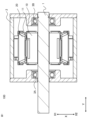
- FIG. 1 is a cross-sectional view showing an example of a schematic configuration of a rotating electric machine according to a first embodiment.
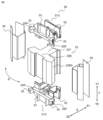
- 2 is an exploded perspective view showing a split core constituting a stator core of the stator according to the first embodiment and an insulating portion attached to the split core;
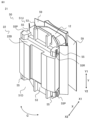
- FIG. 1 is a perspective view showing a coil winding body according to a first embodiment;
- 4 is an enlarged top view showing an engagement portion of the insulator according to the first embodiment.
- FIG. 4 is a top view showing a state in which the engaging portions of the insulator according to the first embodiment are engaged;
- FIG. 6A and 6B are diagrams illustrating the direction of a repulsive force that occurs when an insulating film is folded when the insulator according to the first embodiment is engaged.
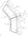
- FIG. 1 is a perspective view showing a state in which coil wound bodies according to embodiment 1 are connected to each other;
- FIG. 1 is an enlarged perspective view showing a state in which coil wound bodies according to the first embodiment are connected to each other;
- FIG. 13 is a top view showing another configuration of the engagement portion of the insulator according to embodiment 1.
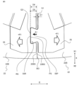
- FIG. 4 is a cross-sectional view showing another configuration example of the rotating electric machine according to the first embodiment.
- FIG. FIG. 11 is a perspective view showing a schematic configuration of an engagement portion of an insulator according to a second embodiment.
- FIG. 11 is a perspective view showing a schematic configuration of an engagement portion of an insulator according to a second embodiment.
- 13 is a perspective view showing a state in which coil wound bodies according to embodiment 3 are connected to each other.
- FIG. 13 is an enlarged perspective view of an engagement portion when the coil wound bodies according to the third embodiment are connected to each other.
- FIG. 13 is a perspective view showing a state in which coil wound bodies according
- FIG. 1 is a cross-sectional view showing an example of a schematic configuration of a rotating electric machine 100 according to the first embodiment.
- the rotating electric machine 100 includes a rotor 10 fixed to a shaft 1 serving as a rotating shaft, and a stator 20 arranged concentrically with the rotor 10 and outside the rotor 10 in the radial direction X.
- the rotor 10 and the stator 20 are housed inside a hollow frame 2.
- the circumferential direction, radial direction, and axial direction of the rotating shaft of the annular stator 20 are respectively referred to as the circumferential direction C, the radial direction X, and the axial direction Y.
- the circumferential inner side of the yoke portion of the split core constituting the stator 20 refers to the central side of the yoke portion where the teeth are present.
- the circumferential outer side of the back yoke portion of the split core refers to the end side where the teeth are not present in the back yoke portion, or the direction circumferentially outer than this end.
- the axially upper side may be referred to as the axially outer side
- the axially lower side may be referred to as the axially inner side.
- the rotor 10 is equipped with a magnet 11 fixed inside the rotor 10.
- the shaft 1 to which the rotor 10 is fixed is rotatably supported by a first bearing 3A located on the output side of the shaft 1 and a second bearing 3B located on the opposite side to the output side, both of which are fixed within a frame 2.
- FIG. 2 is an exploded perspective view showing split cores 22 that constitute the stator core of stator 20 according to the first embodiment, and insulating parts 50 that are attached to split cores 22.
- the split cores 22 are obtained by dividing an annular stator core of an inner rotor type rotating electric machine 100 in the circumferential direction C by a set number of slots.
- the insulating portion 50 is attached to the split core 22 and electrically insulates the wound coil from the split core 22 .
- the split core 22 has a back yoke portion 22B extending in the circumferential direction C, and teeth portions 22T protruding radially inward X1 from an inner circumferential surface of a central portion in the circumferential direction C of the back yoke portion 22B.
- the core side surfaces 22BS of the opposing back yoke portions 22B have a planar shape along the radial direction X. Therefore, each split core 22 does not have the function of joining or holding the adjacent split cores 22 together.
- each split core 22 is configured in such a simple shape, it is only necessary to prepare one type of mold for the split cores 22, and manufacturing is easy.
- the insulating portion 50 is formed of an insulating material with a low elastic modulus, such as resin, and has a shape that fits the teeth portion 22T of the split core 22 so as to be fitted into the split core 22 for assembly.
- the insulating portion 50 comprises a first insulator 51U fitted to the axial upper side Y1 of the split core 22, a second insulator 51D fitted to the axial lower side Y2 of the split core 22, and an insulating film 59 covering both circumferential sides of the tooth portion 22T of the split core 22.
- the first insulator 51U and the second insulator 51D are the same parts having the same shape and function. However, when it is necessary to distinguish between the insulators 51 on the axial upper side Y1 and the axial lower side Y2 of the split core 22, they are referred to as the first insulator 51U and the second insulator 51D, and when there is no need to distinguish between them, they are referred to as the insulator 51.
- Each insulator 51 has a coil winding portion 52 , a back yoke covering portion 53 , and an engagement portion 55 .
- the coil winding portion 52 is arranged so as to overlap the tooth portion 22T of the split core 22 when viewed from the axial direction Y, and covers most of the end surface in the axial direction Y of the tooth portion 22T.
- the back yoke covering portion 53 covers most of the end face in the axial direction Y of the back yoke portion 22B.
- the engagement portions 55 are formed on both sides of the back yoke covering portion 53 in the circumferential direction C, and their detailed configuration will be described later, but they have a shape that can engage with the engagement portions 55 of other split cores 22 adjacent to them in the circumferential direction C.
- the insulating film 59 is attached along the circumferential C side of the teeth 22T of the split core 22, which forms the inner circumferential surface of the slot formed between adjacent teeth 22T in the circumferential C, the radial X inner surface of the back yoke portion 22B, and the radial X outer surface of the portion of the teeth 22T that protrudes circumferentially outward from the radial inner end.
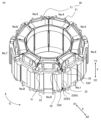
- FIG. 3 is a perspective view showing a coil winding body 21 formed by winding the coil 12 via the insulating section 50 around the split core 22 to which the insulating section 50 constructed as described above is attached.
- the stator 20 of the present embodiment is configured by connecting a plurality of the coil winding bodies 21 in an annular shape.
- the back yoke covering portion 53 of the insulator 51 does not cover the radially outer side X2 of the back yoke portion 22B of the split core 22.
- the stator 20 formed in this manner is fixed to the inner peripheral surface of the frame 2 .
- the stator 20 is excited, and the rotor 10 disposed inside the stator 20 rotates.
- the rotating electrical machine 100 is not limited to an electric motor, but may be a generator.
- FIG. 4 is an enlarged top view showing the engaging portions 55 of the insulators 51 of the coil winding bodies 21 adjacent to each other in the circumferential direction C.
- the engaging portions 55 are not engaged with each other, that is, the coil winding bodies 21 are not connected to each other.
- FIG. 5 is a top view showing a state in which the engaging portions 55 of the insulators 51 of the coil winding bodies 21 adjacent to each other in the circumferential direction C are engaged with each other, and the coil winding bodies 21 are connected to each other.
- the back yoke covering portion 53 of the insulator 51 is provided with the engaging portions 55 at both ends in the circumferential direction C.
- the engaging portion 55 on one circumferential side of the insulator 51 is formed with a convex portion 55P as a convex portion that protrudes in a set shape toward the circumferential outside, and the engaging portion 55 on the other circumferential side is formed with a concave portion 55R as a recess that is recessed in a set shape toward the circumferential inside and penetrates in the axial direction Y. Therefore, as shown in FIG. 4, between the coil winding bodies 21 adjacent to each other in the circumferential direction C, the convex portion 55P and the concave portion 55R of the engagement portion 55 of the insulator 51 provided on each of the coil winding bodies 21 face each other.
- the concave portion 55R penetrates in the axial direction Y, and is therefore open on its axial upper side (axial outer side) Y1.
- This shape allows the insulators 51 adjacent to each other in the circumferential direction C to be engaged with each other from the axial direction Y. As will be described later, this shape also allows for an engagement state in which at least the split cores 22 are fixed to each other so as not to move away from each other in the circumferential direction C. In this manner, the first insulators 51U and the second insulators 51D are connected to each other by the engagement between the concave portions 55R and the convex portions 55P formed on each insulator.
- the configuration of the concave portions 55R and the convex portions 55P, and the connection structure of the insulators 51 formed by the engagement between the concave portions 55R and the convex portions 55P will be described below.
- the recessed portions 55R are formed so that the radial width D2 on the circumferentially inner side is larger than the radial width D1 at the opening.
- the radial side surface of the tip portion of the convex portion 55P is formed in a shape that follows the inner walls on both sides in the radial direction X of the concave portion 55R, and therefore the radial width D4 on the tip portion side in the radial direction X is formed to be larger than the radial width D3 on the circumferentially inner side.
- the concave portion 55R is formed to have a narrower opening than the inner side, with the minimum width D1 in the radial direction X located at the opening side and the maximum width D2 in the radial direction located at the inner side.
- the convex portion 55P is formed to have a narrower opening than the inner side, with the maximum width D4 located at the tip portion side and the minimum width D3 in the radial direction X located at the circumferentially inner root side.
- the width of the concave portion 55R in the radial direction X is designed to be equal to or slightly smaller than the width of the convex portion 55P in the radial direction X by a dimensional tolerance.
- the concave portion 55R is formed in a shape called a "dovetail shape” in which the opening is narrow and the width in the radial direction X gradually increases from the opening toward the circumferentially inward direction.
- the convex portion 55P is formed in a shape called a "dovetail shape” in which the width in the radial direction X gradually increases toward the circumferentially outward direction.
- the convex portion 55P having the above-mentioned shape protrudes circumferentially outward from the core side surface 22BS on the circumferential direction C side of the split core 22. Therefore, the convex portion 55P of the insulator 51 assembled to each split core 22 overlaps in the axial direction Y with at least a portion of the other split core 22 adjacent to that split core 22.
- the coil winding 21 on the convex portion 55P side is slid toward the axially upper side Y1 to bring the core side surfaces 22BS of the adjacent split cores 22 into contact with each other, while the convex portion 55P is inserted from above the concave portion 55R to engage them.
- the width in the radial direction X of the concave portion 55R is formed to be the same as or slightly smaller than the width in the radial direction X of the convex portion 55P. Therefore, the convex portion 55P is lightly pressed into the concave portion 55R while slightly expanding the concave portion 55R in the radial direction X.
- This state in which the convex portion 55P is fitted into the concave portion 55R is the state in which the concave portion 55R and the convex portion 55P are engaged (hereinafter, sometimes simply referred to as the "engaged state").
- the concave portion 55R is formed at a position that substantially overlaps with the opposing convex portion 55P in the axial direction Y.
- the concave portion 55R and the convex portion 55P are positioned so as to almost overlap in the axial direction Y, more specifically, when the core side surfaces 22BS are in contact with each other, the concave portion 55R is shifted in the circumferential direction C relative to the convex portion 55P in a direction away from the boundary surface BO where the core side surfaces 22BS are in contact with each other.
- the length D5 in the circumferential direction C from the boundary surface BO to the bottom surface of the concave-shaped portion 55R is longer than the length D6 in the circumferential direction C from the boundary surface BO to the circumferentially outermost tip of the convex-shaped portion 55P. Therefore, in order to insert the tip portion of the convex portion 55P, which is formed to have the same shape as the inner wall of the concave portion 55R, into the concave portion 55R, the convex portion 55P is pulled in the direction of arrow A1 in Figure 5 beyond the boundary surface BO and then inserted into the concave portion 55R.
- each insulator 51 is formed so that a gap G1 having a set width D7 in the circumferential direction C is secured between the side surfaces of adjacent insulators 51. Therefore, when the concave portion 55R and the convex portion 55P are engaged, a tensile load F1 (+F1, -F1) in the circumferential direction C is generated in the engagement portion 55 such that the concave portion 55R is pulled toward the convex portion 55P (load -F1) and the convex portion 55P is pulled toward the concave portion 55R (load +F1).
- a preload is generated in a direction that maintains the tight contact between the core side surfaces 22BS, which are the mating surfaces of the split cores 22.
- the core side surfaces 22BS which are the mating surfaces of the split cores 22.
- the outer gradient portion PX2 on the radially outer side X2 of the convex portion 55P and the inner gradient portion PX1 on the radially inner side X1 of the convex portion 55P are in surface-to-surface contact with the outer gradient portion RX2 on the radially outer side X2 of the concave portion 55R and the inner gradient portion RX1 on the radially inner side X1 of the concave portion 55R.
- the gradient portions of the convex portion 55P and the concave portion 55R are in constant contact with each other, making it possible to fix the convex portion 55P in the radial direction X as well as in the circumferential direction C.
- the bottom surface RS of the concave portion 55R and the tip surface PS of the convex portion 55P do not make contact when engaged.
- the concave portion 55R is formed so that when engaged, it is displaced away from the convex portion 55P in the circumferential direction C, and a tensile load is applied that pulls them together, creating a gap G2 between the bottom surface RS of the concave portion 55R and the tip surface PS of the convex portion 55P.
- FIG. 6 is a diagram showing the direction of the repulsive force that occurs when the insulating film 59 is folded when the insulator 51 of this embodiment is engaged.
- the insulating film 59 is composed of an outer film 59O and an inner film 59I. 6, the outer film 59O is folded so as to overlap the inner film 59I.
- a gap G2 is created between the bottom surface RS of the concave portion 55R and the tip surface PS of the convex portion 55P so that the tensile load F1 is greater than the load F2, which is the repulsive force that pushes back in the circumferential direction when the insulating films 59 attached to adjacent split cores 22 come into contact with each other.
- the length D5 in the circumferential direction C from the boundary surface BO to the bottom surface of the concave portion 55R and the length D6 in the circumferential direction C from the boundary surface BO to the tip surface of the convex portion 55P at the outermost side in the circumferential direction are adjusted so that the tensile load F1 is greater than the repulsive force F2.
- the dimensions are designed so that the maximum strain generated in the engaging portion 55 does not exceed the breaking strain when subjected to a load caused by light press-fitting when the convex portion 55P is inserted into the concave portion 55R, and a circumferential tensile load that pulls the convex portion 55P toward the concave portion 55R.
- the outer gradient portion PX2 and the inner gradient portion PX1 of the convex portion 55P are in contact with the surfaces of the outer gradient portion RX2 and the inner gradient portion RX1 of the concave portion 55R.
- the convex portion 55P is sandwiched between the outer gradient portion RX2 and the inner gradient portion RX1 of the concave portion 55R. This results in the convex portion 55P being held in a state in which it is enveloped within the concave portion 55R, which has a narrow opening.
- the axial upper side Y1 of the stator 20 is formed by connecting the first insulators 51U to each other, and the axial lower side Y2 of the stator 20 is formed by connecting the second insulators 51D to each other.
- the first insulators 51U and the second insulators 51D have exactly the same shape.
- the concave portion 55R and the convex portion 55P are located at diagonal corners of the split core 22 when the split core 22 is viewed from the radially outer side X2.
- the connection structure in the axial direction Y between the split core 22 and the adjacent split core 22 is different between one circumferential side and the other circumferential side of the back yoke portion 22B.
- the first insulator 51U and the second insulator 51D have been described as having the same shape, but even if the first insulator 51U and the second insulator 51D have different shapes, it is possible to position the concave portion 55R and the convex portion 55P at diagonal corners of the split core 22.
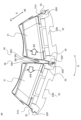
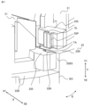
- FIG. 7 is a perspective view showing a state in which coil wound bodies 21 according to the first embodiment are connected to each other.
- FIG. 8 is an enlarged perspective view showing a state in which coil wound bodies 21 according to the first embodiment are connected to each other.
- the stator 20 of the present embodiment is configured with nine coil winding bodies 21 (split cores 22), but is not limited to this number.
- the nine coil winding bodies 21 may be referred to as the first coil winding body 21 through the ninth coil winding body 21 to distinguish them from one another. Also, in the figures, the positions corresponding to the first coil winding body 21 through the ninth coil winding body 21 are numbered No. 1 through No. 9.
- a winding body forming process is performed in which the insulating portion 50 is attached to the split core 22, and then the coil 12 is wound around the split core 22 to form nine coil winding bodies 21.
- a connecting step is performed in which the nine formed coil winding bodies 21 are arranged in an annular shape, and adjacent split cores 22 in the circumferential direction C are connected by their respective engaging portions 55 to form a core connected body 30 .
- the core connected body 30 shown in FIG. 7 is one in which all of the engaging portions 55 are engaged with each other, except for one engagement between the first coil winding body 21 (No. 1) and the ninth coil winding body 21 (No. 9).
- the coil winding body 21 is moved from a state in which the core side surfaces 22BS of the split cores 22 of the already engaged coil winding body 21 are in contact to an engagement position in which the coils 12 of the coil winding body 21 are slightly spaced apart. Then, as shown in FIG. 7, the space between the first coil winding body 21 (No. 1) and the ninth coil winding body 21 (No. 9) is opened in the circumferential direction C.
- the split core 22 of the first coil winding body 21 (No. 1) constituting one end side of the core connection body 30 and the split core 22 of the first coil winding body 21 (No. 9) constituting the other end side are brought into close proximity in the circumferential direction C.
- the split core 22 of the first coil winding body 21 (No. 1) having a convex portion 55P on one end side of the core connecting body 30 is slid axially upward Y1 while maintaining the engagement between the split core 22 of this first coil winding body 21 (No. 1) and the second coil winding body 21 (No.
- the core side surfaces 22BS of the split cores 22 of the first coil winding body 21 and the ninth coil winding body 21 are brought into contact with each other.
- the first coil winding body 21 (No. 1) is slid axially downward Y2, and the convex portion 55P of the first coil winding body 21 is inserted axially into the concave portion 55R of the ninth coil winding body 21 (No. 9).
- the tip side of the convex portion 55P of the first coil winding body 21 (No. 1) is pulled in the circumferential direction C from the boundary surface BO toward the concave portion 55R, while the convex portion 55P is inserted into the concave portion 55R from the axial direction Y.
- the convex portion 55P of the first coil winding body 21 (No. 1) and the concave portion 55R of the ninth coil winding body 21 (No. 9) are engaged, and the stator 20 is completed.
- a torsional load is generated in each convex portion 55P and each concave portion 55R in the stator 20, but the dimensions are designed so that the maximum strain generated in the engagement portion 55 does not exceed the fracture strain.
- a dedicated jig that can reproduce the manufacturing method described above may be used as a means of engagement. When using a jig, material and design costs are incurred, but workability can be improved.
- the completed stator 20 is press-fitted or shrink-fitted into a cylindrical frame 2 as shown in FIG. 1.
- the frame 2 may be a steel plate frame or may be integrally molded from resin, and the stator 20 is compatible with frames of all configurations.
- first bearing 3A and the second bearing 3B are press-fitted or shrink-fitted onto the shaft 1.
- the rotor 10 is inserted into the frame 2 in which the stator 20 is mounted.
- the bracket is inserted and the first bearing 3A and the second bearing 3B are fixed, and the rotating electric machine 100 is completed.
- the engaging portion of the insulator 51 is located radially inward X1 from the outer periphery of the split core 22, it can be press-fitted or shrink-fitted into the simple cylindrical frame 2, allowing for a simple assembly method to be selected. Since the frame 2 holds the stator 20 core, the connecting force of the insulator 51 is sufficient if it can withstand transportation up to the shrink-fitting process. In addition, the preload created by the interference of the press fit and shrink fit ensures that the core side surfaces 22BS, which are the mating surfaces of the split cores 22, come into even contact with each other, thereby ensuring the roundness of the inner circumferential surface of the radially inner portion of the stator 20.
- the workability of the ring assembly is improved by using the insulators 51 of the same shape on the top and bottom and engaging them in the axial direction Y, while the engaging portions 55 are engaged with each other without being inserted or removed in the circumferential direction C, so that the expansion of the outer diameter of the stator 20 due to the load generated in the circumferential direction C can be restricted, improving the workability of the frame shrink fitting.
- FIG. 9 is a top view showing the configuration of the engagement portion 55 of the insulator 51EX according to the first embodiment.
- the convex portion 55P-2 and the concave portion 55R-2 of the engagement portion 55 of the insulator 51EX in this embodiment 1 do not have the outer slope portions PX2, RX2 and the inner slope portions PX1, RX1 as shown in Figure 4 on both sides in the radial direction X.
- the convex portion 55P-2 and the concave portion 55R-2 have surfaces parallel to the boundary surface BO, which is the contact surface between the core side surfaces 22BS parallel to the radial direction X, and the surfaces of the convex portion 55P-2 and the concave portion 55R-2 that face each other in the circumferential direction C are in contact with each other.
- the surfaces of the convex portion 55P-2 that are parallel to the core side surfaces 22BS and the surfaces of the concave portion 55R that are parallel to the core side surfaces 22BS are in contact with each other. Therefore, they are not fixed in a direction parallel to the contact surface between the core side surfaces 22BS that are parallel to the radial direction X, but are fixed only in the circumferential direction C.
- adjacent coil winding bodies 21 are not fixed in a direction parallel to the contact surfaces between the core side surfaces 22BS, i.e., in the radial direction X, but are fixed so as not to shift in position in the circumferential direction C, thereby preventing the outer diameter of the stator 20 from expanding significantly. Furthermore, by configuring the positional relationship between the convex portion 55P-2 and the concave portion 55R-2 so that a set tensile load F1 is applied to the engagement portion 55, the core side surfaces 22BS of the split cores 22 are firmly attached to each other, thereby suppressing misalignment in the radial direction X. According to this configuration, the dimensional design of the convex portion 55P-2 and the concave portion 55R-2 can be simplified, improving productivity.
- the shapes of the convex and concave portions are not limited to those shown above.
- the concave portion is formed so that the radial width at the circumferentially inner side is larger than the radial width at the opening, and the circumferentially outer tip portion of the convex portion has a side surface on the radial side that conforms to the inner walls on both radial sides of the concave portion. Therefore, the concave portion may have a circular inner peripheral surface, and the convex portion may have a circular tip side that fits into the concave portion. It is sufficient that the convex portion cannot be inserted from the direction of a first surface (not shown) perpendicular to the axial direction Y, and at least adjacent split cores are fixed in the circumferential direction C.
- FIG. 10 is a cross-sectional view showing a schematic configuration of a rotating electric machine 100A according to the first embodiment.
- the rotating electric machine 100 shown in Fig. 1 has a configuration in which the outer periphery of the stator 20 is covered with a frame 2 and fastened from the outer periphery side to further bring the core side surfaces 22BS of each split core 22 into close contact with each other.
- the present invention is not limited to this configuration, and a structure in which the outer periphery of the stator 20 assembled into a ring is molded with resin 4 as shown in Fig. 10 may be used.
- the connecting force between the insulators 51 is sufficient if it can withstand transportation to the molding process. This allows the stator 20 core to be forced into the mold by the molding pressure of the resin, ensuring precision of the inner diameter of the stator 20 .
- An insulator that is attached to a split core having a back yoke portion extending in a circumferential direction and teeth protruding radially inward from the back yoke portion, and electrically insulates a wound coil from the split core, an engagement portion is formed on each of the axial end surfaces of the back yoke portion on both circumferential sides thereof to connect the split cores adjacent to each other in the circumferential direction,
- Each of the engaging portions of the insulators is configured to be engageable with the engaging portions of the other insulators adjacent thereto in the circumferential direction only from the axial direction side. It is something.
- the engaging parts are not shaped to be removable from each other in the circumferential direction, but can only be engaged from the axial direction. Therefore, the load direction when engaging the engaging parts is different from the load direction generated on the engaging parts when engaged, that is, the axial direction and the circumferential direction. This makes it possible to prevent the engaging parts from being disengaged during the manufacturing process, and to prevent the connected insulators from being separated. It also makes it possible to suppress changes in the outer diameter of the stator and deterioration of its roundness, which would otherwise be caused by the split cores being displaced from each other in the circumferential direction.
- one of the engaging portions of each of the insulators has a convex portion that protrudes circumferentially outward beyond a core side surface of the split core adjacent in the circumferential direction, and the other of the engaging portions is provided circumferentially inward beyond the core side surface, and has a concave portion that is recessed circumferentially inward at the engaging portion and opens axially upward,
- the recess is formed so that the radial width at the circumferentially inner side is larger than the radial width at the opening, and the circumferentially outer tip portion of the protrusion is formed so that the radial side surface thereof is shaped to fit along the inner walls on both radial sides of the recess,
- a circumferential length from a boundary surface where the core side surfaces of the divided cores adjacent in the circumferential direction contact each other to a bottom surface of the recess is longer than a circumferential length from the boundary surface to
- one of the engaging portions of each insulator has a convex portion that protrudes circumferentially outward, and the other has a concave portion that is recessed circumferentially inward and opens axially upward (axially outward). Therefore, when these insulators are lined up in the circumferential direction, the convex portion and concave portion of each insulator face each other. This makes it possible to connect the split cores using one type of insulator with the same shape, thereby reducing costs and simplifying the work.
- the recess is open axially upward (axially outward), and is formed so that the radial width at the circumferentially inner side is greater than the radial width at the opening.
- the side of the tip of the protrusion is formed in a shape that follows the inner walls on both radial sides of the recess, i.e., the protrusion is formed to have approximately the same shape as the recess. In this way, the protrusion and recess of the engagement part can only engage from the axially upward side (axially outward), which reliably prevents the insulators from separating from each other.
- the convex portion is provided so as to protrude circumferentially outward from the core side surface, and the concave portion is provided circumferentially inward from the core side surface.
- the circumferential length from a boundary surface BO, where the core side surfaces of the split cores adjacent in the circumferential direction come into contact, to the bottom surface of the concave portion is configured to be longer than the circumferential length from the boundary surface BO to the tip of the convex portion.
- the protrusion is pulled toward the recess from the boundary surface BO and inserted into the recess while applying a tensile load in the circumferential direction.
- This circumferential load applied to the protrusion and recess generates a preload in a direction that maintains the close contact between the core side surfaces of the split cores. This realizes a strong connection between adjacent split cores. This makes it possible to further suppress changes in the outer diameter of the stator and deterioration of its roundness.
- the tip surface of the protrusion does not completely match the shape of the bottom surface of the recess, as long as at least the radial side surface of the protrusion is formed in a shape that fits along the inner walls of the recess on both radial sides, it can engage with the recess when a circumferential load is applied. This makes it possible to absorb dimensional variations due to molding errors in the engaging portion when the insulator is formed.
- a gap is provided between the side surfaces of the insulators that face each other in the circumferential direction, and the recessed portion and the protruding portion are engaged with each other in the circumferential direction, and a tensile load of a set value or more is applied to the engaging portion. It is something.
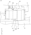
- FIG. 11 is a perspective view showing a schematic configuration of an engagement portion 255 of an insulator 51 according to the second embodiment.
- one of two coil winding bodies 21 adjacent to each other in the circumferential direction C is slid axially upward Y1.
- the insulator 51 of the coil winding body 21 has a tapered surface TA formed by chamfering the corners of the end face on the axially upper side (axially outer side) Y1 of the concave portion 55R and the end face on the axially lower side (axially inner side) Y2 of the convex portion 55P. Furthermore, the convex portion 55P is provided with a slit SL that is recessed circumferentially inward from the tip surface on the circumferential outer side of the convex portion 55P and penetrates therethrough in the axial direction.
- the structure other than the tapered surface TA and the slit SL is the same as that of the engaging portion 55 of the first embodiment.
- the tapered surface TA of the concave portion 55R and the tapered surface TA of the convex portion 55P act as an inducement during engagement, reducing the resistance force when the convex portion 55P is fitted into the concave portion 55R, and making it easier to position the engagement portion 255 when engaged. Furthermore, since the dimensional tolerance of the convex portion 55P is slightly larger than that of the concave portion 55R when engaged, the convex portion 55P bites into the concave portion 55R and deforms in the direction of opening the opening. However, by providing a slit in the convex portion 55P, the magnitude of distortion generated in the concave portion 55R can be reduced, and the fitting load when engaged is reduced.
- FIG. 12 is a perspective view showing a schematic configuration of an engagement portion 355 of an insulator 51 according to the present embodiment 2.
- one of two coil winding bodies 21 adjacent to each other in the circumferential direction C is slid axially upward Y1.
- the insulator 51 of the coil winding body 21 has an engagement portion 355 shaped such that the inner turned portion 355PI and the outer turned portion 355PO are provided on the axially lower side of the convex portion 55P of the insulator 51 of the coil winding body 21 as protrusions that protrude parallel to a first surface (not shown) perpendicular to the axial direction.
- the structure is the same as in embodiment 1.
- the opening of the concave portion 55R is deformed to open in the radial direction X by the width of the inner turned portion 355PI and the outer turned portion 355PO in the radial direction X during engagement, and the engagement is performed.
- the deformed concave portion 55R returns to its original shape, so that the axial upper surfaces of the inner turned portion 355PI and the outer turned portion 355PO protruding toward the first surface side come into contact with the axial lower surface of the concave portion 55R.
- the concave portion 55R and the convex portion 55P are caught in the axial direction Y by the inner turned portion 355PI and the outer turned portion 355PO, so that the convex portion 55P does not easily come off the concave portion 55R. This makes it less likely for the stator 20 to come loose due to an axial load when the completed workpiece is transported after manufacture, improving workability.
- the configuration is not limited to the inner turned portion 355PI and the outer turned portion 355PO opening the opening of the concave portion 55R in the radial direction X.
- the inner turned portion 355PI and the outer turned portion 355PO may be made of an elastic material and configured to be elastically deformed by pressure to reduce the protruding length, so that the opening of the concave portion 55R does not open in the radial direction X.
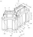
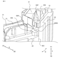
- FIG. 13 is a perspective view showing a state in which the coil winding bodies 21 according to the present embodiment 3 are connected to each other.
- the figure shows a state in which one of the two coil winding bodies 21 adjacent to each other in the circumferential direction C is slid upward in the axial direction Y1.
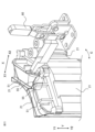
- FIG. 14 is an enlarged perspective view of an engagement portion 455 in a state in which the coil wound bodies 21 according to the third embodiment are connected to each other.
- FIG. 15 is a perspective view showing a state in which coil wound bodies 21 according to the third embodiment are connected to each other.
- the engaging portion 455 of the insulator 51 in this embodiment is formed so that the end face 55PS on the axially lower side (axially inner side) Y2 of the convex portion 55P is at the same position in the axial direction Y as the end face on the axially upper side (axially outer side) Y1 of the split core 22. Furthermore, the length H2 in the axial direction Y of the concave portion 55R of the engaging portion 455 is shorter than the length H1 in the axial direction Y of the convex portion 55P. Other than that, the structure is the same as that of the engaging portion 55 shown in the first embodiment.
- the end face 55PS of the axial lower side (axial inner side) Y2 of the convex portion 55P of the insulator 51 of one coil winding body 21 contacts the end face of the axial upper side Y1 (axial outer side) of the other split core 22.
- the convex portion 55P provided on one coil winding body 21 side straddles the axial end faces of the two adjacent split cores 22 and engages with the concave portion 55R of the other insulator 51.
- the axial end faces of the split cores 22 of the two adjacent coil winding bodies 21 are both in contact with the end face 55PS of the axial lower side Y2 of the convex portion 55P of one coil winding body 21.
- the axial end faces of the split cores 22 of the adjacent coil winding bodies 21 are aligned flush with each other.
- the end face 55PS of the axially lower side (axially inner side) Y2 of the convex portion 55P is at the same position in the axial direction Y as the end face of the axially upper side (axially outer side) Y1 of the split core 22, as long as the end face 55PS of the axially lower side Y2 of the convex portion 55P of at least one of the split cores 22 is abutted against the axial end face of an adjacent other split core 22, the axial end faces of the split cores 22 will be aligned.
- the length H2 in the axial direction Y of the concave portion 55R is shorter than the length H1 in the axial direction Y of the convex portion 55P, it is possible to suppress misalignment in the axial direction Y of the axial end faces of the connected split cores 22 caused by the misalignment between the axial length Y of the concave portion 55R and the axial length Y of the convex portion 55P.
- an axially inner end surface of the protrusion protruding circumferentially outward from the core side surface and an axial end surface of the split core are positioned at the same position in the axial direction,
- an axially inner end surface of the protrusion of one of the split cores is abutted against an axial end surface of the other split core that is adjacent to the circumferential direction, so that the axial end surfaces of the split cores are flush with each other in the axial direction.
- appendices An insulator that is attached to a split core having a back yoke portion extending in a circumferential direction and teeth protruding radially inward from the back yoke portion, and electrically insulates a wound coil from the split core, an engagement portion is formed on each of the axial end surfaces of the back yoke portion on both circumferential sides thereof to connect the split cores adjacent to each other in the circumferential direction, Each of the engaging portions of the insulators is configured to be engageable with the engaging portions of the other insulators adjacent thereto in the circumferential direction only from the axial direction side. Insulator.
- one of the engaging portions of each of the insulators has a convex portion that protrudes circumferentially outward beyond a core side surface of the split core adjacent in the circumferential direction, and the other of the engaging portions is provided circumferentially inward beyond the core side surface, and has a concave portion that is recessed circumferentially inward at the engaging portion and opens axially upward,
- the recess is formed so that the radial width at the circumferentially inner side is larger than the radial width at the opening, and the circumferentially outer tip portion of the protrusion is formed so that the radial side surface thereof is shaped to fit along the inner walls on both radial sides of the recess,
- a circumferential length from a boundary surface where the core side surfaces of the divided cores adjacent in the circumferential direction contact each other to a bottom surface of the recess is longer than a circumferential length from the boundary surface to a tip of the
- the insulator of claim 1 (Appendix 3) A gap is provided between the side surfaces of the insulators that face each other in the circumferential direction, and the recessed portion and the protruding portion are engaged with each other in the circumferential direction, and a tensile load of a set value or more is applied to the engaging portion. 3.
- the insulator according to claim 2. (Appendix 4) The tip surface of the protruding portion is recessed inward in the circumferential direction, and a slit penetrating in the axial direction is formed. 4. The insulator according to claim 2 or 3.
- At least one of the recessed portion and the protruding portion is The corners of the end faces in the axial direction are chamfered to form a tapered surface.
- An insulator according to any one of claims 2 to 4. (Appendix 6)
- the convex portion includes a protruding portion on an axially lower side, the protruding portion protruding in parallel with a first surface perpendicular to the axial direction,
- the protruding portion is configured to have a protruding length reduced by pressing, and when the protruding portion and the recessed portion are engaged with each other, the protruding portion protrudes in parallel to the first surface from an axially lower end face of the engaging portion having the engaged recessed portion, thereby restricting the protruding portion from coming out of the recessed portion in the axial direction.
- An insulator according to any one of claims 2 to 5. (Appendix 7) The recess is formed in a dovetail shape whose radial width gradually increases from the opening toward the circumferentially inner side, and the protrusion is formed in a dovetail shape whose radial width gradually increases toward the circumferentially outer side, the split cores adjacent in the circumferential direction are fixed in the radial direction by engagement between the recessed portions and the protruding portions of the engaging portions of the insulators adjacent in the circumferential direction.
- An insulator according to any one of claims 2 to 6. (Appendix 8) The insulators are provided at both ends of each of the split cores in the axial direction. 8. An insulator according to any one of claims 2 to 7.
- a stator for a rotating electric machine In a stator for a rotating electric machine, the coil is wound around the teeth portion of each of the split cores to which the insulator according to any one of Supplementary Note 1 to Supplementary Note 8 is attached, and the split cores are connected in an annular shape by the engaging portions, a frame or a molding resin is provided to cover the outer periphery of the split cores connected in an annular shape; A pressing force from a radially outer side to a radially inner side is applied to each of the divided cores by the frame or the molding resin.
- Stator of a rotating electric machine (Appendix 10) A stator of a rotating electric machine according to claim 9; A rotor arranged coaxially with the stator. Rotating electric motor.
- a method for manufacturing a stator for a rotating electric machine comprising: arranging the split cores, to which the insulator according to any one of Supplementary Note 2 to Supplementary Note 8 is attached, in an annular manner, and forming a core combination in which the split cores adjacent in a circumferential direction are connected by the engagement portions,
- the split cores constituting both ends of the core connected body are brought close to each other in the circumferential direction, and the split core having the convex portion at one end of the brought-close core connected body is slid axially upward so as to be positioned above the concave portion at the other end, and with the core side surfaces of the split cores constituting both ends of the core connected body in contact with each other, the convex portion is inserted into the concave portion from the axially upward side to engage the concave portion with the convex portion;
- a method for manufacturing a stator for a rotating electrical machine comprising: arranging the split cores, to which the insulator according to any one of Supplement
Landscapes
- Engineering & Computer Science (AREA)
- Power Engineering (AREA)
- Iron Core Of Rotating Electric Machines (AREA)
Priority Applications (1)
| Application Number | Priority Date | Filing Date | Title |
|---|---|---|---|
| JP2025526054A JPWO2024252962A1 (enExample) | 2023-06-05 | 2024-05-24 |
Applications Claiming Priority (2)
| Application Number | Priority Date | Filing Date | Title |
|---|---|---|---|
| JP2023-092030 | 2023-06-05 | ||
| JP2023092030 | 2023-06-05 |
Publications (1)
| Publication Number | Publication Date |
|---|---|
| WO2024252962A1 true WO2024252962A1 (ja) | 2024-12-12 |
Family
ID=93795869
Family Applications (1)
| Application Number | Title | Priority Date | Filing Date |
|---|---|---|---|
| PCT/JP2024/019263 Pending WO2024252962A1 (ja) | 2023-06-05 | 2024-05-24 | インシュレータ、回転電機のステータ、回転電機、および回転電機のステータの製造方法 |
Country Status (2)
| Country | Link |
|---|---|
| JP (1) | JPWO2024252962A1 (enExample) |
| WO (1) | WO2024252962A1 (enExample) |
Citations (7)
| Publication number | Priority date | Publication date | Assignee | Title |
|---|---|---|---|---|
| JP2011120473A (ja) * | 2004-03-23 | 2011-06-16 | Emerson Electric Co | セグメント化された固定子用端部キャップ |
| JP2015100166A (ja) * | 2013-11-18 | 2015-05-28 | アスモ株式会社 | 電機子コア |
| JP2015122939A (ja) * | 2013-11-25 | 2015-07-02 | アスモ株式会社 | 回転電機 |
| JP2016220490A (ja) * | 2015-05-26 | 2016-12-22 | 三菱電機株式会社 | 回転電機の固定子及び、回転電機の固定子の製造方法 |
| WO2020013280A1 (ja) * | 2018-07-12 | 2020-01-16 | 日本精工株式会社 | カップリング、トルク伝達装置、及び電動式パワーステアリング装置 |
| WO2021033496A1 (ja) * | 2019-08-20 | 2021-02-25 | 三菱電機株式会社 | ステータと回転電機、およびそれらの製造方法 |
| WO2022208965A1 (ja) * | 2021-03-29 | 2022-10-06 | 三菱電機株式会社 | 回転電機の固定子、回転電機、回転電機の固定子の製造方法および、回転電機の製造方法 |
-
2024
- 2024-05-24 JP JP2025526054A patent/JPWO2024252962A1/ja active Pending
- 2024-05-24 WO PCT/JP2024/019263 patent/WO2024252962A1/ja active Pending
Patent Citations (7)
| Publication number | Priority date | Publication date | Assignee | Title |
|---|---|---|---|---|
| JP2011120473A (ja) * | 2004-03-23 | 2011-06-16 | Emerson Electric Co | セグメント化された固定子用端部キャップ |
| JP2015100166A (ja) * | 2013-11-18 | 2015-05-28 | アスモ株式会社 | 電機子コア |
| JP2015122939A (ja) * | 2013-11-25 | 2015-07-02 | アスモ株式会社 | 回転電機 |
| JP2016220490A (ja) * | 2015-05-26 | 2016-12-22 | 三菱電機株式会社 | 回転電機の固定子及び、回転電機の固定子の製造方法 |
| WO2020013280A1 (ja) * | 2018-07-12 | 2020-01-16 | 日本精工株式会社 | カップリング、トルク伝達装置、及び電動式パワーステアリング装置 |
| WO2021033496A1 (ja) * | 2019-08-20 | 2021-02-25 | 三菱電機株式会社 | ステータと回転電機、およびそれらの製造方法 |
| WO2022208965A1 (ja) * | 2021-03-29 | 2022-10-06 | 三菱電機株式会社 | 回転電機の固定子、回転電機、回転電機の固定子の製造方法および、回転電機の製造方法 |
Also Published As
| Publication number | Publication date |
|---|---|
| JPWO2024252962A1 (enExample) | 2024-12-12 |
Similar Documents
| Publication | Publication Date | Title |
|---|---|---|
| JP5489698B2 (ja) | インシュレータ、回転電機および回転電機の製造方法 | |
| JP6461381B2 (ja) | 回転電機の固定子、回転電機、および、回転電機の固定子の製造方法 | |
| JP5418837B2 (ja) | 積層巻きコア及びこれを備えた回転子、回転電機 | |
| JPWO2016178368A1 (ja) | 回転電機およびその製造方法 | |
| JP2012143064A (ja) | 回転電機の固定子及びその製造方法 | |
| CN102104286A (zh) | 定子及设有该定子的电机 | |
| CN108702042A (zh) | 旋转电机和旋转电机的制造方法 | |
| WO2024252962A1 (ja) | インシュレータ、回転電機のステータ、回転電機、および回転電機のステータの製造方法 | |
| JP7188588B2 (ja) | ロータ、及び、ロータの製造方法 | |
| JP2020010553A (ja) | ステータコア | |
| JP6652308B2 (ja) | 電機子、回転電機および電機子の製造方法 | |
| JP7278398B2 (ja) | 回転電機 | |
| JP2008067527A (ja) | モータ及びモータの製造方法 | |
| KR101855834B1 (ko) | 분할코어를 구비한 전동기 | |
| JP7515363B2 (ja) | 回転電機およびその製造方法 | |
| JP7209480B2 (ja) | 回転電機および回転電機の製造方法 | |
| JP2011239626A (ja) | 回転電機 | |
| CN112544029B (zh) | 旋转电机 | |
| JP3671928B2 (ja) | 回転電機のアウターロータ構造 | |
| JP5130242B2 (ja) | ステータ | |
| JP2017046369A (ja) | 電機子、電機子の製造方法および回転電機 | |
| JP7723530B2 (ja) | インシュレータ、固定子、及びそれらを用いた回転電機 | |
| JP7203639B2 (ja) | 回転電機 | |
| JP2009268155A (ja) | 回転電機の固定子及び回転電機 | |
| JP2010154680A (ja) | 磁性ウェッジ並びにこれを用いたステータ及びその製造方法 |
Legal Events
| Date | Code | Title | Description |
|---|---|---|---|
| 121 | Ep: the epo has been informed by wipo that ep was designated in this application |
Ref document number: 24819194 Country of ref document: EP Kind code of ref document: A1 |
|
| WWE | Wipo information: entry into national phase |
Ref document number: 2025526054 Country of ref document: JP |