WO2024252962A1 - インシュレータ、回転電機のステータ、回転電機、および回転電機のステータの製造方法 - Google Patents
インシュレータ、回転電機のステータ、回転電機、および回転電機のステータの製造方法 Download PDFInfo
- Publication number
- WO2024252962A1 WO2024252962A1 PCT/JP2024/019263 JP2024019263W WO2024252962A1 WO 2024252962 A1 WO2024252962 A1 WO 2024252962A1 JP 2024019263 W JP2024019263 W JP 2024019263W WO 2024252962 A1 WO2024252962 A1 WO 2024252962A1
- Authority
- WO
- WIPO (PCT)
- Prior art keywords
- circumferential direction
- core
- stator
- insulator
- split
- Prior art date
- Legal status (The legal status is an assumption and is not a legal conclusion. Google has not performed a legal analysis and makes no representation as to the accuracy of the status listed.)
- Ceased
Links
Images



Classifications
-
- H—ELECTRICITY
- H02—GENERATION; CONVERSION OR DISTRIBUTION OF ELECTRIC POWER
- H02K—DYNAMO-ELECTRIC MACHINES
- H02K3/00—Details of windings
- H02K3/46—Fastening of windings on the stator or rotor structure
Definitions
- This disclosure relates to an insulator, a stator for a rotating electric machine, a rotating electric machine, and a method for manufacturing a stator for a rotating electric machine.
- each split core is combined with an insulator of a shape corresponding to its shape, and a coil is wound around the teeth of each split core via the insulator. Adjacent insulators are connected to each other by connecting parts formed on each insulator, and a rotating electrical machine stator equipped with an insulator of the following configuration has been devised.
- a first insulator member and a second insulator member each having a connecting rotation part at both circumferential ends, are combined with each split core, and the split core combined with the first insulator member and the split core combined with the second insulator member are arranged alternately in the circumferential direction.
- the connecting rotation parts at both circumferential ends of the first insulator have connecting protrusions that protrude in the axial direction
- the connecting rotation parts at both circumferential ends of the second insulator have connecting recesses that are recessed in the axial direction.
- the connecting recesses have openings that open radially outward.
- the connecting protrusion of the first insulator member is inserted into and engaged with the connecting recess of the second insulator member while being elastically deformed so as to widen the opening width of the connecting recess. Since the connecting recess of the second insulator member is elastically deformed so as to widen its opening width, the rigidity of the connecting portion against the load generated in the circumferential direction is low. Therefore, there is a problem that the split cores may be misaligned in the circumferential direction, which may increase the outer diameter of the stator or reduce its roundness.
- the present disclosure discloses techniques for solving the problems described above, and aims to provide an insulator that can suppress change in the outer diameter of a stator and ensure its roundness, a stator for a rotating electric machine in which change in the outer diameter is suppressed and roundness is ensured, a rotating electric machine in which high performance is ensured, and a method for manufacturing a stator for such a rotating electric machine.
- the insulator of the present disclosure comprises: An insulator that is attached to a split core having a back yoke portion extending in a circumferential direction and teeth protruding radially inward from the back yoke portion, and electrically insulates a wound coil from the split core, an engagement portion is formed on each of the axial end surfaces of the back yoke portion on both circumferential sides thereof to connect the split cores adjacent to each other in the circumferential direction, Each of the engaging portions of the insulators is configured to be engageable with the engaging portions of the other insulators adjacent thereto in the circumferential direction only from the axial direction side. It is something.
- the stator of the rotating electric machine includes: In a stator for a rotating electric machine, the coil is wound around the teeth of each of the split cores to which the insulator configured as described above is attached, and the split cores are connected in an annular shape by the engaging portions, a frame or a molding resin is provided to cover the outer periphery of the split cores connected in an annular shape; A pressing force from a radially outer side to a radially inner side is applied to each of the divided cores by the frame or the molding resin. It is something.
- the rotating electric machine of the present disclosure includes: a stator of a rotating electric machine configured as described above; A rotor arranged coaxially with the stator. It is something.
- a method for manufacturing a stator of a rotating electric machine includes the steps of: A method for manufacturing a stator for a rotating electric machine, comprising a connecting step of arranging the split cores, to which the insulators configured as described above are attached, in an annular shape, and connecting the split cores adjacent in a circumferential direction by the engaging portions to form a core connected body,
- the split cores constituting both ends of the core connected body are brought close to each other in the circumferential direction, and the split core having the convex portion at one end of the brought-close core connected body is slid axially upward so as to be positioned above the concave portion at the other end, and with the core side surfaces of the split cores constituting both ends of the core connected body in contact with each other, the convex portion is inserted into the concave portion from the axially upward side to engage the concave portion with the convex portion; It is something.
- the insulator and the stator for a rotating electric machine of the present disclosure it is possible to obtain an insulator and a stator for a rotating electric machine that can suppress changes in the outer diameter of the stator and ensure its roundness. Furthermore, according to the rotating electric machine and the method for manufacturing the stator of the rotating electric machine disclosed herein, high performance of the rotating electric machine can be ensured.
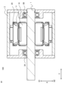
- FIG. 1 is a cross-sectional view showing an example of a schematic configuration of a rotating electric machine according to a first embodiment.
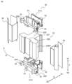
- 2 is an exploded perspective view showing a split core constituting a stator core of the stator according to the first embodiment and an insulating portion attached to the split core;
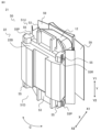
- FIG. 1 is a perspective view showing a coil winding body according to a first embodiment;
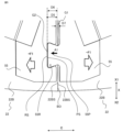
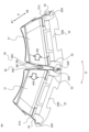
- 4 is an enlarged top view showing an engagement portion of the insulator according to the first embodiment.
- FIG. 4 is a top view showing a state in which the engaging portions of the insulator according to the first embodiment are engaged;
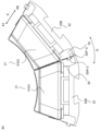
- FIG. 6A and 6B are diagrams illustrating the direction of a repulsive force that occurs when an insulating film is folded when the insulator according to the first embodiment is engaged.
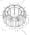
- FIG. 1 is a perspective view showing a state in which coil wound bodies according to embodiment 1 are connected to each other;
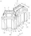
- FIG. 1 is an enlarged perspective view showing a state in which coil wound bodies according to the first embodiment are connected to each other;
- FIG. 13 is a top view showing another configuration of the engagement portion of the insulator according to embodiment 1.
- FIG. 4 is a cross-sectional view showing another configuration example of the rotating electric machine according to the first embodiment.
- FIG. FIG. 11 is a perspective view showing a schematic configuration of an engagement portion of an insulator according to a second embodiment.
- FIG. 11 is a perspective view showing a schematic configuration of an engagement portion of an insulator according to a second embodiment.
- 13 is a perspective view showing a state in which coil wound bodies according to embodiment 3 are connected to each other.
- FIG. 13 is an enlarged perspective view of an engagement portion when the coil wound bodies according to the third embodiment are connected to each other.
- FIG. 13 is a perspective view showing a state in which coil wound bodies according
- FIG. 1 is a cross-sectional view showing an example of a schematic configuration of a rotating electric machine 100 according to the first embodiment.
- the rotating electric machine 100 includes a rotor 10 fixed to a shaft 1 serving as a rotating shaft, and a stator 20 arranged concentrically with the rotor 10 and outside the rotor 10 in the radial direction X.
- the rotor 10 and the stator 20 are housed inside a hollow frame 2.
- the circumferential direction, radial direction, and axial direction of the rotating shaft of the annular stator 20 are respectively referred to as the circumferential direction C, the radial direction X, and the axial direction Y.
- the circumferential inner side of the yoke portion of the split core constituting the stator 20 refers to the central side of the yoke portion where the teeth are present.
- the circumferential outer side of the back yoke portion of the split core refers to the end side where the teeth are not present in the back yoke portion, or the direction circumferentially outer than this end.
- the axially upper side may be referred to as the axially outer side
- the axially lower side may be referred to as the axially inner side.
- the rotor 10 is equipped with a magnet 11 fixed inside the rotor 10.
- the shaft 1 to which the rotor 10 is fixed is rotatably supported by a first bearing 3A located on the output side of the shaft 1 and a second bearing 3B located on the opposite side to the output side, both of which are fixed within a frame 2.
- FIG. 2 is an exploded perspective view showing split cores 22 that constitute the stator core of stator 20 according to the first embodiment, and insulating parts 50 that are attached to split cores 22.
- the split cores 22 are obtained by dividing an annular stator core of an inner rotor type rotating electric machine 100 in the circumferential direction C by a set number of slots.
- the insulating portion 50 is attached to the split core 22 and electrically insulates the wound coil from the split core 22 .
- the split core 22 has a back yoke portion 22B extending in the circumferential direction C, and teeth portions 22T protruding radially inward X1 from an inner circumferential surface of a central portion in the circumferential direction C of the back yoke portion 22B.
- the core side surfaces 22BS of the opposing back yoke portions 22B have a planar shape along the radial direction X. Therefore, each split core 22 does not have the function of joining or holding the adjacent split cores 22 together.
- each split core 22 is configured in such a simple shape, it is only necessary to prepare one type of mold for the split cores 22, and manufacturing is easy.
- the insulating portion 50 is formed of an insulating material with a low elastic modulus, such as resin, and has a shape that fits the teeth portion 22T of the split core 22 so as to be fitted into the split core 22 for assembly.
- the insulating portion 50 comprises a first insulator 51U fitted to the axial upper side Y1 of the split core 22, a second insulator 51D fitted to the axial lower side Y2 of the split core 22, and an insulating film 59 covering both circumferential sides of the tooth portion 22T of the split core 22.
- the first insulator 51U and the second insulator 51D are the same parts having the same shape and function. However, when it is necessary to distinguish between the insulators 51 on the axial upper side Y1 and the axial lower side Y2 of the split core 22, they are referred to as the first insulator 51U and the second insulator 51D, and when there is no need to distinguish between them, they are referred to as the insulator 51.
- Each insulator 51 has a coil winding portion 52 , a back yoke covering portion 53 , and an engagement portion 55 .
- the coil winding portion 52 is arranged so as to overlap the tooth portion 22T of the split core 22 when viewed from the axial direction Y, and covers most of the end surface in the axial direction Y of the tooth portion 22T.
- the back yoke covering portion 53 covers most of the end face in the axial direction Y of the back yoke portion 22B.
- the engagement portions 55 are formed on both sides of the back yoke covering portion 53 in the circumferential direction C, and their detailed configuration will be described later, but they have a shape that can engage with the engagement portions 55 of other split cores 22 adjacent to them in the circumferential direction C.
- the insulating film 59 is attached along the circumferential C side of the teeth 22T of the split core 22, which forms the inner circumferential surface of the slot formed between adjacent teeth 22T in the circumferential C, the radial X inner surface of the back yoke portion 22B, and the radial X outer surface of the portion of the teeth 22T that protrudes circumferentially outward from the radial inner end.
- FIG. 3 is a perspective view showing a coil winding body 21 formed by winding the coil 12 via the insulating section 50 around the split core 22 to which the insulating section 50 constructed as described above is attached.
- the stator 20 of the present embodiment is configured by connecting a plurality of the coil winding bodies 21 in an annular shape.
- the back yoke covering portion 53 of the insulator 51 does not cover the radially outer side X2 of the back yoke portion 22B of the split core 22.
- the stator 20 formed in this manner is fixed to the inner peripheral surface of the frame 2 .
- the stator 20 is excited, and the rotor 10 disposed inside the stator 20 rotates.
- the rotating electrical machine 100 is not limited to an electric motor, but may be a generator.
- FIG. 4 is an enlarged top view showing the engaging portions 55 of the insulators 51 of the coil winding bodies 21 adjacent to each other in the circumferential direction C.
- the engaging portions 55 are not engaged with each other, that is, the coil winding bodies 21 are not connected to each other.
- FIG. 5 is a top view showing a state in which the engaging portions 55 of the insulators 51 of the coil winding bodies 21 adjacent to each other in the circumferential direction C are engaged with each other, and the coil winding bodies 21 are connected to each other.
- the back yoke covering portion 53 of the insulator 51 is provided with the engaging portions 55 at both ends in the circumferential direction C.
- the engaging portion 55 on one circumferential side of the insulator 51 is formed with a convex portion 55P as a convex portion that protrudes in a set shape toward the circumferential outside, and the engaging portion 55 on the other circumferential side is formed with a concave portion 55R as a recess that is recessed in a set shape toward the circumferential inside and penetrates in the axial direction Y. Therefore, as shown in FIG. 4, between the coil winding bodies 21 adjacent to each other in the circumferential direction C, the convex portion 55P and the concave portion 55R of the engagement portion 55 of the insulator 51 provided on each of the coil winding bodies 21 face each other.
- the concave portion 55R penetrates in the axial direction Y, and is therefore open on its axial upper side (axial outer side) Y1.
- This shape allows the insulators 51 adjacent to each other in the circumferential direction C to be engaged with each other from the axial direction Y. As will be described later, this shape also allows for an engagement state in which at least the split cores 22 are fixed to each other so as not to move away from each other in the circumferential direction C. In this manner, the first insulators 51U and the second insulators 51D are connected to each other by the engagement between the concave portions 55R and the convex portions 55P formed on each insulator.
- the configuration of the concave portions 55R and the convex portions 55P, and the connection structure of the insulators 51 formed by the engagement between the concave portions 55R and the convex portions 55P will be described below.
- the recessed portions 55R are formed so that the radial width D2 on the circumferentially inner side is larger than the radial width D1 at the opening.
- the radial side surface of the tip portion of the convex portion 55P is formed in a shape that follows the inner walls on both sides in the radial direction X of the concave portion 55R, and therefore the radial width D4 on the tip portion side in the radial direction X is formed to be larger than the radial width D3 on the circumferentially inner side.
- the concave portion 55R is formed to have a narrower opening than the inner side, with the minimum width D1 in the radial direction X located at the opening side and the maximum width D2 in the radial direction located at the inner side.
- the convex portion 55P is formed to have a narrower opening than the inner side, with the maximum width D4 located at the tip portion side and the minimum width D3 in the radial direction X located at the circumferentially inner root side.
- the width of the concave portion 55R in the radial direction X is designed to be equal to or slightly smaller than the width of the convex portion 55P in the radial direction X by a dimensional tolerance.
- the concave portion 55R is formed in a shape called a "dovetail shape” in which the opening is narrow and the width in the radial direction X gradually increases from the opening toward the circumferentially inward direction.
- the convex portion 55P is formed in a shape called a "dovetail shape” in which the width in the radial direction X gradually increases toward the circumferentially outward direction.
- the convex portion 55P having the above-mentioned shape protrudes circumferentially outward from the core side surface 22BS on the circumferential direction C side of the split core 22. Therefore, the convex portion 55P of the insulator 51 assembled to each split core 22 overlaps in the axial direction Y with at least a portion of the other split core 22 adjacent to that split core 22.
- the coil winding 21 on the convex portion 55P side is slid toward the axially upper side Y1 to bring the core side surfaces 22BS of the adjacent split cores 22 into contact with each other, while the convex portion 55P is inserted from above the concave portion 55R to engage them.
- the width in the radial direction X of the concave portion 55R is formed to be the same as or slightly smaller than the width in the radial direction X of the convex portion 55P. Therefore, the convex portion 55P is lightly pressed into the concave portion 55R while slightly expanding the concave portion 55R in the radial direction X.
- This state in which the convex portion 55P is fitted into the concave portion 55R is the state in which the concave portion 55R and the convex portion 55P are engaged (hereinafter, sometimes simply referred to as the "engaged state").
- the concave portion 55R is formed at a position that substantially overlaps with the opposing convex portion 55P in the axial direction Y.
- the concave portion 55R and the convex portion 55P are positioned so as to almost overlap in the axial direction Y, more specifically, when the core side surfaces 22BS are in contact with each other, the concave portion 55R is shifted in the circumferential direction C relative to the convex portion 55P in a direction away from the boundary surface BO where the core side surfaces 22BS are in contact with each other.
- the length D5 in the circumferential direction C from the boundary surface BO to the bottom surface of the concave-shaped portion 55R is longer than the length D6 in the circumferential direction C from the boundary surface BO to the circumferentially outermost tip of the convex-shaped portion 55P. Therefore, in order to insert the tip portion of the convex portion 55P, which is formed to have the same shape as the inner wall of the concave portion 55R, into the concave portion 55R, the convex portion 55P is pulled in the direction of arrow A1 in Figure 5 beyond the boundary surface BO and then inserted into the concave portion 55R.
- each insulator 51 is formed so that a gap G1 having a set width D7 in the circumferential direction C is secured between the side surfaces of adjacent insulators 51. Therefore, when the concave portion 55R and the convex portion 55P are engaged, a tensile load F1 (+F1, -F1) in the circumferential direction C is generated in the engagement portion 55 such that the concave portion 55R is pulled toward the convex portion 55P (load -F1) and the convex portion 55P is pulled toward the concave portion 55R (load +F1).
- a preload is generated in a direction that maintains the tight contact between the core side surfaces 22BS, which are the mating surfaces of the split cores 22.
- the core side surfaces 22BS which are the mating surfaces of the split cores 22.
- the outer gradient portion PX2 on the radially outer side X2 of the convex portion 55P and the inner gradient portion PX1 on the radially inner side X1 of the convex portion 55P are in surface-to-surface contact with the outer gradient portion RX2 on the radially outer side X2 of the concave portion 55R and the inner gradient portion RX1 on the radially inner side X1 of the concave portion 55R.
- the gradient portions of the convex portion 55P and the concave portion 55R are in constant contact with each other, making it possible to fix the convex portion 55P in the radial direction X as well as in the circumferential direction C.
- the bottom surface RS of the concave portion 55R and the tip surface PS of the convex portion 55P do not make contact when engaged.
- the concave portion 55R is formed so that when engaged, it is displaced away from the convex portion 55P in the circumferential direction C, and a tensile load is applied that pulls them together, creating a gap G2 between the bottom surface RS of the concave portion 55R and the tip surface PS of the convex portion 55P.
- FIG. 6 is a diagram showing the direction of the repulsive force that occurs when the insulating film 59 is folded when the insulator 51 of this embodiment is engaged.
- the insulating film 59 is composed of an outer film 59O and an inner film 59I. 6, the outer film 59O is folded so as to overlap the inner film 59I.
- a gap G2 is created between the bottom surface RS of the concave portion 55R and the tip surface PS of the convex portion 55P so that the tensile load F1 is greater than the load F2, which is the repulsive force that pushes back in the circumferential direction when the insulating films 59 attached to adjacent split cores 22 come into contact with each other.
- the length D5 in the circumferential direction C from the boundary surface BO to the bottom surface of the concave portion 55R and the length D6 in the circumferential direction C from the boundary surface BO to the tip surface of the convex portion 55P at the outermost side in the circumferential direction are adjusted so that the tensile load F1 is greater than the repulsive force F2.
- the dimensions are designed so that the maximum strain generated in the engaging portion 55 does not exceed the breaking strain when subjected to a load caused by light press-fitting when the convex portion 55P is inserted into the concave portion 55R, and a circumferential tensile load that pulls the convex portion 55P toward the concave portion 55R.
- the outer gradient portion PX2 and the inner gradient portion PX1 of the convex portion 55P are in contact with the surfaces of the outer gradient portion RX2 and the inner gradient portion RX1 of the concave portion 55R.
- the convex portion 55P is sandwiched between the outer gradient portion RX2 and the inner gradient portion RX1 of the concave portion 55R. This results in the convex portion 55P being held in a state in which it is enveloped within the concave portion 55R, which has a narrow opening.
- the axial upper side Y1 of the stator 20 is formed by connecting the first insulators 51U to each other, and the axial lower side Y2 of the stator 20 is formed by connecting the second insulators 51D to each other.
- the first insulators 51U and the second insulators 51D have exactly the same shape.
- the concave portion 55R and the convex portion 55P are located at diagonal corners of the split core 22 when the split core 22 is viewed from the radially outer side X2.
- the connection structure in the axial direction Y between the split core 22 and the adjacent split core 22 is different between one circumferential side and the other circumferential side of the back yoke portion 22B.
- the first insulator 51U and the second insulator 51D have been described as having the same shape, but even if the first insulator 51U and the second insulator 51D have different shapes, it is possible to position the concave portion 55R and the convex portion 55P at diagonal corners of the split core 22.
- FIG. 7 is a perspective view showing a state in which coil wound bodies 21 according to the first embodiment are connected to each other.
- FIG. 8 is an enlarged perspective view showing a state in which coil wound bodies 21 according to the first embodiment are connected to each other.
- the stator 20 of the present embodiment is configured with nine coil winding bodies 21 (split cores 22), but is not limited to this number.
- the nine coil winding bodies 21 may be referred to as the first coil winding body 21 through the ninth coil winding body 21 to distinguish them from one another. Also, in the figures, the positions corresponding to the first coil winding body 21 through the ninth coil winding body 21 are numbered No. 1 through No. 9.
- a winding body forming process is performed in which the insulating portion 50 is attached to the split core 22, and then the coil 12 is wound around the split core 22 to form nine coil winding bodies 21.
- a connecting step is performed in which the nine formed coil winding bodies 21 are arranged in an annular shape, and adjacent split cores 22 in the circumferential direction C are connected by their respective engaging portions 55 to form a core connected body 30 .
- the core connected body 30 shown in FIG. 7 is one in which all of the engaging portions 55 are engaged with each other, except for one engagement between the first coil winding body 21 (No. 1) and the ninth coil winding body 21 (No. 9).
- the coil winding body 21 is moved from a state in which the core side surfaces 22BS of the split cores 22 of the already engaged coil winding body 21 are in contact to an engagement position in which the coils 12 of the coil winding body 21 are slightly spaced apart. Then, as shown in FIG. 7, the space between the first coil winding body 21 (No. 1) and the ninth coil winding body 21 (No. 9) is opened in the circumferential direction C.
- the split core 22 of the first coil winding body 21 (No. 1) constituting one end side of the core connection body 30 and the split core 22 of the first coil winding body 21 (No. 9) constituting the other end side are brought into close proximity in the circumferential direction C.
- the split core 22 of the first coil winding body 21 (No. 1) having a convex portion 55P on one end side of the core connecting body 30 is slid axially upward Y1 while maintaining the engagement between the split core 22 of this first coil winding body 21 (No. 1) and the second coil winding body 21 (No.
- the core side surfaces 22BS of the split cores 22 of the first coil winding body 21 and the ninth coil winding body 21 are brought into contact with each other.
- the first coil winding body 21 (No. 1) is slid axially downward Y2, and the convex portion 55P of the first coil winding body 21 is inserted axially into the concave portion 55R of the ninth coil winding body 21 (No. 9).
- the tip side of the convex portion 55P of the first coil winding body 21 (No. 1) is pulled in the circumferential direction C from the boundary surface BO toward the concave portion 55R, while the convex portion 55P is inserted into the concave portion 55R from the axial direction Y.
- the convex portion 55P of the first coil winding body 21 (No. 1) and the concave portion 55R of the ninth coil winding body 21 (No. 9) are engaged, and the stator 20 is completed.
- a torsional load is generated in each convex portion 55P and each concave portion 55R in the stator 20, but the dimensions are designed so that the maximum strain generated in the engagement portion 55 does not exceed the fracture strain.
- a dedicated jig that can reproduce the manufacturing method described above may be used as a means of engagement. When using a jig, material and design costs are incurred, but workability can be improved.
- the completed stator 20 is press-fitted or shrink-fitted into a cylindrical frame 2 as shown in FIG. 1.
- the frame 2 may be a steel plate frame or may be integrally molded from resin, and the stator 20 is compatible with frames of all configurations.
- first bearing 3A and the second bearing 3B are press-fitted or shrink-fitted onto the shaft 1.
- the rotor 10 is inserted into the frame 2 in which the stator 20 is mounted.
- the bracket is inserted and the first bearing 3A and the second bearing 3B are fixed, and the rotating electric machine 100 is completed.
- the engaging portion of the insulator 51 is located radially inward X1 from the outer periphery of the split core 22, it can be press-fitted or shrink-fitted into the simple cylindrical frame 2, allowing for a simple assembly method to be selected. Since the frame 2 holds the stator 20 core, the connecting force of the insulator 51 is sufficient if it can withstand transportation up to the shrink-fitting process. In addition, the preload created by the interference of the press fit and shrink fit ensures that the core side surfaces 22BS, which are the mating surfaces of the split cores 22, come into even contact with each other, thereby ensuring the roundness of the inner circumferential surface of the radially inner portion of the stator 20.
- the workability of the ring assembly is improved by using the insulators 51 of the same shape on the top and bottom and engaging them in the axial direction Y, while the engaging portions 55 are engaged with each other without being inserted or removed in the circumferential direction C, so that the expansion of the outer diameter of the stator 20 due to the load generated in the circumferential direction C can be restricted, improving the workability of the frame shrink fitting.
- FIG. 9 is a top view showing the configuration of the engagement portion 55 of the insulator 51EX according to the first embodiment.
- the convex portion 55P-2 and the concave portion 55R-2 of the engagement portion 55 of the insulator 51EX in this embodiment 1 do not have the outer slope portions PX2, RX2 and the inner slope portions PX1, RX1 as shown in Figure 4 on both sides in the radial direction X.
- the convex portion 55P-2 and the concave portion 55R-2 have surfaces parallel to the boundary surface BO, which is the contact surface between the core side surfaces 22BS parallel to the radial direction X, and the surfaces of the convex portion 55P-2 and the concave portion 55R-2 that face each other in the circumferential direction C are in contact with each other.
- the surfaces of the convex portion 55P-2 that are parallel to the core side surfaces 22BS and the surfaces of the concave portion 55R that are parallel to the core side surfaces 22BS are in contact with each other. Therefore, they are not fixed in a direction parallel to the contact surface between the core side surfaces 22BS that are parallel to the radial direction X, but are fixed only in the circumferential direction C.
- adjacent coil winding bodies 21 are not fixed in a direction parallel to the contact surfaces between the core side surfaces 22BS, i.e., in the radial direction X, but are fixed so as not to shift in position in the circumferential direction C, thereby preventing the outer diameter of the stator 20 from expanding significantly. Furthermore, by configuring the positional relationship between the convex portion 55P-2 and the concave portion 55R-2 so that a set tensile load F1 is applied to the engagement portion 55, the core side surfaces 22BS of the split cores 22 are firmly attached to each other, thereby suppressing misalignment in the radial direction X. According to this configuration, the dimensional design of the convex portion 55P-2 and the concave portion 55R-2 can be simplified, improving productivity.
- the shapes of the convex and concave portions are not limited to those shown above.
- the concave portion is formed so that the radial width at the circumferentially inner side is larger than the radial width at the opening, and the circumferentially outer tip portion of the convex portion has a side surface on the radial side that conforms to the inner walls on both radial sides of the concave portion. Therefore, the concave portion may have a circular inner peripheral surface, and the convex portion may have a circular tip side that fits into the concave portion. It is sufficient that the convex portion cannot be inserted from the direction of a first surface (not shown) perpendicular to the axial direction Y, and at least adjacent split cores are fixed in the circumferential direction C.
- FIG. 10 is a cross-sectional view showing a schematic configuration of a rotating electric machine 100A according to the first embodiment.
- the rotating electric machine 100 shown in Fig. 1 has a configuration in which the outer periphery of the stator 20 is covered with a frame 2 and fastened from the outer periphery side to further bring the core side surfaces 22BS of each split core 22 into close contact with each other.
- the present invention is not limited to this configuration, and a structure in which the outer periphery of the stator 20 assembled into a ring is molded with resin 4 as shown in Fig. 10 may be used.
- the connecting force between the insulators 51 is sufficient if it can withstand transportation to the molding process. This allows the stator 20 core to be forced into the mold by the molding pressure of the resin, ensuring precision of the inner diameter of the stator 20 .
- An insulator that is attached to a split core having a back yoke portion extending in a circumferential direction and teeth protruding radially inward from the back yoke portion, and electrically insulates a wound coil from the split core, an engagement portion is formed on each of the axial end surfaces of the back yoke portion on both circumferential sides thereof to connect the split cores adjacent to each other in the circumferential direction,
- Each of the engaging portions of the insulators is configured to be engageable with the engaging portions of the other insulators adjacent thereto in the circumferential direction only from the axial direction side. It is something.
- the engaging parts are not shaped to be removable from each other in the circumferential direction, but can only be engaged from the axial direction. Therefore, the load direction when engaging the engaging parts is different from the load direction generated on the engaging parts when engaged, that is, the axial direction and the circumferential direction. This makes it possible to prevent the engaging parts from being disengaged during the manufacturing process, and to prevent the connected insulators from being separated. It also makes it possible to suppress changes in the outer diameter of the stator and deterioration of its roundness, which would otherwise be caused by the split cores being displaced from each other in the circumferential direction.
- one of the engaging portions of each of the insulators has a convex portion that protrudes circumferentially outward beyond a core side surface of the split core adjacent in the circumferential direction, and the other of the engaging portions is provided circumferentially inward beyond the core side surface, and has a concave portion that is recessed circumferentially inward at the engaging portion and opens axially upward,
- the recess is formed so that the radial width at the circumferentially inner side is larger than the radial width at the opening, and the circumferentially outer tip portion of the protrusion is formed so that the radial side surface thereof is shaped to fit along the inner walls on both radial sides of the recess,
- a circumferential length from a boundary surface where the core side surfaces of the divided cores adjacent in the circumferential direction contact each other to a bottom surface of the recess is longer than a circumferential length from the boundary surface to
- one of the engaging portions of each insulator has a convex portion that protrudes circumferentially outward, and the other has a concave portion that is recessed circumferentially inward and opens axially upward (axially outward). Therefore, when these insulators are lined up in the circumferential direction, the convex portion and concave portion of each insulator face each other. This makes it possible to connect the split cores using one type of insulator with the same shape, thereby reducing costs and simplifying the work.
- the recess is open axially upward (axially outward), and is formed so that the radial width at the circumferentially inner side is greater than the radial width at the opening.
- the side of the tip of the protrusion is formed in a shape that follows the inner walls on both radial sides of the recess, i.e., the protrusion is formed to have approximately the same shape as the recess. In this way, the protrusion and recess of the engagement part can only engage from the axially upward side (axially outward), which reliably prevents the insulators from separating from each other.
- the convex portion is provided so as to protrude circumferentially outward from the core side surface, and the concave portion is provided circumferentially inward from the core side surface.
- the circumferential length from a boundary surface BO, where the core side surfaces of the split cores adjacent in the circumferential direction come into contact, to the bottom surface of the concave portion is configured to be longer than the circumferential length from the boundary surface BO to the tip of the convex portion.
- the protrusion is pulled toward the recess from the boundary surface BO and inserted into the recess while applying a tensile load in the circumferential direction.
- This circumferential load applied to the protrusion and recess generates a preload in a direction that maintains the close contact between the core side surfaces of the split cores. This realizes a strong connection between adjacent split cores. This makes it possible to further suppress changes in the outer diameter of the stator and deterioration of its roundness.
- the tip surface of the protrusion does not completely match the shape of the bottom surface of the recess, as long as at least the radial side surface of the protrusion is formed in a shape that fits along the inner walls of the recess on both radial sides, it can engage with the recess when a circumferential load is applied. This makes it possible to absorb dimensional variations due to molding errors in the engaging portion when the insulator is formed.
- a gap is provided between the side surfaces of the insulators that face each other in the circumferential direction, and the recessed portion and the protruding portion are engaged with each other in the circumferential direction, and a tensile load of a set value or more is applied to the engaging portion. It is something.
- FIG. 11 is a perspective view showing a schematic configuration of an engagement portion 255 of an insulator 51 according to the second embodiment.
- one of two coil winding bodies 21 adjacent to each other in the circumferential direction C is slid axially upward Y1.
- the insulator 51 of the coil winding body 21 has a tapered surface TA formed by chamfering the corners of the end face on the axially upper side (axially outer side) Y1 of the concave portion 55R and the end face on the axially lower side (axially inner side) Y2 of the convex portion 55P. Furthermore, the convex portion 55P is provided with a slit SL that is recessed circumferentially inward from the tip surface on the circumferential outer side of the convex portion 55P and penetrates therethrough in the axial direction.
- the structure other than the tapered surface TA and the slit SL is the same as that of the engaging portion 55 of the first embodiment.
- the tapered surface TA of the concave portion 55R and the tapered surface TA of the convex portion 55P act as an inducement during engagement, reducing the resistance force when the convex portion 55P is fitted into the concave portion 55R, and making it easier to position the engagement portion 255 when engaged. Furthermore, since the dimensional tolerance of the convex portion 55P is slightly larger than that of the concave portion 55R when engaged, the convex portion 55P bites into the concave portion 55R and deforms in the direction of opening the opening. However, by providing a slit in the convex portion 55P, the magnitude of distortion generated in the concave portion 55R can be reduced, and the fitting load when engaged is reduced.
- FIG. 12 is a perspective view showing a schematic configuration of an engagement portion 355 of an insulator 51 according to the present embodiment 2.
- one of two coil winding bodies 21 adjacent to each other in the circumferential direction C is slid axially upward Y1.
- the insulator 51 of the coil winding body 21 has an engagement portion 355 shaped such that the inner turned portion 355PI and the outer turned portion 355PO are provided on the axially lower side of the convex portion 55P of the insulator 51 of the coil winding body 21 as protrusions that protrude parallel to a first surface (not shown) perpendicular to the axial direction.
- the structure is the same as in embodiment 1.
- the opening of the concave portion 55R is deformed to open in the radial direction X by the width of the inner turned portion 355PI and the outer turned portion 355PO in the radial direction X during engagement, and the engagement is performed.
- the deformed concave portion 55R returns to its original shape, so that the axial upper surfaces of the inner turned portion 355PI and the outer turned portion 355PO protruding toward the first surface side come into contact with the axial lower surface of the concave portion 55R.
- the concave portion 55R and the convex portion 55P are caught in the axial direction Y by the inner turned portion 355PI and the outer turned portion 355PO, so that the convex portion 55P does not easily come off the concave portion 55R. This makes it less likely for the stator 20 to come loose due to an axial load when the completed workpiece is transported after manufacture, improving workability.
- the configuration is not limited to the inner turned portion 355PI and the outer turned portion 355PO opening the opening of the concave portion 55R in the radial direction X.
- the inner turned portion 355PI and the outer turned portion 355PO may be made of an elastic material and configured to be elastically deformed by pressure to reduce the protruding length, so that the opening of the concave portion 55R does not open in the radial direction X.
- FIG. 13 is a perspective view showing a state in which the coil winding bodies 21 according to the present embodiment 3 are connected to each other.
- the figure shows a state in which one of the two coil winding bodies 21 adjacent to each other in the circumferential direction C is slid upward in the axial direction Y1.
- FIG. 14 is an enlarged perspective view of an engagement portion 455 in a state in which the coil wound bodies 21 according to the third embodiment are connected to each other.
- FIG. 15 is a perspective view showing a state in which coil wound bodies 21 according to the third embodiment are connected to each other.
- the engaging portion 455 of the insulator 51 in this embodiment is formed so that the end face 55PS on the axially lower side (axially inner side) Y2 of the convex portion 55P is at the same position in the axial direction Y as the end face on the axially upper side (axially outer side) Y1 of the split core 22. Furthermore, the length H2 in the axial direction Y of the concave portion 55R of the engaging portion 455 is shorter than the length H1 in the axial direction Y of the convex portion 55P. Other than that, the structure is the same as that of the engaging portion 55 shown in the first embodiment.
- the end face 55PS of the axial lower side (axial inner side) Y2 of the convex portion 55P of the insulator 51 of one coil winding body 21 contacts the end face of the axial upper side Y1 (axial outer side) of the other split core 22.
- the convex portion 55P provided on one coil winding body 21 side straddles the axial end faces of the two adjacent split cores 22 and engages with the concave portion 55R of the other insulator 51.
- the axial end faces of the split cores 22 of the two adjacent coil winding bodies 21 are both in contact with the end face 55PS of the axial lower side Y2 of the convex portion 55P of one coil winding body 21.
- the axial end faces of the split cores 22 of the adjacent coil winding bodies 21 are aligned flush with each other.
- the end face 55PS of the axially lower side (axially inner side) Y2 of the convex portion 55P is at the same position in the axial direction Y as the end face of the axially upper side (axially outer side) Y1 of the split core 22, as long as the end face 55PS of the axially lower side Y2 of the convex portion 55P of at least one of the split cores 22 is abutted against the axial end face of an adjacent other split core 22, the axial end faces of the split cores 22 will be aligned.
- the length H2 in the axial direction Y of the concave portion 55R is shorter than the length H1 in the axial direction Y of the convex portion 55P, it is possible to suppress misalignment in the axial direction Y of the axial end faces of the connected split cores 22 caused by the misalignment between the axial length Y of the concave portion 55R and the axial length Y of the convex portion 55P.
- an axially inner end surface of the protrusion protruding circumferentially outward from the core side surface and an axial end surface of the split core are positioned at the same position in the axial direction,
- an axially inner end surface of the protrusion of one of the split cores is abutted against an axial end surface of the other split core that is adjacent to the circumferential direction, so that the axial end surfaces of the split cores are flush with each other in the axial direction.
- appendices An insulator that is attached to a split core having a back yoke portion extending in a circumferential direction and teeth protruding radially inward from the back yoke portion, and electrically insulates a wound coil from the split core, an engagement portion is formed on each of the axial end surfaces of the back yoke portion on both circumferential sides thereof to connect the split cores adjacent to each other in the circumferential direction, Each of the engaging portions of the insulators is configured to be engageable with the engaging portions of the other insulators adjacent thereto in the circumferential direction only from the axial direction side. Insulator.
- one of the engaging portions of each of the insulators has a convex portion that protrudes circumferentially outward beyond a core side surface of the split core adjacent in the circumferential direction, and the other of the engaging portions is provided circumferentially inward beyond the core side surface, and has a concave portion that is recessed circumferentially inward at the engaging portion and opens axially upward,
- the recess is formed so that the radial width at the circumferentially inner side is larger than the radial width at the opening, and the circumferentially outer tip portion of the protrusion is formed so that the radial side surface thereof is shaped to fit along the inner walls on both radial sides of the recess,
- a circumferential length from a boundary surface where the core side surfaces of the divided cores adjacent in the circumferential direction contact each other to a bottom surface of the recess is longer than a circumferential length from the boundary surface to a tip of the
- the insulator of claim 1 (Appendix 3) A gap is provided between the side surfaces of the insulators that face each other in the circumferential direction, and the recessed portion and the protruding portion are engaged with each other in the circumferential direction, and a tensile load of a set value or more is applied to the engaging portion. 3.
- the insulator according to claim 2. (Appendix 4) The tip surface of the protruding portion is recessed inward in the circumferential direction, and a slit penetrating in the axial direction is formed. 4. The insulator according to claim 2 or 3.
- At least one of the recessed portion and the protruding portion is The corners of the end faces in the axial direction are chamfered to form a tapered surface.
- An insulator according to any one of claims 2 to 4. (Appendix 6)
- the convex portion includes a protruding portion on an axially lower side, the protruding portion protruding in parallel with a first surface perpendicular to the axial direction,
- the protruding portion is configured to have a protruding length reduced by pressing, and when the protruding portion and the recessed portion are engaged with each other, the protruding portion protrudes in parallel to the first surface from an axially lower end face of the engaging portion having the engaged recessed portion, thereby restricting the protruding portion from coming out of the recessed portion in the axial direction.
- An insulator according to any one of claims 2 to 5. (Appendix 7) The recess is formed in a dovetail shape whose radial width gradually increases from the opening toward the circumferentially inner side, and the protrusion is formed in a dovetail shape whose radial width gradually increases toward the circumferentially outer side, the split cores adjacent in the circumferential direction are fixed in the radial direction by engagement between the recessed portions and the protruding portions of the engaging portions of the insulators adjacent in the circumferential direction.
- An insulator according to any one of claims 2 to 6. (Appendix 8) The insulators are provided at both ends of each of the split cores in the axial direction. 8. An insulator according to any one of claims 2 to 7.
- a stator for a rotating electric machine In a stator for a rotating electric machine, the coil is wound around the teeth portion of each of the split cores to which the insulator according to any one of Supplementary Note 1 to Supplementary Note 8 is attached, and the split cores are connected in an annular shape by the engaging portions, a frame or a molding resin is provided to cover the outer periphery of the split cores connected in an annular shape; A pressing force from a radially outer side to a radially inner side is applied to each of the divided cores by the frame or the molding resin.
- Stator of a rotating electric machine (Appendix 10) A stator of a rotating electric machine according to claim 9; A rotor arranged coaxially with the stator. Rotating electric motor.
- a method for manufacturing a stator for a rotating electric machine comprising: arranging the split cores, to which the insulator according to any one of Supplementary Note 2 to Supplementary Note 8 is attached, in an annular manner, and forming a core combination in which the split cores adjacent in a circumferential direction are connected by the engagement portions,
- the split cores constituting both ends of the core connected body are brought close to each other in the circumferential direction, and the split core having the convex portion at one end of the brought-close core connected body is slid axially upward so as to be positioned above the concave portion at the other end, and with the core side surfaces of the split cores constituting both ends of the core connected body in contact with each other, the convex portion is inserted into the concave portion from the axially upward side to engage the concave portion with the convex portion;
- a method for manufacturing a stator for a rotating electrical machine comprising: arranging the split cores, to which the insulator according to any one of Supplement
Landscapes
- Engineering & Computer Science (AREA)
- Power Engineering (AREA)
- Iron Core Of Rotating Electric Machines (AREA)
Abstract
周方向に延在するバックヨーク部(22B)と前記バックヨーク部(22B)から径方向内側に突出するティース部(22T)とを有する分割コア(22)に装着され、巻装されるコイル(12)と前記分割コア(22)とを電気的に絶縁するインシュレータ(51)であって、前記バックヨーク部(22B)の軸方向端面上の周方向両側において、周方向に隣り合う前記分割コア同士(22)を接続する係合部(55)がそれぞれ形成され、各前記インシュレータ(51)の各前記係合部(55)は、周方向に隣り合う他の前記インシュレータ(51)の前記係合部(55)と、軸方向側からのみ係合可能に構成される。
Description
本開示は、インシュレータ、回転電機のステータ、回転電機、および回転電機のステータの製造方法に関するものである。
回転電機の固定子(ステータ)において、コイルの占積率向上のため、ステータコアをティース部毎に周方向に分割する分割コア構造がある。各分割コアには、その形状に対応した形状のインシュレータが組合されるとともに、各分割コアのティース部には、インシュレータを介してコイルが巻回されている。そして、隣り合うインシュレータ同士を、各インシュレータに形成された連結部で連結する、以下のような構成のインシュレータを備えた回転電機のステータが考案されている。
即ち、従来の回転電機のステータにおいては、それぞれ周方向両端に連結回動部を有する第1インシュレータ部材と第2インシュレータ部材とが各分割コアに組合され、第1インシュレータ部材が組合された分割コアと、第2インシュレータ部材が組合された分割コアと、が周方向に交互に配置される。第1インシュレータの周方向両端の連結回動部は軸方向に突出する連結凸部を有し、第2インシュレータの周方向両端の連結回動部は軸方向に窪む連結凹部を有している。連結凹部は、径方向外側に開口する開口部を有している。周方向に隣接する分割コアにおいて、第2インシュレータ部材の連結凹部に対して第1インシュレータ部材の連結凸部を径方向外側から押圧すると、連結凹部の周方向の開口幅が広がり連結凸部が連結凹部内に進入し、第1、第2インシュレータ部材が連結され、周方向に隣接する分割コアが接続される(例えば、特許文献1参照)。
しかしながら、上記従来の回転電機のステータの各分割コアに組合されるインシュレータ部材では、第1インシュレータ部材の連結凸部を、第2インシュレータ部材の連結凹部の開口幅が広がるように弾性変形させながらこの連結凹部に挿入して係合させる。このように第2インシュレータ部材の連結凹部はその開口幅が広がるように弾性変形するため、周方向に発生する荷重に対しての連結部分の剛性が小さい。そのため、分割コア同士が周方向に離れるようにずれ、ステータの外径が大きくなったり、その真円度が低下したりする場合があるという課題があった。
また、ステータの真円度が低下すると、このステータを用いた回転電機においてノイズが増加し、性能が悪化するという課題があった。
本開示は、上記のような課題を解決するための技術を開示するものであり、ステータの外径変化を抑制して、その真円度を確保できるインシュレータ、外径変化が抑制され、真円度が確保された回転電機のステータ、高い性能が確保された回転電機、およびその回転電機のステータの製造方法を提供することを目的とする。
また、ステータの真円度が低下すると、このステータを用いた回転電機においてノイズが増加し、性能が悪化するという課題があった。
本開示は、上記のような課題を解決するための技術を開示するものであり、ステータの外径変化を抑制して、その真円度を確保できるインシュレータ、外径変化が抑制され、真円度が確保された回転電機のステータ、高い性能が確保された回転電機、およびその回転電機のステータの製造方法を提供することを目的とする。
本開示のインシュレータは、
周方向に延在するバックヨーク部と前記バックヨーク部から径方向内側に突出するティース部とを有する分割コアに装着され、巻装されるコイルと前記分割コアとを電気的に絶縁するインシュレータであって、
前記バックヨーク部の軸方向端面上の周方向両側において、周方向に隣り合う前記分割コア同士を接続する係合部がそれぞれ形成され、
各前記インシュレータの各前記係合部は、周方向に隣り合う他の前記インシュレータの前記係合部と、軸方向側からのみ係合可能に構成される、
ものである。
また、本開示の回転電機のステータは、
上記のように構成されたインシュレータが装着された各前記分割コアの前記ティース部に前記コイルが巻装され、各前記分割コアを各前記係合部により環状に連結して構成された回転電機のステータにおいて、
環状に連結された前記分割コアの外周を覆うフレームあるいはモールド樹脂が配設され、
前記フレームあるいは前記モールド樹脂により、径方向外側から径方向内側への押圧力が各前記分割コアに付与される、
ものである。
また、本開示の回転電機は、
上記のように構成された回転電機のステータと、
前記ステータと同軸上に配置されたロータと、を備える、
ものである。
また、本開示の回転電機のステータの製造方法は、
上記のように構成されたインシュレータを装着した前記分割コアを環状に配列して、周方向に隣り合う前記分割コアを前記係合部により接続したコア連結体を形成する連結工程を有する回転電機のステータの製造方法であって、
前記連結工程において、
前記コア連結体の両端側をそれぞれ構成する前記分割コア同士を周方向に近接させ、近接された前記コア連結体の一方の端部側に前記凸部を有する前記分割コアを、他方の端部側の前記凹部の上方に位置するように軸方向上側にスライドさせ、前記コア連結体の両端をそれぞれ構成する前記分割コアの前記コア側面同士を接触させた状態で、前記凸部を前記凹部に軸方向上側から挿入して前記凹部と前記凸部とを係合させる、
ものである。
周方向に延在するバックヨーク部と前記バックヨーク部から径方向内側に突出するティース部とを有する分割コアに装着され、巻装されるコイルと前記分割コアとを電気的に絶縁するインシュレータであって、
前記バックヨーク部の軸方向端面上の周方向両側において、周方向に隣り合う前記分割コア同士を接続する係合部がそれぞれ形成され、
各前記インシュレータの各前記係合部は、周方向に隣り合う他の前記インシュレータの前記係合部と、軸方向側からのみ係合可能に構成される、
ものである。
また、本開示の回転電機のステータは、
上記のように構成されたインシュレータが装着された各前記分割コアの前記ティース部に前記コイルが巻装され、各前記分割コアを各前記係合部により環状に連結して構成された回転電機のステータにおいて、
環状に連結された前記分割コアの外周を覆うフレームあるいはモールド樹脂が配設され、
前記フレームあるいは前記モールド樹脂により、径方向外側から径方向内側への押圧力が各前記分割コアに付与される、
ものである。
また、本開示の回転電機は、
上記のように構成された回転電機のステータと、
前記ステータと同軸上に配置されたロータと、を備える、
ものである。
また、本開示の回転電機のステータの製造方法は、
上記のように構成されたインシュレータを装着した前記分割コアを環状に配列して、周方向に隣り合う前記分割コアを前記係合部により接続したコア連結体を形成する連結工程を有する回転電機のステータの製造方法であって、
前記連結工程において、
前記コア連結体の両端側をそれぞれ構成する前記分割コア同士を周方向に近接させ、近接された前記コア連結体の一方の端部側に前記凸部を有する前記分割コアを、他方の端部側の前記凹部の上方に位置するように軸方向上側にスライドさせ、前記コア連結体の両端をそれぞれ構成する前記分割コアの前記コア側面同士を接触させた状態で、前記凸部を前記凹部に軸方向上側から挿入して前記凹部と前記凸部とを係合させる、
ものである。
本開示のインシュレータ、回転電機のステータによれば、ステータの外径変化を抑制して、その真円度を確保できる、インシュレータ、回転電機のステータが得られる。
また、本開示の回転電機、およびその回転電機のステータの製造方法によれば、回転電機の高い性能を確保することができる。
また、本開示の回転電機、およびその回転電機のステータの製造方法によれば、回転電機の高い性能を確保することができる。
実施の形態1.
(回転電機の構成)
本実施の形態1による回転電機100の構成を説明する。
図1は、本実施形態1にかかる回転電機100の概略構成の一例を示す断面図である。
本形状では、回転電機100は、回転軸としてのシャフト1に固着されたロータ10と、このロータ10よりも径方向Xの外側においてロータ10と同心に配置されたステータ20とを備える。そしてこれらロータ10とステータ20とが中空のフレーム2の内側に収容されている。
なお、環状のステータ20における周方向、径方向、回転軸の軸心方向を、それぞれ、周方向C、径方向X、軸方向Yとして示して説明する。また、ステータ20を構成する分割コアのヨーク部において周方向内側というときは、ヨーク部においてティース部が存在する中央側をいう。また、分割コアのバックヨーク部の周方向外側というときは、バックヨーク部においてティース部が存在しない端部側、あるいはこの端部よりも周方向の外側の方向をいう。また、分割コアの軸方向一方側の端部において、軸方向上側を軸方向外側、軸方向下側を軸方向内側と称して用いる場合がある。
(回転電機の構成)
本実施の形態1による回転電機100の構成を説明する。
図1は、本実施形態1にかかる回転電機100の概略構成の一例を示す断面図である。
本形状では、回転電機100は、回転軸としてのシャフト1に固着されたロータ10と、このロータ10よりも径方向Xの外側においてロータ10と同心に配置されたステータ20とを備える。そしてこれらロータ10とステータ20とが中空のフレーム2の内側に収容されている。
なお、環状のステータ20における周方向、径方向、回転軸の軸心方向を、それぞれ、周方向C、径方向X、軸方向Yとして示して説明する。また、ステータ20を構成する分割コアのヨーク部において周方向内側というときは、ヨーク部においてティース部が存在する中央側をいう。また、分割コアのバックヨーク部の周方向外側というときは、バックヨーク部においてティース部が存在しない端部側、あるいはこの端部よりも周方向の外側の方向をいう。また、分割コアの軸方向一方側の端部において、軸方向上側を軸方向外側、軸方向下側を軸方向内側と称して用いる場合がある。
(ロータの構成)
先ず、ロータ10の構成について説明する。
ロータ10は、ロータ10の内部に固定されたマグネット11を備えている。ロータ10が固着されているシャフト1は、それぞれフレーム2内に固定された、シャフト1の出力側に位置する第一ベアリング3Aと、反出力側に位置する第二ベアリング3Bと、によって回転自在に支持されている。
先ず、ロータ10の構成について説明する。
ロータ10は、ロータ10の内部に固定されたマグネット11を備えている。ロータ10が固着されているシャフト1は、それぞれフレーム2内に固定された、シャフト1の出力側に位置する第一ベアリング3Aと、反出力側に位置する第二ベアリング3Bと、によって回転自在に支持されている。
(ステータの構成)
次に、ステータ20の構成について説明する。
図2は、本実施の形態1に係るステータ20のステータコアを構成する分割コア22と、この分割コア22に装着される絶縁部50と、を示す分解斜視図である。
分割コア22は、インナーロータ型の回転電機100が有する円環状のステータコアを、設定されたスロット数分、周方向Cに分割したものである。
絶縁部50は、この分割コア22に装着されて、巻装されるコイルと分割コア22とを電気的に絶縁する。
次に、ステータ20の構成について説明する。
図2は、本実施の形態1に係るステータ20のステータコアを構成する分割コア22と、この分割コア22に装着される絶縁部50と、を示す分解斜視図である。
分割コア22は、インナーロータ型の回転電機100が有する円環状のステータコアを、設定されたスロット数分、周方向Cに分割したものである。
絶縁部50は、この分割コア22に装着されて、巻装されるコイルと分割コア22とを電気的に絶縁する。
分割コア22は、周方向Cに延在するバックヨーク部22Bと、このバックヨーク部22Bの周方向Cの中央部分の内周面から径方向内側X1に突出するティース部22Tと、を有する。
周方向Cに隣り合う分割コア22において、向かい合うバックヨーク部22Bのコア側面22BSは径方向Xに沿う平面形状である。そのため、この分割コア22単体では、隣り合う分割コア22同士を互いに接合、保持する機能を有しない。本実施の形態のステータ20では、各分割コア22がこのように単純な形状に構成されているため、分割コア22の金型を一種類用意すればよく、製造が容易である。
周方向Cに隣り合う分割コア22において、向かい合うバックヨーク部22Bのコア側面22BSは径方向Xに沿う平面形状である。そのため、この分割コア22単体では、隣り合う分割コア22同士を互いに接合、保持する機能を有しない。本実施の形態のステータ20では、各分割コア22がこのように単純な形状に構成されているため、分割コア22の金型を一種類用意すればよく、製造が容易である。
絶縁部50は、樹脂などの弾性率の低い絶縁材料で形成されており、分割コア22に嵌め込んで組み付けるため、分割コア22のティース部22Tに沿う形状をしている。
絶縁部50は、分割コア22の軸方向上側Y1に嵌め合わされる第一インシュレータ51Uと、分割コア22の軸方向下側Y2に嵌め合わされる第二インシュレータ51Dと、分割コア22のティース部22Tの周方向両側に被せられる絶縁フィルム59と、を備える。
絶縁部50は、分割コア22の軸方向上側Y1に嵌め合わされる第一インシュレータ51Uと、分割コア22の軸方向下側Y2に嵌め合わされる第二インシュレータ51Dと、分割コア22のティース部22Tの周方向両側に被せられる絶縁フィルム59と、を備える。
本実施形態では、第一インシュレータ51Uと第二インシュレータ51Dは同一形状、同一機能を有する同一部品である。しかしながら、分割コア22の軸方向上側Y1と軸方向下側Y2のインシュレータ51のそれぞれを区別して説明する必要がある場合は、第一インシュレータ51U、第二インシュレータ51Dと称して用い、区別する必要のない場合はインシュレータ51と称して用いる。
各インシュレータ51は、コイル巻き付け部52と、バックヨーク被覆部53と、係合部55と、を有する。
コイル巻き付け部52は、軸方向Yから見て分割コア22のティース部22Tと重なるように配設され、ティース部22Tの軸方向Yの端面の大部分を覆う。
バックヨーク被覆部53は、バックヨーク部22Bの軸方向Yの端面における大部分を覆う。
係合部55は、バックヨーク被覆部53の周方向Cの両側に形成されており、その詳細な構成は後述するが、周方向Cに隣り合う他の分割コア22の係合部55と係合可能な形状を有する。
コイル巻き付け部52は、軸方向Yから見て分割コア22のティース部22Tと重なるように配設され、ティース部22Tの軸方向Yの端面の大部分を覆う。
バックヨーク被覆部53は、バックヨーク部22Bの軸方向Yの端面における大部分を覆う。
係合部55は、バックヨーク被覆部53の周方向Cの両側に形成されており、その詳細な構成は後述するが、周方向Cに隣り合う他の分割コア22の係合部55と係合可能な形状を有する。
絶縁フィルム59は、周方向Cに隣り合うティース部22T間に形成されるスロットの内周面となる、分割コア22のティース部22Tの周方向Cの側面と、バックヨーク部22Bの径方向Xの内側面と、ティース部22Tの径方向内側端部から周方向外側に突出する部分における径方向Xの外側面と、に沿って装着される。
図3は、上記のように構成された絶縁部50が装着された分割コア22に、絶縁部50を介してコイル12が巻装されて構成されたコイル巻装体21を示す斜視図である。
本実施の形態のステータ20は、このコイル巻装体21を、複数個、環状に連結して構成される。
なお、図3に示すように、本実施の形態では、インシュレータ51のバックヨーク被覆部53は、分割コア22のバックヨーク部22Bの径方向外側X2の部分は覆っていない。
本実施の形態のステータ20は、このコイル巻装体21を、複数個、環状に連結して構成される。
なお、図3に示すように、本実施の形態では、インシュレータ51のバックヨーク被覆部53は、分割コア22のバックヨーク部22Bの径方向外側X2の部分は覆っていない。
このようにして形成されたステータ20は、フレーム2の内周面に固定される。
コイル12に給電されると、ステータ20が励磁し、ステータ20の内側に配置されるロータ10が回転する。
なお、回転電機100は、電動機に限定するものではなく、発電機でもよい。
コイル12に給電されると、ステータ20が励磁し、ステータ20の内側に配置されるロータ10が回転する。
なお、回転電機100は、電動機に限定するものではなく、発電機でもよい。
(係合部の構成)
以下、本実施の形態の要部であるインシュレータ51の係合部55の構成について説明する。
図4は、周方向Cに隣り合うコイル巻装体21のインシュレータ51の係合部55を拡大して示す上面図である。係合部55同士が係合していない、即ち、コイル巻装体21同士が連結されていない状態を示している。
図5は、周方向Cに隣り合うコイル巻装体21のインシュレータ51の係合部55同士が係合し、コイル巻装体21同士が連結されている状態を示す上面図である。
以下、本実施の形態の要部であるインシュレータ51の係合部55の構成について説明する。
図4は、周方向Cに隣り合うコイル巻装体21のインシュレータ51の係合部55を拡大して示す上面図である。係合部55同士が係合していない、即ち、コイル巻装体21同士が連結されていない状態を示している。
図5は、周方向Cに隣り合うコイル巻装体21のインシュレータ51の係合部55同士が係合し、コイル巻装体21同士が連結されている状態を示す上面図である。
なお、第一インシュレータ51Uおよび第二インシュレータ51Dに設けられた係合部55の構成は、同一の形状、機能を有するものであるため、第一インシュレータ51Uに設けられたものであるか第二インシュレータ51Dに設けられたものであるかを問わず、同一の番号を付して説明する。
前述のように、インシュレータ51のバックヨーク被覆部53の周方向Cの両端には、係合部55がそれぞれ設けられている。そして、図3に示すように、インシュレータ51の周方向一方側の係合部55には、周方向外側に向かって設定された形状にて突出する凸部としての凸形状部55Pが形成され、周方向他方側の係合部55は、周方向内側に設定された形状にて窪み、軸方向Yに貫通する凹部としての凹形状部55Rが形成されている。
よって、図4に示すように、周方向Cに隣り合うコイル巻装体21間においては、それぞれが備えるインシュレータ51の係合部55の凸形状部55Pと凹形状部55Rとが向かい合う状態となる。
よって、図4に示すように、周方向Cに隣り合うコイル巻装体21間においては、それぞれが備えるインシュレータ51の係合部55の凸形状部55Pと凹形状部55Rとが向かい合う状態となる。
凹形状部55Rは軸方向Yに貫通しているため、その軸方向上側(軸方向外側)Y1は開口している。本形状によって、周方向Cに隣り合うインシュレータ51同士を軸方向Yから係合できる。また、後述するように本形状では、少なくとも分割コア22同士が周方向Cに互いに離れる方向に移動しないように固定する係合状態を実現できる。
このように、第一インシュレータ51U同士および第二インシュレータ51D同士の連結は、それぞれに形成された凹形状部55Rと凸形状部55Pとの係合によってなされる。以下、凹形状部55Rおよび凸形状部55Pの構成、凹形状部55Rと凸形状部55Pとの係合によるインシュレータ51の連結構造について説明する。
このように、第一インシュレータ51U同士および第二インシュレータ51D同士の連結は、それぞれに形成された凹形状部55Rと凸形状部55Pとの係合によってなされる。以下、凹形状部55Rおよび凸形状部55Pの構成、凹形状部55Rと凸形状部55Pとの係合によるインシュレータ51の連結構造について説明する。
図4に示すように、周方向Cに隣り合う係合部55において、凹形状部55Rは、開口部における径方向の幅D1よりも、周方向内側における径方向の幅D2が大きくなるように形成されている。
また、凸形状部55Pは、その先端部分における径方向側の側面が、凹形状部55R部の径方向Xの両側の内壁に沿う形状に形成されており、従って、その先端部分側の径方向Xの幅D4が、周方向内側における径方向の幅D3よりも大きくなるように形成されている。
また、凸形状部55Pは、その先端部分における径方向側の側面が、凹形状部55R部の径方向Xの両側の内壁に沿う形状に形成されており、従って、その先端部分側の径方向Xの幅D4が、周方向内側における径方向の幅D3よりも大きくなるように形成されている。
このように、凹形状部55Rは、開口部側にその径方向Xの最小幅D1が位置し、奥側に径方向の最大幅D2が位置される、奥側に比べて開口が狭い、括れた部分を有する形状に形成されている。また、凸形状部55Pは、先端部分側にその最大幅D4が位置し、周方向内側の根元側にその径方向Xの最小幅D3が位置する括れた部分を有する形状に形成されている。
なお、凹形状部55Rの径方向Xの幅は、凸形状部55Pの径方向Xの幅と同じか、あるいは寸法公差分、わずかに小さくなるように設計されている。
なお、凹形状部55Rの径方向Xの幅は、凸形状部55Pの径方向Xの幅と同じか、あるいは寸法公差分、わずかに小さくなるように設計されている。
更に、本実施の形態では、凹形状部55Rは、入り口が狭く奥に進むにつれて広くなっていく、即ち、開口部から周方向内側に向かって径方向Xの幅が漸次大きくなる「蟻溝形状」と呼ばれる形状に形成されている。また、凸形状部55Pは周方向外側に向かって径方向Xの幅が漸次大きくなる「蟻桟形状」と呼ばれる形状に形成されている。
上記のような形状を有する凸形状部55Pは、図5に示すように、インシュレータ51が分割コア22に組付けられた状態において、分割コア22の周方向C側のコア側面22BSよりも周方向外側に突出している。したがって、各分割コア22に組付けられたインシュレータ51の凸形状部55Pは、当該分割コア22に隣り合う他の分割コア22の少なくとも一部と軸方向Y上で重なる。
周方向に隣り合うコイル巻装体21を連結する場合、凸形状部55P側のコイル巻装体21を軸方向上側Y1に向かってスライドさせて、隣り合う分割コア22のそれぞれのコア側面22BS同士を接触させながら、凹形状部55Rの上方から凸形状部55Pを挿入して係合させる。前述したように、凹形状部55Rにおける径方向Xの幅は、凸形状部55Pの径方向Xの幅と同じか、わずかに小さく形成されている。そのため、凸形状部55Pは、凹形状部55Rを径方向Xにわずかに押し拡げつつ、凹形状部55R内に軽圧入されて嵌り込まれる。この凸形状部55Pが凹形状部55Rに嵌り込んだ状態が、凹形状部55Rと凸形状部55Pが係合された状態(以下、単に「係合状態」と称することもある)である。
以下、係合状態における凸形状部55Pおよび凹形状部55Rに付加される荷重について説明する。
隣り合うコイル巻装体21のコア側面22BS同士を接触させた状態では、凹形状部55Rは、向かい合う凸形状部55Pと、軸方向Y上でほぼ重なる位置に形成されている。
しかしながら、軸方向Y上で凹形状部55Rと凸形状部55Pとは、ほぼ重なる位置ではあるものの、さらに具体的には、コア側面22BS同士を接触させた状態においては、凹形状部55Rは、凸形状部55Pに対して周方向Cにおいて、コア側面22BS同士が接触している境界面BOから離れる方向にずらして形成されている。
隣り合うコイル巻装体21のコア側面22BS同士を接触させた状態では、凹形状部55Rは、向かい合う凸形状部55Pと、軸方向Y上でほぼ重なる位置に形成されている。
しかしながら、軸方向Y上で凹形状部55Rと凸形状部55Pとは、ほぼ重なる位置ではあるものの、さらに具体的には、コア側面22BS同士を接触させた状態においては、凹形状部55Rは、凸形状部55Pに対して周方向Cにおいて、コア側面22BS同士が接触している境界面BOから離れる方向にずらして形成されている。
即ち、隣り合うコイル巻装体21のコア側面22BS同士を接触させた状態においては、境界面BOから凹形状部55Rの底面までの周方向Cの長さD5は、境界面BOから凸形状部55Pの最も周方向外側の先端までの周方向Cの長さD6よりも長く構成されている。
そのため、凹形状部55Rの内壁に沿うように同形状に形成された凸形状部55Pの先端部分を、凹形状部55R内に挿入するには、凸形状部55Pを境界面BOよりも図5の矢印A1方向に引っ張った上で、凹形状部55R内に挿入することになる。
そのため、凹形状部55Rの内壁に沿うように同形状に形成された凸形状部55Pの先端部分を、凹形状部55R内に挿入するには、凸形状部55Pを境界面BOよりも図5の矢印A1方向に引っ張った上で、凹形状部55R内に挿入することになる。
更には、隣り合うインシュレータ51の側面間には、設定された周方向Cの幅D7を有する空隙G1が確保されるように各インシュレータ51が形成されている。
よって、凹形状部55Rと凸形状部55Pが係合状態であるとき、凹形状部55Rが凸形状部55P側に引っ張られ(荷重-F1)、凸形状部55Pが凹形状部55R側に引っ張られる(荷重+F1)ような、周方向Cの引張荷重F1(+F1、-F1)が係合部55に発生する。
よって、凹形状部55Rと凸形状部55Pが係合状態であるとき、凹形状部55Rが凸形状部55P側に引っ張られ(荷重-F1)、凸形状部55Pが凹形状部55R側に引っ張られる(荷重+F1)ような、周方向Cの引張荷重F1(+F1、-F1)が係合部55に発生する。
つまり、分割コア22の突き合わせ面となるコア側面22BS同士の密着を維持させる方向に予圧荷重が発生する。これにより、各分割コア22のコア側面22BS間に隙間は生じず、周方向に隣接する分割コア22同士の強固な連結が実現される。そのため、形成されたステータ20における外径変化が抑制され、その真円度が確保される。
また、図4に示すように、凸形状部55Pは、その径方向外側X2寄りの外勾配部PX2および径方向内側X1寄りの内勾配部PX1が、凹形状部55Rの径方向外側X2寄りの外勾配部RX2および径方向内側X1寄りの内勾配部RX1と面同士で接触している。つまり、凸形状部55Pの勾配部と凹形状部55Rの勾配部同士が接触し続けることで、周方向Cだけでなく、径方向Xに対する固定が可能である。
一方、図5に示すように、凹形状部55Rの底面RSと凸形状部55Pの先端面PSは係合状態時に面同士が接触していない。つまり、前述したように凹形状部55Rは係合状態において凸形状部55Pに対して周方向Cに離れる方向にずれるように形成されており、互いを引っ張る引張荷重が付加されていることから、凹形状部55Rの底面RSと凸形状部55Pの先端面PSとの間には、隙間G2が発生する。
ここで、凸形状部55P、凹形状部55Rに付加される、周方向Cの引張荷重(+F1、-F1)について更に説明する。
図6は、本実施の形態のインシュレータ51を係合させる際の絶縁フィルム59の折り畳みに伴う反発力の方向を示す図である。
絶縁フィルム59は、外フィルム59Oと内フィルム59Iとを有して構成される。
図6に示すように、外フィルム59Oは、内フィルム59Iに重なるように折りたたまれる。このような絶縁フィルム59では、隣り合うインシュレータ51の係合状態において、折り畳みに伴い、周方向Cに反発する反発力の荷重F2(+F2、-F2)が発生する。
図6は、本実施の形態のインシュレータ51を係合させる際の絶縁フィルム59の折り畳みに伴う反発力の方向を示す図である。
絶縁フィルム59は、外フィルム59Oと内フィルム59Iとを有して構成される。
図6に示すように、外フィルム59Oは、内フィルム59Iに重なるように折りたたまれる。このような絶縁フィルム59では、隣り合うインシュレータ51の係合状態において、折り畳みに伴い、周方向Cに反発する反発力の荷重F2(+F2、-F2)が発生する。
この隣り合う分割コア22に装着された絶縁フィルム59同士が接触した際に互いを周方向に押し返す反発力である荷重F2よりも、引張荷重F1が大きくなるように、凹形状部55Rの底面RSと凸形状部55Pの先端面PSとの間に隙間G2が発生するように構成されている。即ち、隣り合うコイル巻装体21のコア側面22BS同士を接触させた状態においては、引張荷重F1が反発力F2よりも大きくなるように、境界面BOから凹形状部55Rの底面までの周方向Cの長さD5と、境界面BOから凸形状部55Pの最も周方向外側の先端面までの周方向Cの長さD6とが調整されている。
更に、凸形状部55Pを凹形状部55Rに挿入する際の軽圧入による荷重、および、凸形状部55Pが凹形状部55R側に引っ張られるような周方向の引張荷重に対して、係合部55に発生する最大ひずみが破壊ひずみを超えないような寸法で設計されている。
一方、前述したように、凸形状部55Pの外勾配部PX2および内勾配部PX1が、凹形状部55Rの外勾配部RX2および内勾配部RX1の面同士で接触している。つまり、凹形状部55Rの外勾配部RX2と内勾配部RX1との間に、凸形状部55Pが挟み込まれている。これにより、凸形状部55Pは、開口が狭い凹形状部55R内に包み込まれるように保持された状態となる。また、少なくとも凸形状部55Pにおける外勾配部PX2および内勾配部RX1は、周方向Cに向かって境界面BOから離れる方向に移動させるとき、凹形状部55Rの外勾配部RX2および内勾配部RX1に引っ掛かった状態にあるから、凸形状部55Pが凹形状部55Rから容易に外れることはない。
また、本実施形態では、ステータ20の軸方向上側Y1は第一インシュレータ51U同士の連結によって構成され、ステータ20の軸方向下側Y2は第二インシュレータ51D同士の連結によって構成されている。前述のように、第一インシュレータ51Uと第二インシュレータ51Dとは、全く同一の形状である。
そのため、図3に示すように、分割コア22の上側に組付けられた第一インシュレータ51Uと、分割コア22の下側に組付けられた第二インシュレータ51Dとを、分割コア22の径方向外側X2側から見ると、第一インシュレータ51Uの凹形状部55Rと第二インシュレータ51Dの凹形状部55Rが、分割コア22の対角に位置し、第一インシュレータ51Uの凸形状部55Pと第二インシュレータ51Dの凸形状部55Pも分割コア22の対角に位置する。
そのため、図3に示すように、分割コア22の上側に組付けられた第一インシュレータ51Uと、分割コア22の下側に組付けられた第二インシュレータ51Dとを、分割コア22の径方向外側X2側から見ると、第一インシュレータ51Uの凹形状部55Rと第二インシュレータ51Dの凹形状部55Rが、分割コア22の対角に位置し、第一インシュレータ51Uの凸形状部55Pと第二インシュレータ51Dの凸形状部55Pも分割コア22の対角に位置する。
このように、凹形状部55Rおよび凸形状部55Pが、径方向外側X2側から分割コア22を見た際に分割コア22の対角に位置する。即ち、分割コア22とそれと隣り合う他の分割コア22との軸方向Yにおける連結構造が、バックヨーク部22Bの周方向一方側と他方側とで異なる。なお、本実施形態では、第一インシュレータ51Uと第二インシュレータ51Dは、同一形状であることを説明したが、第一インシュレータ51Uと第二インシュレータ51Dとが異なる形状であっても、凹形状部55Rおよび凸形状部55Pを分割コア22の対角に位置させることは可能である。
(ステータ20の製造方法)
次に、上記インシュレータ51の連結構造を用いたステータ20の製造方法について説明する。
図7は、本実施の形態1のコイル巻装体21同士を連結する状態を示す斜視図である。
図8は、本実施の形態1のコイル巻装体21同士を連結する状態を示す拡大斜視図である。
本実施形態のステータ20は、図7に示すように、九つのコイル巻装体21(分割コア22)で構成されるが、この構成数に限らない。
次に、上記インシュレータ51の連結構造を用いたステータ20の製造方法について説明する。
図7は、本実施の形態1のコイル巻装体21同士を連結する状態を示す斜視図である。
図8は、本実施の形態1のコイル巻装体21同士を連結する状態を示す拡大斜視図である。
本実施形態のステータ20は、図7に示すように、九つのコイル巻装体21(分割コア22)で構成されるが、この構成数に限らない。
なお、以降の説明において、9つのコイル巻装体21を、第一コイル巻装体21~第九コイル巻装体21とそれぞれを区別して称する場合がある。また、図において、第一コイル巻装体21~第九コイル巻装体21のそれぞれに対応する位置に、No.1~No.9と番号を付している。
ステータ20の製造時には、先ず、分割コア22に絶縁部50を装着してコイル12を巻装し、コイル巻装体21を9つ形成する巻装体形成工程を行う。
次に、形成された9つのコイル巻装体21を環状に配列して、周方向Cに隣り合う分割コア22を各係合部55により接続したコア連結体30を形成する連結工程を行う。
図7に示すコア連結体30は、第一コイル巻装体21(No.1)と第九コイル巻装体21(No.9)との間の1箇所の係合を除いて、すべての係合部55間が係合されたものである。
次に、形成された9つのコイル巻装体21を環状に配列して、周方向Cに隣り合う分割コア22を各係合部55により接続したコア連結体30を形成する連結工程を行う。
図7に示すコア連結体30は、第一コイル巻装体21(No.1)と第九コイル巻装体21(No.9)との間の1箇所の係合を除いて、すべての係合部55間が係合されたものである。
そして、第一コイル巻装体21(No.1)の係合部55と、第九コイル巻装体21(No.9)の係合部55とが干渉しないように、すでに係合されているコイル巻装体21の分割コア22のコア側面22BSを接触させた状態から、このコイル巻装体21のコイル12同士の間がわずかに開くような係合位置にする。そして図7に示すように、第一コイル巻装体21(No.1)と第九コイル巻装体21(No.9)との間が周方向Cに開口させた状態としている。
このように、連結工程では、このコア連結体30の一端側を構成する第一コイル巻装体21(No.1)の分割コア22と、他端側を構成する第一コイル巻装体21(No.9)の分割コア22とが、周方向Cに近接される。
そして、図8に示すように、コア連結体30の一方の端部側に凸形状部55Pを有する第一コイル巻装体21(No.1)の分割コア22を、その凸形状部55Pの軸方向下側(軸方向内側)Y2の端面が、他方の端部側の第九コイル巻装体21(No.9)の凹形状部55Rの軸方向上側Y1の端面よりも上方に位置するように、この第一コイル巻装体21(No.1)の分割コア22と第二コイル巻装体21(No.2)との係合を維持した状態で、軸方向上側Y1にスライドさせる。
そして、図8に示すように、コア連結体30の一方の端部側に凸形状部55Pを有する第一コイル巻装体21(No.1)の分割コア22を、その凸形状部55Pの軸方向下側(軸方向内側)Y2の端面が、他方の端部側の第九コイル巻装体21(No.9)の凹形状部55Rの軸方向上側Y1の端面よりも上方に位置するように、この第一コイル巻装体21(No.1)の分割コア22と第二コイル巻装体21(No.2)との係合を維持した状態で、軸方向上側Y1にスライドさせる。
そして、第一コイル巻装体21および第九コイル巻装体21の分割コア22のコア側面22BS同士を接触させる。
そして、コア側面22BS同士が接触された状態で、第一コイル巻装体21(No.1)を軸方向下側Y2にスライドさせて、第一コイル巻装体21の凸形状部55Pを、第九コイル巻装体21(No.9)の凹形状部55R内に軸方向から挿入する。
そして、コア側面22BS同士が接触された状態で、第一コイル巻装体21(No.1)を軸方向下側Y2にスライドさせて、第一コイル巻装体21の凸形状部55Pを、第九コイル巻装体21(No.9)の凹形状部55R内に軸方向から挿入する。
この時、第一コイル巻装体21(No.1)の凸形状部55Pの先端側を、境界面BOから凹形状部55R側に周方向Cに引っ張りつつ、凸形状部55Pを凹形状部55R内に軸方向Yから挿入する。こうして、第一コイル巻装体21(No.1)の凸形状部55Pと、第九コイル巻装体21(No.9)の凹形状部55Rとが係合され、ステータ20が完成する。
この方法では、ステータ20における各凸形状部55Pと各凹形状部55Rとにおいて捻り荷重が発生するが、係合部55に発生する最大ひずみが破壊ひずみを超えないような寸法で設計されている。なお、係合する手段として、前述した製造方法を再現できる専用の治具を用いてもよい。治具を用いる場合、材料費、設計費がかかるが、作業性を向上させることができる。
次に完成したステータ20を、図1に示すように筒状のフレーム2内に圧入または焼嵌めする。フレーム2としては、鋼板フレームを用いてもよいし、樹脂で一体成形してもよいし、全ての構成のフレームに本ステータ20は対応可能である。
次にシャフト1に第一ベアリング3Aおよび第二ベアリング3Bを圧入または焼嵌めする。
次にロータ10をステータ20が設置されたフレーム2に挿入する。
最後にブラケットを挿入し、第一ベアリング3Aおよび第二ベアリング3Bを固定することで回転電機100が完成する。
次にロータ10をステータ20が設置されたフレーム2に挿入する。
最後にブラケットを挿入し、第一ベアリング3Aおよび第二ベアリング3Bを固定することで回転電機100が完成する。
なお、インシュレータ51の係合部分が分割コア22の外周よりも径方向内側X1に位置するため、単純な円筒形状のフレーム2に圧入または焼嵌めすることができ、簡素な組立方法を選択できる。なお、フレーム2によってステータ20コアを保持するため、インシュレータ51の連結力は、焼嵌め工程までの搬送に耐えれば十分である。
また、圧入、焼嵌めの締め代による予圧により、分割コア22の突き合わせ面であるコア側面22BS同士が均等に当接することで、ステータ20の径方向内側部分の内周面の真円度を確保できる。
これにより、上下で同一形状のインシュレータ51を用いて軸方向Yに係合させることで円環組立の作業性を向上させつつ、係合部55同士を周方向Cに抜き差しせずに係合するため、周方向Cに発生する荷重によるステータ20外径の膨張を規制でき、フレーム焼嵌めの作業性が向上する。
また、圧入、焼嵌めの締め代による予圧により、分割コア22の突き合わせ面であるコア側面22BS同士が均等に当接することで、ステータ20の径方向内側部分の内周面の真円度を確保できる。
これにより、上下で同一形状のインシュレータ51を用いて軸方向Yに係合させることで円環組立の作業性を向上させつつ、係合部55同士を周方向Cに抜き差しせずに係合するため、周方向Cに発生する荷重によるステータ20外径の膨張を規制でき、フレーム焼嵌めの作業性が向上する。
以下、上記に示した係合部55の凸形状部55Pおよび凹形状部55Rと異なる構造を有するインシュレータ51EXについて説明する。
図9は、本実施の形態1に係るインシュレータ51EXの係合部55の構成を示す上面図である。
本実施の形態1に係るインシュレータ51EXの係合部55の凸形状部55P-2および凹形状部55R-2には、径方向Xの両側において、図4に示したような外勾配部PX2、RX2、および内勾配部PX1、RX1は設けられていない。
図9は、本実施の形態1に係るインシュレータ51EXの係合部55の構成を示す上面図である。
本実施の形態1に係るインシュレータ51EXの係合部55の凸形状部55P-2および凹形状部55R-2には、径方向Xの両側において、図4に示したような外勾配部PX2、RX2、および内勾配部PX1、RX1は設けられていない。
凸形状部55P-2および凹形状部55R-2は、径方向Xに平行なコア側面22BS同士の接触面である境界面BOに対して平行な面が形成されており、凸形状部55P-2および凹形状部55R-2のこれらの周方向Cに対向する面同士が接触している。つまり、凸形状部55P-2のコア側面22BSに平行な面、および凹形状部55Rのコア側面22BSに平行な面同士が接触する。そのため、径方向Xに平行なコア側面22BS同士の接触面に平行な方向には固定されず、周方向Cに対してのみ固定されている。
本構成では、隣り合うコイル巻装体21は、コア側面22BS同士の接触面に平行な方向、即ち、径方向Xに対しては固定されていないものの、周方向Cには位置ずれしないように固定されているため、ステータ20の外径が大きく膨張することを抑制できる。
更に、係合部55に対して設定された引張荷重F1が付加されるように凸形状部55P-2と凹形状部55R-2との位置関係を構成すれば、分割コア22のコア側面22BS同士が強固に密着するため、径方向Xに対するズレも抑制できる。本構成によれば、凸形状部55P-2と凹形状部55R-2の寸法設計を簡易化することができ、生産性が向上する。
更に、係合部55に対して設定された引張荷重F1が付加されるように凸形状部55P-2と凹形状部55R-2との位置関係を構成すれば、分割コア22のコア側面22BS同士が強固に密着するため、径方向Xに対するズレも抑制できる。本構成によれば、凸形状部55P-2と凹形状部55R-2の寸法設計を簡易化することができ、生産性が向上する。
なお、凸形状部、凹形状部の形状は上記に示した形状に限定するものではない。
凹形状部は、開口部における径方向の幅よりも、周方向内側における径方向の幅が大きくなるように形成され、凸形状部の周方向外側の先端部分は、その径方向側の側面が、凹形状部の径方向両側の内壁に沿う形状であればよい。よって、凹形状部はその内周面が円形状で、凸形状部はその先端側がこの凹部に嵌め合うような円形状であってもよい。軸方向Yに対して垂直な第1面(図示せず)方向から凸部が挿入できず、少なくとも隣り合う分割コアが周方向Cに固定される構成が確保されていればよい。
凹形状部は、開口部における径方向の幅よりも、周方向内側における径方向の幅が大きくなるように形成され、凸形状部の周方向外側の先端部分は、その径方向側の側面が、凹形状部の径方向両側の内壁に沿う形状であればよい。よって、凹形状部はその内周面が円形状で、凸形状部はその先端側がこの凹部に嵌め合うような円形状であってもよい。軸方向Yに対して垂直な第1面(図示せず)方向から凸部が挿入できず、少なくとも隣り合う分割コアが周方向Cに固定される構成が確保されていればよい。
また、図1に示した回転電機100と異なる構成の回転電機100Aについて説明する。
図10は、本実施形態1にかかる回転電機100Aの概略構成を示す断面図である。
図1に示した回転電機100は、ステータ20の外周をフレーム2で覆い、外周面側から締め付けて、各分割コア22のコア側面22BS同士を更に密着させる構成を示した。 しかしこの構成に限定するものではなく、図10に示すように、円環に組み立てられたステータ20の外周面を樹脂4によりモールドした構造してもよい。モールド樹脂によってステータ20コアを保持するため、インシュレータ51同士の連結力はモールド工程までの搬送に耐えれば十分である。
これにより、樹脂の成型圧力でステータ20コアを金型に沿わせることでステータ20の内径精度を確保できる。
図10は、本実施形態1にかかる回転電機100Aの概略構成を示す断面図である。
図1に示した回転電機100は、ステータ20の外周をフレーム2で覆い、外周面側から締め付けて、各分割コア22のコア側面22BS同士を更に密着させる構成を示した。 しかしこの構成に限定するものではなく、図10に示すように、円環に組み立てられたステータ20の外周面を樹脂4によりモールドした構造してもよい。モールド樹脂によってステータ20コアを保持するため、インシュレータ51同士の連結力はモールド工程までの搬送に耐えれば十分である。
これにより、樹脂の成型圧力でステータ20コアを金型に沿わせることでステータ20の内径精度を確保できる。
上記のように構成されるインシュレータによれば、
周方向に延在するバックヨーク部と前記バックヨーク部から径方向内側に突出するティース部とを有する分割コアに装着され、巻装されるコイルと前記分割コアとを電気的に絶縁するインシュレータであって、
前記バックヨーク部の軸方向端面上の周方向両側において、周方向に隣り合う前記分割コア同士を接続する係合部がそれぞれ形成され、
各前記インシュレータの各前記係合部は、周方向に隣り合う他の前記インシュレータの前記係合部と、軸方向側からのみ係合可能に構成される、
ものである。
周方向に延在するバックヨーク部と前記バックヨーク部から径方向内側に突出するティース部とを有する分割コアに装着され、巻装されるコイルと前記分割コアとを電気的に絶縁するインシュレータであって、
前記バックヨーク部の軸方向端面上の周方向両側において、周方向に隣り合う前記分割コア同士を接続する係合部がそれぞれ形成され、
各前記インシュレータの各前記係合部は、周方向に隣り合う他の前記インシュレータの前記係合部と、軸方向側からのみ係合可能に構成される、
ものである。
このように、周方向から係合部同士を抜き差しできる形状ではなく、係合部は軸方向からのみ係合可能である。そのため係合部を係合させる際の荷重方向と、係合時の係合部に発生する荷重方向は、軸方向、周方向となり、その方向が異なる。これにより、製造工程において係合部の係合が解除され、連結されたインシュレータ同士が分離することを防止できる。また、分割コア同士が周方向に離れるようにずれることによる、ステータの外径変化、その真円度の低下等を抑制できる。
また、ステータの外径変化、その真円度の低下等が抑制されるため、ステータを円筒形状のフレームに焼嵌めする際の作業性の悪化も防止することができ、更に、ステータを用いた回転電機におけるノイズ発生も抑制して、高い性能が確保された回転電機を実現できる。
また、ステータの外径変化、その真円度の低下等が抑制されるため、ステータを円筒形状のフレームに焼嵌めする際の作業性の悪化も防止することができ、更に、ステータを用いた回転電機におけるノイズ発生も抑制して、高い性能が確保された回転電機を実現できる。
また、上記のように構成されるインシュレータにおいては、
各前記インシュレータの前記係合部の一方は、周方向に隣り合う前記分割コアのコア側面よりも周方向外側に向かって突出する凸部を有し、前記係合部の他方は前記コア側面よりも周方向内側に設けられ、且つ該係合部において周方向内側に窪み、軸方向上側に開口する凹部を有し、
周方向に隣り合う前記係合部において、
前記凹部は、開口部における径方向の幅よりも、周方向内側における径方向の幅が大きくなるように形成され、前記凸部の周方向外側の先端部分は、その径方向側の側面が、前記凹部の径方向両側の内壁に沿う形状に形成され、
周方向に隣り合う前記分割コアのコア側面同士が接触する境界面から前記凹部の底面まで周方向の長さは、前記境界面から前記凸部の先端までの周方向の長さよりも長く構成される、
ものである。
各前記インシュレータの前記係合部の一方は、周方向に隣り合う前記分割コアのコア側面よりも周方向外側に向かって突出する凸部を有し、前記係合部の他方は前記コア側面よりも周方向内側に設けられ、且つ該係合部において周方向内側に窪み、軸方向上側に開口する凹部を有し、
周方向に隣り合う前記係合部において、
前記凹部は、開口部における径方向の幅よりも、周方向内側における径方向の幅が大きくなるように形成され、前記凸部の周方向外側の先端部分は、その径方向側の側面が、前記凹部の径方向両側の内壁に沿う形状に形成され、
周方向に隣り合う前記分割コアのコア側面同士が接触する境界面から前記凹部の底面まで周方向の長さは、前記境界面から前記凸部の先端までの周方向の長さよりも長く構成される、
ものである。
このように、各インシュレータの係合部の一方は、周方向外側に向かって突出する凸部を有し、他方は、周方向内側に窪み、軸方向上側(軸方向外側)に開口する凹部を有する。
そのため、このインシュレータを周方向に並べた場合、各インシュレータ間では、各インシュレータの凸部と凹部とが向かいあう状態となる。よって、同一形状の一種類のインシュレータを用いて分割コアの連結が可能になる。これにより、低コスト化、作業の簡素化が実現できる。
そのため、このインシュレータを周方向に並べた場合、各インシュレータ間では、各インシュレータの凸部と凹部とが向かいあう状態となる。よって、同一形状の一種類のインシュレータを用いて分割コアの連結が可能になる。これにより、低コスト化、作業の簡素化が実現できる。
また、凹部は軸方向上側(軸方向外側)に開口しており、且つこの凹部は、開口部における径方向の幅よりも、周方向内側における径方向の幅が大きくなるように形成されている。そして、凸部の先端部分の側面は、この凹部の径方向両側の内壁に沿う形状に、即ち、凸部は凹部と略同形状となるように形成されている。こうして係合部の凸部と凹部は軸方向上側(軸方向外側)からのみ係合可能となることから、インシュレータ同士の分離を確実に抑制できる。
また、凸部は、コア側面よりも周方向外側に向かって突出するように設けられ、凹部は、コア側面よりも周方向内側に設けられている。そして、周方向に隣り合う分割コアのコア側面同士が接触する境界面BOから凹部の底面まで周方向の長さは、境界面BOから凸部の先端までの周方向の長さよりも長く構成されている。
即ち、凹部の内壁に沿うように凹部と同形状に形成された凸部の先端部分側を、凹部内に軸方向Yから挿入するには、凸部を境界面BOよりも凹部側に引っ張り、周方向への引張荷重をかけつつ凹部内に挿入することになる。この凸部と凹部に付加される周方向に引き合う荷重により、分割コアのコア側面同士の密着を維持させる方向に予圧荷重が発生する。そのため、隣り合う分割コア同士の強固な連結が実現される。これにより、更なるステータの外径変化、その真円度の低下抑制が可能になる。
また、凸部の先端部分は、その先端面の形状が凹部の底面の形状と完全に一致していなくとも、少なくともその径方向側の側面が、凹部の径方向両側の内壁に沿うような形状に形成されていれば、周方向への荷重が付加された状態で凹部と係合可能である。このため、インシュレータの形成時において係合部の成形誤差による寸法バラつきを吸収できる。
即ち、凹部の内壁に沿うように凹部と同形状に形成された凸部の先端部分側を、凹部内に軸方向Yから挿入するには、凸部を境界面BOよりも凹部側に引っ張り、周方向への引張荷重をかけつつ凹部内に挿入することになる。この凸部と凹部に付加される周方向に引き合う荷重により、分割コアのコア側面同士の密着を維持させる方向に予圧荷重が発生する。そのため、隣り合う分割コア同士の強固な連結が実現される。これにより、更なるステータの外径変化、その真円度の低下抑制が可能になる。
また、凸部の先端部分は、その先端面の形状が凹部の底面の形状と完全に一致していなくとも、少なくともその径方向側の側面が、凹部の径方向両側の内壁に沿うような形状に形成されていれば、周方向への荷重が付加された状態で凹部と係合可能である。このため、インシュレータの形成時において係合部の成形誤差による寸法バラつきを吸収できる。
また、上記のように構成されるインシュレータにおいては、
周方向に対向する前記インシュレータの側面間に空隙が確保され、前記凹部と前記凸部とが係合した状態において周方向に引き合う、設定された値以上の引張荷重が前記係合部に付加されるように構成される、
ものである。
周方向に対向する前記インシュレータの側面間に空隙が確保され、前記凹部と前記凸部とが係合した状態において周方向に引き合う、設定された値以上の引張荷重が前記係合部に付加されるように構成される、
ものである。
このように、周方向に引き合うインシュレータの側面間に空隙が確保される構成となっているため、凹部と凸部とが係合した状態において、所望の荷重以上の引張荷重を確実に係合部に付加できる。
実施の形態2.
以下、本開示の実施の形態2を、上記実施の形態1と異なる箇所を中心に図を用いて説明する。上記実施の形態1と同様の部分は同一符号を付して説明を省略する。
図11は、本実施形態2にかかるインシュレータ51の係合部255の概略構成を示す斜視図である。周方向Cに隣りあう2つのコイル巻装体21において、一方のコイル巻装体21を軸方向上側Y1にスライドさせている状態を示す。
以下、本開示の実施の形態2を、上記実施の形態1と異なる箇所を中心に図を用いて説明する。上記実施の形態1と同様の部分は同一符号を付して説明を省略する。
図11は、本実施形態2にかかるインシュレータ51の係合部255の概略構成を示す斜視図である。周方向Cに隣りあう2つのコイル巻装体21において、一方のコイル巻装体21を軸方向上側Y1にスライドさせている状態を示す。
本実施の形態では、コイル巻装体21のインシュレータ51において、凹形状部55Rの軸方向上側(軸方向外側)Y1の端面、および凸形状部55Pの軸方向下側(軸方向内側)Y2の端面の角部を面取りしたテーパ面TAが形成された形状となっている。
更に、凸形状部55Pにおいて、凸形状部55Pの周方向外側の先端面から、周方向内側に窪み、軸方向に貫通するスリットSLが設けられている。
これらテーパ面TA、スリットSL以外の構造は、実施の形態1の係合部55と同じ構造である。
更に、凸形状部55Pにおいて、凸形状部55Pの周方向外側の先端面から、周方向内側に窪み、軸方向に貫通するスリットSLが設けられている。
これらテーパ面TA、スリットSL以外の構造は、実施の形態1の係合部55と同じ構造である。
このような形状により、前述した凹形状部55Rのテーパ面TA、および凸形状部55Pのテーパ面TAが係合時の誘いとなり、凸形状部55Pが凹形状部55Rに嵌め込まれる際の抵抗力を減らし、係合部255の係合時における位置決めが容易になる。
さらに、係合時に凸形状部55Pが凹形状部55Rに対してわずかに寸法公差が大きいため、凸形状部55Pが食い込むことで凹形状部55Rの開口部が開く方向に変形するが、凸形状部55Pにスリットを設けることで凹形状部55Rに発生するひずみの大きさを小さくすることができ、係合時の嵌め込み荷重が低減する。
さらに、係合時に凸形状部55Pが凹形状部55Rに対してわずかに寸法公差が大きいため、凸形状部55Pが食い込むことで凹形状部55Rの開口部が開く方向に変形するが、凸形状部55Pにスリットを設けることで凹形状部55Rに発生するひずみの大きさを小さくすることができ、係合時の嵌め込み荷重が低減する。
これにより、ステータ20製造時の作業性が向上し、治具の位置決め機構を簡素化できる。また、スリットを軸方向から貫通する形状により、インシュレータ51金型の型割構造を簡素化でき、金型コストを低減できる。
以下、上記の係合部255とは異なる構成の係合部355について図を用いて説明する。
図12は、本実施の形態2にかかるインシュレータ51の係合部355の概略構成を示す斜視図である。周方向Cに隣りあう2つのコイル巻装体21において、一方のコイル巻装体21を軸方向上側Y1にスライドさせている状態を示す。
図12は、本実施の形態2にかかるインシュレータ51の係合部355の概略構成を示す斜視図である。周方向Cに隣りあう2つのコイル巻装体21において、一方のコイル巻装体21を軸方向上側Y1にスライドさせている状態を示す。
本実施の形態では図12に示すように、コイル巻装体21のインシュレータ51において凸形状部55Pの軸方向下面側に、軸方向に対して垂直な図示しない第1面に対して平行に突出する突出部としての内側返し部355PIおよび外側返し部355POを設けた係合部355の形状となっている。それ以外は実施の形態1と同じ構造とする。
この形状では、係合時に内側返し部355PIおよび外側返し部355POの径方向Xにおける幅の分だけ、凹形状部55Rの開口部が径方向Xに開くように変形し、係合される。そして、係合完了後は変形した凹形状部55Rが元の形状に戻ることで、上記第1面側に突出する内側返し部355PIおよび外側返し部355POの軸方向上面と、凹形状部55Rの軸方向下面とが接触される。つまり、内側返し部355PIおよび外側返し部355POによって、凹形状部55Rおよび凸形状部55Pが軸方向Yに引っ掛かった状態にあるから、凸形状部55Pが凹形状部55Rから容易に外れることはない。
これにより、ステータ20製造後に完成ワークを搬送する際に軸方向荷重に対して抜けにくくなり、作業性が向上する。
これにより、ステータ20製造後に完成ワークを搬送する際に軸方向荷重に対して抜けにくくなり、作業性が向上する。
なお、内側返し部355PIおよび外側返し部355POにより凹形状部55Rの開口部が径方向Xに開く構成に限定するものではない。例えば、内側返し部355PIおよび外側返し部355POに弾性部材を用い、押圧により弾性変形してその突出長が小さくなるように構成して、凹形状部55Rの開口部が径方向Xに開かないような構造としてもよい。
実施の形態3.
以下、本開示の実施の形態3を、上記実施の形態1と異なる箇所を中心に図を用いて説明する。上記実施の形態1と同様の部分は同一符号を付して説明を省略する。
図13は、本実施形態3に係るコイル巻装体21同士を連結する状態を示す斜視図である。周方向Cに隣りあう2つのコイル巻装体21において、一方のコイル巻装体21を軸方向上側Y1にスライドさせている状態を示す。
図14は、実施の形態3によるコイル巻装体21同士を連結した状態における係合部455の拡大斜視図である。
図15は、実施の形態3によるコイル巻装体21同士を連結する状態を示す斜視図である。
以下、本開示の実施の形態3を、上記実施の形態1と異なる箇所を中心に図を用いて説明する。上記実施の形態1と同様の部分は同一符号を付して説明を省略する。
図13は、本実施形態3に係るコイル巻装体21同士を連結する状態を示す斜視図である。周方向Cに隣りあう2つのコイル巻装体21において、一方のコイル巻装体21を軸方向上側Y1にスライドさせている状態を示す。
図14は、実施の形態3によるコイル巻装体21同士を連結した状態における係合部455の拡大斜視図である。
図15は、実施の形態3によるコイル巻装体21同士を連結する状態を示す斜視図である。
本実施の形態のインシュレータ51の係合部455は、図14の拡大斜視図に示すように、その凸形状部55Pの軸方向下側(軸方向内側)Y2の端面55PSが、分割コア22の軸方向上側(軸方向外側)Y1の端面と、軸方向Yにおいて同じ位置になるように形成されている。
また、係合部455の凹形状部55Rの軸方向Yの長さH2は、凸形状部55Pの軸方向Yの長さH1よりも短く形成されている。それ以外は実施の形態1に示した係合部55と同じ構造である。
また、係合部455の凹形状部55Rの軸方向Yの長さH2は、凸形状部55Pの軸方向Yの長さH1よりも短く形成されている。それ以外は実施の形態1に示した係合部55と同じ構造である。
本実施の形態におけるコイル巻装体21同士を連結する際は、図15に示すような治具60により隣り合う2つの係合部455の軸方向上側Y1の端面を共に加圧して、隣りあう係合部455同士を係合する。
この時、図14に示すように、一方のコイル巻装体21のインシュレータ51の凸形状部55Pの軸方向下側(軸方向内側)Y2の端面55PSが、他方の分割コア22の軸方向上側Y1(軸方向外側)の端面と接触する。前述のように、隣り合うインシュレータ51の側面間には空隙G1が確保されていることから、一方のコイル巻装体21側に設けられた凸形状部55Pは、隣り合う2つの分割コア22の軸方向端面を跨いで、他方のインシュレータ51の凹形状部55Rに係合する。つまり、隣り合う2つのコイル巻装体21の分割コア22の軸方向端面が共に、一方のコイル巻装体21の凸形状部55Pの軸方向下側Y2の端面55PSに対してそれぞれ当接する構成となる。これにより、隣り合うコイル巻装体21の分割コア22の軸方向端面同士が面一に揃えられる。
なお、凸形状部55Pの軸方向下側(軸方向内側)Y2の端面55PSが、分割コア22の軸方向上側(軸方向外側)Y1の端面と、軸方向Yにおいて同じ位置であるので、少なくとも一方の分割コア22における凸形状部55Pの軸方向下側Y2の端面55PSが、隣りあう他の分割コア22の軸方向端面に当接されていれば、分割コア22の軸方向端面同士は揃えられる。
なお、凸形状部55Pの軸方向下側(軸方向内側)Y2の端面55PSが、分割コア22の軸方向上側(軸方向外側)Y1の端面と、軸方向Yにおいて同じ位置であるので、少なくとも一方の分割コア22における凸形状部55Pの軸方向下側Y2の端面55PSが、隣りあう他の分割コア22の軸方向端面に当接されていれば、分割コア22の軸方向端面同士は揃えられる。
また、凹形状部55Rの軸方向Yの長さH2が、凸形状部55Pの軸方向Yの長さH1よりも短く形成されているため、凹形状部55Rの軸方向Yの長さと、凸形状部55Pの軸方向Yの長さとのズレに起因する、連結された分割コア22同士の軸方向端面の軸方向Yにおけるズレを抑制できる。
上記のように構成された本実施の形態の回転電機のステータにおいては、
前記コア側面よりも周方向外側に向かって突出する前記凸部の軸方向内側の端面と、前記分割コアの軸方向端面と、が軸方向において同位置に構成され、
周方向に隣り合って連結される各前記分割コアにおいて、一方の前記分割コアにおける前記凸部の軸方向内側の端面が、周方向に隣りあう他の前記分割コアの軸方向端面に当接されて、各前記分割コアの軸方向端面が軸方向にそれぞれ面一に構成される、
ものである。
これにより、係合部の係合完了後において、周方向に連結された2つの分割コアの軸方向端面の位置ずれを小さくできる。こうしてステータの外径変化を抑制し、その真円度を確保することで、高い性能が確保された回転電機を得られる。
前記コア側面よりも周方向外側に向かって突出する前記凸部の軸方向内側の端面と、前記分割コアの軸方向端面と、が軸方向において同位置に構成され、
周方向に隣り合って連結される各前記分割コアにおいて、一方の前記分割コアにおける前記凸部の軸方向内側の端面が、周方向に隣りあう他の前記分割コアの軸方向端面に当接されて、各前記分割コアの軸方向端面が軸方向にそれぞれ面一に構成される、
ものである。
これにより、係合部の係合完了後において、周方向に連結された2つの分割コアの軸方向端面の位置ずれを小さくできる。こうしてステータの外径変化を抑制し、その真円度を確保することで、高い性能が確保された回転電機を得られる。
本開示は、様々な例示的な実施の形態及び実施例が記載されているが、1つ、または複数の実施の形態に記載された様々な特徴、態様、及び機能は特定の実施の形態の適用に限られるのではなく、単独で、または様々な組み合わせで実施の形態に適用可能である。
従って、例示されていない無数の変形例が、本開示の技術の範囲内において想定される。例えば、少なくとも1つの構成要素を変形する場合、追加する場合または省略する場合、さらには、少なくとも1つの構成要素を抽出し、他の実施の形態の構成要素と組み合わせる場合が含まれるものとする。
従って、例示されていない無数の変形例が、本開示の技術の範囲内において想定される。例えば、少なくとも1つの構成要素を変形する場合、追加する場合または省略する場合、さらには、少なくとも1つの構成要素を抽出し、他の実施の形態の構成要素と組み合わせる場合が含まれるものとする。
以下、本開示の諸態様を付記としてまとめて記載する。
(付記1)
周方向に延在するバックヨーク部と前記バックヨーク部から径方向内側に突出するティース部とを有する分割コアに装着され、巻装されるコイルと前記分割コアとを電気的に絶縁するインシュレータであって、
前記バックヨーク部の軸方向端面上の周方向両側において、周方向に隣り合う前記分割コア同士を接続する係合部がそれぞれ形成され、
各前記インシュレータの各前記係合部は、周方向に隣り合う他の前記インシュレータの前記係合部と、軸方向側からのみ係合可能に構成される、
インシュレータ。
(付記2)
各前記インシュレータの前記係合部の一方は、周方向に隣り合う前記分割コアのコア側面よりも周方向外側に向かって突出する凸部を有し、前記係合部の他方は前記コア側面よりも周方向内側に設けられ、且つ該係合部において周方向内側に窪み、軸方向上側に開口する凹部を有し、
周方向に隣り合う前記係合部において、
前記凹部は、開口部における径方向の幅よりも、周方向内側における径方向の幅が大きくなるように形成され、前記凸部の周方向外側の先端部分は、その径方向側の側面が、前記凹部の径方向両側の内壁に沿う形状に形成され、
周方向に隣り合う前記分割コアのコア側面同士が接触する境界面から前記凹部の底面まで周方向の長さは、前記境界面から前記凸部の先端までの周方向の長さよりも長く構成される、
付記1に記載のインシュレータ。
(付記3)
周方向に対向する前記インシュレータの側面間に空隙が確保され、前記凹部と前記凸部とが係合した状態において周方向に引き合う、設定された値以上の引張荷重が前記係合部に付加されるように構成される、
付記2に記載のインシュレータ。
(付記4)
前記凸部の先端面は、周方向内側に窪み、軸方向に貫通するスリットが形成される、
付記2または付記3に記載のインシュレータ。
(付記5)
前記凹部あるいは前記凸部の少なくとも一方において、
軸方向の端面の角部を面取りしたテーパ面が形成された、
付記2から付記4のいずれか1つに記載のインシュレータ。
(付記6)
前記凸部は、軸方向に対して垂直な第1面に対して平行に突出する突出部を軸方向下側に備え、
前記突出部は、押圧によりその突出長が小さくなるように構成され、前記凸部と前記凹部とが係合した状態において、係合された前記凹部を有する前記係合部の軸方向下側の端面から前記第1面に対して平行に突出して、前記凸部の前記凹部からの軸方向への抜けを規制する、
付記2から付記5のいずれか1つに記載のインシュレータ。
(付記7)
前記凹部は、開口部から周方向内側に向かって径方向の幅が漸次大きくなる蟻溝形状に形成され、前記凸部は周方向外側に向かって径方向の幅が漸次大きくなる蟻桟形状に形成され、
周方向に隣り合う前記分割コアは、周方向に隣り合う前記インシュレータの前記係合部の前記凹部と前記凸部との係合により、径方向に固定される、
付記2から付記6のいずれか1つに記載のインシュレータ。
(付記8)
前記インシュレータは、各前記分割コアの軸方向の両端にそれぞれ設けられる、
付記2から付記7のいずれか1つに記載のインシュレータ。
(付記9)
付記1から付記8のいずれか1つに記載のインシュレータが装着された各前記分割コアの前記ティース部に前記コイルが巻装され、各前記分割コアを各前記係合部により環状に連結して構成された回転電機のステータにおいて、
環状に連結された前記分割コアの外周を覆うフレームあるいはモールド樹脂が配設され、
前記フレームあるいは前記モールド樹脂により、径方向外側から径方向内側への押圧力が各前記分割コアに付与される、
回転電機のステータ。
(付記10)
付記9に記載の回転電機のステータと、
前記ステータと同軸上に配置されたロータと、を備える、
回転電機。
(付記11)
付記2から付記8のいずれか1つに記載のインシュレータを装着した前記分割コアを環状に配列して、周方向に隣り合う前記分割コアを前記係合部により接続したコア連結体を形成する連結工程を有する回転電機のステータの製造方法であって、
前記連結工程において、
前記コア連結体の両端側をそれぞれ構成する前記分割コア同士を周方向に近接させ、近接された前記コア連結体の一方の端部側に前記凸部を有する前記分割コアを、他方の端部側の前記凹部の上方に位置するように軸方向上側にスライドさせ、前記コア連結体の両端をそれぞれ構成する前記分割コアの前記コア側面同士を接触させた状態で、前記凸部を前記凹部に軸方向上側から挿入して前記凹部と前記凸部とを係合させる、
回転電機のステータの製造方法。
(付記12)
前記凹部と前記凸部とが係合した状態において周方向に引き合う、設定された値以上の引張荷重が前記係合部に付加されるように、
周方向に隣り合う前記分割コアの前記コア側面同士が接触する境界面から前記凹部の底面まで周方向の長さと、前記境界面から前記凸部の先端までの周方向の長さと、が調整される、
付記11に記載の回転電機のステータの製造方法。
(付記1)
周方向に延在するバックヨーク部と前記バックヨーク部から径方向内側に突出するティース部とを有する分割コアに装着され、巻装されるコイルと前記分割コアとを電気的に絶縁するインシュレータであって、
前記バックヨーク部の軸方向端面上の周方向両側において、周方向に隣り合う前記分割コア同士を接続する係合部がそれぞれ形成され、
各前記インシュレータの各前記係合部は、周方向に隣り合う他の前記インシュレータの前記係合部と、軸方向側からのみ係合可能に構成される、
インシュレータ。
(付記2)
各前記インシュレータの前記係合部の一方は、周方向に隣り合う前記分割コアのコア側面よりも周方向外側に向かって突出する凸部を有し、前記係合部の他方は前記コア側面よりも周方向内側に設けられ、且つ該係合部において周方向内側に窪み、軸方向上側に開口する凹部を有し、
周方向に隣り合う前記係合部において、
前記凹部は、開口部における径方向の幅よりも、周方向内側における径方向の幅が大きくなるように形成され、前記凸部の周方向外側の先端部分は、その径方向側の側面が、前記凹部の径方向両側の内壁に沿う形状に形成され、
周方向に隣り合う前記分割コアのコア側面同士が接触する境界面から前記凹部の底面まで周方向の長さは、前記境界面から前記凸部の先端までの周方向の長さよりも長く構成される、
付記1に記載のインシュレータ。
(付記3)
周方向に対向する前記インシュレータの側面間に空隙が確保され、前記凹部と前記凸部とが係合した状態において周方向に引き合う、設定された値以上の引張荷重が前記係合部に付加されるように構成される、
付記2に記載のインシュレータ。
(付記4)
前記凸部の先端面は、周方向内側に窪み、軸方向に貫通するスリットが形成される、
付記2または付記3に記載のインシュレータ。
(付記5)
前記凹部あるいは前記凸部の少なくとも一方において、
軸方向の端面の角部を面取りしたテーパ面が形成された、
付記2から付記4のいずれか1つに記載のインシュレータ。
(付記6)
前記凸部は、軸方向に対して垂直な第1面に対して平行に突出する突出部を軸方向下側に備え、
前記突出部は、押圧によりその突出長が小さくなるように構成され、前記凸部と前記凹部とが係合した状態において、係合された前記凹部を有する前記係合部の軸方向下側の端面から前記第1面に対して平行に突出して、前記凸部の前記凹部からの軸方向への抜けを規制する、
付記2から付記5のいずれか1つに記載のインシュレータ。
(付記7)
前記凹部は、開口部から周方向内側に向かって径方向の幅が漸次大きくなる蟻溝形状に形成され、前記凸部は周方向外側に向かって径方向の幅が漸次大きくなる蟻桟形状に形成され、
周方向に隣り合う前記分割コアは、周方向に隣り合う前記インシュレータの前記係合部の前記凹部と前記凸部との係合により、径方向に固定される、
付記2から付記6のいずれか1つに記載のインシュレータ。
(付記8)
前記インシュレータは、各前記分割コアの軸方向の両端にそれぞれ設けられる、
付記2から付記7のいずれか1つに記載のインシュレータ。
(付記9)
付記1から付記8のいずれか1つに記載のインシュレータが装着された各前記分割コアの前記ティース部に前記コイルが巻装され、各前記分割コアを各前記係合部により環状に連結して構成された回転電機のステータにおいて、
環状に連結された前記分割コアの外周を覆うフレームあるいはモールド樹脂が配設され、
前記フレームあるいは前記モールド樹脂により、径方向外側から径方向内側への押圧力が各前記分割コアに付与される、
回転電機のステータ。
(付記10)
付記9に記載の回転電機のステータと、
前記ステータと同軸上に配置されたロータと、を備える、
回転電機。
(付記11)
付記2から付記8のいずれか1つに記載のインシュレータを装着した前記分割コアを環状に配列して、周方向に隣り合う前記分割コアを前記係合部により接続したコア連結体を形成する連結工程を有する回転電機のステータの製造方法であって、
前記連結工程において、
前記コア連結体の両端側をそれぞれ構成する前記分割コア同士を周方向に近接させ、近接された前記コア連結体の一方の端部側に前記凸部を有する前記分割コアを、他方の端部側の前記凹部の上方に位置するように軸方向上側にスライドさせ、前記コア連結体の両端をそれぞれ構成する前記分割コアの前記コア側面同士を接触させた状態で、前記凸部を前記凹部に軸方向上側から挿入して前記凹部と前記凸部とを係合させる、
回転電機のステータの製造方法。
(付記12)
前記凹部と前記凸部とが係合した状態において周方向に引き合う、設定された値以上の引張荷重が前記係合部に付加されるように、
周方向に隣り合う前記分割コアの前記コア側面同士が接触する境界面から前記凹部の底面まで周方向の長さと、前記境界面から前記凸部の先端までの周方向の長さと、が調整される、
付記11に記載の回転電機のステータの製造方法。
10 ロータ、12 コイル、20 ステータ、21 コイル巻装体、22 分割コア、22B バックヨーク部、22T ティース部、22BS コア側面、30 コア連結体、50 絶縁部、51 インシュレータ、52 コイル巻き付け部、53 バックヨーク被覆部、55,255 係合部、55P,55P-2 凸形状部(凸部)、55R,55R-2 凹形状部(凹部)、59 絶縁フィルム、355PI 内側返し部(突出部)、355PO 外側返し部(突出部)、100,100A 回転電機。
Claims (14)
- 周方向に延在するバックヨーク部と前記バックヨーク部から径方向内側に突出するティース部とを有する分割コアに装着され、巻装されるコイルと前記分割コアとを電気的に絶縁するインシュレータであって、
前記バックヨーク部の軸方向端面上の周方向両側において、周方向に隣り合う前記分割コア同士を接続する係合部がそれぞれ形成され、
各前記インシュレータの各前記係合部は、周方向に隣り合う他の前記インシュレータの前記係合部と、軸方向側からのみ係合可能に構成される、
インシュレータ。 - 周方向に隣り合う前記分割コアのコア側面同士が接触して構成され、周方向に対向する前記インシュレータの側面間に空隙が形成される、
請求項1に記載のインシュレータ。 - 各前記インシュレータの前記係合部の一方は、周方向に隣り合う前記分割コアの前記コア側面よりも周方向外側に向かって突出する凸部を有し、前記係合部の他方は前記コア側面よりも周方向内側に設けられ、且つ該係合部において周方向内側に窪み、軸方向に開口する凹部を有し、
周方向に隣り合う前記係合部において、
前記凹部は、開口部における径方向の幅よりも、周方向内側における径方向の幅が大きくなるように形成され、前記凸部の周方向外側の先端部分は、その径方向側の側面が、前記凹部の径方向両側の内壁に沿う形状に形成され、
周方向に隣り合う前記分割コアの前記コア側面同士が接触する境界面から前記凹部の底面まで周方向の長さは、前記境界面から前記凸部の先端までの周方向の長さよりも長く構成される、
請求項2に記載のインシュレータ。 - 前記凹部と前記凸部とが係合した状態において周方向に引き合う、設定された値以上の引張荷重が前記係合部に付加されるように構成される、
請求項3に記載のインシュレータ。 - 前記凸部の先端面は、周方向内側に窪み、軸方向に貫通するスリットが形成される、
請求項3または請求項4に記載のインシュレータ。 - 前記凹部あるいは前記凸部の少なくとも一方において、
軸方向の端面の角部を面取りしたテーパ面が形成された、
請求項3から請求項5のいずれか1項に記載のインシュレータ。 - 前記凸部は、軸方向に対して垂直な第1面に対して平行に突出する突出部を軸方向内側に備え、
前記突出部は、押圧によりその突出長が小さくなるように構成され、前記凸部と前記凹部とが係合した状態において、係合された前記凹部を有する前記係合部の軸方向内側の端面から前記第1面に対して平行に突出して、前記凸部の前記凹部からの軸方向への抜けを規制する、
請求項3から請求項6のいずれか1項に記載のインシュレータ。 - 前記凹部は、開口部から周方向内側に向かって径方向の幅が漸次大きくなる蟻溝形状に形成され、前記凸部は周方向外側に向かって径方向の幅が漸次大きくなる蟻桟形状に形成され、
周方向に隣り合う前記分割コアは、周方向に隣り合う前記インシュレータの前記係合部の前記凹部と前記凸部との係合により、径方向に固定される、
請求項3から請求項7のいずれか1項に記載のインシュレータ。 - 前記インシュレータは、各前記分割コアの軸方向の両端にそれぞれ設けられる、
請求項3から請求項8のいずれか1項に記載のインシュレータ。 - 請求項1から請求項9のいずれか1項に記載のインシュレータが装着された各前記分割コアの前記ティース部に前記コイルが巻装され、各前記分割コアを各前記係合部により環状に連結して構成された回転電機のステータにおいて、
環状に連結された前記分割コアの外周を覆うフレームあるいはモールド樹脂が配設され、
前記フレームあるいは前記モールド樹脂により、径方向外側から径方向内側への押圧力が各前記分割コアに付与される、
回転電機のステータ。 - 各前記インシュレータの前記係合部の一方は、周方向に隣り合う前記分割コアの前記コア側面よりも周方向外側に向かって突出する凸部を有し、前記係合部の他方は前記コア側面よりも周方向内側に設けられ、且つ該係合部において周方向内側に窪み、軸方向に開口する凹部を有し、
前記コア側面よりも周方向外側に向かって突出する前記凸部の軸方向内側の端面と、前記分割コアの軸方向端面と、が軸方向において同位置に構成され、
周方向に隣り合って連結される各前記分割コアにおいて、一方の前記分割コアにおける前記凸部の軸方向内側の端面が、周方向に隣りあう他の前記分割コアの軸方向端面に当接されて、各前記分割コアの軸方向端面が軸方向にそれぞれ面一に構成される、
請求項10に記載の回転電機のステータ。 - 請求項10または請求項11に記載の回転電機のステータと、
前記ステータと同軸上に配置されたロータと、を備える、
回転電機。 - 請求項3から請求項9のいずれか1項に記載のインシュレータを装着した前記分割コアを環状に配列して、周方向に隣り合う前記分割コアを前記係合部により接続したコア連結体を形成する連結工程を有する回転電機のステータの製造方法であって、
前記連結工程において、
前記コア連結体の両端側をそれぞれ構成する前記分割コア同士を周方向に近接させ、近接された前記コア連結体の一方の端部側に前記凸部を有する前記分割コアを、他方の端部側の前記凹部の上方に位置するように軸方向上側にスライドさせ、前記コア連結体の両端をそれぞれ構成する前記分割コアの前記コア側面同士を接触させた状態で、前記凸部を前記凹部に軸方向上側から挿入して前記凹部と前記凸部とを係合させる、
回転電機のステータの製造方法。 - 前記凹部と前記凸部とが係合した状態において周方向に引き合う、設定された値以上の引張荷重が前記係合部に付加されるように、
周方向に隣り合う前記分割コアの前記コア側面同士が接触する境界面から前記凹部の底面まで周方向の長さと、前記境界面から前記凸部の先端までの周方向の長さと、が調整される、
請求項13に記載の回転電機のステータの製造方法。
Priority Applications (1)
| Application Number | Priority Date | Filing Date | Title |
|---|---|---|---|
| JP2025526054A JPWO2024252962A1 (ja) | 2023-06-05 | 2024-05-24 |
Applications Claiming Priority (2)
| Application Number | Priority Date | Filing Date | Title |
|---|---|---|---|
| JP2023-092030 | 2023-06-05 | ||
| JP2023092030 | 2023-06-05 |
Publications (1)
| Publication Number | Publication Date |
|---|---|
| WO2024252962A1 true WO2024252962A1 (ja) | 2024-12-12 |
Family
ID=93795869
Family Applications (1)
| Application Number | Title | Priority Date | Filing Date |
|---|---|---|---|
| PCT/JP2024/019263 Ceased WO2024252962A1 (ja) | 2023-06-05 | 2024-05-24 | インシュレータ、回転電機のステータ、回転電機、および回転電機のステータの製造方法 |
Country Status (2)
| Country | Link |
|---|---|
| JP (1) | JPWO2024252962A1 (ja) |
| WO (1) | WO2024252962A1 (ja) |
Citations (7)
| Publication number | Priority date | Publication date | Assignee | Title |
|---|---|---|---|---|
| JP2011120473A (ja) * | 2004-03-23 | 2011-06-16 | Emerson Electric Co | セグメント化された固定子用端部キャップ |
| JP2015100166A (ja) * | 2013-11-18 | 2015-05-28 | アスモ株式会社 | 電機子コア |
| JP2015122939A (ja) * | 2013-11-25 | 2015-07-02 | アスモ株式会社 | 回転電機 |
| JP2016220490A (ja) * | 2015-05-26 | 2016-12-22 | 三菱電機株式会社 | 回転電機の固定子及び、回転電機の固定子の製造方法 |
| WO2020013280A1 (ja) * | 2018-07-12 | 2020-01-16 | 日本精工株式会社 | カップリング、トルク伝達装置、及び電動式パワーステアリング装置 |
| WO2021033496A1 (ja) * | 2019-08-20 | 2021-02-25 | 三菱電機株式会社 | ステータと回転電機、およびそれらの製造方法 |
| WO2022208965A1 (ja) * | 2021-03-29 | 2022-10-06 | 三菱電機株式会社 | 回転電機の固定子、回転電機、回転電機の固定子の製造方法および、回転電機の製造方法 |
-
2024
- 2024-05-24 JP JP2025526054A patent/JPWO2024252962A1/ja active Pending
- 2024-05-24 WO PCT/JP2024/019263 patent/WO2024252962A1/ja not_active Ceased
Patent Citations (7)
| Publication number | Priority date | Publication date | Assignee | Title |
|---|---|---|---|---|
| JP2011120473A (ja) * | 2004-03-23 | 2011-06-16 | Emerson Electric Co | セグメント化された固定子用端部キャップ |
| JP2015100166A (ja) * | 2013-11-18 | 2015-05-28 | アスモ株式会社 | 電機子コア |
| JP2015122939A (ja) * | 2013-11-25 | 2015-07-02 | アスモ株式会社 | 回転電機 |
| JP2016220490A (ja) * | 2015-05-26 | 2016-12-22 | 三菱電機株式会社 | 回転電機の固定子及び、回転電機の固定子の製造方法 |
| WO2020013280A1 (ja) * | 2018-07-12 | 2020-01-16 | 日本精工株式会社 | カップリング、トルク伝達装置、及び電動式パワーステアリング装置 |
| WO2021033496A1 (ja) * | 2019-08-20 | 2021-02-25 | 三菱電機株式会社 | ステータと回転電機、およびそれらの製造方法 |
| WO2022208965A1 (ja) * | 2021-03-29 | 2022-10-06 | 三菱電機株式会社 | 回転電機の固定子、回転電機、回転電機の固定子の製造方法および、回転電機の製造方法 |
Also Published As
| Publication number | Publication date |
|---|---|
| JPWO2024252962A1 (ja) | 2024-12-12 |
Similar Documents
| Publication | Publication Date | Title |
|---|---|---|
| JP5489698B2 (ja) | インシュレータ、回転電機および回転電機の製造方法 | |
| JP6461381B2 (ja) | 回転電機の固定子、回転電機、および、回転電機の固定子の製造方法 | |
| JP5418837B2 (ja) | 積層巻きコア及びこれを備えた回転子、回転電機 | |
| JP2012143064A (ja) | 回転電機の固定子及びその製造方法 | |
| JPWO2016178368A1 (ja) | 回転電機およびその製造方法 | |
| CN108702042B (zh) | 旋转电机和旋转电机的制造方法 | |
| JP7278398B2 (ja) | 回転電機 | |
| CN112236925B (zh) | 旋转电机的定子以及旋转电机 | |
| WO2024252962A1 (ja) | インシュレータ、回転電機のステータ、回転電機、および回転電機のステータの製造方法 | |
| JP7188588B2 (ja) | ロータ、及び、ロータの製造方法 | |
| JP2020010553A (ja) | ステータコア | |
| JP2008067527A (ja) | モータ及びモータの製造方法 | |
| KR101855834B1 (ko) | 분할코어를 구비한 전동기 | |
| JP7515363B2 (ja) | 回転電機およびその製造方法 | |
| JP7209480B2 (ja) | 回転電機および回転電機の製造方法 | |
| JP2011239626A (ja) | 回転電機 | |
| CN112544029B (zh) | 旋转电机 | |
| JP2017046369A (ja) | 電機子、電機子の製造方法および回転電機 | |
| JP3671928B2 (ja) | 回転電機のアウターロータ構造 | |
| JP5130242B2 (ja) | ステータ | |
| JP7723530B2 (ja) | インシュレータ、固定子、及びそれらを用いた回転電機 | |
| JP7203639B2 (ja) | 回転電機 | |
| JP2009268155A (ja) | 回転電機の固定子及び回転電機 | |
| JP2010154680A (ja) | 磁性ウェッジ並びにこれを用いたステータ及びその製造方法 | |
| JP2010220427A (ja) | トロイダル巻線モータ |
Legal Events
| Date | Code | Title | Description |
|---|---|---|---|
| 121 | Ep: the epo has been informed by wipo that ep was designated in this application |
Ref document number: 24819194 Country of ref document: EP Kind code of ref document: A1 |
|
| WWE | Wipo information: entry into national phase |
Ref document number: 2025526054 Country of ref document: JP |
|
| NENP | Non-entry into the national phase |
Ref country code: DE |