WO2024248039A1 - 二次電池用正極および二次電池 - Google Patents
二次電池用正極および二次電池 Download PDFInfo
- Publication number
- WO2024248039A1 WO2024248039A1 PCT/JP2024/019703 JP2024019703W WO2024248039A1 WO 2024248039 A1 WO2024248039 A1 WO 2024248039A1 JP 2024019703 W JP2024019703 W JP 2024019703W WO 2024248039 A1 WO2024248039 A1 WO 2024248039A1
- Authority
- WO
- WIPO (PCT)
- Prior art keywords
- positive electrode
- secondary battery
- active material
- composite oxide
- mixture layer
- Prior art date
- Legal status (The legal status is an assumption and is not a legal conclusion. Google has not performed a legal analysis and makes no representation as to the accuracy of the status listed.)
- Ceased
Links
Images
Classifications
-
- H—ELECTRICITY
- H01—ELECTRIC ELEMENTS
- H01M—PROCESSES OR MEANS, e.g. BATTERIES, FOR THE DIRECT CONVERSION OF CHEMICAL ENERGY INTO ELECTRICAL ENERGY
- H01M4/00—Electrodes
- H01M4/02—Electrodes composed of, or comprising, active material
- H01M4/36—Selection of substances as active materials, active masses, active liquids
- H01M4/362—Composites
- H01M4/364—Composites as mixtures
-
- H—ELECTRICITY
- H01—ELECTRIC ELEMENTS
- H01M—PROCESSES OR MEANS, e.g. BATTERIES, FOR THE DIRECT CONVERSION OF CHEMICAL ENERGY INTO ELECTRICAL ENERGY
- H01M10/00—Secondary cells; Manufacture thereof
- H01M10/05—Accumulators with non-aqueous electrolyte
- H01M10/052—Li-accumulators
-
- H—ELECTRICITY
- H01—ELECTRIC ELEMENTS
- H01M—PROCESSES OR MEANS, e.g. BATTERIES, FOR THE DIRECT CONVERSION OF CHEMICAL ENERGY INTO ELECTRICAL ENERGY
- H01M4/00—Electrodes
- H01M4/02—Electrodes composed of, or comprising, active material
- H01M4/13—Electrodes for accumulators with non-aqueous electrolyte, e.g. for lithium-accumulators; Processes of manufacture thereof
- H01M4/131—Electrodes based on mixed oxides or hydroxides, or on mixtures of oxides or hydroxides, e.g. LiCoOx
-
- H—ELECTRICITY
- H01—ELECTRIC ELEMENTS
- H01M—PROCESSES OR MEANS, e.g. BATTERIES, FOR THE DIRECT CONVERSION OF CHEMICAL ENERGY INTO ELECTRICAL ENERGY
- H01M4/00—Electrodes
- H01M4/02—Electrodes composed of, or comprising, active material
- H01M4/36—Selection of substances as active materials, active masses, active liquids
- H01M4/48—Selection of substances as active materials, active masses, active liquids of inorganic oxides or hydroxides
- H01M4/52—Selection of substances as active materials, active masses, active liquids of inorganic oxides or hydroxides of nickel, cobalt or iron
- H01M4/525—Selection of substances as active materials, active masses, active liquids of inorganic oxides or hydroxides of nickel, cobalt or iron of mixed oxides or hydroxides containing iron, cobalt or nickel for inserting or intercalating light metals, e.g. LiNiO2, LiCoO2 or LiCoOxFy
-
- H—ELECTRICITY
- H01—ELECTRIC ELEMENTS
- H01M—PROCESSES OR MEANS, e.g. BATTERIES, FOR THE DIRECT CONVERSION OF CHEMICAL ENERGY INTO ELECTRICAL ENERGY
- H01M4/00—Electrodes
- H01M4/02—Electrodes composed of, or comprising, active material
- H01M4/62—Selection of inactive substances as ingredients for active masses, e.g. binders, fillers
-
- H—ELECTRICITY
- H01—ELECTRIC ELEMENTS
- H01M—PROCESSES OR MEANS, e.g. BATTERIES, FOR THE DIRECT CONVERSION OF CHEMICAL ENERGY INTO ELECTRICAL ENERGY
- H01M4/00—Electrodes
- H01M4/02—Electrodes composed of, or comprising, active material
- H01M4/62—Selection of inactive substances as ingredients for active masses, e.g. binders, fillers
- H01M4/621—Binders
- H01M4/622—Binders being polymers
- H01M4/623—Binders being polymers fluorinated polymers
-
- H—ELECTRICITY
- H01—ELECTRIC ELEMENTS
- H01M—PROCESSES OR MEANS, e.g. BATTERIES, FOR THE DIRECT CONVERSION OF CHEMICAL ENERGY INTO ELECTRICAL ENERGY
- H01M4/00—Electrodes
- H01M4/02—Electrodes composed of, or comprising, active material
- H01M2004/026—Electrodes composed of, or comprising, active material characterised by the polarity
- H01M2004/028—Positive electrodes
-
- Y—GENERAL TAGGING OF NEW TECHNOLOGICAL DEVELOPMENTS; GENERAL TAGGING OF CROSS-SECTIONAL TECHNOLOGIES SPANNING OVER SEVERAL SECTIONS OF THE IPC; TECHNICAL SUBJECTS COVERED BY FORMER USPC CROSS-REFERENCE ART COLLECTIONS [XRACs] AND DIGESTS
- Y02—TECHNOLOGIES OR APPLICATIONS FOR MITIGATION OR ADAPTATION AGAINST CLIMATE CHANGE
- Y02E—REDUCTION OF GREENHOUSE GAS [GHG] EMISSIONS, RELATED TO ENERGY GENERATION, TRANSMISSION OR DISTRIBUTION
- Y02E60/00—Enabling technologies; Technologies with a potential or indirect contribution to GHG emissions mitigation
- Y02E60/10—Energy storage using batteries
Definitions
- This disclosure relates to a positive electrode for a secondary battery and a secondary battery.
- Patent document 1 describes a lithium-nickel composite oxide comprising: "a first lithium-nickel composite oxide having a volume particle distribution of 3.0 ⁇ m ⁇ D25 ⁇ 10.0 ⁇ m, 5.0 ⁇ m ⁇ D50 ⁇ 20.0 ⁇ m, and 10.0 ⁇ m ⁇ D75 ⁇ 25.0 ⁇ m as measured by a particle size analyzer; and a second lithium-nickel composite oxide having a volume particle distribution of 0.01 ⁇ m ⁇ D25 ⁇ 5.0 ⁇ m, 1.0 ⁇ m ⁇ D50 ⁇ 10.0 ⁇ m, and 5.0 ⁇ m ⁇ D75 ⁇ 15.0 ⁇ m as measured by a particle size analyzer, the first lithium-nickel composite oxide having a higher nickel atom content, which is the proportion of nickel atoms in the chemical formula, than the second lithium-nickel composite oxide, and a positive electrode active material.
- the present invention proposes a positive electrode active material for lithium batteries, characterized in that the content of the first lithium nickel composite oxide is 80 to 97% by weight, the content of the second lithium nickel composite oxide is 3 to 20% by weight, and the first lithium nickel composite oxide has a volume particle distribution of 5.0 ⁇ m ⁇ D25 ⁇ 9.0 ⁇ m, 8.0 ⁇ m ⁇ D50 ⁇ 13.0 ⁇ m, and 13.0 ⁇ m ⁇ D75 ⁇ 18.0 ⁇ m, and the second lithium nickel composite oxide has a volume particle distribution of 1.0 ⁇ m ⁇ D25 ⁇ 3.0 ⁇ m, 2.0 ⁇ m ⁇ D50 ⁇ 7.0 ⁇ m, and 6.0 ⁇ m ⁇ D75 ⁇ 10.0 ⁇ m.
- Another aspect of the present disclosure relates to a secondary battery having the above-mentioned positive electrode for a secondary battery, a separator, a negative electrode facing the positive electrode via the separator, and an electrolyte.
- a high-capacity positive electrode for a secondary battery can be obtained by improving the dispersibility of the positive electrode mixture.
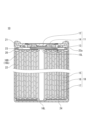
- FIG. 1 is a schematic vertical cross-sectional view of a secondary battery according to an embodiment of the present disclosure.
- the positive electrode according to this embodiment is a positive electrode used in secondary batteries such as non-aqueous electrolyte secondary batteries.
- the positive electrode (P) includes a positive electrode current collector and a positive electrode mixture layer.
- the positive electrode mixture layer is provided on the surface of the positive electrode current collector.
- the positive electrode mixture layer is composed of a positive electrode active material, a carbon conductive assistant, and a positive electrode mixture containing a dispersant.
- the positive electrode active material includes a first metal composite oxide having a first particle size distribution and a second composite metal oxide having a second particle size distribution.
- the volume-based median diameter D1 of the first metal composite oxide and the volume-based median diameter D2 of the second metal composite oxide satisfy D1>D2.
- the first metal composite oxide constitutes active material particles with a large particle size
- the second metal composite oxide constitutes active material particles with a small particle size.
- the small active material particles fill the gaps between the large active material particles. This reduces the gaps in the positive electrode mixture layer and increases the content of the positive electrode active material. In principle, this makes it possible to increase the capacity of the secondary battery.
- the dispersion of the active material particle mixture is not uniform, not only will it be impossible to sufficiently increase the content of the positive electrode active material in the positive electrode mixture layer, but the conductive path will not be properly formed, and the capacity may actually decrease.
- areas with different physical properties will be formed locally in the positive electrode mixture layer, reducing the performance of the positive electrode. For example, areas with high and low reactivity may be formed locally.
- the potential of the positive electrode (P) will vary depending on the area (potential variations will occur). Potential variations in the positive electrode (P) will increase the amount of gas generated by side reactions.
- the positive electrode mixture is dispersed in a liquid component (dispersion medium) to prepare a positive electrode slurry.
- a liquid component dispersion medium
- the positive electrode mixture layer of the positive electrode (P) is composed of a positive electrode mixture with increased dispersibility.
- the first metal composite oxide having a first particle size distribution (hereinafter also referred to as the "first particle group”) and the second composite metal oxide having a second particle size distribution (hereinafter also referred to as the "second particle group") contained in the positive electrode active material may have their respective volume-based median diameters D1 and D2 satisfying D1>D2, but preferably have the following configuration.
- the volume-based median diameter (D) may be measured by separating the positive electrode active material from the positive electrode mixture layer, or may be determined by image analysis of a cross-sectional SEM image of the positive electrode mixture layer. Regardless of which method is used to determine the median diameter (D), roughly the same median diameter (without significant difference) can be obtained.
- the positive electrode mixture layer may be peeled off from the positive electrode (P), immersed in an appropriate solvent to dissolve or swell components other than the active material particles, such as dispersants, and separated by centrifugation.
- the separated positive electrode active material sample is analyzed with a laser diffraction scattering type particle size distribution measuring device to obtain a volume-based particle size distribution.
- the particle diameter of the peak with the largest area in the obtained particle size distribution is the median diameter of either the first particle group or the second particle group, and the particle diameter of the peak with the second largest area is the median diameter of the other.
- the larger median diameter is D1
- the smaller median diameter is D2.
- the positive electrode mixture layer and the positive electrode current collector are simultaneously cut along the width direction of the positive electrode to obtain a cross-sectional sample of the positive electrode in the thickness direction.
- the cross section may be processed using a cross-section polisher (CP) to obtain a cross-sectional sample.
- CP cross-section polisher
- SEM scanning electron microscope
- the area enclosed by the outline is determined from the outline image of the active material particle in the SEM image.
- the diameter of a circle (equivalent circle) having the same area as the area enclosed by the outline of the active material particle is determined and used as the particle size of each particle i.
- the volume of a sphere having the same diameter as the equivalent circle is regarded as the volume Vi of each particle i.
- the volume-based particle size distribution is obtained by determining the diameter and volume of the equivalent circle of any 100 or more particles (preferably 1000 or more). From the obtained particle size distribution, the median diameters D1 and D2, the volume V1 of the first particle group, and the volume V2 of the second particle group can be calculated, in the same way as when separating the positive electrode active material from the positive electrode mixture layer.
- D1 and D2 that satisfy D1>D2 may have a D1/D2 ratio of, for example, 2 or more and 6 or less, or 3 or more and 5 or less.
- D1 may be, for example, 8 ⁇ m or more, 10 ⁇ m or more, 11 ⁇ m or more, 12 ⁇ m or more, or 15 ⁇ m or more. D1 may also be 30 ⁇ m or less, 25 ⁇ m or less, or 20 ⁇ m or less. As described above, it is preferable that D1 be 8 ⁇ D1( ⁇ m) ⁇ 30.
- D2 may be 10 ⁇ m or less, 8 ⁇ m or less, 6 ⁇ m or less, or 5 ⁇ m or less. From the viewpoint of improving the charge/discharge cycle characteristics, D2 may be 1 ⁇ m or more, or 3 ⁇ m or more. As described above, D2 is preferably 1 ⁇ D2( ⁇ m) ⁇ 10.
- Active material particles are usually composed mainly of agglomerates of primary particles, but this is not limited to this.
- the particle size of the primary particles is, for example, 0.2 ⁇ m to 5 ⁇ m.
- the positive electrode may contain only agglomerates of primary particles, but may also be composed partly or entirely of primary particles.
- the compressive strength (single particle breaking strength) F1 of the particles of the first metal composite oxide and the compressive strength F2 of the particles of the second composite oxide satisfy F1 ⁇ F2.
- F1 ⁇ F2 is often the case.
- Active material particles with a small particle size have a large BET specific surface area, and side reactions on the surface of the active material particles tend to increase.
- the positive electrode slurry is applied to the surface of the positive electrode current collector, the coating is dried, and then the coating is rolled. During rolling, the active material particles with a small particle size are crushed and filled so as to fill the gaps between the active material particles with a large particle size. As a result, the electrolyte circulation path is blocked, and the capacity retention rate during charge/discharge cycles including rapid charging is likely to decrease.
- F1/F2 may be less than 1, may be 0.96 or less, preferably 0.6 or less, may be 0.2 or less. F1/F2 may be 0.1 or more and 0.96 or less, or 0.1 or more and 0.9 or less.
- Compressive strength (single particle breaking strength) can be measured using a commercially available measuring device (e.g., Shimadzu Corporation's Micro Compression Tester (MCT-W201)) according to the following procedure.
- MCT-W201 Shimadzu Corporation's Micro Compression Tester
- Particles of the positive electrode active material are spread on the lower pressure plate (SKS flat plate) of the measuring device.
- SSS flat plate lower pressure plate
- the particle diameter here is the equivalent circle diameter (the diameter of a circle having the same area as the particle) determined using an image of the particle taken by an optical microscope.
- the relationship between the load and the deformation of the sample is measured, and the point at which the deformation of the sample changes suddenly (the turning point of the load-deformation profile) is set as the breaking point, and the breaking strength is calculated from the load and particle diameter at that time based on the following formula.
- the breaking strength is calculated as the average value of five measurements.
- St 2.8P/ ⁇ d 2 St: breaking strength [MPa or N/mm 2 ] P: Load [N] d: particle diameter [mm]
- the ratio of the volume V1 of the first particle group to the sum of the volume V1 of the first particle group and the volume V2 of the second particle group (100 x V1/(V1 + V2)) may be, for example, 60 volume % or more and 80 volume % or less, or 70 volume % or more and 80 volume % or less.
- compositions of the first metal composite oxide and the second metal composite oxide are independent of each other and may be the same or different. Even if the compositions are the same, the volume-based median diameter (D) and compressive strength can be freely controlled by the synthesis conditions of the positive electrode active material.
- compositions of the first metal composite oxide and the second metal composite oxide may each independently be represented by the general formula Li y Ni x M (1-x) O 2 , where the general formula satisfies 0.8 ⁇ x and 0 ⁇ y ⁇ 1.2, and M is at least one selected from the group consisting of Co, Mn, Al, Fe, Zr, Ti, Sr, Ca, and B.
- Composite oxides having a composition represented by the above general formula have a high Ni content and are promising as high-capacity positive electrode active materials. It is more preferable that the above general formula satisfies 0.85 ⁇ x.
- Such a composite oxide containing Ni and Li (hereinafter also referred to as “composite oxide (N)”) is advantageous in terms of achieving high capacity and low cost.
- the proportion of Ni in the metal elements other than Li contained in the composite oxide (N) is, as already mentioned, preferably 80 atomic % or more, and may be 85 atomic % or more, or may be 90 atomic % or more.
- the proportion of Ni in the metal elements other than Li is desirably, for example, 95 atomic % or less.
- the composite oxide (N) may be a lithium transition metal composite oxide having a layered rock salt type crystal structure.
- the composite oxide (N) may contain Co, and may contain at least one of Mn and Al. Co, Mn and Al contribute to stabilizing the crystal structure of the composite oxide (N) having a high Ni content.
- the composite oxide (N) may be represented by, for example, the general formula: Li y Ni 1-x1-x2-x3-z Co x1 Mn x2 Al x3 Me z O 2+ ⁇ , where the general formula satisfies 0.9 ⁇ y ⁇ 1.2, 0 ⁇ x1 ⁇ 0.1, 0 ⁇ x2 ⁇ 0.5, 0 ⁇ x3 ⁇ 0.1, 0 ⁇ z ⁇ 0.1, 0.8 ⁇ 1-x1-x2-x3-z, and ⁇ 0.05 ⁇ 0.05, and Me is an element other than Li, Ni, Mn, Al, Co, and oxygen.
- At least one selected from the group consisting of Nb, Zr, B, Mg, Fe, Cu, Zn, Sn, Na, K, Ba, Sr, Ca, W, Mo, Si, Ti, Fe and Cr can be used.
- the content of the elements that make up the active material particles can be measured using an inductively coupled plasma atomic emission spectroscopy (ICP-AES), an electron probe microanalyzer (EPMA), or an energy dispersive X-ray spectroscopy (EDX).
- ICP-AES inductively coupled plasma atomic emission spectroscopy
- EPMA electron probe microanalyzer
- EDX energy dispersive X-ray spectroscopy
- the positive electrode collector may be, for example, in the form of a sheet, and the thickness of the positive electrode collector may be, for example, 5 ⁇ m or more and 20 ⁇ m or less.
- Examples of the material of the positive electrode collector include stainless steel, aluminum, aluminum alloy, and titanium.
- the first metal composite oxide particles and the second metal composite oxide particles may have a surface modification layer containing a boron compound.
- a surface modification layer containing a boron compound.
- the positive electrode mixture of the positive electrode (P) may contain a carbon conductive assistant (C) in order to increase its electronic conductivity.
- C Carbon conductive assistant
- the positive electrode mixture of the positive electrode (P) contains a specific blend of dispersant (hereinafter also referred to as "dispersant (D)") as an auxiliary for enhancing the dispersibility.
- the dispersant (D) contains a nitrile group-containing rubber.
- the dispersant (D) may further contain at least one of a polyvinylpyrrolidone resin and a cellulose resin. By containing these resins, the dispersibility of the positive electrode mixture in the liquid component is further improved.
- dispersant (D) containing nitrile group-containing rubber, polyvinylpyrrolidone resin, and cellulose resin is a combination that even a person skilled in the art would not easily find.
- Nonrile group-containing rubber examples include copolymers of monomers containing acrylonitrile and diene (e.g., butadiene), and acrylonitrile-based rubbers such as acrylonitrile-butadiene rubber (NBR) and hydrogenated acrylonitrile-butadiene rubber (H-NBR).
- NBR acrylonitrile-butadiene rubber
- H-NBR hydrogenated acrylonitrile-butadiene rubber
- the weight average molecular weight of the nitrile group-containing rubber may be in the range of 5,000 to 500,000. In order to enhance the effects of the configuration of the present disclosure, the weight average molecular weight of the nitrile group-containing rubber may be in the range of 10,000 to 300,000.
- the nitrile group-containing rubber has the effect of suppressing the progress of side reactions that can be aggravated by the use of the second particle group that satisfies D1>D2. Side reactions occur at the interface between the electrolyte and the active material particles, and are particularly noticeable when the active material particles are in a charged state. In a secondary battery during charging, the potential of the positive electrode active material is not necessarily constant, and side reactions are promoted around active material particles that have a locally high potential.
- the nitrile group-containing rubber has a high effect of improving the dispersibility of the positive electrode mixture and suppressing potential variations. Therefore, the effect of suppressing side reactions becomes apparent when using a second particle group with a large specific surface area.
- the polyvinylpyrrolidone resin is at least one selected from the group consisting of polyvinylpyrrolidone and polyvinylpyrrolidone derivatives.
- polyvinylpyrrolidone derivatives include polymers in which hydrogen atoms of polyvinylpyrrolidone are replaced with other substituents, such as alkylated polyvinylpyrrolidone.
- the polyvinylpyrrolidone resin only polyvinylpyrrolidone may be used, or a copolymer of vinylpyrrolidone and other monomolecules may be used. Examples of other monomolecules include styrene-based and vinyl acetate-based monomolecules.
- the weight average molecular weight of the polyvinylpyrrolidone resin may be in the range of 1,000 to 2,000,000. In order to enhance the effects of the configuration of the present disclosure, the weight average molecular weight of the polyvinylpyrrolidone resin may be in the range of 5,000 to 1,000,000.
- the cellulose resin may be a cellulose derivative.
- the cellulose derivative include alkyl celluloses such as methyl cellulose and ethyl cellulose, hydroxyalkyl cellulose, and their alkali metal salts.
- alkali metals that form the alkali metal salts include potassium and sodium. Among these, methyl cellulose, ethyl cellulose, and hydroxypropyl methyl cellulose are preferred.
- the weight average molecular weight of the cellulose derivative may be in the range of 1,000 to 1,000,000 (e.g., in the range of 10,000 to 1,000,000). In terms of enhancing the effects of the configuration of the present disclosure, the weight average molecular weight of the cellulose derivative may be in the range of 10,000 to 200,000.
- the amount of the cellulose derivative per 100 parts by mass of the nitrile group-containing rubber is preferably in the range of 10 to 400 parts by mass (for example, in the range of 30 to 400 parts by mass or in the range of 50 to 300 parts by mass).
- the amount in the range of 10 to 400 parts by mass a particularly high effect can be obtained, as shown in the examples.
- the amount of polyvinylpyrrolidone resin per 100 parts by mass of the nitrile group-containing rubber may be in the range of 10 to 400 parts by mass (for example, in the range of 20 to 200 parts by mass). By setting the amount in the range of 10 to 400 parts by mass, a particularly high effect can be obtained, as shown in the examples.
- the dispersibility of the positive electrode mixture is significantly improved, and a positive electrode having a high active material density, low resistance, and suppressed side reactions can be obtained.
- a positive electrode active material that satisfies F1 ⁇ F2 is used, the effect is particularly remarkable. For example, even if the active material density of the positive electrode mixture layer is 3.45 g/cm 3 or more, further 3.55 g/cm 3 or more, or 3.6 g/cm 3 or more, a positive electrode having low resistance and suppressed side reactions can be obtained.
- Polyvinylpyrrolidone resin has a certain effect in improving dispersibility due to its good wettability with carbon conductive assistants, but its electrochemical stability as a single substance is inferior to other dispersants, so long-term dispersion stability tends to decrease when used alone.
- polyvinylpyrrolidone resin is used in combination with cellulose resin and nitrile group-containing rubber, long-term dispersion stability is achieved.
- Cellulose resin and nitrile group-containing rubber are chemically stable and are not easily denatured by the lithium component contained in the active material particles. This further improves the long-term dispersion stability of the positive electrode slurry.
- positive electrode active materials with a high Ni content are prone to side reactions. This makes the effect of the dispersant (D) particularly large.
- the carbon conductive assistant (C) and the dispersant (D) may be used as a dispersion liquid (DL) in combination with a dispersion medium.
- the dispersion liquid (DL) may contain one or more of the above-mentioned dispersants, or may contain other dispersants. Such other dispersants may be known dispersants. However, the proportion of other dispersants in all dispersants is small, for example, 30 mass% or less, more preferably 10 mass% or less.
- the amount of dispersion liquid (DL) used is reflected in the ratio of components in the positive electrode slurry.
- the ratio of components exemplified for the positive electrode mixture can be applied to the ratio of components in the positive electrode slurry.
- the content of dispersant (D) in the positive electrode mixture is, for example, 1.0 mass% or less, and may be 0.01 parts by mass or more and 1 part by mass or less, or 0.05 parts by mass or more and 0.5 parts by mass or less, per 100 parts by mass of the positive electrode active material.
- the positive electrode mixture layer may further include a vinylidene fluoride resin.
- the vinylidene fluoride resin functions as a binder that binds active material particles to each other or between the active material particles and the positive electrode current collector.
- the vinylidene fluoride resin includes a vinylidene fluoride unit as a monomer unit.
- the vinylidene fluoride resin may be a copolymer of vinylidene fluoride and other monomers.
- Examples of the vinylidene fluoride resin include polyvinylidene fluoride (PVDF) and polymers of vinylidene fluoride units and other monomer units (such as tetrafluoroethylene and hexafluoropropylene).
- PVDF polyvinylidene fluoride
- the content of the vinylidene fluoride units contained in the polymer is, for example, 30 mol% or more.
- the weight average molecular weight of the vinylidene fluoride resin may be 800,000 or more, 1,000,000 or more, 1,100,000 or more, 1,200,000 or more, or 1,300,000 or more.
- the weight average molecular weight of the vinylidene fluoride resin may be 2,000,000 or less, or 1,800,000 or less.
- Vinylidene fluoride resins are not included in the examples of dispersants.
- the amount of vinylidene fluoride resin per 100 parts by mass of dispersant (D) may be, for example, in the range of 50 to 2000 parts by mass (e.g., in the range of 100 to 1000 parts by mass).
- the amount of vinylidene fluoride resin relative to 100 parts by mass of the positive electrode active material may be, for example, 0.1 parts by mass or more, or 0.5 parts by mass or more, and may be 2.0 parts by mass or less, or 1.5 parts by mass or less.
- the positive electrode mixture layer may contain a carbon conductive assistant other than CNT.
- carbon conductive assistants include conductive carbon materials such as graphene and carbon black (acetylene black, ketjen black, furnace black, etc.).
- the proportion of CNT in all carbon materials (conductive assistants) is, for example, 10% by mass or more, and is preferably in the range of 30 to 100% by mass (for example, in the range of 50 to 100% by mass).
- the amount of CNTs per 100 parts by mass of the positive electrode active material may be 0.01 parts by mass or more, or 0.04 parts by mass or more, or may be 1 part by mass or less, or 0.5 parts by mass or less.
- the length (average length) of the CNTs may be 1 ⁇ m or more.
- the average aspect ratio of the CNTs ratio of length to diameter of the fiber
- CNTs with a large aspect ratio are more likely to come into contact with the positive electrode active material and the positive electrode current collector.
- CNTs have excellent electrical conductivity. Therefore, by using CNTs, the direct current resistance (DCR) of the battery can be significantly reduced.
- the average length of the CNTs is preferably 1 ⁇ m or more from the viewpoint of increasing the conductivity in the positive electrode mixture layer.
- the upper limit of the length of the CNTs is not particularly limited, but it is preferable that it is not too large compared to the particle size of the positive electrode active material.
- the average length of the CNTs may be 1 ⁇ m or more or 5 ⁇ m or more, and may be 20 ⁇ m or less or 10 ⁇ m or less.
- the CNTs present in the positive electrode mixture layer may be in the form of a bundle of multiple CNTs. The length of a single CNT present in the bundle of CNTs is used to calculate the above average length.
- the diameter (average diameter) of the CNTs may be 20 nm or less, 15 nm or less, or 1 nm or more. By making the average diameter 20 nm or less, a high effect can be obtained with a small amount.
- the average diameter of CNTs is determined by image analysis using a transmission electron microscope (TEM).
- the average diameter of CNTs can be measured by the following method. First, 100 CNTs are randomly selected, and the diameter (outer diameter) of each is measured at one random location. The average diameter is then determined by taking the arithmetic average of the measured diameters.
- the CNTs may be either single-walled CNTs (SWCNTs) or multi-walled (MWCNTs). Examples of multi-walled CNTs include two-walled CNTs, three-walled CNTs, and four or more-walled CNTs.
- the positive electrode mixture layer preferably contains single-walled CNTs and/or multi-walled CNTs.
- the multi-walled CNTs contained in the positive electrode mixture layer may be one type of multi-walled CNT or multiple types of multi-walled CNTs with different numbers of layers.
- the BET specific surface area of the CNT may be 200 m 2 /g or more, 250 m 2 /g or more, or 300 m 2 /g or more.
- the upper limit of the BET specific surface area is not particularly limited, but may be 1000 m 2 /g or less.
- the BET specific surface area of the CNT can be measured by a nitrogen adsorption method. However, there is generally a correlation between the BET specific surface area of the CNT and the fiber diameter and fiber length.
- the BET specific surface area is 200 m 2 /g or more and 300 m 2 /g or less. Therefore, even in the state of a battery, the BET specific surface area of the CNT can be calculated with high accuracy.
- the method for producing active material particles includes, for example, a synthesis step, a washing step, a drying step, and an addition step. Note that the active material particles may be produced by a method other than the following production method.
- Metal hydroxides can be obtained, for example, by dropping an alkaline solution such as sodium hydroxide into a stirred solution of metal salts containing the metal elements that make up the composite oxide particles, adjusting the pH to the alkaline side (e.g., 8.5 to 12.5), and allowing precipitation (co-precipitation).
- alkaline solution such as sodium hydroxide
- adjusting the pH to the alkaline side e.g., 8.5 to 12.5
- precipitation co-precipitation
- Li compounds include Li2CO3 , LiOH, Li2O2 , Li2O , LiNO3 , LiNO2 , Li2SO4 , LiOH.H2O , LiH, LiF, etc.
- the mixing ratio of the metal hydroxide (metal oxide) and the Li compound is preferably such that the molar ratio of metal elements excluding Li:Li is in the range of 1: 0.98 to 1:1.1.
- the alkaline component is likely to cause a change in the state of the positive electrode slurry by reacting with a binder such as polyvinylidene fluoride, and tends to make the state of the positive electrode slurry unstable.
- the mixture of metal hydroxide (metal oxide) and Li compound, etc. is fired, for example, in an oxygen atmosphere (flowing gas with an oxygen concentration of 80% or more).
- the firing conditions may be such that the heating rate from 450°C to 680°C is in the range of more than 1.0°C/min to 5.5°C/min, and the maximum temperature reached is in the range of 700°C to 850°C.
- the heating rate from over 680°C to the maximum temperature reached may be, for example, 0.1°C/min to 3.5°C/min.
- the holding time of the maximum temperature reached may be 1 hour to 30 hours.
- This firing process may be a multi-stage firing, and the heating rate may be set multiple times for each temperature range as long as it is within the above-specified range.
- the particle size of the single particles can be adjusted by adjusting the firing conditions. For example, the particle size of the single particles can be increased by increasing the maximum temperature reached.
- the composite oxide particles obtained in the synthesis step are washed with water and dehydrated to obtain a cake-like composition.
- the washing and dehydration can be performed by known methods and conditions. These may be performed within a range in which lithium is not eluted from the composite oxide particles and the battery characteristics are not deteriorated.
- Ca compounds, Sr compounds, Fe compounds, Cu compounds, Zr compounds, Mg compounds, Si compounds, Cr compounds, Ti compounds, S compounds, fluorides, etc. may be added to the cake-like composition.
- the cake-like composition obtained in the washing step is dried to obtain a powder-like composition.
- the drying step may be performed in a vacuum atmosphere.
- the drying conditions are, for example, 150°C to 400°C and 0.5 hours to 15 hours.
- a boron-containing compound such as boric acid (H 3 BO 3 ) is added to the powder composition obtained in the drying step, and the temperature is raised to 200° C. to 400° C. This allows a surface modification layer containing the boron compound to be formed on the surface of the lithium transition metal composite oxide.
- the amount of the boron-containing compound added is, for example, 0.1 mol % to 7 mol % with respect to the total molar amount of metal elements excluding Li in the composite oxide particles.
- the positive electrode active material (first particle group and second particle group) is obtained.
- the positive electrode active material may be produced by a method other than the synthesis process described above, or may be produced by a known method.
- the content of the positive electrode active material in the positive electrode mixture layer is determined using a sample of the positive electrode mixture.
- a sample of the positive electrode mixture is obtained by the following procedure. First, the secondary battery in a discharged state is disassembled and the positive electrode is removed. Next, the positive electrode is washed with an organic solvent and then vacuum dried. After that, only the positive electrode mixture layer is removed, and the removed positive electrode mixture layer is used as the mixture sample.
- TG-DTA, NMR, pyrolysis GC-MS, and other analyses on the mixture sample, the ratio of dispersant, binder, and carbon conductive assistant other than the positive electrode active material can be calculated.
- the ratio of carbon nanotubes in the conductive assistant can be calculated by combining thermal analysis such as TG-DTA and microscopic Raman spectroscopy on the cross section of the positive electrode mixture layer.
- the mass per m 2 of the positive electrode mixture layer may be 200 g or more, and is preferably 250 g or more. By making the mass 250 g or more, it is possible to increase the capacity of the secondary battery. As described above, according to the positive electrode according to the present disclosure, the adverse effects caused by increasing the mass can be suppressed.
- the mass can be increased by thickening the positive electrode mixture layer or increasing the density of the positive electrode mixture layer.
- the mass per m 2 of the positive electrode mixture layer (one layer) is large, the distribution of the auxiliary agent is likely to become non-uniform during drying of the positive electrode slurry in which the positive electrode mixture is dispersed in the liquid component (dispersion medium) in the manufacturing process of the positive electrode mixture layer, and the capacity decrease becomes significant. Therefore, it is particularly important to increase the dispersibility of the positive electrode mixture.
- the mass per m 2 of the positive electrode mixture layer (one layer) is 320 g/m 2 , and sufficient battery characteristics are ensured in both cases.
- the thickness of the positive electrode mixture layer may be in the range of 50 ⁇ m to 250 ⁇ m. According to this embodiment, even if the positive electrode mixture layer is made thick, an increase in internal resistance can be suppressed.
- the positive electrode current collector is composed of a sheet-like conductive material.
- a non-porous conductive substrate metal foil, etc.
- a porous conductive substrate mesh, net, punched sheet, etc.
- the thickness of the positive electrode current collector is not particularly limited, but is, for example, 3 to 50 ⁇ m, and can be selected according to the application.
- Examples of the material of the positive electrode current collector include stainless steel, aluminum, aluminum alloy, and titanium.
- the positive electrode mixture layer may be formed on only one side of the positive electrode current collector, or may be formed on both sides of the positive electrode current collector.
- the positive electrode slurry according to this embodiment includes the above-mentioned components of the positive electrode mixture and a liquid component (dispersion medium) in which they are dispersed.
- the positive electrode mixture includes at least a positive electrode active material, a carbon conductive assistant (e.g., CNT), and a dispersant (D), and the positive electrode active material includes a first metal composite oxide having a first particle size distribution and a second composite metal oxide having a second particle size distribution.
- the volume-based median diameter D1 of the first metal composite oxide and the volume-based median diameter D2 of the second metal composite oxide satisfy D1>D2.
- the dispersant (D) includes a nitrile group-containing rubber, and may further include a polyvinylpyrrolidone resin and a cellulose resin.
- the positive electrode mixture further includes a binder (e.g., polyvinylidene fluoride).
- the liquid component (dispersion medium) is not particularly limited, and water, organic solvents, and mixtures thereof may be used.
- organic solvents include protic solvents such as alcohols (e.g., ethanol), and aprotic solvents such as ethers (e.g., tetrahydrofuran), amides (e.g., dimethylformamide), and N-methyl-2-pyrrolidone (NMP).
- the ratio of the components contained in the positive electrode slurry is reflected in the ratio of the components in the positive electrode mixture layer. Therefore, by changing the ratio of the components contained in the positive electrode slurry, the ratio of the components in the positive electrode mixture layer can be changed.
- the ratios of the components exemplified for the positive electrode mixture layer can be applied to the ratios of the components in the positive electrode slurry.
- the positive electrode may be formed by the following method. First, a positive electrode slurry is prepared by dispersing a positive electrode mixture in a liquid component (dispersion medium). Next, the positive electrode slurry is applied to the surface of a positive electrode collector to form a coating film, and the coating film is then dried to form a positive electrode mixture layer. The dried coating film may be rolled as necessary.
- the positive electrode mixture layer may be formed on one surface or both surfaces of the positive electrode collector.
- the secondary battery includes the above-mentioned positive electrode for secondary batteries, a separator, a negative electrode facing the positive electrode via the separator, and an electrolyte.
- the secondary battery may include an exterior body. Examples of the secondary battery include a lithium ion secondary battery and a lithium metal secondary battery.
- the components other than the positive electrode mixture layer are not particularly limited, and known components may be used. Examples of the components of the secondary battery other than the positive electrode are described below.
- the negative electrode typically includes a negative electrode mixture layer containing a negative electrode active material.
- the negative electrode may include a negative electrode current collector and a negative electrode mixture layer disposed on the negative electrode current collector.
- the negative electrode may be a negative electrode current collector on which lithium metal or a lithium alloy can be deposited.
- the negative electrode mixture layer is composed of a negative electrode mixture, which contains a negative electrode active material as an essential component.
- the negative electrode mixture may contain optional components such as a binder, a thickener, and a conductive assistant.
- the optional components may include the components exemplified as the components of the positive electrode.
- the negative electrode mixture layer may be formed by applying a negative electrode slurry, in which the components of the negative electrode mixture are dispersed in a dispersion medium, to the surface of the negative electrode current collector and drying the coating. The dried coating may be rolled as necessary.
- the dispersion medium may be any of the dispersion media exemplified as the dispersion medium for the positive electrode slurry.
- the negative electrode mixture layer may be formed on only one side of the negative electrode current collector, or on both sides of the negative electrode current collector.
- Si-containing material examples include simple Si, silicon alloys, silicon compounds (such as silicon oxides), and composite materials in which a silicon phase is dispersed in a lithium ion conductive phase (matrix).
- silicon oxides include SiO x particles. x may be, for example, 0.5 ⁇ x ⁇ 2, or 0.8 ⁇ x ⁇ 1.6.
- the lithium ion conductive phase at least one selected from the group consisting of a SiO 2 phase, a silicate phase, and a carbon phase may be used.
- the negative electrode current collector may be a metal foil.
- the negative electrode current collector may be porous. Examples of materials for the negative electrode current collector include stainless steel, nickel, nickel alloys, copper, and copper alloys.
- the non-aqueous electrolyte may be a liquid electrolyte (electrolytic solution), a gel electrolyte, or a solid electrolyte.
- the gel electrolyte contains a lithium salt and a matrix polymer, or a lithium salt, a non-aqueous solvent, and a matrix polymer.
- a matrix polymer for example, a polymer material that absorbs the non-aqueous solvent and gels is used. Examples of the polymer material include fluororesin, acrylic resin, polyether resin, and polyethylene oxide.
- the liquid electrolyte (electrolytic solution) contains a non-aqueous solvent and an electrolyte salt dissolved in the non-aqueous solvent.
- the electrolyte salt contains at least a lithium salt.
- the concentration of the lithium salt in the non-aqueous electrolyte is, for example, 0.5 mol/L or more and 2 mol/L or less.
- a known material can be used as the non-aqueous solvent.
- cyclic carbonate esters, chain carbonate esters, cyclic carboxylate esters, chain carboxylate esters, etc. are used as the non-aqueous solvent.
- examples of cyclic carbonate esters include propylene carbonate (PC), ethylene carbonate (EC), fluoroethylene carbonate (FEC), vinylene carbonate (VC), etc.
- Chain carbonate esters include diethyl carbonate (DEC), ethyl methyl carbonate (EMC), dimethyl carbonate (DMC), etc.
- examples of cyclic carboxylate esters include ⁇ -butyrolactone (GBL), ⁇ -valerolactone (GVL), etc.
- chain carboxylate esters examples include non-aqueous solvents such as methyl acetate, ethyl acetate, propyl acetate, methyl propionate (MP), and ethyl propionate (EP).
- the non-aqueous solvents may be used alone or in combination of two or more.
- lithium salts include lithium salts of chlorine-containing acids ( LiClO4 , LiAlCl4 , LiB10Cl10 , etc. ), lithium salts of fluorine-containing acids ( LiPF6 , LiPF2O2 , LiBF4 , LiSbF6 , LiAsF6 , LiCF3SO3 , LiCF3CO2 , etc.), lithium salts of fluorine-containing acid imides (LiN( FSO2 ) 2 , LiN( CF3SO2 ) 2 , LiN ( CF3SO2 )( C4F9SO2 ) , LiN ( C2F5SO2 ) 2 , etc. ), lithium halides ( LiCl, LiBr, LiI, etc. ) , and the like.
- the lithium salt may be used alone or in combination of two or more kinds.
- the concentration of the lithium salt in the electrolyte may be 1 mol/L or more and 2 mol/L or less, or 1 mol/L or more and 1.5 mol/L or less.
- the electrolyte may contain known additives.
- additives include 1,3-propane sultone, methylbenzenesulfonate, cyclohexylbenzene, biphenyl, diphenyl ether, fluorobenzene, etc.
- the separator is disposed between the positive electrode and the negative electrode.
- the separator preferably has high ion permeability and appropriate mechanical strength and insulating properties.
- a microporous thin film, a woven fabric, a nonwoven fabric, etc. can be used.
- Examples of the material of the separator include polyolefins (polypropylene, polyethylene, etc.) and other resins.
- the electrode group and the non-aqueous electrolyte are housed in the exterior body (battery case).
- the exterior body is not particularly limited, and a known exterior body may be used.
- the electrode group is composed of a positive electrode, a negative electrode, and a separator.
- the configuration of the electrode group is not particularly limited, and may be a wound type or a laminated type.
- the wound type electrode group is formed by winding the positive electrode and the negative electrode with the separator interposed therebetween.
- the laminated type electrode group is formed by stacking the positive electrode and the negative electrode with the separator interposed therebetween.
- the shape of the non-aqueous electrolyte secondary battery is not particularly limited, and may be a cylindrical shape, a square shape, a coin shape, a button shape, a laminate shape, or the like.
- FIG. 1 is a longitudinal cross-sectional view of a cylindrical secondary battery 10 (hereinafter also simply referred to as "battery 10") according to the present disclosure.
- battery 10 a cylindrical secondary battery 10
- the present disclosure is not limited to the following configuration.
- a positive electrode lead 15L derived from the positive electrode 15 is connected to the metal plate 13.
- the valve body 12 functions as an external terminal of the positive electrode 15 and also functions as a safety valve.
- the negative electrode lead 16L derived from the negative electrode 16 is connected to the inner bottom surface of the battery case 22.
- An annular groove 22a is formed near the open end of the battery case 22.
- a first insulating plate 23 is disposed between one end surface of the electrode group 18 and the annular groove 22a.
- a second insulating plate 24 is disposed between the other end surface of the electrode group 18 and the bottom of the battery case 22.
- the electrode group 18 is formed by winding the positive electrode 15 and the negative electrode 16 in a cylindrical shape with the separator 17 interposed therebetween.
- the outermost periphery of the electrode group 18 is formed on the winding end side of the negative electrode 16. That is, in the electrode group 18, the outermost periphery of the negative electrode 16 is disposed outside the outermost periphery of the positive electrode 15.
- the outermost periphery of the electrode group 18 is composed of the negative electrode current collector 16b at the end 16D of the negative electrode 16, which is wound around the outer surface of the inner negative electrode 16 without going through the positive electrode 15, but this structure is only one example and is not limited to this structure.
- a battery A1 was prepared in the following manner.
- a negative electrode active material, sodium carboxymethylcellulose (CMC-Na), styrene-butadiene rubber (SBR), and water were mixed in a predetermined mass ratio to prepare a negative electrode slurry.
- the negative electrode slurry was applied to the surface of a copper foil (negative electrode current collector) to form a laminate including the copper foil and the coating film formed on the copper foil.
- the laminate was rolled. In this way, a negative electrode including the copper foil and the negative electrode mixture layer formed on both sides of the copper foil was formed.
- a positive electrode active material, a dispersant (D), MWCNT (carbon conductive assistant), polyvinylidene fluoride (binder), and N-methyl-2-pyrrolidone (dispersion medium) were mixed in a predetermined mass ratio to prepare a positive electrode slurry.
- the first metal oxide particles were a first particle group with a median diameter D1 of 14 ⁇ m
- the first particle group and the second particle group were mixed in a volume ratio of 8:2.
- the average length of the MWCNTs was 1-5 ⁇ m, and the average diameter was 10 nm.
- the amount of CNTs was 0.5 parts by mass per 100 parts by mass of the positive electrode active material.
- the weight-average molecular weight of polyvinylidene fluoride was 1.3 million.
- the amount of polyvinylidene fluoride was 1.0 part by mass per 100 parts by mass of the positive electrode active material.
- Dispersant (D) contains polyvinylpyrrolidone (PVP), ethyl cellulose (eC) and nitrile group-containing rubber (hydrogenated nitrile rubber (HNBR)).
- PVP polyvinylpyrrolidone
- eC ethyl cellulose
- HNBR hydrogenated nitrile rubber
- the amount of polyvinylpyrrolidone (PVP) per 100 parts by mass of hydrogenated nitrile rubber (HNBR) is 100 parts by mass.
- a coating film was formed on the surface of an aluminum foil (positive electrode current collector) by applying the positive electrode slurry, and a laminate of the aluminum foil and the coating film was obtained. Next, the coating film was dried, and the laminate was rolled. In this way, a positive electrode including an aluminum foil and a positive electrode mixture layer formed on both sides of the aluminum foil was produced.
- the active material density in the positive electrode mixture layer was 3.5 g/ cm3 .
- the electrolyte was prepared by adding LiPF6 (lithium salt) to a non-aqueous solvent.
- concentration of LiPF6 in the electrolyte was 1.0 mol/L.
- a positive electrode was produced in the same manner and under the same conditions as for Battery A1, except that the laminate of the aluminum foil and the coating was rolled until the active material density in the positive electrode mixture layer became 3.6 g/ cm3 , and thus a secondary battery A2 was produced.
- a positive electrode was produced in the same manner and under the same conditions as those for Battery A1, except that 0.2 parts by mass of a nitrile group-containing rubber was used as a dispersant relative to 100 parts by mass of the positive electrode active material, to produce a secondary battery A3.
- the active material density in the positive electrode mixture layer was 3.5 g/ cm3 .
- a positive electrode was produced in the same manner and under the same conditions as those for the battery A3, except that 1.5 parts by mass of acetylene black (AB) was used per 100 parts by mass of the positive electrode active material instead of MWCNT as the carbon conductive assistant, and a secondary battery A4 was produced.
- the active material density in the positive electrode mixture layer was 3.5 g/ cm3 .
- a positive electrode was produced in the same manner and under the same conditions as those for the battery A4, except that the weight-average molecular weight of the polyvinylidene fluoride was 1,000,000, to produce a secondary battery A5.
- the active material density in the positive electrode mixture layer was 3.5 g/cm 3 .
- a positive electrode was produced in the same manner and under the same conditions as the battery A1 , except that particles of a second metal composite oxide (NCA) represented by the composition formula LiNi 0.85 Co 0.10 Al 0.05 O 2 were used, and the laminate of the aluminum foil and the coating film was rolled until the active material density in the positive electrode mixture layer was 3.6 g / cm 3.
- the second particle group had a median diameter D2 of 4 ⁇ m, and the first particle group and the second particle group were mixed in a volume ratio of 8: 2.
- a secondary battery B2 was produced by preparing a positive electrode in the same manner and under the same conditions as those of the battery A1, except that only polyvinylpyrrolidone (PVP) was used as a dispersant in an amount of 0.2 parts by mass per 100 parts by mass of the positive electrode active material.
- the active material density in the positive electrode mixture layer was 3.5 g/ cm3 .
- a positive electrode was produced in the same manner and under the same conditions as those for the battery A1, except that 0.2 parts by mass of ethyl cellulose (eC) was used as a dispersant relative to 100 parts by mass of the positive electrode active material, to produce a secondary battery B2.
- the active material density in the positive electrode mixture layer was 3.5 g/ cm3 .
- Table 1 shows an outline of the configuration of each positive electrode.
- ⁇ Plate resistance> A square test piece of 5 cm x 5 cm was punched out from the prepared positive electrode, and the mixture layer resistance and the interface resistance were measured using an electrical resistance measuring system RM2610 manufactured by HIOKI ELECTRIC INC. The mixture layer resistance at this time was taken as the electrode plate resistance.
- the positive electrode of battery A1 in Example 1 had high liquid absorption (large pore diameter), low plate resistance, and good battery characteristics. This result was due to the improved dispersibility of the positive electrode mixture. In addition, by making F1 ⁇ F2, cracking of the active material particles was suppressed. Furthermore, battery A2 in Example 2 had even smaller plate resistance and improved rapid charging cycle characteristics, despite the increased active material density.
- the positive electrode of Battery A3 in Example 3 showed a slight increase in plate resistance, but generally showed good results.
- Battery A4 in Example 4 and Battery A5 in Example 5 showed reduced liquid absorption, increased plate resistance, and deteriorated battery characteristics, but showed better results than Batteries B1 to B3 in Comparative Examples 1 to 3.
- the results for Battery B1 are related to the fact that F1 > F2. It is believed that cracks in the active material particles reduced the electrolyte flow paths, causing the rapid charging cycle characteristics to deteriorate.
- Secondary batteries equipped with the high-capacity, high-performance secondary battery positive electrodes disclosed herein are useful as the main power sources for mobile communication devices, portable electronic devices, electric vehicles, etc.
Landscapes
- Chemical & Material Sciences (AREA)
- Chemical Kinetics & Catalysis (AREA)
- Electrochemistry (AREA)
- General Chemical & Material Sciences (AREA)
- Engineering & Computer Science (AREA)
- Composite Materials (AREA)
- Materials Engineering (AREA)
- Inorganic Chemistry (AREA)
- Manufacturing & Machinery (AREA)
- Battery Electrode And Active Subsutance (AREA)
Priority Applications (3)
| Application Number | Priority Date | Filing Date | Title |
|---|---|---|---|
| EP24815520.2A EP4723198A1 (en) | 2023-05-31 | 2024-05-29 | Positive electrode for secondary battery, and secondary battery |
| JP2025524133A JPWO2024248039A1 (https=) | 2023-05-31 | 2024-05-29 | |
| CN202480034877.4A CN121263875A (zh) | 2023-05-31 | 2024-05-29 | 二次电池用正极和二次电池 |
Applications Claiming Priority (2)
| Application Number | Priority Date | Filing Date | Title |
|---|---|---|---|
| JP2023090332 | 2023-05-31 | ||
| JP2023-090332 | 2023-05-31 |
Publications (1)
| Publication Number | Publication Date |
|---|---|
| WO2024248039A1 true WO2024248039A1 (ja) | 2024-12-05 |
Family
ID=93658137
Family Applications (1)
| Application Number | Title | Priority Date | Filing Date |
|---|---|---|---|
| PCT/JP2024/019703 Ceased WO2024248039A1 (ja) | 2023-05-31 | 2024-05-29 | 二次電池用正極および二次電池 |
Country Status (4)
| Country | Link |
|---|---|
| EP (1) | EP4723198A1 (https=) |
| JP (1) | JPWO2024248039A1 (https=) |
| CN (1) | CN121263875A (https=) |
| WO (1) | WO2024248039A1 (https=) |
Citations (7)
| Publication number | Priority date | Publication date | Assignee | Title |
|---|---|---|---|---|
| JP2015043257A (ja) * | 2011-12-22 | 2015-03-05 | パナソニック株式会社 | 二次電池用正極板およびこれを用いた二次電池 |
| JP5868604B2 (ja) | 2010-03-31 | 2016-02-24 | 三星エスディアイ株式会社Samsung SDI Co.,Ltd. | 正極活物質、並びにそれを採用した正極及びリチウム電池 |
| KR20210019389A (ko) * | 2019-08-12 | 2021-02-22 | 주식회사 엘지화학 | 리튬 이차전지용 양극 및 이를 포함하는 리튬 이차전지 |
| WO2021153397A1 (ja) * | 2020-01-31 | 2021-08-05 | パナソニックIpマネジメント株式会社 | 二次電池用正極および二次電池 |
| WO2022210902A1 (ja) * | 2021-03-31 | 2022-10-06 | パナソニックIpマネジメント株式会社 | 導電材分散液、非水電解質二次電池用の正極スラリー、非水電解質二次電池用正極、および非水電解質二次電池 |
| WO2023054308A1 (ja) * | 2021-09-30 | 2023-04-06 | パナソニックIpマネジメント株式会社 | 非水電解質二次電池 |
| WO2024070704A1 (ja) * | 2022-09-29 | 2024-04-04 | パナソニックIpマネジメント株式会社 | 非水電解質二次電池用の正極、それを用いた非水電解質二次電池、および、非水電解質二次電池の正極用の正極スラリー |
-
2024
- 2024-05-29 EP EP24815520.2A patent/EP4723198A1/en active Pending
- 2024-05-29 JP JP2025524133A patent/JPWO2024248039A1/ja active Pending
- 2024-05-29 CN CN202480034877.4A patent/CN121263875A/zh active Pending
- 2024-05-29 WO PCT/JP2024/019703 patent/WO2024248039A1/ja not_active Ceased
Patent Citations (7)
| Publication number | Priority date | Publication date | Assignee | Title |
|---|---|---|---|---|
| JP5868604B2 (ja) | 2010-03-31 | 2016-02-24 | 三星エスディアイ株式会社Samsung SDI Co.,Ltd. | 正極活物質、並びにそれを採用した正極及びリチウム電池 |
| JP2015043257A (ja) * | 2011-12-22 | 2015-03-05 | パナソニック株式会社 | 二次電池用正極板およびこれを用いた二次電池 |
| KR20210019389A (ko) * | 2019-08-12 | 2021-02-22 | 주식회사 엘지화학 | 리튬 이차전지용 양극 및 이를 포함하는 리튬 이차전지 |
| WO2021153397A1 (ja) * | 2020-01-31 | 2021-08-05 | パナソニックIpマネジメント株式会社 | 二次電池用正極および二次電池 |
| WO2022210902A1 (ja) * | 2021-03-31 | 2022-10-06 | パナソニックIpマネジメント株式会社 | 導電材分散液、非水電解質二次電池用の正極スラリー、非水電解質二次電池用正極、および非水電解質二次電池 |
| WO2023054308A1 (ja) * | 2021-09-30 | 2023-04-06 | パナソニックIpマネジメント株式会社 | 非水電解質二次電池 |
| WO2024070704A1 (ja) * | 2022-09-29 | 2024-04-04 | パナソニックIpマネジメント株式会社 | 非水電解質二次電池用の正極、それを用いた非水電解質二次電池、および、非水電解質二次電池の正極用の正極スラリー |
Also Published As
| Publication number | Publication date |
|---|---|
| JPWO2024248039A1 (https=) | 2024-12-05 |
| CN121263875A (zh) | 2026-01-02 |
| EP4723198A1 (en) | 2026-04-08 |
Similar Documents
| Publication | Publication Date | Title |
|---|---|---|
| JP7829155B2 (ja) | 非水電解質二次電池用正極およびそれを用いた非水電解質二次電池 | |
| JP7821994B2 (ja) | 電池および電池の製造方法 | |
| JP6059019B2 (ja) | 非水電解質二次電池 | |
| WO2018225515A1 (ja) | 非水電解質二次電池用負極及び非水電解質二次電池 | |
| WO2016136227A1 (ja) | 非水電解質二次電池 | |
| JP6697377B2 (ja) | リチウムイオン二次電池 | |
| WO2015004841A1 (ja) | 非水電解質二次電池 | |
| JP2022530297A (ja) | 負極材料、負極片、電気化学装置及び電子装置 | |
| JP2016031881A (ja) | 非水電解質二次電池 | |
| WO2020213499A1 (ja) | 非水電解質二次電池用の負極、及び非水電解質二次電池 | |
| US9761854B2 (en) | Spirally-wound electrode assembly for rechargeable lithium battery and rechargeable lithium battery including same | |
| JP4222519B2 (ja) | リチウムイオン二次電池およびこれを用いた機器 | |
| JP2007265731A (ja) | リチウムイオン二次電池 | |
| WO2024248043A1 (ja) | 二次電池用正極、二次電池および正極合剤スラリー | |
| JP2007095534A (ja) | 非水電解液二次電池の製造方法 | |
| JP7780729B2 (ja) | 正極材料および電池 | |
| WO2024070705A1 (ja) | 非水電解質二次電池用の正極、それを用いた非水電解質二次電池、および、導電材分散液 | |
| WO2024070706A1 (ja) | 非水電解質二次電池用の正極、それを用いた非水電解質二次電池、および、導電材分散液 | |
| WO2024070220A1 (ja) | 非水電解質二次電池 | |
| WO2024248039A1 (ja) | 二次電池用正極および二次電池 | |
| JP6468025B2 (ja) | 非水系リチウム二次電池 | |
| JP4456668B2 (ja) | 非水二次電池とその正極 | |
| WO2014115322A1 (ja) | リチウムイオン二次電池用負極活物質及びそれらを用いたリチウムイオン二次電池 | |
| JP2017228710A (ja) | リチウムイオンキャパシタ及びリチウムイオンキャパシタ用電解液 | |
| WO2024070502A1 (ja) | 非水電解質二次電池用の正極、それを用いた非水電解質二次電池、および、非水電解質二次電池の正極用の正極スラリー |
Legal Events
| Date | Code | Title | Description |
|---|---|---|---|
| 121 | Ep: the epo has been informed by wipo that ep was designated in this application |
Ref document number: 24815520 Country of ref document: EP Kind code of ref document: A1 |
|
| ENP | Entry into the national phase |
Ref document number: 2025524133 Country of ref document: JP Kind code of ref document: A |
|
| WWE | Wipo information: entry into national phase |
Ref document number: 202547123451 Country of ref document: IN |
|
| NENP | Non-entry into the national phase |
Ref country code: DE |
|
| WWE | Wipo information: entry into national phase |
Ref document number: 2024815520 Country of ref document: EP |
|
| ENP | Entry into the national phase |
Ref document number: 2024815520 Country of ref document: EP Effective date: 20260102 |
|
| ENP | Entry into the national phase |
Ref document number: 2024815520 Country of ref document: EP Effective date: 20260102 |
|
| ENP | Entry into the national phase |
Ref document number: 2024815520 Country of ref document: EP Effective date: 20260102 |
|
| ENP | Entry into the national phase |
Ref document number: 2024815520 Country of ref document: EP Effective date: 20260102 |
|
| ENP | Entry into the national phase |
Ref document number: 2024815520 Country of ref document: EP Effective date: 20260102 |
|
| ENP | Entry into the national phase |
Ref document number: 2024815520 Country of ref document: EP Effective date: 20260102 |
|
| WWP | Wipo information: published in national office |
Ref document number: 2024815520 Country of ref document: EP |