WO2024247083A1 - 制御装置、弁装置、プログラム、プログラムを記憶する記憶媒体、及び、制御方法 - Google Patents
制御装置、弁装置、プログラム、プログラムを記憶する記憶媒体、及び、制御方法 Download PDFInfo
- Publication number
- WO2024247083A1 WO2024247083A1 PCT/JP2023/020025 JP2023020025W WO2024247083A1 WO 2024247083 A1 WO2024247083 A1 WO 2024247083A1 JP 2023020025 W JP2023020025 W JP 2023020025W WO 2024247083 A1 WO2024247083 A1 WO 2024247083A1
- Authority
- WO
- WIPO (PCT)
- Prior art keywords
- motor
- origin
- control
- drive current
- setting process
- Prior art date
- Legal status (The legal status is an assumption and is not a legal conclusion. Google has not performed a legal analysis and makes no representation as to the accuracy of the status listed.)
- Ceased
Links
Images







Classifications
-
- H—ELECTRICITY
- H02—GENERATION; CONVERSION OR DISTRIBUTION OF ELECTRIC POWER
- H02P—CONTROL OR REGULATION OF ELECTRIC MOTORS, ELECTRIC GENERATORS OR DYNAMO-ELECTRIC CONVERTERS; CONTROLLING TRANSFORMERS, REACTORS OR CHOKE COILS
- H02P23/00—Arrangements or methods for the control of AC motors characterised by a control method other than vector control
- H02P23/04—Arrangements or methods for the control of AC motors characterised by a control method other than vector control specially adapted for damping motor oscillations, e.g. for reducing hunting
-
- H—ELECTRICITY
- H02—GENERATION; CONVERSION OR DISTRIBUTION OF ELECTRIC POWER
- H02P—CONTROL OR REGULATION OF ELECTRIC MOTORS, ELECTRIC GENERATORS OR DYNAMO-ELECTRIC CONVERTERS; CONTROLLING TRANSFORMERS, REACTORS OR CHOKE COILS
- H02P29/00—Arrangements for regulating or controlling electric motors, appropriate for both AC and DC motors
- H02P29/40—Regulating or controlling the amount of current drawn or delivered by the motor for controlling the mechanical load
Definitions
- the present disclosure relates to a control device and control method for performing position control processing of a motor, a valve device equipped with such a control device, a program executed by a computer of such a control device, and a storage medium for storing the program.
- the control device is a control device configured to perform an origin setting process that controls a motor so that a movable part of an electric device driven by the motor is further pressed against a stopper while in contact with the stopper, thereby setting the origin position of the motor, and a position control process that controls the rotational position of the motor relative to the origin position, and is equipped with a current setting unit configured to change the drive current to the motor in the origin setting process so that the drive current to the motor is smaller than the drive current to the motor in the position control process.
- a program causes a computer of a control device for an electric device using a motor as a drive source to function as an origin setting unit configured to set an origin position of the motor by controlling the motor of the control device so that a movable part of the electric device is further pressed against a stopper while in contact with the stopper, a position control unit configured to control the rotational position of the motor relative to the origin position, and a current setting unit configured to change the drive current so that the drive current when the origin setting unit controls the motor is smaller than the drive current when the position control unit controls the motor.
- a control method is a control method that performs an origin setting process for controlling a motor so that a movable part of an electric device driven by the motor is further pressed against a stopper while in contact with the stopper, thereby setting the origin position of the motor, and a position control process for controlling the rotational position of the motor relative to the origin position, in which the drive current to the motor in the origin setting process is changed so that it is smaller than the drive current to the motor in the position control process.
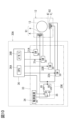
- FIG. 1 is a side cross-sectional view of a flow control valve according to a first embodiment of the present disclosure.
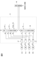
- FIG. 2 is a circuit diagram of the control device.
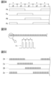
- FIG. 3 is a conceptual diagram of the excitation pattern.
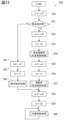
- FIG. 4 is a flowchart of the program.
- FIG. 5A is a conceptual diagram of an excitation pattern
- FIG. 5B is a conceptual diagram of a current control pulse signal
- FIG. 5C is a conceptual diagram of an on/off control signal.
- FIG. 6 is a block diagram of the control circuit.
- FIG. 7 is a block diagram of the control circuit.
- FIG. 8 is a block diagram of the origin setting unit.
- FIG. 9 is a block diagram of the position control unit.
- FIG. 10 is a circuit diagram of a control device according to a second embodiment.
- FIG. 11 is a flowchart of the program.
- FIG. 12 is a flowchart of a program according to the third embodiment.
- FIG. 13 is
- a valve device 10 according to a first embodiment of the present disclosure will be described with reference to Figures 1 to 9.
- the valve device 10 includes a flow control valve 11 as an electrically-driven device, and a control device 30A that controls the flow control valve 11.
- a motor 12 that is the drive source of the flow control valve 11 is, for example, a stepping motor, and has a male screw portion 14N and a female screw portion 20N that screw together on a central shaft 14 of a rotor 13 and a base portion 20 that rotatably supports the central shaft 14.
- a valve body 18, which will be described below, moves linearly as the rotor 13 rotates.
- a central hole 14A is formed at one end of the central shaft 14, into which the base end of a needle-shaped valve body 18 is fitted in a slidable but non-removable manner.
- a compression coil spring 18S housed within the central hole 14A biases the valve body 18 in the direction protruding from the central shaft 14.
- the base portion 20 is formed with a first hole 21A that extends coaxially with the central shaft 14, and a second hole 21B that communicates with the first hole 21A from the side, and an L-shaped flow path 21 is formed through the first hole 21A and the second hole 21B, allowing fluid to pass through.
- the first hole 21A is also formed with a valve hole 22 by narrowing a portion away from the second hole 21B.
- the valve body 18 moves linearly toward and away from the valve hole 22, changing the opening of the valve hole 22 and changing the flow rate of the fluid passing through the flow path 21. When the valve body 18 comes into contact with a valve seat 23, which is part of the inner surface of the valve hole 22, the valve hole 22 is closed.
- a spiral guide 19G which is made of a wire wound in a spiral shape, is fixed to the end of the central shaft 14 opposite the valve body 18 so as to be rotatable together with the central shaft 14.
- a stopper 19A which is made of a wire wound in a spiral shape with a larger diameter than the spiral guide 19G and shorter than the spiral guide 19G, is screwed onto the outer surface of the spiral guide 19G.
- a pair of stopper abutment parts 19S1, 19S2 are provided on both ends of the spiral guide 19G, and the stopper 19A abuts against the pair of stopper abutment parts 19S1, 19S2 to prevent it from coming off the spiral guide 19G.
- a rotation restriction bar 90A extends parallel to the central shaft 14 from one end of the rotor case 90 that houses the rotor 13 of the motor 12, and is disposed to the side of the spiral guide 19G, with a part of the stopper 19A abutting against the rotation restriction bar 90A.
- the rotation limiting mechanism 19K which includes the screw guide 19G, the stopper 19A, and the rotation restriction bar 90A, moves the stopper 19A linearly along the rotation restriction bar 90A as the rotor 13 rotates.
- the stopper 19A abuts against one of the stopper abutment portions 19S1, and the rotor 13 is positioned at one end of the rotatable range.
- the stopper 19A abuts against the other stopper abutment portion 19S2, and the rotor 13 is positioned at the other end of the rotatable range of the rotor 13.
- the rotatable range of the rotor 13 is stored in the memory 36B, which will be described later, as the maximum rotatable angle ⁇ max of the rotor 13.
- one end position of the rotatable range of the rotor 13, which is positioned by the stopper abutment portion 19S1 is set as the origin position for controlling the rotational position of the rotor 13 (i.e., for controlling the position of the motor 12) by the control device 30A described below. Also, at one end position of the rotor 13, i.e., the origin position, the valve body 18 abuts against the valve seat 23, and the compression coil spring 18S is in a slightly deflected state.
- the stopper abutment portion 19S1 that positions the rotor 13 at the origin position is provided inside the motor 12, but it may be provided outside the motor 12.
- the rotor 13 may be positioned at the origin position by the valve body 18 abutting against the valve seat 23 as a stopper.
- the valve body 18 is fixed to the central shaft 14 so that it cannot slide.
- the valve body 18 when the rotor 13 is placed at the origin position, the valve body 18 abuts against the valve seat 23 to fully close the valve hole 22, but when the rotor 13 is placed at the origin position, the valve body 18 may be slightly separated from the valve seat 23 to allow a small amount of fluid to pass through the valve hole 22.
- the control device 30A includes a drive circuit 33 for driving the motor 12, and a control circuit 36 for controlling the drive circuit 33.
- the drive circuit 33 the configuration of the motor 12 described above will be explained in more detail.
- the motor 12 is a claw-pole stepping motor having a permanent magnet 13M (see FIG. 1) in the rotor 13 and two-phase coils 91, 92 in the stator 93.
- the drive circuit 33 is wired to the coils 91 and 92 in, for example, a unipolar type, and has four switches 31A, 31a, 32B, and 32b, with one coil 91 being divided into coils A and a, and the other coil 92 being divided into coils B and b.
- the switches 31A, 31a, 32B, and 32b correspond one-to-one to the coils A, a, B, and b, and when any switch is turned on, a drive current is passed through the corresponding coil.
- the control circuit 36 includes a CPU 36A and a memory 36B, which is a computer-readable storage medium that stores information.
- An excitation pattern P for rotating the rotor 13 is stored in the memory 36B, an example of which is shown in FIG. 3.
- the excitation pattern P is composed of excitation patterns PA, Pa, PB, and Pb for the coils A, a, B, and b, and in the figure, the horizontal axis represents time and the number of steps.
- one rotation of the electrical angle of the rotor 13 is divided into four steps ST, and each time the step ST is switched in the direction of the time axis in FIG.
- step ST is switched in the opposite direction to the direction of the time axis in FIG. 3, and the rotor 13 is rotated and driven in the valve opening direction.
- the execution time of each step ST of the excitation pattern (hereinafter referred to as the "step width") can be arbitrarily changed, thereby arbitrarily changing the rotation speed and rotation acceleration of the rotor 13.
- the number of steps constituting the excitation pattern can be arbitrarily changed, thereby arbitrarily changing the rotation angle of the rotor 13.
- the memory 36B stores the program PG1 shown in FIG. 4.
- This program PG1 is executed, for example, when the control device 30A is powered on.
- the program PG1 is executed, first, the target rotation speed ⁇ x is set to a first rotation speed ⁇ 1 that has been set in advance (S11), and the target rotation acceleration ⁇ x is set to a rotation acceleration speed ⁇ 0 that has been set in advance (S12).
- a preset first drive current I1 is set as the target drive current Ix to be applied to the coils A, a, B, and b (S13).
- the target drive current Ix is used to control the drive current when driving the motor 12 in the origin setting process (S14) described below, and since this control is performed by PWM control, the first drive current I1 set as the target drive current Ix and the second drive current I2 described below are set at a duty ratio.
- the second drive current I2 is set to 100%, and the first drive current I1 is set to a smaller duty ratio. More specifically, the first drive current I1 is set to a value equivalent to the actual measured value of the minimum drive current required for the rotor 13 to rotate against frictional resistance, etc., for example.
- the origin setting process (S14) is executed.
- the origin setting excitation patterns PA, Pa, PB, Pb (see FIG. 5A) for rotating the rotor 13 in the valve closing direction by the target rotation angle ⁇ x obtained by adding the previously set additional rotation angle ⁇ a to the maximum rotatable angle ⁇ max are generated, and a current control pulse signal Y1 with a constant period t sufficiently smaller than the step width T of the origin setting excitation patterns PA, Pa, PB, Pb is generated (see FIG. 5B).
- the step length of each of the origin setting excitation patterns PA, Pa, PB, Pb is set to the length at which the rotor 13 is rotated at the aforementioned target rotation speed ⁇ x and target rotation acceleration ⁇ x, and the duty ratio of the fine pulse signal is set to the duty ratio of the aforementioned first target drive current Ix.
- the origin setting excitation patterns PA, Pa, PB, Pb are stepped, and only when the origin setting excitation patterns PA, Pa, PB, Pb are in the ON state, the current control pulse signal Y1 is output as the ON/OFF control signals ZA, Za, ZB, Zb (see FIG. 5C) for the switches 31A, 31a, 32B, 32b.
- the sound generated when the motor 12 repeatedly steps out and back out may be louder than the sound generated when the rotor 13 is operating without stepping out.
- the drive current passed through the motor 12 (specifically, coils A, a, B, b) in the origin setting process (S14) is PWM controlled to be a drive current with the duty ratio of the current control pulse signal Y1 described above, and is kept smaller than the drive current passed through the motor 12 in the position control process (S17) described next, and the output torque of the motor 12 is also kept low. This reduces the sound caused by the motor 12 stepping out and back out during the origin setting process (S14).
- the excitation state of coils A, a, B, and b is maintained at the excitation state of the final step.
- the rotational position of rotor 13 at this time is set as the origin position.
- the current rotational position of rotor 13 is updated and stored in memory 36B as the "number of steps away from the origin position.” This allows the origin position to be identified from the current rotational position updated and stored in memory 36B. In other words, the origin position is set by storing the current rotational position of rotor 13 in memory 36B.
- the target rotation speed ⁇ x is set to a second rotation speed ⁇ 2 that is greater than the first rotation speed ⁇ 1 (S15), and the target drive current Ix is set to a second drive current I2 that is greater than the first drive current I1 (S16).
- the second drive current I2 is set to, for example, 100%, when the second drive current I2 is set to the target drive current Ix, PWM control of the drive current of the motor 12 is not actually performed.
- the position control process (S17) is executed.
- the control device 30A waits until command data is given from outside the control device 30A.
- the command data is given, for example, as a target valve opening degree or a target flow rate of the flow control valve 11.
- the memory 36B also stores a data table that associates the command data with the target rotational position of the rotor 13. Then, in the position control process (S17), when command data is given, the target rotational position corresponding to the command data is determined based on the data table.
- excitation patterns PA, Pa, PB, Pb for rotating the rotor 13 to the target rotational position at the target rotational speed ⁇ x and the target rotational acceleration ⁇ x are given to each switch 31A, 31a, 32B, 32b as on-off control signals ZA, Za, ZB, Zb.
- the motor 12 is driven with a larger drive current and at a faster rotation speed than during the origin setting process, and the flow control valve 11 reaches the target valve opening according to the command data. Then, the position control process (S17) is executed every time command data is received, and flow control is performed by the flow control valve 11.
- a stepping motor has the characteristic that the lower the rotation speed of the rotor 13, the greater the output torque.
- the output torque is smaller during origin setting processing, when the rotation speed of the rotor 13 is lower than during position control processing.
- the CPU 36A When executing the above program PG1, the CPU 36A functions as the speed setting unit 41, acceleration setting unit 42, current setting unit 43, rotation angle setting unit 44, first pulse signal generating unit 45, second pulse signal generating unit 46, AND circuit 47, execution control unit 49, etc., shown in the block diagram of FIG. 6.
- the speed setting unit 41 sets the first or second rotation speed ⁇ 1, ⁇ 2 to the target rotation speed ⁇ x
- the acceleration setting unit 42 sets the rotation acceleration ⁇ 0 to the target rotation acceleration ⁇ x.
- the rotation angle setting unit 44 determines the target rotation angle ⁇ x from command data from the outside and a data table.
- the execution control unit 49 determines whether to give the first pulse signal generating unit 45 the target rotation angle ⁇ x determined by the rotation angle setting unit 44 or the target rotation angle ⁇ x determined from the maximum rotatable angle ⁇ max and the additional rotation angle ⁇ a.
- the current setting unit 43 sets the target drive current Ix to either the first drive current I1 or the second drive current I2.
- the first pulse signal generating unit 45 acquires data on the target rotation speed ⁇ x, the target rotation acceleration ⁇ x, and the target rotation angle ⁇ x, generates excitation pattern pulse signals XA, Xa, XB, and Xb for setting the origin, and outputs them separately to the multiple AND circuits 47.
- the first pulse signal generating unit 45 generates excitation pattern pulse signals XA, Xa, XB, and Xb based on command data, and outputs them separately to the multiple AND circuits 47.
- the second pulse signal generating unit 46 acquires the target drive current Ix, generates a current control pulse signal Y1 with a duty ratio according to the target drive current Ix, and outputs it to the multiple AND circuits 47.
- the multiple AND circuits 47 then perform AND processing on the excitation pattern pulse signals XA, Xa, XB, and Xb and the current control pulse signal Y1 to generate on/off control signals ZA, Za, ZB, and Zb, and output them to the switches 31A, 31a, 32B, and 32b.
- the first pulse signal generating unit 45 when the first pulse signal generating unit 45 receives the target rotation angle ⁇ x determined from the command data, it becomes a position control unit 52 for performing position control, and when the first pulse signal generating unit 45 receives the target rotation angle ⁇ x determined from the maximum rotatable angle ⁇ max and the additional rotation angle ⁇ a, it becomes an origin setting unit 51 for performing an origin setting process. Also, when performing position control, the duty ratio of PWM control becomes 100%, and since PWM control is not actually performed, the CPU 36A when executing the above program PG1 can also be shown in the block diagrams of Figures 7 to 9.
- the drive current to the motor 12 in the origin setting process (S14) is changed so that it is smaller than the drive current to the motor 12 in the position control process (S17), thereby reducing the noise during the origin setting process compared to the conventional case in which the motor 12 is driven with the same drive current during the position control process and the origin setting process.
- the drive current to the motor 12 in the origin setting process (S14) is set to the minimum required magnitude for rotating the rotor 13, the noise during the origin setting process can be minimized.
- the rotation speed of the motor 12 in the origin setting process (S14) is slower than the rotation speed of the motor 12 in the position control process (S17), this also reduces the noise during the origin setting process.
- the configuration of this embodiment reduces the noise generated during the origin setting process compared to the conventional method in which the motor 12 is driven with the same drive current and the same rotational speed during the position control process and the origin setting process, thereby meeting the demand for quietness.
- the drive current to the motor 12 in the origin setting process (S14) is actually measured and determined for each flow control valve 11 in order to set the minimum required magnitude, but if the drive current to the motor 12 in the origin setting process (S14) is smaller than the drive current to the motor 12 in the position control process (S17), the drive current to the motor 12 in the origin setting process (S14) may be determined uniformly for multiple flow control valves 11 without actually measuring. Also, in this embodiment, the rotation speed of the motor 12 when performing the origin setting process (S14) is slower than the rotation speed of the motor 12 when performing the position control process (S17), but the rotation speed of the motor 12 may be the same in the origin setting process (S14) and the position control process (S17).
- FIG. 10 and FIG. 11 This embodiment is shown in FIG. 10 and FIG. 11, and differs from the first embodiment in the configuration of a drive circuit 33 of a control device 30A and in a program PG2.
- the terminals of the coils A, a, B, and b that are not connected to the corresponding switches 31A, 31a, 32B, and 32b are commonly connected from the power supply 34, and a selection switch 35 and first and second resistors R1 and R2 as current reducing elements are connected between the common connection part and the power supply 34.
- the selection switch 35 selectively connects the first and second resistors R1 and R2 between the power supply 34 and the coils A, a, B, and b.
- the first resistor R1 has a larger resistance value than the second resistor R2, and the current that can pass through is narrowed. In other words, the drive current flowing through the coils A, a, B, and b is smaller when the first resistor R1 is connected to the power supply 34 than when the second resistor R2 is connected to the power supply 34.
- the selection switch 35 is set so that the first resistor R1 is connected to the power supply device 34 (S20). Then, in the origin setting process (S14), the current control pulse signal Y1 is not generated, and the origin setting excitation patterns PA, Pa, PB, Pb (see FIG. 5A) are applied to the switches 31A, 31a, 32B, 32b as on/off control signals ZA, Za, ZB, Zb. Also, when the origin setting process (S14) is completed, instead of step S16 of the program PG1 of the first embodiment, the selection switch 35 is switched so that the second resistor R2 is connected to the power supply device 34 (S21).
- the current setting unit 35K is composed of the selection switch 35 and the first and second resistors R1 and R2, and similar to the configuration of the first embodiment, the sound generated during the origin setting process is reduced compared to the conventional configuration, making it possible to meet the demands for high quietness.
- the output voltage of the power supply device 34 may be switched between the first and second output voltages.
- FIG. 12 and 13 This embodiment is shown in Figures 12 and 13, and the program PG3 is different from that of the first embodiment.
- the program PG3 is executed immediately after the power supply to the control device 30A is turned on, and is interrupted and terminated at the timing when a predetermined time (e.g., 12 hours, 24 hours, etc.) has elapsed since the power supply was turned on, and is executed from the beginning.
- a predetermined time e.g., 12 hours, 24 hours, etc.
- the information on the current position of the rotor 13 which is updated and stored in the memory 36B, is reset (i.e., erased) when the power supply to the control device 30A is stopped, but is maintained without being reset when the interruption of the program PG3 is ended.
- a preset value ⁇ 0 is set for the target rotation acceleration ⁇ x (S30). Then, it is checked whether the origin setting process has been completed (S31). Specifically, for example, it is checked whether the origin setting process has been completed by checking whether information on the current position of the rotor 13 is stored in memory 36B.
- the first rotation speed ⁇ 1 is set as the target rotation speed ⁇ x (S41), and the first drive current I1 is set as the target drive current Ix (S42), and then the same origin setting process (S43) as the origin setting process (S14) described in the first embodiment is performed.
- the second rotation speed ⁇ 2 is set to the target rotation speed ⁇ x (S32), the second drive current I2 is set to the target drive current Ix (S33), and then the position control process for returning to the origin (S34) is performed.
- the first rotation speed ⁇ 1 is set to the target rotation speed ⁇ x (S35), the first drive current I1 is set to the target drive current Ix (S36), and then the origin setting process for updating (S37) is performed.
- the first rotation speed ⁇ 1 is smaller than the second rotation speed ⁇ 2, and the first drive current I1 is smaller than the second drive current I2. This is the same as in the first embodiment.
- the same process as the position control process (S17) described in the first embodiment is performed to move the rotor 13 to the origin position.
- the origin setting process for updating (S37) is the same as the origin setting process (S14) described in the first embodiment except that the target rotation angle ⁇ x for rotating the rotor 13 in the valve closing direction is set to an additional rotation angle ⁇ a.
- the second rotation speed ⁇ 2 is set to the target rotation speed ⁇ x (S38), and the second drive current I2 is set to the target drive current Ix (S39), and then the same position control process (S40) as the position control process (S17) described in the first embodiment is performed.
- CPU 36A When executing step S31 of program PG3, CPU 36A functions as discrimination unit 48 in the block diagram shown in FIG. 13, and checks whether there is information on the current position of rotor 13 to be updated and stored in memory 36B.
- discrimination unit 48 determines that there is information on the current position, the discrimination result is received by execution control unit 49, which controls whether first pulse signal generation unit 45 functions as origin setting unit 51 or position control unit 52.
- the configuration of this embodiment makes it possible to reliably move the rotor 13 to the origin position before performing the origin setting process, even if a large resistance is encountered during the process of moving the rotor 13 from a position away from the origin position to the origin position. More specifically, for example, when a fluid is flowing through the flow path 21 in the flow control valve 11, it is assumed that the valve body 18 will encounter a large fluid resistance before moving to the origin position, and in such a case, the configuration of this embodiment is effective.
- the target rotation speed ⁇ x may be fixed to a constant value.
- the electrically-powered device having the motor 12 controlled by the control device 30A is the flow control valve 11, but is not limited to this and may be, for example, a printer, a toy, or the like.
- the motor 12 in the above embodiment was a PM type stepping motor with a permanent magnet 13M in the rotor 13, but is not limited to this.
- it may be a variable reluctance type with a gear-shaped iron core in the rotor 13, or a hybrid type in which both a permanent magnet and a gear-shaped iron core are used in the rotor 13.
- the motor 12 in the above embodiment was also a claw-pole type stepping motor with multiple phase coils 91, 92 arranged in the direction of the rotation axis on the stator side, but it may also be a structure with multiple teeth arranged in the circumferential direction on the stator side, with coils wound around each tooth.
- the motor does not have to be a stepping motor, and may be, for example, a servo motor with a resolver as a rotation sensor.
- the drive circuit 33 that drives the motor 12 is not limited to the unipolar wiring illustrated in the above embodiment, but may be bipolar.
- the excitation pattern was full-step excitation in which the voltage applied to the coils 91 and 92 was constant, but it may be half-step excitation or micro-step excitation in which the applied voltage is divided into multiple steps. Furthermore, it was multi-layer excitation in which multiple phase coils were excited simultaneously, but it may be single-layer excitation.
- the drive current to the motor 12 may be changed between the origin setting process and the position control process by performing PWM control as in the above embodiment, or it may be changed by means other than the PWM control described in the second embodiment.
- the rotational acceleration is constant between the origin setting process and the position control process, but the rotational acceleration may be different.
- a control device (30A) configured to perform an origin setting process (S14, S37, S43) for controlling a motor (12) to set an origin position of the motor (12) so that a movable part (19S1) of an electric device (11) using a motor (12) as a driving source is further pressed against a stopper (19A) while in contact with the stopper (19A), and a position control process (S17, S34, S40) for controlling the rotational position of the motor (12) relative to the origin position, the control device (30A) including a current setting unit (35K, 43) configured to change the drive current to the motor (12) in the origin setting process (S14, S37, S43) so that it is smaller than the drive current to the motor (12) in the position control process (S17, S34, S40).
- the control device (30A) configured to perform a preliminary position control process (S34) for matching the rotational position of the motor (12) to the origin position before the origin setting process (S14, S37, S43) is performed.
- the control device (30A) includes: a discrimination unit (48) configured to discriminate whether the origin position has been set or not; and an execution control unit (49) configured to, if the origin position has been set, perform a preliminary position control process (S34) to match the rotational position of the motor (12) with the origin position before the origin setting process (S37) is performed, while, if the origin position has not been set, control the execution of the preliminary position control process (S34) so that the preliminary position control process (S34) is not performed before the origin setting process (S43).
- a discrimination unit (48) configured to discriminate whether the origin position has been set or not
- an execution control unit (49) configured to, if the origin position has been set, perform a preliminary position control process (S34) to match the rotational position of the motor (12) with the origin position before the origin setting process (S37) is performed, while, if the origin position has not been set, control the execution of the preliminary position control process (S34) so that the preliminary position control process (S34) is not
- control device (30A) according to any one of features 1 to 3, further comprising a speed setting unit (41) configured to make the rotational speed of the motor (12) in the origin setting process (S14, S37, S43) smaller than the rotational speed of the motor (12) in the position control process (S17, S34, S40).
- the motor (12) is provided with a rotation limiting mechanism (19K) that limits the rotatable range of the rotor to multiple rotations, and the stopper (19A) is provided as part of the rotation limiting mechanism (19K).
- the programs (PG1 to PG3) cause a computer (36A) of a control device (30A) for an electric device (11) using a motor (12) as a drive source to function as an origin setting unit (51) configured to control the motor (12) of the control device (30A) to set an origin position of the motor (12) so that a movable part (19S1) of the electric device (11) is further pressed against a stopper (19A) while in contact with the stopper (19A), a position control unit (52) configured to control the rotational position of the motor (12) relative to the origin position, and a current setting unit (35K, 43) configured to change the drive current so that the drive current when the origin setting unit (51) controls the motor (12) is smaller than the drive current when the position control unit (52) controls the motor (12).
- an origin setting unit (51) configured to control the motor (12) of the control device (30A) to set an origin position of the motor (12) so that a movable part (19S1) of the electric device (11) is further pressed against a stopper (19A) while
- the program (PG3) described in feature 10 causes the computer (36A) to function as an execution control unit (49) configured to control the start-up of the position control unit (52) so that the position control unit (52) is started before the start-up of the origin setting unit (51) to match the rotational position of the motor (12) to the origin position.
- the program (PG3) described in feature 10 causes the computer (36A) to function as a discrimination unit (48) configured to discriminate whether the origin position has been set or not, and an execution control unit (49) configured to, if the origin position has been set, start the position control unit (52) before starting the origin setting unit (51) to make the rotational position of the motor (12) coincide with the origin position, while, if the origin position has not been set, control the start of the position control unit (52) so that the position control unit (52) is not started before starting the origin setting unit (51).
- a control method that performs an origin setting process (S14, S37, S43) for setting an origin position of the motor (12) by controlling the motor (12) so that a movable part (19S1) of an electric device (11) using a motor (12) as a drive source is further pressed against a stopper (19A) while in contact with the stopper, and a position control process (S17, S34, S40) for controlling the rotational position of the motor (12) relative to the origin position, the control method changing a drive current to the motor (12) in the origin setting process (S14, S37, S43) so that the drive current to the motor (12) is smaller than the drive current to the motor (12) in the position control process (S17, S34, S40).
- a control method according to any one of features 16 to 18, in which a first drive current (I1), which is the minimum drive current required to rotate the rotor of the motor (12), is actually measured and stored, and in the origin setting process (S14), the first drive current (I1) is applied to the motor (12).
- a first drive current (I1) which is the minimum drive current required to rotate the rotor of the motor (12)
- S14 origin setting process
- the control device of feature 1 the program of feature 10, the storage medium of feature 15, and the control method of feature 16, the drive current to the motor in the origin setting process is changed so that it is smaller than the drive current to the motor in the position control process, thereby reducing the noise during the origin setting process compared to the conventional method in which the motor was driven with the same drive current during the position control process and the origin setting process.
- the valve device of feature 9 which controls a flow control valve with this control device, can meet the demand for quietness when used in an air conditioning system.
- control device of features 2 and 3 the program of features 11 and 12, and the control method of features 17 and 18 allow the robot to reliably move to the origin position and then perform the origin setting process, even if a large resistance is applied during the movement from a position away from the origin position to the origin position.
- the rotation speed of the motor in the origin setting process is lower than the rotation speed of the motor in the position control process, so that the sound generated during the origin setting process is reduced compared to the conventional method in which the motor was driven at the same rotation speed during the position control process and the origin setting process.
- the program of feature 14, and the control method of feature 20 if the rotation speed of the motor in the origin setting process is made the same as or faster than the rotation speed of the motor in the position control process, the origin setting process can be performed quickly.
- the drive current to the motor in the origin setting process is set to an individual value for each electric device, so it is possible to accommodate the drive current to the motor that varies from one electric device to another.
- the origin setting process can be performed with the minimum drive current required to drive the motor of each electric device, and the noise during the origin setting process can be kept to a minimum.
- Valve device 11 Flow control valve (electric device) 12 Motor 14S Origin setting process 16S Position control process 18 Valve body 19A Stopper 19K Rotation limiting mechanism 23 Valve seat 30A Control device 35K, 43 Current setting section 36A CPU (computer) 36B memory 41 speed setting section 43 current setting section 48 discrimination section 49 execution control section 51 origin setting section 52 position control section PG1 to PG3 programs
Landscapes
- Engineering & Computer Science (AREA)
- Power Engineering (AREA)
- Control Of Stepping Motors (AREA)
Priority Applications (3)
| Application Number | Priority Date | Filing Date | Title |
|---|---|---|---|
| CN202380077711.6A CN120188383A (zh) | 2023-05-30 | 2023-05-30 | 控制装置、阀装置、程序、存储程序的存储介质以及控制方法 |
| JP2025523722A JPWO2024247083A1 (https=) | 2023-05-30 | 2023-05-30 | |
| PCT/JP2023/020025 WO2024247083A1 (ja) | 2023-05-30 | 2023-05-30 | 制御装置、弁装置、プログラム、プログラムを記憶する記憶媒体、及び、制御方法 |
Applications Claiming Priority (1)
| Application Number | Priority Date | Filing Date | Title |
|---|---|---|---|
| PCT/JP2023/020025 WO2024247083A1 (ja) | 2023-05-30 | 2023-05-30 | 制御装置、弁装置、プログラム、プログラムを記憶する記憶媒体、及び、制御方法 |
Publications (1)
| Publication Number | Publication Date |
|---|---|
| WO2024247083A1 true WO2024247083A1 (ja) | 2024-12-05 |
Family
ID=93656971
Family Applications (1)
| Application Number | Title | Priority Date | Filing Date |
|---|---|---|---|
| PCT/JP2023/020025 Ceased WO2024247083A1 (ja) | 2023-05-30 | 2023-05-30 | 制御装置、弁装置、プログラム、プログラムを記憶する記憶媒体、及び、制御方法 |
Country Status (3)
| Country | Link |
|---|---|
| JP (1) | JPWO2024247083A1 (https=) |
| CN (1) | CN120188383A (https=) |
| WO (1) | WO2024247083A1 (https=) |
Citations (10)
| Publication number | Priority date | Publication date | Assignee | Title |
|---|---|---|---|---|
| JPH08223991A (ja) | 1995-02-09 | 1996-08-30 | Unisia Jecs Corp | ステッピングモータの駆動方法 |
| JPH09117194A (ja) | 1995-10-17 | 1997-05-02 | Unisia Jecs Corp | ステッピングモータの駆動方法 |
| JP2004234806A (ja) | 2003-01-31 | 2004-08-19 | Toshiba Corp | ヘッドアンロード制御方法及びディスク記憶装置 |
| JP2005141878A (ja) | 2003-11-10 | 2005-06-02 | Ricoh Co Ltd | 光ディスク装置における光ピックアップ送り装置、光ピックアップ送り方法、そのプログラム及び情報記録媒体 |
| JP2008101815A (ja) | 2006-10-18 | 2008-05-01 | Matsushita Electric Ind Co Ltd | 冷蔵庫 |
| JP2009166598A (ja) | 2008-01-15 | 2009-07-30 | Toyota Motor Corp | 伝達比可変操舵装置 |
| WO2019146744A1 (ja) * | 2018-01-25 | 2019-08-01 | 株式会社デンソー | モータ制御装置、統合弁装置及び熱交換器 |
| JP2019170142A (ja) * | 2018-03-26 | 2019-10-03 | 株式会社デンソー | モータ制御装置、統合弁装置及び熱交換器 |
| WO2021200204A1 (ja) * | 2020-04-01 | 2021-10-07 | 株式会社デンソー | モータ制御装置 |
| JP2022141089A (ja) | 2021-03-15 | 2022-09-29 | 株式会社テージーケー | 電動弁制御装置 |
-
2023
- 2023-05-30 JP JP2025523722A patent/JPWO2024247083A1/ja active Pending
- 2023-05-30 CN CN202380077711.6A patent/CN120188383A/zh active Pending
- 2023-05-30 WO PCT/JP2023/020025 patent/WO2024247083A1/ja not_active Ceased
Patent Citations (10)
| Publication number | Priority date | Publication date | Assignee | Title |
|---|---|---|---|---|
| JPH08223991A (ja) | 1995-02-09 | 1996-08-30 | Unisia Jecs Corp | ステッピングモータの駆動方法 |
| JPH09117194A (ja) | 1995-10-17 | 1997-05-02 | Unisia Jecs Corp | ステッピングモータの駆動方法 |
| JP2004234806A (ja) | 2003-01-31 | 2004-08-19 | Toshiba Corp | ヘッドアンロード制御方法及びディスク記憶装置 |
| JP2005141878A (ja) | 2003-11-10 | 2005-06-02 | Ricoh Co Ltd | 光ディスク装置における光ピックアップ送り装置、光ピックアップ送り方法、そのプログラム及び情報記録媒体 |
| JP2008101815A (ja) | 2006-10-18 | 2008-05-01 | Matsushita Electric Ind Co Ltd | 冷蔵庫 |
| JP2009166598A (ja) | 2008-01-15 | 2009-07-30 | Toyota Motor Corp | 伝達比可変操舵装置 |
| WO2019146744A1 (ja) * | 2018-01-25 | 2019-08-01 | 株式会社デンソー | モータ制御装置、統合弁装置及び熱交換器 |
| JP2019170142A (ja) * | 2018-03-26 | 2019-10-03 | 株式会社デンソー | モータ制御装置、統合弁装置及び熱交換器 |
| WO2021200204A1 (ja) * | 2020-04-01 | 2021-10-07 | 株式会社デンソー | モータ制御装置 |
| JP2022141089A (ja) | 2021-03-15 | 2022-09-29 | 株式会社テージーケー | 電動弁制御装置 |
Also Published As
| Publication number | Publication date |
|---|---|
| JPWO2024247083A1 (https=) | 2024-12-05 |
| CN120188383A (zh) | 2025-06-20 |
Similar Documents
| Publication | Publication Date | Title |
|---|---|---|
| JP4987119B2 (ja) | ブラシレスモータ装置及び制御装置 | |
| US10844952B2 (en) | Shift range control apparatus | |
| JP6351834B2 (ja) | アクチュエータの制御装置、アクチュエータ、バルブ駆動装置およびアクチュエータの異常検知方法 | |
| JP2007311174A (ja) | 節度装置 | |
| WO2017179336A1 (ja) | シフトレンジ制御装置 | |
| JP2000041372A (ja) | 直流トルクモ―タ、およびこれを用いた駆動制御装置、スロットル弁制御装置 | |
| WO2024247083A1 (ja) | 制御装置、弁装置、プログラム、プログラムを記憶する記憶媒体、及び、制御方法 | |
| JP2005091496A (ja) | セクタ駆動機構 | |
| JP6648063B2 (ja) | ステッピングモータの制御装置及びステッピングモータの制御方法 | |
| JP6205219B2 (ja) | 指針式メータ装置 | |
| JP2016178203A (ja) | ソレノイド装置 | |
| JP6585651B2 (ja) | モータ制御装置及びステッピングモータの制御方法 | |
| JP6583124B2 (ja) | シフトレンジ制御装置 | |
| JP2022150878A (ja) | シフト装置 | |
| WO2024247084A1 (ja) | 制御装置、弁装置、空調システム、プログラム、プログラムを記憶する記憶媒体、及び、劣化検査方法 | |
| JP5058527B2 (ja) | ステッピングモータの駆動装置 | |
| JP2585003B2 (ja) | マルチプログラムシヤツタ | |
| US20210180690A1 (en) | Shift range control device | |
| JP2000050607A (ja) | 回転位置制御装置 | |
| WO2025032818A1 (ja) | 駆動制御装置及び弁装置 | |
| WO2017082072A1 (ja) | 電気機械装置、モータ制御装置及び回転制御方法 | |
| JP2021072691A (ja) | 電動アクチュエータおよびモータ駆動制御方法 | |
| JP5394642B2 (ja) | ステッピングモータ制御装置、アクチュエータ装置、及び車両用ヘッドランプ装置 | |
| JP2005299466A (ja) | バルブリフト調整装置 | |
| JP2024137324A (ja) | 電動弁制御装置および電動弁装置、ならびに、電動弁の制御方法 |
Legal Events
| Date | Code | Title | Description |
|---|---|---|---|
| 121 | Ep: the epo has been informed by wipo that ep was designated in this application |
Ref document number: 23939562 Country of ref document: EP Kind code of ref document: A1 |
|
| WWE | Wipo information: entry into national phase |
Ref document number: 2025523722 Country of ref document: JP |
|
| WWE | Wipo information: entry into national phase |
Ref document number: CN2023800777116 Country of ref document: CN Ref document number: 202380077711.6 Country of ref document: CN |
|
| WWP | Wipo information: published in national office |
Ref document number: 202380077711.6 Country of ref document: CN |
|
| NENP | Non-entry into the national phase |
Ref country code: DE |