WO2024241784A1 - 積層体及びフィルターエレメント - Google Patents
積層体及びフィルターエレメント Download PDFInfo
- Publication number
- WO2024241784A1 WO2024241784A1 PCT/JP2024/015434 JP2024015434W WO2024241784A1 WO 2024241784 A1 WO2024241784 A1 WO 2024241784A1 JP 2024015434 W JP2024015434 W JP 2024015434W WO 2024241784 A1 WO2024241784 A1 WO 2024241784A1
- Authority
- WO
- WIPO (PCT)
- Prior art keywords
- laminate
- support
- membrane
- less
- bubble point
- Prior art date
- Legal status (The legal status is an assumption and is not a legal conclusion. Google has not performed a legal analysis and makes no representation as to the accuracy of the status listed.)
- Ceased
Links
Images


Classifications
-
- B—PERFORMING OPERATIONS; TRANSPORTING
- B01—PHYSICAL OR CHEMICAL PROCESSES OR APPARATUS IN GENERAL
- B01D—SEPARATION
- B01D65/00—Accessories or auxiliary operations, in general, for separation processes or apparatus using semi-permeable membranes
- B01D65/10—Testing of membranes or membrane apparatus; Detecting or repairing leaks
-
- B—PERFORMING OPERATIONS; TRANSPORTING
- B01—PHYSICAL OR CHEMICAL PROCESSES OR APPARATUS IN GENERAL
- B01D—SEPARATION
- B01D69/00—Semi-permeable membranes for separation processes or apparatus characterised by their form, structure or properties; Manufacturing processes specially adapted therefor
-
- B—PERFORMING OPERATIONS; TRANSPORTING
- B01—PHYSICAL OR CHEMICAL PROCESSES OR APPARATUS IN GENERAL
- B01D—SEPARATION
- B01D69/00—Semi-permeable membranes for separation processes or apparatus characterised by their form, structure or properties; Manufacturing processes specially adapted therefor
- B01D69/02—Semi-permeable membranes for separation processes or apparatus characterised by their form, structure or properties; Manufacturing processes specially adapted therefor characterised by their properties
-
- B—PERFORMING OPERATIONS; TRANSPORTING
- B01—PHYSICAL OR CHEMICAL PROCESSES OR APPARATUS IN GENERAL
- B01D—SEPARATION
- B01D69/00—Semi-permeable membranes for separation processes or apparatus characterised by their form, structure or properties; Manufacturing processes specially adapted therefor
- B01D69/10—Supported membranes; Membrane supports
-
- B—PERFORMING OPERATIONS; TRANSPORTING
- B01—PHYSICAL OR CHEMICAL PROCESSES OR APPARATUS IN GENERAL
- B01D—SEPARATION
- B01D69/00—Semi-permeable membranes for separation processes or apparatus characterised by their form, structure or properties; Manufacturing processes specially adapted therefor
- B01D69/12—Composite membranes; Ultra-thin membranes
-
- B—PERFORMING OPERATIONS; TRANSPORTING
- B01—PHYSICAL OR CHEMICAL PROCESSES OR APPARATUS IN GENERAL
- B01D—SEPARATION
- B01D69/00—Semi-permeable membranes for separation processes or apparatus characterised by their form, structure or properties; Manufacturing processes specially adapted therefor
- B01D69/12—Composite membranes; Ultra-thin membranes
- B01D69/1213—Laminated layers
-
- B—PERFORMING OPERATIONS; TRANSPORTING
- B01—PHYSICAL OR CHEMICAL PROCESSES OR APPARATUS IN GENERAL
- B01D—SEPARATION
- B01D71/00—Semi-permeable membranes for separation processes or apparatus characterised by the material; Manufacturing processes specially adapted therefor
- B01D71/06—Organic material
- B01D71/30—Polyalkenyl halides
- B01D71/32—Polyalkenyl halides containing fluorine atoms
- B01D71/36—Polytetrafluoroethylene
-
- B—PERFORMING OPERATIONS; TRANSPORTING
- B32—LAYERED PRODUCTS
- B32B—LAYERED PRODUCTS, i.e. PRODUCTS BUILT-UP OF STRATA OF FLAT OR NON-FLAT, e.g. CELLULAR OR HONEYCOMB, FORM
- B32B27/00—Layered products comprising a layer of synthetic resin
- B32B27/30—Layered products comprising a layer of synthetic resin comprising vinyl (co)polymers; comprising acrylic (co)polymers
-
- B—PERFORMING OPERATIONS; TRANSPORTING
- B32—LAYERED PRODUCTS
- B32B—LAYERED PRODUCTS, i.e. PRODUCTS BUILT-UP OF STRATA OF FLAT OR NON-FLAT, e.g. CELLULAR OR HONEYCOMB, FORM
- B32B27/00—Layered products comprising a layer of synthetic resin
- B32B27/32—Layered products comprising a layer of synthetic resin comprising polyolefins
- B32B27/322—Layered products comprising a layer of synthetic resin comprising polyolefins comprising halogenated polyolefins, e.g. PTFE
-
- B—PERFORMING OPERATIONS; TRANSPORTING
- B32—LAYERED PRODUCTS
- B32B—LAYERED PRODUCTS, i.e. PRODUCTS BUILT-UP OF STRATA OF FLAT OR NON-FLAT, e.g. CELLULAR OR HONEYCOMB, FORM
- B32B5/00—Layered products characterised by the non- homogeneity or physical structure, i.e. comprising a fibrous, filamentary, particulate or foam layer; Layered products characterised by having a layer differing constitutionally or physically in different parts
- B32B5/22—Layered products characterised by the non- homogeneity or physical structure, i.e. comprising a fibrous, filamentary, particulate or foam layer; Layered products characterised by having a layer differing constitutionally or physically in different parts characterised by the presence of two or more layers which are next to each other and are fibrous, filamentary, formed of particles or foamed
-
- C—CHEMISTRY; METALLURGY
- C08—ORGANIC MACROMOLECULAR COMPOUNDS; THEIR PREPARATION OR CHEMICAL WORKING-UP; COMPOSITIONS BASED THEREON
- C08J—WORKING-UP; GENERAL PROCESSES OF COMPOUNDING; AFTER-TREATMENT NOT COVERED BY SUBCLASSES C08B, C08C, C08F, C08G or C08H
- C08J9/00—Working-up of macromolecular substances to porous or cellular articles or materials; After-treatment thereof
-
- B—PERFORMING OPERATIONS; TRANSPORTING
- B01—PHYSICAL OR CHEMICAL PROCESSES OR APPARATUS IN GENERAL
- B01D—SEPARATION
- B01D2325/00—Details relating to properties of membranes
- B01D2325/02—Details relating to pores or porosity of the membranes
- B01D2325/0283—Pore size
-
- B—PERFORMING OPERATIONS; TRANSPORTING
- B01—PHYSICAL OR CHEMICAL PROCESSES OR APPARATUS IN GENERAL
- B01D—SEPARATION
- B01D2325/00—Details relating to properties of membranes
- B01D2325/22—Thermal or heat-resistance properties
Definitions
- This disclosure relates to a laminate and a filter element comprising the laminate.
- This application claims priority to Japanese Patent Application No. 2023-084101, filed on May 22, 2023. All contents of said Japanese patent application are incorporated herein by reference.
- Patent Documents 1 to 5 porous membranes containing polytetrafluoroethylene as a main component
- Patent Documents 4 and 5 laminates comprising said porous membranes have been used as precision filtration filters for dispersion media and substrates in the semiconductor-related field and the like.
- the laminate according to one embodiment of the present disclosure comprises: A laminate comprising a porous membrane,
- the porous membrane contains polytetrafluoroethylene as a main component,
- the laminate is in a sheet form,
- the average bubble point P1a of the laminate is 390 kPa or more; or
- the average bubble point P1b of the laminate is 780 kPa or more,
- the average bubble point P1a is measured by the bubble point method using liquid 1a,
- the surface tension of the 1a liquid is 13 mN/m
- the average bubble point P1b is measured by a bubble point method using liquid 1b,
- the surface tension of the 1b liquid is 21 mN/m
- the Gurley second of the laminate is 70 seconds or less, In a test in which the laminate is left standing in a thermostatic chamber at 120° C.
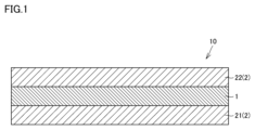
- FIG. 1 is a schematic enlarged cross-sectional view showing an example of a laminate according to an embodiment of the present disclosure.
- FIG. 2 is a schematic enlarged cross-sectional view showing another example of a laminate according to an embodiment of the present disclosure.
- FIG. 3 is a schematic enlarged cross-sectional view showing another example of a laminate according to an embodiment of the present disclosure.
- FIG. 4 is a schematic enlarged cross-sectional view showing still another example of a laminate according to an embodiment of the present disclosure.
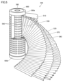
- FIG. 5 is a perspective view of a filter element according to one embodiment of the present disclosure.
- a laminate having a porous membrane is required to have a high average bubble point.
- the average bubble point is an index showing the difficulty of particles, etc. passing through. The higher the average bubble point, the more difficult it is for particles, etc. to pass through.
- the laminate when a laminate with a porous membrane is used as a pleated cartridge filter, the laminate is heat-set by folding it into pleats and then heating it.
- the thermal stability of the laminate is low (in other words, if it is prone to thermal shrinkage), it is likely to be difficult to process the cartridge, and the properties of the laminate (pore size and flow rate) are likely to change, so the laminate is required to have excellent thermal stability.
- Stretched polytetrafluoroethylene is inherently prone to shrinkage. By heating the stretched polytetrafluoroethylene in the sintering process, the polytetrafluoroethylene is melted, and the internal stress generated by the stretching is released.
- thermo stability By cooling and recrystallizing the stretched polytetrafluoroethylene, thermal stability is imparted to the stretched polytetrafluoroethylene. Therefore, a laminate with a porous membrane containing such polytetrafluoroethylene as a main component has excellent thermal stability due to the sintering process. In addition, excellent “thermal stability” here means that "shrinkage of the laminate with a porous membrane caused by heating" is unlikely to occur.
- the laminate with the porous film containing polytetrafluoroethylene as the main component has excellent thermal stability due to the above-mentioned sintering process, but it tends to have a low average bubble point and a low flow rate due to the expansion of pores and the decrease in porosity (in other words, the ratio of the volume of pores to the total volume of the porous film) caused by the aggregation of fibers in the porous film.
- the present disclosure therefore aims to provide a laminate that combines excellent thermal stability with a high average bubble point and a high filtrate flow rate, and a filter element that includes the laminate.
- a laminate according to one embodiment of the present disclosure A laminate comprising a porous membrane, The porous membrane contains polytetrafluoroethylene as a main component, The laminate is in a sheet form, The average bubble point P1a of the laminate is 390 kPa or more; or The average bubble point P1b of the laminate is 780 kPa or more, The average bubble point P1a is measured by a bubble point method using a 1a liquid, The surface tension of the first liquid is 13 mN/m; The average bubble point P1b is measured by a bubble point method using a 1b liquid, The surface tension of the first liquid is 21 mN/m; The Gurley second of the laminate is 70 seconds or less, In a test in which the laminate is left standing in a thermostatic chamber at 120° C.
- the present disclosure provides a laminate and a filter element including the laminate that have excellent thermal stability, a high average bubble point, and a high filtrate flow rate.
- the laminate has a maximum tensile strength S1 in the MD direction and a maximum tensile strength S2 in the TD direction,
- the maximum tensile strength S1 in the MD direction and the maximum tensile strength S2 in the TD direction may satisfy the relationship of Equation 3. 3.2 ⁇ S1/S2 ⁇ 5.0 Formula 3 This allows for the provision of a laminate and a filter element comprising the laminate that combines better thermal stability with a higher average bubble point and higher filtrate flow rates.
- the laminate further comprises a support film,
- the support membrane is porous,
- the support film may contain polytetrafluoroethylene as a main component, which provides a laminate and a filter element including the laminate that have a combination of better thermal stability, a higher average bubble point, and a higher filtrate flow rate.
- the support film comprises a first support film and a second support film, the porous membrane and the second support membrane are disposed in this order on the first support membrane;
- Each of the first support film and the second support film may be a uniaxially stretched support film, thereby providing a laminate and a filter element including the laminate that have a combination of better thermal stability, a higher average bubble point, and a higher filtrate flow rate.
- the support film includes a first support film, a second support film, a third support film, and a fourth support film; the second support membrane, the porous membrane, the third support membrane, and the fourth support membrane are disposed in this order on the first support membrane;
- Each of the second support film and the third support film is a biaxially stretched support film,
- Each of the first support film and the fourth support film may be a uniaxially stretched support film, thereby providing a laminate and a filter element including the laminate that have a combination of better thermal stability, a higher average bubble point, and a higher filtrate flow rate.
- a filter element according to one embodiment of the present disclosure comprises a laminate according to any one of [1] to [5] above.
- the present disclosure provides a filter element having a laminate that combines excellent thermal stability with a high average bubble point and a high filtrate flow rate.
- this embodiment is not limited thereto.
- an expression in the form of "A to B” means the upper and lower limits of a range (i.e., A or more and B or less).
- a or more and B or less the upper and lower limits of a range
- FIG. 1 A laminate 10 according to an embodiment of the present disclosure will be described with reference to FIGS. 1 to 4.
- FIG. One embodiment of the present disclosure (hereinafter also referred to as "the present embodiment") is A laminate 10 comprising a porous membrane 1,
- the porous membrane 1 contains polytetrafluoroethylene as a main component,
- the laminate 10 is in the form of a sheet.
- the average bubble point P1a of the laminate 10 is 390 kPa or more, or the average bubble point P1b of the laminate 10 is 780 kPa or more.
- the laminate 10 can have a high average bubble point.
- the average bubble point is measured by the bubble point method, in which a specific liquid is used.
- the numerical value of the average bubble point varies depending on the surface tension of the specific liquid.
- P1a measured by the bubble point method using "1a liquid”
- P1b measured by the bubble point method using “1b liquid”
- P2a and “P2b” described below, as well as “P3a” and “P3b” described below are defined.
- the Gurley second of the laminate 10 is 70 seconds or less.
- the laminate 10 can exhibit a high filtrate flow rate.
- a length X in an MD (Machine Direction) direction of the laminate 10 before the test and a length X′ in the MD direction of the laminate 10 after the test satisfy the relationship of Formula 1
- the length Y of the laminate 10 in the TD (Transverse Direction) direction before the test and the length Y′ of the laminate 10 in the TD direction after the test satisfy the relationship of Equation 2.
- the laminate 10 includes a porous membrane 1.
- the laminate 10 may further include a support membrane 2.
- the support membrane 2 functions as a protective material for the porous membrane 1, thereby improving the capture performance of the laminate 10, and increasing the mechanical strength and lifespan of the laminate 10.
- the support membrane 2 may be, for example, a form (form 1) in which the porous membrane 1 and the second support membrane 22 are arranged on the first support membrane 21 in this order.
- the support membrane 2 may be a form (form 2) in which the first support membrane 21, the second support membrane 22, the third support membrane 23, and the fourth support membrane 24 are arranged on the first support membrane 21 in this order.
- the porous membrane 1 may be composed of a first porous membrane and a second porous membrane
- the support membrane 2 may be composed of a first support membrane 21, a second support membrane 22, a third support membrane 23, a fourth support membrane 24, and a fifth support membrane 25, with the second support membrane 22, the first porous membrane, the third support membrane 23, the second porous membrane, the fourth support membrane 24, and the fifth support membrane 25 being arranged in this order on the first support membrane 21 (form 3).
- the porous membrane 1 may be composed of a first porous membrane, a second porous membrane, and a third porous membrane
- the support membrane 2 may be composed of a first support membrane 21, a second support membrane 22, a third support membrane 23, a fourth support membrane 24, a fifth support membrane 25, and a sixth support membrane 26, and the second support membrane 22, the first porous membrane, the third support membrane 23, the second porous membrane, the fourth support membrane 24, the third porous membrane, the fifth support membrane 25, and the sixth support membrane 26 may be arranged in this order on the first support membrane 21 (form 4).
- the support membrane 2 may be either a uniaxially stretched support membrane described later or a biaxially stretched support membrane described later.
- the laminate 10 is in the form of a sheet.
- "in the form of a sheet” means in the form of a thin plate.
- the thickness of the laminate 10 may be 0.010 mm or more and 0.200 mm or less. If the thickness is less than 0.010 mm, the strength of the laminate 10 tends to be insufficient. If the thickness is more than 0.200 mm, the pressure loss during permeation of the filtrate tends to be large.
- the lower limit of the thickness of the laminate 10 may be 0.010 mm or more, 0.013 mm or more, or 0.015 mm or more.
- the upper limit of the thickness of the laminate 10 may be 0.200 mm or less, 0.150 mm or less, or 0.100 mm or less.
- the thickness of the laminate 10 may be 0.013 mm or more and 0.150 mm or less, or 0.015 mm or more and 0.100 mm or less.
- the shape of the laminate 10 is long.
- the thickness of the laminate 10 can be determined in a manner similar to the measurement method for the "thickness of the porous membrane 1" described below, except that the measurement is performed on the laminate 10. It has been confirmed that similar results can be obtained when different measurement points are arbitrarily selected on the same laminate 10 and the above measurement is performed at those measurement points.
- the length X in the MD direction of the laminate 10 before the test of leaving the laminate 10 in a thermostatic chamber at 120° C. for 1 hour is not particularly limited as long as the relationship of Formula 1 is satisfied, but may be, for example, 0.010 m or more and 1.000 m or less, 0.020 m or more and 0.500 m or less, or 0.025 m or more and 0.250 m or less.
- the "MD direction" can be rephrased as the longitudinal direction.
- the length X of the laminate 10 in the MD direction can be determined by the following method. First, the laminate 10 is prepared before the test by placing it in a thermostatic chamber at 120°C for 1 hour. Next, the length of the laminate 10 in the MD direction is measured at any five points. Next, the average value of the lengths in the MD direction is calculated, thereby determining the length X of the laminate 10 in the MD direction.
- the length X' of the laminate 10 in the MD direction after a test in which the laminate 10 is left in a thermostatic chamber at 120°C for 1 hour is not particularly limited as long as the relationship in formula 1 is satisfied, but can be, for example, 0.010 m or more and 1.000 m or less, 0.020 m or more and 0.500 m or less, or 0.025 m or more and 0.250 m or less.
- the length X' of the laminate 10 in the MD direction can be determined in the same manner as the "length X of the laminate 10 in the MD direction," except that the measurement is performed on the laminate 10 after a test in which the laminate 10 is left in a thermostatic chamber at 120°C for 1 hour.
- the length Y of the laminate 10 in the TD direction before the test in which the laminate 10 is left in a thermostatic chamber at 120°C for 1 hour is not particularly limited as long as the relationship in formula 2 is satisfied, but can be, for example, 0.010 m or more and 1.000 m or less, 0.020 m or more and 0.500 m or less, or 0.025 m or more and 0.250 m or less.
- the "TD direction" of the laminate 10 is the direction perpendicular to the above-mentioned "MD direction” and the thickness direction of the laminate 10.
- the length Y of the laminate 10 in the TD direction can be determined by the following method. First, the laminate 10 is prepared before the test by placing it in a thermostatic chamber at 120°C for 1 hour. Next, the length of the laminate 10 in the TD direction is measured at any five points. Next, the average value of the TD lengths is calculated, thereby determining the length Y of the laminate 10 in the TD direction.
- the length Y' of the laminate 10 in the TD direction after a test in which the laminate 10 is left in a thermostatic chamber at 120°C for 1 hour is not particularly limited as long as the relationship in formula 2 is satisfied, but can be, for example, 0.010 m or more and 1.000 m or less, 0.020 m or more and 0.500 m or less, or 0.025 m or more and 0.250 m or less.
- the length Y' of the laminate 10 in the MD direction can be determined in the same manner as the "length Y of the laminate 10 in the TD direction," except that the measurement is performed on the laminate 10 after a test in which the laminate 10 is left in a thermostatic chamber at 120°C for 1 hour.
- the MD length X of the laminate 10 before the test and the MD length X' of the laminate 10 after the test satisfy the relationship of Formula 1
- the TD length Y of the laminate 10 before the test and the TD length Y' of the laminate 10 after the test satisfy the relationship of Formula 2.
- /Y ⁇ 0.05 Formula 2 This allows the laminate 10 to have excellent thermal stability without sacrificing high average bubble point and high filtrate flow rate.
- /X” may be 0.09 or less, 0.08 or less, or 0.07 or less.
- /X” may be 0.01 or more, 0.02 or more, or 0.03 or more.
- /X” may be 0.01 or more and 0.10 or less, 0.02 or more and 0.09 or less, or 0.03 or more and 0.08 or less.
- /Y may be 0.09 or less, 0.08 or less, or 0.07 or less.
- /Y may be 0.01 or more, 0.02 or more, or 0.03 or more.
- /Y may be 0.01 or more and 0.10 or less, 0.02 or more and 0.09 or less, or 0.03 or more and 0.08 or less.
- the density of the laminate 10 may be 0.10 g/cm 3 or more and 2.00 g/cm 3 or less. When the density is less than 0.10 g/cm 3 , the strength of the laminate 10 tends to be insufficient. When the density is more than 2.00 g/cm 3 , the transmission efficiency of the laminate 10 tends to decrease.
- the lower limit of the density of the laminate 10 may be 0.10 g/cm 3 or more, 0.13 g/cm 3 or more, or 0.15 g/cm 3 or more.
- the upper limit of the density of the laminate 10 may be 2.00 g/cm 3 or less, 1.70 g/cm 3 or less, or 1.50 g/cm 3 or less.
- the density of the laminate 10 may be 0.13 g/cm 3 or more and 1.70 g/cm 3 or less, or 0.15 g/cm 3 or more and 1.50 g/cm 3 or less.
- the density of the laminate 10 can be determined in a manner similar to the measurement method for the "density of the porous membrane 1" described below, except that the measurement is performed on the "laminate 10." It has been confirmed that similar results can be obtained when a different measurement range is arbitrarily selected for the same laminate 10 and the above measurement is performed in that measurement range.
- the basis weight of the laminate 10 may be 0.005 mg/mm 2 or more and 0.100 mg/mm 2 or less. When the basis weight of the laminate 10 is less than 0.005 mg/mm 2 , the strength of the laminate 10 tends to be insufficient. When the basis weight of the laminate 10 is more than 0.100 mg/mm 2 , the permeability efficiency of the laminate 10 tends to decrease.
- the lower limit of the basis weight of the laminate 10 may be 0.005 mg/mm 2 or more, 0.007 mg/mm 2 or more, or 0.008 mg/mm 2 or more.
- the upper limit of the basis weight of the laminate 10 may be 0.100 mg/mm 2 or less, 0.080 mg/mm 2 or less, or 0.060 mg/mm 2 or less.
- the basis weight of the laminate 10 may be 0.007 mg/mm 2 or more and 0.080 mg/mm 2 or less, or may be 0.008 mg/mm 2 or more and 0.060 mg/mm 2 or less.
- the basis weight of the laminate 10 can be determined in a manner similar to the measurement method for the "basis weight of the porous membrane 1" described below, except that the measurement is performed on the "laminate 10." It has been confirmed that similar results can be obtained when a different measurement range is arbitrarily selected for the same laminate 10 and the above measurement is performed in that measurement range.
- the average bubble point P1a of the laminate 10 is 390 kPa or more, and the average bubble point P1b of the laminate 10 is 780 kPa or more.
- the average bubble point P1a is measured by a bubble point method using a 1a liquid, and the surface tension of the 1a liquid is 13 mN/m.
- the average bubble point P1b is measured by a bubble point method using a 1b liquid, and the surface tension of the 1b liquid is 21 mN/m.
- the laminate 10 can have a high average bubble point.
- the lower limit of the average bubble point P1a of the laminate 10 may be 400 kPa or more, 410 kPa or more, or 420 kPa or more.
- the upper limit of the average bubble point P1a of the laminate 10 may be 900 kPa or less, 890 kPa or less, or 880 kPa or less.
- the average bubble point P1a of the laminate 10 may be 390 kPa or more and 900 kPa or less, 400 kPa or more and 890 kPa or less, or 410 kPa or more and 880 kPa or less.
- the average bubble point P1a of the laminate 10 is determined by the following method. That is, except that the measurement is performed on the "laminated body 10", it is determined by a method similar to the measurement method of the "average bubble point P2a of the porous membrane 1" described below.
- the lower limit of the average bubble point P1b of the laminate 10 may be 790 kPa or more, 800 kPa or more, or 810 kPa or more.
- the upper limit of the average bubble point P1b of the laminate 10 may be 1400 kPa or less, 1390 kPa or less, or 1380 kPa or less.
- the average bubble point P1b of the laminate 10 may be 780 kPa or more and 1400 kPa or less, 790 kPa or more and 1390 kPa or less, or 800 kPa or more and 1380 kPa or less.
- the average bubble point P1b of the laminate 10 is determined by the following method. That is, except that the measurement is performed on the "laminated body 10", it is determined by a method similar to the measurement method of the "average bubble point P2b of the porous membrane 1" described below.
- the Gurley second of the laminate 10 is 70 seconds or less. This allows the flow rate of the filtrate to be increased, thereby increasing the permeation efficiency.
- the lower limit of the Gurley second of the laminate 10 may be 1 second or more, 3 seconds or more, or 5 seconds or more.
- the upper limit of the Gurley second of the laminate 10 may be 45 seconds or less, 40 seconds or less, or 35 seconds or less.
- the Gurley second of the laminate 10 may be 1 second or more and 68 seconds or less, 3 seconds or more and 66 seconds or less, or 5 seconds or more and 40 seconds or less.
- the Gurley second of the laminate 10 is determined by the following method. That is, except that the measurement is performed on the "laminated body 10", it can be determined by the same method as the measurement method of the "Gurley second of the porous membrane 1" described later.
- the mean flow pore size of the laminate 10 can be determined in a manner similar to the measurement method for the "mean flow pore size of the porous membrane 1" described below, except that the measurement is performed on the "laminate 10.”
- polytetrafluoroethylene is a polymer of tetrafluoroethylene, and is a concept that includes a homopolymer of tetrafluoroethylene and a modified product of the "monopolymer of tetrafluoroethylene".
- the modified product is a tetrafluoroethylene-hexafluoropropylene copolymer (in other words, a perfluoroethylene propene copolymer.
- FEP tetrafluoroethylene-perfluoroalkyl vinyl ether copolymer
- PFA tetrafluoroethylene-perfluoroalkyl vinyl ether copolymer
- ETFE ethylene-tetrafluoroethylene copolymer
- the modified product may contain 0.1 mol % or less of hexafluoropropylene (HFP), perfluoro(alkyl vinyl ether) (FVE), or the like.
- HFP hexafluoropropylene
- FVE perfluoro(alkyl vinyl ether)
- the content of polytetrafluoroethylene can be specified based on the absorbance at 4.25 ⁇ m of "-CF 2 -” which indicates tetrafluoroethylene (TFE), the absorbance at 10.18 ⁇ m of "-CH 3 group” which indicates FEP, and the absorbance at 10.07 ⁇ m of "CF 3 O- group” which indicates PFA. It has been confirmed that the same results can be obtained even if different measurement ranges are arbitrarily selected in the same porous membrane 1.
- the density of the porous membrane 1 may be 0.05 g/cm 3 or more and 2.00 g/cm 3 or less. When the density is less than 0.05 g/cm 3 , the strength of the porous membrane 1 tends to be insufficient. When the density is more than 2.00 g/cm 3 , the permeation efficiency of the porous membrane 1 tends to decrease.
- the lower limit of the density of the porous membrane 1 may be 0.05 g/cm 3 or more, 0.10 g/cm 3 or more, or 0.15 g/cm 3 or more.
- the upper limit of the density of the porous membrane 1 may be 2.00 g/cm 3 or less, 1.70 g/cm 3 or less, or 1.50 g/cm 3 or less.
- the density of the porous membrane 1 may be 0.10 g/cm 3 or more and 1.70 g/cm 3 or less, or 0.15 g/cm 3 or more and 1.50 g/cm 3 or less.
- the basis weight of the porous membrane 1 may be 0.002 mg/mm 2 or more and 0.100 mg/mm 2 or less. When the basis weight of the porous membrane 1 is less than 0.002 mg/mm 2 , the strength of the porous membrane 1 tends to be insufficient. When the basis weight of the porous membrane 1 is more than 0.100 mg/mm 2 , the permeation efficiency of the porous membrane 1 tends to decrease.
- the lower limit of the basis weight of the porous membrane 1 may be 0.002 mg/mm 2 or more, 0.003 mg/mm 2 or more, or 0.004 mg/mm 2 or more.
- the upper limit of the basis weight of the porous membrane 1 may be 0.100 mg/mm 2 or less, 0.080 mg/mm 2 or less, or 0.060 mg/mm 2 or less.
- the basis weight of the porous membrane 1 may be 0.003 mg/mm 2 or more and 0.080 mg/mm 2 or less, or may be 0.004 mg/mm 2 or more and 0.060 mg/mm 2 or less.
- the average bubble point P2a of the porous membrane 1 is measured by the bubble point method using the 1a liquid, and the surface tension of the 1a liquid is 13 mN/m. More specifically, the average bubble point of the porous membrane 1 is determined by the following method. First, for a dry porous membrane 1, the differential pressure applied to the porous membrane 1 and the air flow rate passing through the porous membrane 1 are measured based on the bubble point method (ASTM F316-86, JIS K3832). Next, in a coordinate system with the differential pressure on the horizontal axis and the air flow rate on the vertical axis, a first curve is obtained showing the relationship between the differential pressure and the numerical value obtained by dividing the air flow rate by 2.
- the porous membrane 1 is immersed in "Opteon SF70" (trademark), a hydrofluoroolefin (1a liquid) manufactured by Mitsui-Chemours Fluoroproducts, Inc., for about 5 minutes at about 25°C, and then removed from the hydrofluoroolefin (1a liquid) to obtain a porous membrane 1 wet with hydrofluoroolefin (1a liquid).
- the differential pressure applied to the porous membrane 1 and the air flow rate passing through the porous membrane 1 are measured based on the bubble point method.
- the average bubble point P2b is measured by the bubble point method using the 1b liquid, and the surface tension of the 1b liquid is 21 mN/m. More specifically, in the porous membrane 1, the average bubble point P2b is determined in a manner similar to the measurement method for P2a, except that isopropyl alcohol (1b liquid) manufactured by Fujifilm Wako Pure Chemical Industries, Ltd. is used instead of the 1a liquid.
- each of the second support film and the third support film may be a biaxially stretched support film
- each of the first support film and the fourth support film may be a uniaxially stretched support film.
- each of the second support membrane, the third support membrane, and the fourth support membrane may be a biaxially stretched support membrane, and each of the first support membrane and the fifth support membrane may be a uniaxially stretched support membrane.
- each of the second support membrane, the third support membrane, the fourth support membrane, and the fifth support membrane may be a biaxially stretched support membrane
- each of the first support membrane and the sixth support membrane may be a uniaxially stretched support membrane.
- the support film 2 is a uniaxially stretched support film
- the support film 2 is a uniaxially stretched support film
- the maximum tensile strength S5 in the MD direction and the maximum tensile strength S6 in the TD direction satisfy the relationship of Equation 5.
- the maximum tensile strength S3 in the MD direction and the maximum tensile strength S4 in the TD direction can be determined by a method similar to the method for measuring the maximum tensile strength S1 in the MD direction and the maximum tensile strength S2 in the TD direction of the laminate 10, except that the measurements are performed on a biaxially stretched support film.
- the density of the support film 2 may be 0.10 g/cm 3 or more and 2.00 g/cm 3 or less. When the density is less than 0.10 g/cm 3 , the strength of the laminate 10 tends to be insufficient. When the density is more than 2.00 g/cm 3 , the permeability efficiency of the laminate 10 tends to decrease.
- the lower limit of the density of the support film 2 may be 0.10 g/cm 3 or more, 0.13 g/cm 3 or more, or 0.15 g/cm 3 or more.
- the upper limit of the density of the support film 2 may be 2.00 g/cm 3 or less, 1.70 g/cm 3 or less, or 1.50 g/cm 3 or less.
- the density of the support film 2 may be 0.13 g/cm 3 or more and 1.70 g/cm 3 or less, or 0.15 g/cm 3 or more and 1.50 g/cm 3 or less.
- the densities of the first to sixth support membranes may be in the ranges described above.
- the density of the support membrane 2 can be determined in a manner similar to the measurement method for the "density of the porous membrane 1" described above, except that the measurement is performed on the "support membrane 2.” It has been confirmed that similar results can be obtained by arbitrarily selecting a different measurement range for the same support membrane 2 and performing the above measurement in that measurement range.
- the basis weight of the support film 2 may be 0.005 mg/mm 2 or more and 0.100 mg/mm 2 or less. When the basis weight of the support film 2 is less than 0.005 mg/mm 2 , the strength of the laminate 10 tends to be insufficient. When the basis weight of the support film 2 is more than 0.100 mg/mm 2 , the permeability efficiency of the laminate 10 tends to decrease.
- the lower limit of the basis weight of the support film 2 may be 0.005 mg/mm 2 or more, 0.006 mg/mm 2 or more, or 0.007 mg/mm 2 or more.
- the average bubble point P3a of the support film 2 may be 5 kPa or more and 400 kPa or less, or the average bubble point P3b of the support film 2 may be 5 kPa or more and 800 kPa or less. This allows the laminate 10 to have a higher average bubble point.
- the lower limit of the average bubble point P3a of the support film 2 may be 5 kPa or more, 7 kPa or more, or 10 kPa or more.
- the upper limit of the average bubble point P3a of the support film 2 may be 400 kPa or less, 350 kPa or less, or 300 kPa or less.
- the average bubble point P3a of the support film 2 is measured by the bubble point method using the 1a liquid, and the surface tension of the 1a liquid is 13 mN/m. More specifically, the average bubble point P3a of the laminate 10 is determined by the following method. That is, it is determined by the same method as the measurement method of the "average bubble point P2a of the porous film 1" described above, except that the measurement is performed on the "support film 2".
- the Gurley second of the support membrane 2 may be 0.5 seconds or more and 60 seconds or less. This allows the flow rate of the filtrate to be increased, and therefore the permeation efficiency to be increased.
- the lower limit of the Gurley second of the support membrane 2 may be 0.5 seconds or more, 0.7 seconds or more, or 1.0 second or more.
- the upper limit of the Gurley second of the support membrane 2 may be 60 seconds or less, 50 seconds or less, or 40 seconds or less.
- the Gurley second of the support membrane 2 may be 0.7 seconds or more and 50 seconds or less, or 1.0 second or more and 40 seconds or less.
- the Gurley seconds of the first to sixth support membranes may be in the above range.
- the Gurley second of the support membrane 2 is determined by the following method. That is, except that the measurement is performed on the "support membrane 2", it can be determined in the same manner as the measurement method of the "Gurley second of the porous membrane 1" described above.
- the mean flow pore size of the support membrane 2 may be 45 nm or more and 600 nm or less. This allows the laminate 10 to have both excellent strength and excellent permeation efficiency.
- the lower limit of the mean flow pore size may be 45 nm or more, 50 nm or more, or 55 nm or more.
- the upper limit of the mean flow pore size may be 600 nm or less, 550 nm or less, or 500 nm or less.
- the mean flow pore size may be 50 nm or more and 550 nm or less, or 55 nm or more and 500 nm or less.
- the mean flow pore size of the first to sixth support membranes may be in the above range.
- the laminates of samples 1-1 to 1-4 correspond to examples.
- the laminates of samples 1-101 to 1-103 correspond to comparative examples.
- the laminates of samples 1-1 to 1-4 have a higher average bubble point than the laminate of sample 1-102.
- a Gurley second of the laminate of 70 seconds or less means that the laminate exhibits a high filtrate flow rate.
- the laminates of samples 1-1 to 1-4 exhibit high filtrate flow rates.
- the laminates of samples 1-1 to 1-4 have exceptionally superior thermal stability compared to the laminates of samples 1-101 and 103.
- the laminates of samples 1-1 to 1-4 exhibit exceptionally excellent effects, combining superior thermal stability with a high average bubble point and exhibiting a high filtrate flow rate.
- Step 1-1-b> The kneaded material was extruded into a sheet under the conditions shown in Table 9 to obtain a precursor of a sheet-shaped molded product. The precursor was then rolled with a calendar roll to obtain a sheet having an average thickness of 100 mm. As a result, a sheet-like molded product having the properties as shown in Table 9 was obtained.
- the above kneaded material was extruded into a sheet under the conditions shown in Table 10 to obtain a precursor of a sheet-shaped molded product.
- the precursor was rolled with a calendar roll to obtain a sheet-shaped molded product having an average thickness as shown in Table 10.
- the above molded body was stretched under the conditions shown in Table 10 to obtain an extended body.
- the stretched body was subjected to heat treatment under the conditions shown in Table 10 to obtain a porous first support film.
- the second support film was prepared for samples 2-1 to 2-4 and samples 2-101 to 2-103 as follows.
- a mixture was obtained by mixing "PTFE fine powder C (second heat of fusion 26.0 J/g, molecular weight about 5 million)" which is a polytetrafluoroethylene powder and "Supersol FP-25” (trademark) which is a solvent naphtha (liquid lubricant) manufactured by Idemitsu Oil Co., Ltd., in the parts by mass shown in Table 11.
- the mixture was compression molded into a block shape using a compression molding machine, to obtain a kneaded product.
- the stretched body was subjected to heat treatment under the conditions shown in Table 11 to obtain a porous second support film.
- the above molded body was stretched under the conditions shown in Table 13 to obtain an extended body.
- ⁇ Second step> A sheet-like laminate was obtained by laminating the first support membrane, the second support membrane, the porous membrane, the third support membrane, and the fourth support membrane in this order under the conditions shown in Table 14.
- the laminates of samples 2-1 to 2-4 correspond to examples.
- the laminates of samples 2-101 to 2-103 correspond to comparative examples.
- the laminates of samples 2-1 to 2-4 have a higher average bubble point than the laminate of sample 2-102.
- a Gurley second of 70 seconds or less means that the laminate exhibits a high filtrate flow rate.
- the laminates of samples 2-1 to 2-4 show a higher filtrate flow rate than the laminate of sample 2-103.
- the ratio of the absolute value of the difference between X' and X to X being 10% or less, and the ratio of the absolute value of the difference between Y' and Y to Y being 5% or less means that the thermal stability of the laminate is excellent.
- the laminates of samples 2-1 to 2-4 have exceptionally superior thermal stability compared to the laminates of samples 2-101 to 2-103.
- the laminates of samples 2-1 to 2-4 exhibit exceptionally excellent effects, combining superior thermal stability with a high average bubble point and exhibiting a high filtrate flow rate.
- Example 1 and Example 2 only a laminate in which "the support membrane is composed of a first support membrane and a second support membrane, and a porous membrane and the second support membrane are arranged in this order on the first support membrane" and a laminate in which "the support membrane is composed of a first support membrane, a second support membrane, a third support membrane, and a fourth support membrane, and the second support membrane, the porous membrane, the third support membrane, and the fourth support membrane are arranged in this order on the first support membrane" are shown.
- the Gurley second of the laminate is 70 seconds or less, and in a test in which the laminate is left standing in a thermostatic chamber at 120°C for 1 hour, the MD length X of the laminate before the test and the MD length X' of the laminate after the test satisfy the relationship of the above formula 1, and the TD length Y of the laminate before the test and the TD length Y'
- the porous membrane is composed of a first porous membrane and a second porous membrane
- the support membrane is composed of a first support membrane, a second support membrane, a third support membrane, a fourth support membrane, and a fifth support membrane
- the second support membrane, the first porous membrane, the third support membrane, the second porous membrane, the fourth support membrane, and the fifth support membrane are arranged in this order on the first support membrane
- each of the second support membrane, the third support membrane, and the fourth support membrane is a biaxially stretched support membrane
- each of the first support membrane and the fifth support membrane is a uniaxially stretched support membrane.
- the porous membrane is composed of a first porous membrane, a second porous membrane, and a third porous membrane
- the support membrane is composed of a first support membrane, a second support membrane, a third support membrane, a fourth support membrane, a fifth support membrane, and a sixth support membrane
- the second support membrane, the first porous membrane, the third support membrane, the second porous membrane, the fourth support membrane, the third porous membrane, the fifth support membrane, and the sixth support membrane are arranged in this order on the first support membrane, and each of the second support membrane, the third support membrane, the fourth support membrane, and the fifth support membrane is a biaxially stretched support membrane, and each of the first support membrane and the sixth support membrane is a uniaxially stretched support membrane.
Landscapes
- Chemical & Material Sciences (AREA)
- Chemical Kinetics & Catalysis (AREA)
- Engineering & Computer Science (AREA)
- Materials Engineering (AREA)
- Health & Medical Sciences (AREA)
- Medicinal Chemistry (AREA)
- Polymers & Plastics (AREA)
- Organic Chemistry (AREA)
- Separation Using Semi-Permeable Membranes (AREA)
Priority Applications (3)
| Application Number | Priority Date | Filing Date | Title |
|---|---|---|---|
| CN202480033672.4A CN121240970A (zh) | 2023-05-22 | 2024-04-18 | 层叠体和过滤元件 |
| JP2025521881A JPWO2024241784A1 (https=) | 2023-05-22 | 2024-04-18 | |
| KR1020257038482A KR20260013939A (ko) | 2023-05-22 | 2024-04-18 | 적층체 및 필터 엘리먼트 |
Applications Claiming Priority (2)
| Application Number | Priority Date | Filing Date | Title |
|---|---|---|---|
| JP2023-084101 | 2023-05-22 | ||
| JP2023084101 | 2023-05-22 |
Publications (1)
| Publication Number | Publication Date |
|---|---|
| WO2024241784A1 true WO2024241784A1 (ja) | 2024-11-28 |
Family
ID=93589949
Family Applications (1)
| Application Number | Title | Priority Date | Filing Date |
|---|---|---|---|
| PCT/JP2024/015434 Ceased WO2024241784A1 (ja) | 2023-05-22 | 2024-04-18 | 積層体及びフィルターエレメント |
Country Status (5)
| Country | Link |
|---|---|
| JP (1) | JPWO2024241784A1 (https=) |
| KR (1) | KR20260013939A (https=) |
| CN (1) | CN121240970A (https=) |
| TW (1) | TW202500256A (https=) |
| WO (1) | WO2024241784A1 (https=) |
Citations (9)
| Publication number | Priority date | Publication date | Assignee | Title |
|---|---|---|---|---|
| JPH07278331A (ja) * | 1994-04-11 | 1995-10-24 | Sumitomo Electric Ind Ltd | ポリテトラフルオロエチレン多孔質体とその製造方法 |
| JP2011052175A (ja) * | 2009-09-04 | 2011-03-17 | Sumitomo Electric Fine Polymer Inc | ポリテトラフルオロエチレン多孔質膜、多孔質フッ素樹脂膜複合体及びそれらの製造方法 |
| JP2013527260A (ja) * | 2010-03-12 | 2013-06-27 | セルガード エルエルシー | 二軸配向細孔性膜、合成物、ならびに製造および使用の方法 |
| JP2015226877A (ja) * | 2014-05-30 | 2015-12-17 | 住友電工ファインポリマー株式会社 | 多孔質フィルタ |
| JP2016078305A (ja) * | 2014-10-15 | 2016-05-16 | 住友電気工業株式会社 | 多孔質積層体 |
| JP2016135602A (ja) * | 2013-02-15 | 2016-07-28 | ポール・コーポレーションPall Corporation | Ptfe膜を含む複合体 |
| JP2019135303A (ja) * | 2014-09-12 | 2019-08-15 | ダブリュ.エル.ゴア アンド アソシエイツ,インコーポレイティドW.L. Gore & Associates, Incorporated | 改良された機械及び熱特性を有する多孔性通気性ポリテトラフルオロエチレン複合材 |
| JP2020532422A (ja) * | 2017-11-28 | 2020-11-12 | エルジー・ケム・リミテッド | フッ素系樹脂多孔性膜の製造方法 |
| WO2023162368A1 (ja) * | 2022-02-28 | 2023-08-31 | 住友電工ファインポリマー株式会社 | 多孔質膜積層体 |
-
2024
- 2024-04-18 CN CN202480033672.4A patent/CN121240970A/zh active Pending
- 2024-04-18 KR KR1020257038482A patent/KR20260013939A/ko active Pending
- 2024-04-18 JP JP2025521881A patent/JPWO2024241784A1/ja active Pending
- 2024-04-18 WO PCT/JP2024/015434 patent/WO2024241784A1/ja not_active Ceased
- 2024-05-14 TW TW113117746A patent/TW202500256A/zh unknown
Patent Citations (9)
| Publication number | Priority date | Publication date | Assignee | Title |
|---|---|---|---|---|
| JPH07278331A (ja) * | 1994-04-11 | 1995-10-24 | Sumitomo Electric Ind Ltd | ポリテトラフルオロエチレン多孔質体とその製造方法 |
| JP2011052175A (ja) * | 2009-09-04 | 2011-03-17 | Sumitomo Electric Fine Polymer Inc | ポリテトラフルオロエチレン多孔質膜、多孔質フッ素樹脂膜複合体及びそれらの製造方法 |
| JP2013527260A (ja) * | 2010-03-12 | 2013-06-27 | セルガード エルエルシー | 二軸配向細孔性膜、合成物、ならびに製造および使用の方法 |
| JP2016135602A (ja) * | 2013-02-15 | 2016-07-28 | ポール・コーポレーションPall Corporation | Ptfe膜を含む複合体 |
| JP2015226877A (ja) * | 2014-05-30 | 2015-12-17 | 住友電工ファインポリマー株式会社 | 多孔質フィルタ |
| JP2019135303A (ja) * | 2014-09-12 | 2019-08-15 | ダブリュ.エル.ゴア アンド アソシエイツ,インコーポレイティドW.L. Gore & Associates, Incorporated | 改良された機械及び熱特性を有する多孔性通気性ポリテトラフルオロエチレン複合材 |
| JP2016078305A (ja) * | 2014-10-15 | 2016-05-16 | 住友電気工業株式会社 | 多孔質積層体 |
| JP2020532422A (ja) * | 2017-11-28 | 2020-11-12 | エルジー・ケム・リミテッド | フッ素系樹脂多孔性膜の製造方法 |
| WO2023162368A1 (ja) * | 2022-02-28 | 2023-08-31 | 住友電工ファインポリマー株式会社 | 多孔質膜積層体 |
Also Published As
| Publication number | Publication date |
|---|---|
| KR20260013939A (ko) | 2026-01-29 |
| TW202500256A (zh) | 2025-01-01 |
| CN121240970A (zh) | 2025-12-30 |
| JPWO2024241784A1 (https=) | 2024-11-28 |
Similar Documents
| Publication | Publication Date | Title |
|---|---|---|
| TWI482654B (zh) | A filter material having a porous film, a manufacturing method thereof, a filter bag and a filter unit | |
| EP3124093B1 (en) | Filter medium for air filter, filter pack, air filter unit, and method for manufacturing filter medium for air filter | |
| KR100459960B1 (ko) | 다공성폴리테트라플루오로에틸렌막,이의제조방법,시트형폴리테트라플루오로에틸렌성형품및공기여과재 | |
| TWI526243B (zh) | Porous multi - layer filter | |
| CA2031827C (en) | Process for producing multilayer polytetrafluoroethylene porous membrane | |
| KR101353726B1 (ko) | 폴리테트라플루오로에틸렌 다공질막의 제조 방법과 필터 여과재 및 필터 유닛 | |
| JP2022078151A (ja) | フッ素系樹脂多孔性膜の製造方法 | |
| CN103649189A (zh) | 聚四氟乙烯多孔膜及空气过滤器滤材 | |
| US20130087500A1 (en) | Crystalline polymer microporous membrane, production method thereof, and filtration filter | |
| EP4035763B1 (en) | Polytetrafluoroethylene porous film having high strength and small pore diameter | |
| WO2013005431A1 (ja) | ポリテトラフルオロエチレン多孔質膜の製造方法 | |
| JP2014042869A (ja) | 多孔質複層フィルター | |
| US11872531B2 (en) | Fluorine-based resin porous membrane and method for preparing the same | |
| WO2024241784A1 (ja) | 積層体及びフィルターエレメント | |
| KR20200020460A (ko) | 불소계 수지 다공성 막 | |
| TW202330747A (zh) | 多孔質膜及多孔質膜積層體 | |
| TW202335733A (zh) | 多孔質膜、多孔質膜積層體及多孔質膜之製造方法 | |
| WO2023162368A1 (ja) | 多孔質膜積層体 | |
| WO2024241783A1 (ja) | 多孔質膜、積層体、及びフィルターエレメント | |
| WO2024241782A1 (ja) | 多孔質膜、積層体、及びフィルターエレメント | |
| JPH08174738A (ja) | 多孔質四弗化エチレン樹脂積層体とその製造方法 | |
| KR20190040801A (ko) | 불소 수지 다공성 막의 제조 방법 및 불소 수지 다공성 막 | |
| WO2012124500A1 (ja) | 結晶性ポリマー微孔性膜及びその製造方法、並びに濾過用フィルタ | |
| JP2024171901A (ja) | 多孔質膜 | |
| JP2012192308A (ja) | 結晶性ポリマー微孔性膜及びその製造方法、並びに濾過用フィルタ及び濾過装置 |
Legal Events
| Date | Code | Title | Description |
|---|---|---|---|
| 121 | Ep: the epo has been informed by wipo that ep was designated in this application |
Ref document number: 24810792 Country of ref document: EP Kind code of ref document: A1 |
|
| ENP | Entry into the national phase |
Ref document number: 2025521881 Country of ref document: JP Kind code of ref document: A |
|
| WWE | Wipo information: entry into national phase |
Ref document number: 2025521881 Country of ref document: JP |
|
| NENP | Non-entry into the national phase |
Ref country code: DE |