WO2024237043A1 - 回転電機システムの制御装置及び制御プログラム - Google Patents
回転電機システムの制御装置及び制御プログラム Download PDFInfo
- Publication number
- WO2024237043A1 WO2024237043A1 PCT/JP2024/015930 JP2024015930W WO2024237043A1 WO 2024237043 A1 WO2024237043 A1 WO 2024237043A1 JP 2024015930 W JP2024015930 W JP 2024015930W WO 2024237043 A1 WO2024237043 A1 WO 2024237043A1
- Authority
- WO
- WIPO (PCT)
- Prior art keywords
- phase
- switch
- electric machine
- rotating electric
- current
- Prior art date
- Legal status (The legal status is an assumption and is not a legal conclusion. Google has not performed a legal analysis and makes no representation as to the accuracy of the status listed.)
- Pending
Links
Images


Classifications
-
- H—ELECTRICITY
- H02—GENERATION; CONVERSION OR DISTRIBUTION OF ELECTRIC POWER
- H02P—CONTROL OR REGULATION OF ELECTRIC MOTORS, ELECTRIC GENERATORS OR DYNAMO-ELECTRIC CONVERTERS; CONTROLLING TRANSFORMERS, REACTORS OR CHOKE COILS
- H02P27/00—Arrangements or methods for the control of AC motors characterised by the kind of supply voltage
- H02P27/04—Arrangements or methods for the control of AC motors characterised by the kind of supply voltage using variable-frequency supply voltage, e.g. inverter or converter supply voltage
- H02P27/06—Arrangements or methods for the control of AC motors characterised by the kind of supply voltage using variable-frequency supply voltage, e.g. inverter or converter supply voltage using DC to AC converters or inverters
-
- H—ELECTRICITY
- H02—GENERATION; CONVERSION OR DISTRIBUTION OF ELECTRIC POWER
- H02P—CONTROL OR REGULATION OF ELECTRIC MOTORS, ELECTRIC GENERATORS OR DYNAMO-ELECTRIC CONVERTERS; CONTROLLING TRANSFORMERS, REACTORS OR CHOKE COILS
- H02P29/00—Arrangements for regulating or controlling electric motors, appropriate for both AC and DC motors
- H02P29/60—Controlling or determining the temperature of the motor or of the drive
Definitions
- This disclosure relates to a control device and control program for a rotating electrical machine system.
- a control device for an inverter that electrically connects a battery to the windings that make up a rotating electric machine is known.
- a discharge control is performed by applying a d-axis voltage by switching control of the inverter to cause a d-axis current to flow through the rotating electric machine, and a charge control is performed by lowering the d-axis voltage following the discharge control to return electrical energy from the coil of the rotating electric machine to the battery, alternately and repeatedly. This generates Joule heat in the battery, raising the temperature of the battery.
- This disclosure was made in consideration of the above problems, and its main objective is to efficiently generate heat in a rotating electrical machine system.
- a control device that is applied to a rotating electric machine system including a rotating electric machine having a multi-phase winding and an inverter that adjusts a phase current of each phase in the winding by turning on and off a plurality of switches made of semiconductor switching elements, and controls the on and off of the switches in the inverter, comprising: a determination unit that determines whether or not there is a heat generation request in the rotating electrical machine system; a switch control unit that controls the switch when it is determined that there is a heat generation request so that a transition time of at least one of turning on and turning off the switch is longer than a transition time when there is no heat generation request; Equipped with.
- the transition time of at least one of the switches (semiconductor switching elements) when they are turned on and off is made longer than when there is no heat generation request. This allows each switch of the inverter to generate heat due to an increase in the amount of switching loss. As a result, heat can be generated efficiently in the rotating electric machine system.
- Heat generation means generating heat
- heat generation request means requesting the generation of heat
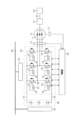
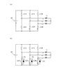
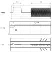
- FIG. 1 is an overall configuration diagram of a rotating electrical machine system.
- FIG. 2 is a diagram showing a configuration of a switch drive circuit;
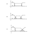
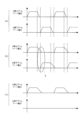
- FIG. 3 is a time chart showing changes in switch voltage Vsw and switch current Isw.
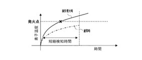
- FIG. 4 is a time chart showing the rise in element temperature when the switch is turned on;
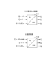
- FIG. 5 is a diagram showing the process of dq-UVW conversion.
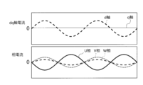
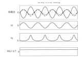
- FIG. 6 is a time chart showing current waveforms of the dq axis current and the phase current of each phase.
- FIG. 7 is a diagram showing a switching pattern when heat generation control is performed by energizing the d-axis.
- FIG. 8 is a diagram showing a switching pattern when heat generation control is performed by energizing the d-axis.
- FIG. 9 is a time chart showing changes in gate voltages of the upper and lower arm switches;
- FIG. 10 is a time chart showing an example of control of gate resistance switching in each phase;
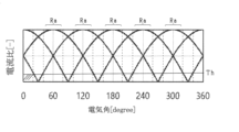
- FIG. 11 is a diagram showing the relationship between the electrical angle and the current ratio of each phase;
- FIG. 12 is a time chart showing switching control in three states with different modulation factors.
- FIG. 13 is a diagram showing the process of dq-UVW conversion.
- FIG. 14 is a time chart for specifically explaining the heat generation control by the d-axis current supply.
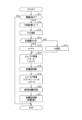
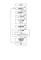
- FIG. 15 is a flowchart showing a procedure for heat generation control while the vehicle is stopped.
- FIG. 16 is a flowchart showing a procedure for heat generation control while the vehicle is traveling.
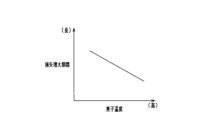
- FIG. 17 is a diagram showing the relationship between element temperature and the length of the loss increase period;
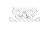
- FIG. 18 is a diagram showing the meshing of gears in a gear device;
- FIG. 19 is a time chart showing changes in various parameters when a q-axis torque is generated.
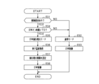
- FIG. 20 is a flowchart showing a procedure for heat generation control while the vehicle is stopped.
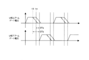
- FIG. 21 is a time chart showing changes in gate voltages of the upper and lower arm switches.
- FIG. 22 is a diagram showing a configuration for changing the dead time in response to a heat generation request.
- the rotating electric machine system according to an embodiment is mounted on an electric vehicle such as a battery electric vehicle (BEV) or a hybrid electric vehicle (HEV).
- BEV battery electric vehicle
- HEV hybrid electric vehicle
- the rotating electric machine system includes a rotating electric machine 10, an inverter 20 as a power converter, a battery 30 as a high-voltage power supply, and a control device 40.
- the rotating electric machine 10 is a brushless synchronous machine, and in this embodiment, it is a permanent magnet synchronous machine.
- the rotating electric machine 10 includes a rotor (not shown) and a three-phase (U-phase, V-phase, W-phase) coil 11 as a stator winding.
- the coil 11 is configured by star-connecting a U-phase coil, a V-phase coil, and a W-phase coil.
- the rotating electric machine 10 includes a rotation angle sensor 12 that detects the rotation angle (electrical angle) of the rotor, and a phase current sensor 13 that detects the phase current of each phase flowing through the coil 11. It is preferable that the phase current sensor 13 is provided for each of the three phases. However, the phase current sensor 13 may be provided for only two of the three phases.
- the rotating electric machine 10 is provided as a power source for driving the vehicle, and the wheels are rotated and driven by the rotation of the rotor.
- the rotation of the rotor of the rotating electric machine 10 is transmitted to the input shaft of the gear device 51, and the rotation of the output shaft of the gear device 51 is transmitted to the wheels 53 via the axle 52.
- the inverter 20 has a series connection of an upper arm switch 21 and a lower arm switch 22 for each phase.
- Each of the upper arm and lower arm switches 21, 22 is a semiconductor switching element, for example an N-channel MOSFET.
- the high potential terminal is the drain, and the low potential terminal is the source.
- a diode 23 is connected in inverse parallel to each of the switches 21, 22 (semiconductor switching elements) as a freewheel diode.
- the midpoint between the upper arm switch 21 and the lower arm switch 22 is connected to the end point of the coil 11 of the rotating electric machine 10.
- the semiconductor switching element may be an IGBT or the like.
- a drive circuit 24 is connected to the gates of each switch 21, 22, and the drive circuit 24 turns the switches 21, 22 on and off based on a drive command from the control device 40.
- the drive circuit 24 is provided with a short circuit detection unit 25 that detects the occurrence of a short circuit in each switch 21, 22 of the upper and lower arms.
- the short circuit detection unit 25 detects the flow of an overcurrent due to a short circuit in the upper and lower arms, and forcibly shuts off the switches 21, 22 upon detection of the overcurrent.
- Each switch 21, 22 is provided with an element temperature sensor 26 that detects the temperature of the semiconductor switching element.
- the battery 30 is a secondary battery such as a lithium ion battery or a nickel metal hydride battery.
- the battery 30 is, for example, a battery pack including a series connection of multiple battery cells.
- the drains of the upper arm switches 21 of each phase are connected to the positive terminal of the battery 30 via a high potential side path 31.
- the sources of the lower arm switches 22 of each phase are connected to the negative terminal of the battery 30 via a low potential side path 32.
- the inverter 20 and the battery 30 are provided with heat transfer units 61, 62, respectively, and these heat transfer units 61, 62 are connected to each other by a refrigerant passage 63 made of piping or the like.
- heat transfer unit 61 on the inverter 20 side heat transfer is performed between the switches 21, 22 of the inverter 20 and the refrigerant flowing through the refrigerant passage 63.
- heat transfer unit 62 on the battery 30 side heat transfer is performed between the battery 30 and the refrigerant flowing through the refrigerant passage 63.
- the refrigerant passage 63 is provided as a circulation path for circulating the refrigerant, and the refrigerant passage 63 is provided with a pump for circulating the refrigerant and a heat dissipation unit such as a radiator.
- the control device 40 is mainly composed of a microcomputer, which has a CPU.
- the functions provided by the microcomputer can be provided by software recorded in a physical memory device and a computer that executes the software, by software alone, by hardware alone, or by a combination of these.
- the microcomputer executes a program stored in a non-transitory tangible storage medium that serves as a storage unit provided in the microcomputer.
- the program includes programs for various types of arithmetic processing. When a program is executed, a method corresponding to the program is executed.
- the storage unit is, for example, a non-volatile memory.
- the programs stored in the storage unit can be updated via a network such as the Internet, such as OTA (Over The Air).
- the control device 40 receives detection signals from various sensors, such as the rotation angle sensor 12, phase current sensor 13, and element temperature sensor 26 described above. Based on the detection values received, the control device 40 performs switching control of the switches 21 and 22 that make up the inverter 20, in order to control the control amount (e.g., torque) of the rotating electric machine 10 to a command value.
- a PWM pulse is generated using a well-known PWM control method, and the switches 21 and 22 are switched. This causes the rotor of the rotating electric machine 10 to rotate, allowing the vehicle to run.
- the control device 40 sets command values for the d-axis current and q-axis current based on the command torque of the rotating electric machine 10, and acquires the electrical angle ⁇ (rotation angle) detected by the rotation angle sensor 12. It also calculates a phase current command value for each phase based on the current command value and the electrical angle ⁇ . Then, it performs switching control of each switch 21, 22 in the inverter 20 by current feedback control using the detected current detected by the phase current sensor 13 and the phase current command value.
- Battery 30 which is a secondary battery such as a lithium-ion battery, is prone to degradation when the battery temperature is low, so it is desirable to use the battery at a temperature appropriate for each battery. Therefore, it is advisable to perform a process to raise the battery temperature when battery 30 is in a low temperature state.
- a vehicle In addition to the heat demand for raising the temperature of the battery, a vehicle is also likely to have a heat demand for heating the vehicle interior, etc.
- heat generation control is performed when a heat generation request occurs to promote heat generation in the rotating electric machine system. For example, when the battery temperature is dropping, a heat generation request is sent from a higher-level control device or other external device to control device 40, and heat generation control is performed by control device 40.
- the heat generation control is broadly divided into two types of control.
- One is heat generation control by increasing switching loss in each switch 21, 22 of the inverter 20, and the other is heat generation control by d-axis current flow that does not generate torque in the rotating electric machine 10 when the vehicle is stopped (when the rotating electric machine 10 stops rotating).
- Each of these heat generation controls will be explained in detail below. First, heat generation control by increasing switching loss will be explained.
- FIG. 2 shows the configuration of the drive circuit 24 for the switch 21 in the inverter 20. Note that the upper arm switch 21 will be described here, but the drive circuit 24 for the lower arm switch 22 has a similar configuration.
- the drive circuit 24 has a drive IC 27 to which drive commands are input from the control device 40, and the switch 21 is turned on and off by the drive IC 27.
- the drive IC 27 controls the charging and discharging of the gate of the switch 21, and when the switch is on, the switch 21 is turned on by charging the gate due to the application of a voltage. When the switch is off, the switch 21 is turned off by discharging the gate.
- the drive circuit 24 has a configuration that allows the turn-on time, which is the transition time required for the switch 21 to transition from an off state to an on state, and the turn-off time, which is the transition time required for the switch 21 to transition from an on state to an off state, to be variable, thereby making it possible to adjust the switching loss in each switch 21. Specifically, by switching the gate resistor provided between the drive IC 27 and the gate of the switch 21, the time required for gate charging and discharging of the semiconductor switching element is adjusted, making the turn-on time and turn-off time variable.
- a first gate resistor 28 and a second gate resistor 29 with different resistance values are connected in parallel between the drive IC 27 and the gate of the switch 21, and the charging and discharging time (turn-on time, turn-off time) of the switch 21 is adjusted by switching these gate resistors 28, 29.
- the second gate resistor 29 has a resistance value larger than that of the first gate resistor 28.
- the first gate resistor 28 corresponds to a gate resistor for normal operation
- the second gate resistor 29 corresponds to a gate resistor for when loss increases.
- FIG. 3 is a time chart showing the change in the switch voltage Vsw between the drain and source of the switch 21 and the switch current Isw flowing between the drain and source.
- Figure 3(a) shows the changes in Vsw and Isw under normal conditions, i.e., when no control is performed to prevent an increase in switching loss.
- the hatched areas indicate the switching losses at turn-on and turn-off.
- Figure 3(b) shows the changes in Vsw and Isw when the turn-on time and turn-off time are made longer than normal when controlling for increased switching loss. In this case, switching loss increases at turn-on and turn-off, and the amount of heat generated by switch 21 can be increased.
- the turn-off time is made longer than the turn-on time in order to reduce heat generation on the turn-on side and increase heat generation on the turn-off side.
- a larger switching loss occurs when the switch 21 is turned off than when it is turned on.
- the turn-on time of switch 21 is the same as when there is no increase in switching loss (when there is no heat generation request), and the turn-off time is longer than when there is no increase in switching loss (when there is no heat generation request).
- gate charging is performed via the first gate resistor 28 for normal operation when the switch is turned on, while gate discharging is performed via the second gate resistor 29 for increased loss when the switch is turned off. This makes it possible to quickly cut off the current if a short circuit abnormality in the upper and lower arms is detected when the switch is turned on.
- the d-axis and q-axis are virtual axes, and the d-axis current Id flowing on the d-axis, the q-axis current Iq flowing on the q-axis, and the phase currents Iu, Iv, and Iw flowing in the respective phases U, V, and W are expressed by the following (Equation 1).
- Equation 1 ⁇ is the electrical angle (rotation angle) of the rotating electric machine 10.
- the control device 40 sets the phase current command values Iu*, Iv*, Iw* of each phase of the coil 11 based on the electrical angle ⁇ of the rotating motor 10, the d-axis current command value Id*, and the q-axis current command value Iq* (current setting unit), and controls the phase currents flowing through each phase using the phase current command values Iu*, Iv*, Iw* (current control unit).
- control device 40 calculates the phase currents Iu, Iv, and Iw of each phase in the above (Equation 1), assuming that the stop electrical angle of the rotating electric machine 10 is the electrical angle ⁇ and that the q-axis current of the d-axis current Id and the q-axis current Iq is 0.
- Figure 5 shows the dq-UVW conversion process when heat generation control is performed.
- Figure 5 shows a three-phase conversion unit 71 that converts the dq axis current command values Id*, Iq* into phase current command values Iu*, Iv*, Iw* for each UVW phase.
- Asin ⁇ is input as the d-axis current command value Id*
- 0 is input as the q-axis current command value Iq*.
- the electrical angle ⁇ of the rotating motor 10 in a stopped state is input as the electrical angle ⁇ .
- A is the amplitude command value that specifies the amplitude of the d-axis current
- ⁇ is the phase that changes at a predetermined angular velocity.
- the d-axis current command value Id* is set as an AC current that changes at a frequency of, for example, about 20 Hz.
- the AC d-axis current that changes on both the positive and negative sides is set as the d-axis current command value Id*
- the phase current command values Iu*, Iv*, and Iw* that change on both the positive and negative sides are calculated based on the d-axis current command value Id* (AC d-axis current).
- FIG. 6 is a time chart showing the current waveforms of the dq-axis current and the phase current of each phase.
- the q-axis current Iq is held at zero
- the d-axis current Id changes in AC with a sinusoidal waveform on both the positive and negative sides.
- the phase currents Iu, Iv, and Iw of each phase change in AC with an amplitude corresponding to the electrical angle ⁇ (stop position) of the rotating electric machine 10.
- phase currents Iu, Iv, and Iw change in AC with both the positive and negative sides
- a state in which a positive phase current flows in one of the three phases and a negative phase current flows in the remaining two phases is alternated with a state in which a positive phase current flows in two of the three phases and a negative phase current flows in the remaining one phase.
- the current flowing from the anti-neutral point side to the neutral point side is considered to be a positive current
- the current flowing in the opposite direction is considered to be a negative current.
- FIG. 7 shows a switching pattern when a positive current flows as the U-phase current and a negative current flows as the V-phase current and W-phase current
- Figure 8 shows a switching pattern when a positive current flows as the V-phase current and W-phase current, and a negative current flows as the U-phase current.
- the three-phase switches 21 in the upper arm are referred to as switches 21U, 21V, and 21W
- the three-phase switches 22 in the lower arm are referred to as switches 22U, 22V, and 22W.
- switch 21U in the upper arm, switch 21U is turned on and switches 21V and 21W are turned off, while in the lower arm, switch 22U is turned off and switches 22V and 22W are turned on.
- a positive current flows from battery 30 as U-phase current
- a negative current flows as V- and W-phase current.
- switch 21U is turned off in the upper arm, turning off all the switches 21 of the phases, and in the lower arm, all the switches 22 of the phases are turned on.
- current circulates in a return path including the lower arm switches 22 and coils 11 of each phase.
- switches 21U and 22U of the upper and lower arms of the U phase are alternately turned on and off, and the switching is repeated at a predetermined cycle during the period in which a positive current flows in the U phase.
- switches 21V and 21W are turned on and switch 21U is turned off, while in the lower arm, switches 22V and 21W are turned off and switch 22U is turned on.
- a positive current flows from battery 30 as V- and W-phase current
- a negative current flows as U-phase current.
- switches 21V and 21W are turned off in the upper arm, turning off all the switches 21 of the phases, and switches 22 of the lower arm are turned on in all the phases.
- current circulates through a return path including the lower arm switches 22 and coils 11 of each phase.
- switches 21V and 21W of the upper arm and switches 22V and 22W of the lower arm of the V- and W-phase are alternately turned on and off, and the switching is repeated at a predetermined cycle during the period in which positive current flows through the V- and W-phases.
- phase currents Iu, Iv, and Iw flow in all phases due to the phase current command values Iu*, Iv*, and Iw* for each phase that are set based on the AC d-axis current.
- switching control is performed in all phases, and control of increasing switching loss is also performed during the switching control of all phases.
- heat generation is distributed in each switch, unlike when switching loss increases in only some phases, and thus heat generation in the rotating electric machine system is performed efficiently.
- Figure 9 shows the transition of the gate voltages of the switches 21U and 22U of the upper and lower arms.
- (a) shows the transition of the gate voltages of the switches 21U and 22U under normal conditions
- (b) shows the transition of the gate voltages of the switches 21U and 22U when switching losses increase.
- the turn-off time of the switches 21U and 22U is longer than in Figure 9(a), and there is a concern that the switches 21U and 22U will be turned on at the same time (X in the figure).
- a dead time is set in anticipation of the time required for turn-off under normal conditions, but if the turn-off is delayed, the dead time will have elapsed before the turn-off is completed, raising concerns about a short circuit in the upper and lower arms.
- FIG. 10 shows an example of gate resistance switching control for each phase.
- the amplitude of the U-phase current is the largest, followed by the V-phase current and the W-phase current. Therefore, in heat generation control by d-axis current flow, it is expected that of the switches 21, 22 of each phase, the U-phase switch will be the hottest and the W-phase switch the coldest. Therefore, in this embodiment, the loss increase period during which switching loss is increased is variably set based on the magnitude of the phase current flowing in each phase.
- the control device 40 detects or estimates the amplitude of the phase current of each phase, and sets the period during which the gate resistance value is increased in each phase, i.e., the loss increase period, based on the difference in the current amplitude of each phase.
- the loss increase period is preferably set as a time ratio indicating the proportion of the loss increase period in one period when the phase current of each phase changes to AC.
- the period during which the gate resistance value is increased is the shortest in the U phase
- the period during which the gate resistance value is increased is the longest in the W phase.
- the control device 40 may set a period during which switching loss is increased for each phase based on the element temperature detected by the element temperature sensor 26.
- the control device 40 sets a target value (target temperature) for the element temperature in the switch of each phase, and sets a period during which switching loss is increased, i.e., a period during which the gate resistance value is increased, based on the deviation between the element temperature detected by the element temperature sensor 26 and the target temperature.
- target temperature target temperature
- phase current command values Iu*, Iv*, and Iw* of each phase are set by the above (Equation 1), depending on the electrical angle ⁇ of the rotating electric machine 10 in the stopped state, it is possible that the phase current of one of the phases will be 0 or a current value close to 0, and the difference in the amount of heat generated between the phases will be excessively large.
- the electrical angle ⁇ of the rotating electric machine 10 is set to an electrical angle ⁇ at which all of the phase currents of each phase are equal to or greater than a predetermined threshold value (angle setting unit), and the phase current command values Iu*, Iv*, and Iw* of each phase are set based on the electrical angle ⁇ .
- the electrical angle ⁇ when heat generation control is performed by d-axis current is an angle within a predetermined range Ra where the current ratio of each phase is equal to or greater than the threshold value Th.
- the current ratio is the ratio of the phase current of each phase to the total current flowing through the coil 11.
- the phase current of any phase is 0 when the electrical angle ⁇ is 30 degrees, 90 degrees, 150 degrees, 210 degrees, 270 degrees, and 330 degrees, the range excluding the vicinity of each of these angles is set as the predetermined range Ra.
- the detected electrical angle ⁇ a detected by the rotation angle sensor 12 when the rotating electric machine 10 is in a stopped state is not within the predetermined range Ra, it is preferable to generate a torque in the rotating electric machine 10 and manipulate the electrical angle ⁇ so that it is within the predetermined range Ra.
- the modulation rate in the inverter 20 changes as the operating state of the rotating electric machine 10 changes.
- the drive duty of each switch 21, 22 changes as the modulation rate changes.
- the modulation rate is large, if the on time of the drive pulse (PWM pulse) of each switch 21, 22 becomes shorter than a predetermined time, it becomes difficult to extend the turn-on time or turn-off time, i.e., to control the increase in switching loss.
- Figure 12 is a time chart showing switching control in three states with different modulation rates.
- the on-time of the drive pulse is shorter than the predetermined time, so switching loss increase is not performed.
- switching loss increase may be prevented from being performed throughout the entire period, or switching loss increase may be prevented from being performed only during the period when the on-time of the drive pulse is shorter than the predetermined time.
- a DC d-axis current is passed through the rotating electric machine 10 to perform alignment control to set the electrical angle ⁇ of the rotating electric machine 10 to the recognized angle (command angle ⁇ ) recognized by the control device 40, and after this alignment control, heat generation control by AC d-axis current is performed.
- the actual electrical angle is aligned with the electrical angle recognized by the control device 40, and under the assumption that the actual electrical angle is the command angle ⁇ , heat generation control of all phases is performed by changing the d-axis current to AC without referring to the detection value of the rotation angle sensor 12.
- FIG. 13(a) shows the process of dq-UVW conversion when performing alignment control
- FIG. 13(b) shows the process of dq-UVW conversion when performing heat generation control using AC d-axis current.
- A1 is input to the three-phase conversion unit 71A as the d-axis current command value Id*, and 0 is input as the q-axis current command value Iq*.
- a predetermined command angle ⁇ is also input as the electrical angle ⁇ .
- the command angle ⁇ is an angle (angle within a predetermined range Ra) at which the total current of each phase is equal to or greater than a predetermined threshold.
- the d-axis current command value Id* is a DC d-axis current
- the phase current command values Iu*, Iv*, and Iw* are each calculated as a DC phase current.
- the phase current of each phase is controlled by the phase current command values Iu*, Iv*, and Iw* calculated by the three-phase conversion unit 71A.
- phase current command values Iu*, Iv*, and Iw* in the three-phase conversion unit 71A corresponds to the "first setting process”
- the alignment control using the phase current command values Iu*, Iv*, and Iw* corresponds to the "first current control.”
- A2 ⁇ sin ⁇ is input to the three-phase conversion unit 71B as the d-axis current command value Id*, and 0 is input as the q-axis current command value Iq*.
- a predetermined command angle ⁇ is input as the electrical angle ⁇ .
- the three-phase conversion unit 71B calculates the phase current command values Iu*, Iv*, Iw*, which change in both positive and negative directions, using the AC d-axis current, which changes in both positive and negative directions, as the d-axis current command value Id*.
- phase current command values Iu*, Iv*, and Iw* in the three-phase conversion unit 71B corresponds to the "second setting process”
- heat generation control using the phase current command values Iu*, Iv*, and Iw* corresponds to the "second current control.”
- the maximum absolute value of the DC d-axis current is A1
- the maximum absolute value of the AC d-axis current is A2.
- A1 and A2 are amplitude command values that determine the amplitude of the d-axis current.
- A1 and A2 should have a relationship of A1>A2.
- the absolute value of the DC d-axis current should be greater than the absolute value of the AC d-axis current.
- A2 for determining the AC d-axis current is determined based on the required amount of heat generation, and A1 is determined to be a value greater than A2.
- A2 should be determined based on the element temperatures of the switches 21 and 22.
- FIG. 14 is a time chart for specifically explaining the alignment control shown in FIG. 13 and the heat generation control using the AC d-axis current.
- the detected electrical angle ⁇ a (sensor value) detected by the rotation angle sensor 12 is shown as the rotor angle of the rotating electric machine 10 by a dashed line
- the actual electrical angle ⁇ b (true value) in the rotating electric machine 10 is shown by a dashed line
- the command angle ⁇ which is a constant value
- the detected electrical angle ⁇ a has an angle error with respect to the actual electrical angle ⁇ b.
- alignment control is performed in period T1 in response to a heat generation request.
- the electrical angle ⁇ of the rotating electric machine 10 is set to command angle ⁇
- the DC d-axis current is set as the d-axis current command value Id*
- the phase current of each phase of the coil 11 is controlled by the phase current command values Iu*, Iv*, and Iw* calculated based on the command angle ⁇ and the DC d-axis current.
- This adjusts the electrical angle of the rotating electric machine 10 to command angle ⁇ , which is the recognized angle of the control device 40.
- the electrical angle of the rotating electric machine 10 is manipulated to the desired electrical angle without being affected by the detection error.
- heat generation control is performed using the AC d-axis current.
- the electrical angle ⁇ of the rotating electric machine 10 is set as the command angle ⁇
- the AC d-axis current is set as the d-axis current command value Id*.
- the phase current of each phase of the coil 11 is controlled by the phase current command values Iu*, Iv*, and Iw* calculated based on the command angle ⁇ and the AC d-axis current.
- current is passed through each phase of the coil 11 while the electrical angle of the rotating electric machine 10 is held at the command angle ⁇ adjusted by the prior alignment control.
- the deviation between the recognized angle of the control device 40 and the actual electrical angle is suppressed, the generation of unintended q-axis torque is suppressed, and the rotating electric machine 10 is held in a rotation-stopped state.
- FIG. 15 is a flowchart showing the procedure for heat generation control when the vehicle is stopped. This process is repeatedly executed at a predetermined cycle by the control device 40 when the vehicle is stopped, for example when the vehicle power switch (IG switch) is in the off state.
- IG switch vehicle power switch
- heat generation control is performed by increasing the switching loss of each switch 21, 22, and by passing current through the d-axis, which does not generate torque in the rotating electric machine 10.
- step S11 it is determined whether a heat generation request has occurred. For example, if a heat generation request has been received from a higher-level control device, step S11 is answered in the affirmative. If a heat generation request has occurred, the process proceeds to the subsequent step S12, and if no heat generation request has occurred, the process ends.
- step S12 the control mode of the inverter 20 is set to the switching loss increase mode. As a result, while the vehicle is stopped, control of increasing switching loss is appropriately performed by the switching control of the inverter 20.
- step S13 the detected electrical angle ⁇ a detected by the rotation angle sensor 12 is obtained.
- step S14 it is determined whether the detected electrical angle ⁇ a is within a predetermined range Ra.
- the predetermined range Ra is a range that specifies the electrical angle within which the phase currents of all phases of the coil 11 are equal to or greater than a predetermined threshold value.
- step S14 if the detected electrical angle ⁇ a is within the predetermined range Ra, the process proceeds to step S15, and if the detected electrical angle ⁇ a is not within the predetermined range Ra, the process proceeds to step S16.
- step S15 the detected electrical angle ⁇ a is set as the command angle ⁇ to be used for heat generation control by d-axis current flow.
- step S16 a specified electrical angle within a specified range Ra is set as the command angle ⁇ .
- the DC d-axis current is set as the d-axis current command value Id*, and alignment control is performed to adjust the electrical angle of the rotating electric machine 10 to the command angle ⁇ . That is, in step S17, the d-axis current command value Id* is set to A1, the q-axis current command value Iq* is set to 0, and the electrical angle ⁇ is set to the command angle ⁇ , and the phase current command values Iu*, Iv*, and Iw* are calculated by dq/UVW conversion. In the following step S18, switching control is performed for the switches 21 and 22 of each phase based on the phase current command values Iu*, Iv*, and Iw* calculated in step S17, and the phase currents flowing through each phase of the coil 11 are controlled.
- the AC d-axis current is set as the d-axis current command value Id*, and heat generation control is performed by passing current through the d-axis.
- the control device 40 also performs heat generation control by increasing switching loss.
- step S19 the d-axis current command value Id* is set to A2 ⁇ sin ⁇ , the q-axis current command value Iq* is set to 0, and the electrical angle ⁇ is set to the command angle ⁇ , and the phase current command values Iu*, Iv*, and Iw* are calculated by dq/UVW conversion.
- a loss increase period during which switching loss is increased is set based on the magnitude of the phase current flowing through each phase.
- the amplitude of the phase current of each phase is determined according to the command angle ⁇ of the rotating electric machine 10, it is advisable to set the loss increase period for each phase based on the current amplitude of each phase.
- a period during which the gate resistance value is increased is set for each phase, for example as shown in FIG. 10.
- step S21 based on the phase current command values Iu*, Iv*, Iw* calculated in step S19, switching control is performed for the switches 21, 22 of each phase to control the phase current flowing through each phase of the coil 11.
- the control device 40 performs the following processes as control of an increase in switching loss. (1) In the drive circuit 24 of the inverter 20, the gate resistance of each of the switches 21, 22 is switched to a gate resistance for increased loss, thereby lengthening the transition time when the switches are turned on and off.
- the gate resistance of each of the switches 21, 22 is set to the second gate resistance 29 for increased loss, and during periods other than the loss increase period, the gate resistance of each of the switches 21, 22 is set to the first gate resistance 28 for normal operation.
- the turn-off time is set to be longer than the turn-on time. At this time, it is preferable to set the turn-on time to be the same as when there is no heat generation request, and the turn-off time to be longer than when there is no heat generation request.
- the upper and lower arm switches 21, 22 of the inverter 20 only the upper arm switch 21, which is likely to experience an increase in switching loss due to on/off switching, is switched on and off, and the lower arm switch 22 is not switched on.
- FIG. 16 is a flowchart showing the procedure for heat generation control while the vehicle is running. This process is repeatedly executed at a predetermined cycle by the control device 40 while the vehicle is running, for example, when the vehicle power switch (IG switch) is in the on state. While the vehicle is running, heat generation control is performed by increasing the switching loss of each switch 21, 22.
- IG switch vehicle power switch
- step S31 it is determined whether a heat generation request has occurred. For example, if a heat generation request has not been received from a higher-level control device, the result of step S31 is negative and the process proceeds to step S32.
- step S32 the control mode of the inverter 20 is set to the normal mode, and in the following step S33, normal mode control is performed as the switching control of the inverter 20.
- step S34 it is determined whether the on-time of the PWM pulses that turn on and off the switches 21 and 22 is longer than a predetermined time TH. If step S34 is positive, the process proceeds to step S35, and if step S34 is negative, the process proceeds to step S32. At this time, if step S34 is negative, i.e., if the on-time of the PWM pulses is shorter than the predetermined time TH, the switching loss increase is not implemented.
- step S35 the control mode of the inverter 20 is set to the switching loss increase mode.
- control of the switching loss increase is appropriately performed by the switching control of the inverter 20 while the vehicle is running.
- step S36 the element temperature (switch temperature) detected by the element temperature sensor 26 is obtained, and in the following step S37, a loss increase period during which control of switching loss increase is performed is set based on the element temperature.
- the loss increase period may be set using the relationship shown in FIG. 17, for example. In FIG. 17, a relationship is defined such that the lower the element temperature, the longer the loss increase period.
- the loss increase period may be set as a time ratio indicating the proportion of the loss increase period in one cycle when the phase current of each phase changes to AC.
- the loss increase period may be set for each phase.
- step S38 the following processes are carried out as heat generation control due to an increase in switching loss.
- the gate resistance of each of the switches 21, 22 is switched to a gate resistance for increased loss, thereby lengthening the transition time when the switches are turned on and off.
- the gate resistance of each of the switches 21, 22 is set to the second gate resistance 29 for increased loss, and during periods other than the loss increase period, the gate resistance of each of the switches 21, 22 is set to the first gate resistance 28 for normal operation.
- the turn-off time is set to be longer than the turn-on time.
- the turn-on time it is preferable to set the turn-on time to be the same as when there is no heat generation request, and the turn-off time to be longer than when there is no heat generation request.
- the upper and lower arm switches 21, 22 of the inverter 20 only the upper arm switch 21, which is likely to experience an increase in switching loss due to on/off switching, is switched on and off, and the lower arm switch 22 is not switched on.
- both the turn-on time and the turn-off time may be longer than when there is no heat generation requirement. Also, switching may be performed by both switches 21, 22 of the upper and lower arms of the inverter 20.
- the transition time of at least one of the switches 21, 22 (semiconductor switching elements) in the inverter 20 when they are turned on and off is set to be longer than when there is no heat generation request. This allows each switch 21, 22 of the inverter 20 to generate heat due to an increase in the amount of switching loss. As a result, heat can be generated efficiently in the rotating electric machine system.
- the upper arm switch 21 of one of the phases When heat generation control is performed by d-axis current, the upper arm switch 21 of one of the phases is turned on to pass the phase current of each phase, and then when the upper arm switch 21 is turned off to return the phase current, the lower arm switch 22 of the same phase as the upper arm switch 21 is left in the off state, and the phase current is returned via the diode 23 in parallel with the lower arm switch 22. In this case, even if the lower arm switch 22 does not control the increase in switching loss, heat generation due to the current flowing through the diode 23 can be expected.
- the drive duty changes depending on the vehicle running state, and the on-time of the PWM pulse may become shorter than the specified time. Furthermore, when the on-time of the PWM pulse is short, it is considered that the impact on the current control caused by extending the transition time of switches 21 and 22 will be significant. In consideration of this, a configuration is made in which the switching loss is not increased when the on-time of the PWM pulse is shorter than the specified time. This makes it possible to prevent the heat generation control caused by the increased switching loss from adversely affecting the current control while the vehicle is running.
- the period during which the transition times (turn-on time, turn-off time) of switches 21 and 22 are lengthened, i.e., the period during which switching loss is increased, is set based on the element temperature (switch temperature) of the semiconductor switching element. This allows the element temperature to be properly managed when heat generation control due to increased switching loss is implemented, thereby making it possible to suppress deterioration of the semiconductor switching elements and prevent overheating.
- a period for lengthening the transition time (turn-on time, turn-off time) of the switches 21, 22, i.e., a period for controlling the increase in switching loss is set based on the magnitude of the phase current of each phase. Specifically, the time ratio of the period for increasing the gate resistance (time ratio of the period for using the second gate resistor 29 for increasing losses) is adjusted for each phase. This makes it possible to reduce the difference in the amount of heat generated by the switches 21, 22 of each phase, even if the amplitude of the phase current in each phase does not match.
- the phase current of one of the phases may have a current value of 0 or close to 0 (i.e., a bias in the current flowing through each phase may occur), and the difference in the amount of heat generated between the phases may become excessively large.
- the current control is configured so that the phase currents of all phases are equal to or greater than a predetermined threshold value while the rotating electric machine 10 is stopped, so that a bias in the current flowing through one of the phases can be prevented, and the difference in the amount of heat generated between the phases can be prevented from becoming excessively large.
- an AC d-axis current is set as the d-axis current command value, and a phase current command value is set based on the AC d-axis current.
- heat generation is performed by the switching operation of all phases, and the amount of heat generation in the inverter 20 can be increased compared to when heat generation is performed by the switching operation of only some phases.
- heat generation is performed by switching control of only some phases, it is considered that some switches 21 become hot and the heat generation control is limited, but such inconveniences can be suppressed. As a result, heat generation can be performed efficiently in the rotating electric machine system.
- a phase current command value for each phase is set based on the command angle ⁇ , which is the electrical angle ⁇ of the rotating electric machine 10, and the DC d-axis current, which is the d-axis current command value, and the phase current is controlled by the phase current command value. Then, a phase current command value for each phase is set based on the command angle ⁇ and the AC d-axis current, and the phase current is controlled by the phase current command value.
- heat generation can be performed by flowing an AC d-axis current while the electrical angle ⁇ of the rotating electric machine 10 is fixed to the recognized angle (command angle ⁇ ) of the control device 40. This makes it possible to suppress inconveniences such as the rotating electric machine 10 rotating unintentionally due to detection errors of the rotation angle sensor 12 in heat generation control by d-axis current flow.
- the absolute value of the DC d-axis current is set to be greater than the absolute value of the AC d-axis current. This allows the alignment control that is performed prior to the heat generation control using the AC d-axis current to be performed appropriately.
- the command angle ⁇ is set to the electrical angle ⁇ at which the phase currents of all phases of the coil 11 are equal to or greater than a predetermined threshold. This makes it possible to prevent current from flowing unevenly in any one phase during heat generation control using d-axis current that is performed following alignment control, and to prevent the difference in heat generation between the phases from becoming excessively large.
- alignment control using DC d-axis current switching is performed on some phases, so there is a concern that when controlling for increased switching loss, heat generation may vary between phases.
- alignment control using DC d-axis current does not control for increased switching loss
- heat generation control using AC d-axis current does control for increased switching loss. This makes it possible to prevent excessive temperature differences from occurring in the switches of each phase when alignment control is performed.
- the rotating electric machine system shown in FIG. 1 has a configuration in which the rotation of the rotor of the rotating electric machine 10 is transmitted to the axle 52 via a gear device 51.
- the rotation of the rotor of the rotating electric machine 10 is transmitted to the axle side by the meshing of the gears (gears) of the gear device 51.
- a gap called backlash exists in the meshing of the gears to realize smooth rotation, and within the range of the backlash, the resistance received by the rotor of the rotating electric machine 10 is small, so the gear rotates with a small torque, and a gear rattle occurs. Therefore, when heat generation control is performed by applying current to the d-axis while the rotating electric machine 10 is stopped, if a small torque is generated alternately on both the positive and negative sides, there is a concern that the gear rattle may occur continuously in the gear device 51.
- the control device 40 sets the d-axis current command value Id* to Asin ⁇ , and calculates the q-axis current command value Iq* using the following (Equation 2). Then, based on the d-axis current command value Id* and the q-axis current command value Iq*, it calculates the phase current command values Iu*, Iv*, and Iw*.
- Toffset is a zero-based torque offset amount in the rotating electric machine 10
- PN is the number of pole pairs of the rotating electric machine 10
- Lq is the q-axis inductance
- Ld is the d-axis inductance.
- FIG. 19 is a time chart showing parameter changes when q-axis torque is generated in heat generation control by d-axis current flow.
- the phase current of each phase flows as shown in the figure according to the setting of the d-axis current and q-axis current.
- the torque of the rotating electric machine 10 is generated continuously without crossing 0.
- each gear is held in tooth contact on one side of the rotational direction, suppressing the generation of teeth rattle noise.
- the command angle ⁇ is set to an electrical angle at which tooth contact occurs in the gear device 51.
- the command angle ⁇ is changed by a predetermined angle at a time to perform alignment control.
- command angle ⁇ which is set as the electrical angle at which the gear teeth make contact
- the command angle ⁇ falls outside the specified range Ra in which the current value of each phase is equal to or greater than a specified threshold value. In such a case, it is advisable to generate torque in the opposite direction of rotation in the rotating electric machine 10, so that the gear teeth make contact on the opposite side.
- FIG. 20 is a flowchart showing the procedure for heat generation control while the vehicle is stopped. This process may be executed by the control device 40 in place of the process shown in FIG. 15 described above.
- step S41 it is determined whether a heat generation request has occurred. For example, if a heat generation request has been received from a higher-level control device, step S41 is answered in the affirmative. If a heat generation request has occurred, the process proceeds to the subsequent step S42, and if no heat generation request has occurred, the process ends.
- step S42 the control mode of the inverter 20 is set to the switching loss increase mode. As a result, while the vehicle is stopped, control of increasing switching loss is appropriately performed by the switching control of the inverter 20.
- step S43 a brake command is output to prevent the wheels of the vehicle from rotating.
- an electric parking brake may be activated in accordance with the brake command.
- step S44 and S45 the command angle ⁇ of the rotating electric machine 10 is set to the electrical angle at which the gear teeth of the gear device 51 come into contact, while alignment control is performed to adjust the electrical angle of the rotating electric machine 10 to the command angle ⁇ using the DC d-axis current.
- step S44 the d-axis current command value Id* is set to A1
- the q-axis current command value Iq* is set to 0
- the electrical angle ⁇ is set to the command angle ⁇
- the phase current command values Iu*, Iv*, and Iw* are calculated by dq/UVW conversion.
- step S45 based on the phase current command values Iu*, Iv*, and Iw* calculated in step S44, switching control is performed for the switches 21 and 22 of each phase, and the phase currents flowing through each phase of the coil 11 are controlled.
- the command angle ⁇ is appropriately changed, and if the angle detected by the rotation angle sensor 12 does not change in the alignment control, it is determined that the changed command angle ⁇ is the electrical angle at which tooth contact occurs in the gear device 51.
- the command angle ⁇ is set to the electrical angle at which gear teeth contact occurs in the gear device 51, and the phase current command values Iu*, Iv*, and Iw* of each phase are set based on the command angle ⁇ .
- the phase currents are then controlled by the phase current command values Iu*, Iv*, and Iw*.
- step S46 the AC d-axis current is set as the d-axis current command value Id*, and heat generation control is performed using the AC d-axis current.
- step S46 the d-axis current command value Id* is set to A2 ⁇ sin ⁇ , and the q-axis current command value Iq* is set to the value calculated using the above (Equation 2).
- phase current command values Iu*, Iv*, and Iw* are calculated by dq/UVW conversion.
- step S47 switching control is performed for the switches 21 and 22 of each phase based on the phase current command values Iu*, Iv*, Iw* calculated in step S46, and the phase current flowing through each phase of the coil 11 is controlled.
- the control device 40 also performs control of an increase in switching loss.
- the control of an increase in switching loss may be performed in the same manner as in step S21 of Fig. 15. Briefly, the following processes are performed as appropriate.
- the gate resistance of each of the switches 21 and 22 is switched to a gate resistance for when loss increases, thereby lengthening the transition time when the switches are turned on and off.
- the turn-off time is set to be longer than the turn-on time.
- the upper and lower arm switches 21, 22 of the inverter 20 only the upper arm switch 21, which is likely to experience an increase in switching loss due to on/off switching, is switched on and off, and the lower arm switch 22 is not switched on.
- steps S46 and S47 torque is generated in one direction of rotation in the rotating electric machine 10, and the phase current of each phase is controlled in a state in which the torque does not exceed a predetermined value.
- the second embodiment described above provides the following advantages in addition to those of the first embodiment.
- the command angle ⁇ is set to the electrical angle at which the gear teeth of the gear device 51 come into contact, and the phase current command values Iu*, Iv*, and Iw* of each phase are set based on the command angle ⁇ . This allows the teeth of the gear of the gear device 51 to be pressed in a specific direction, suppressing the occurrence of teeth rattle noise.
- the dead time may be longer than normal. For example, as shown by the solid line in FIG. 21, if the turn-off time is set longer than normal, the timing at which each switch 21, 22 of the upper and lower arms is effectively turned off is delayed, raising concerns about short circuits between the upper and lower arms. In response to this, as shown by the dashed and dotted line in FIG. 21, the timing at which the gate signal is turned off is advanced from ta to tb. In this case, by advancing the timing at which the gate signal is turned off, short circuits between the upper and lower arms are suppressed even when the turn-off time is lengthened. In FIG. 21, the dead time in normal times is DTa, while the dead time when switching loss is increased is DTb.
- feed-forward control in which the voltage command value for each phase is lowered in advance by an amount equivalent to the turn-off delay.
- a correction command unit 81 is provided, and when a heat generation request occurs, the voltage command value for each phase is reduced or corrected by the feed-forward correction term. This makes it possible to appropriately lengthen the dead time when switching losses are increasing.
- the dead time is made longer than when there is no heat generation request, making it possible to suppress short circuits in the upper and lower arms even if the switch turn-off time is longer due to increased switching losses.
- control of the increase in switching loss is not performed.
- this may be modified so that control of the increase in switching loss is performed when a DC d-axis current is passed during positioning control (steps S17, S18).
- the inverter 20 is configured to make at least one of the turn-on time and turn-off time of each switch 21, 22 variable (configuration that increases switching loss), and control is implemented to switch the gate resistance of each switch 21, 22, but this may be changed.
- the gate applied voltage of each switch 21, 22 may be configured to be variable.
- a sinusoidal d-axis current is passed as the AC d-axis current, but this may be changed to a configuration in which a rectangular wave d-axis current is passed as the AC d-axis current.
- the AC d-axis current may be one that flows alternately on both the positive and negative sides at regular intervals.
- This disclosure may be applied to other moving objects, such as aircraft and ships, in addition to electric vehicles. It may also be applied to stationary systems.
- control unit and the method described in the present disclosure may be realized by a dedicated computer provided by configuring a processor and memory programmed to execute one or more functions embodied in a computer program.
- control unit and the method described in the present disclosure may be realized by a dedicated computer provided by configuring a processor with one or more dedicated hardware logic circuits.
- control unit and the method described in the present disclosure may be realized by one or more dedicated computers configured by combining a processor and memory programmed to execute one or more functions with a processor configured with one or more hardware logic circuits.
- the computer program may be stored in a computer-readable non-transient tangible recording medium as instructions executed by the computer.
- a control device (40) is applied to a rotating electric machine system including a rotating electric machine (10) having a multi-phase winding (11) and an inverter (20) that adjusts a phase current of each phase in the winding by turning on and off a plurality of switches (21, 22) made of semiconductor switching elements, and controls the on and off of the switches in the inverter, a determination unit that determines whether or not there is a heat generation request in the rotating electrical machine system; a switch control unit that controls the switch when it is determined that there is a heat generation request so that a transition time of at least one of turning on and turning off the switch is longer than a transition time when there is no heat generation request;
- a control device for a rotating electric machine system comprising: [Configuration 2] 2.
- the control device for a rotating electric machine system according to configuration 1, wherein, when it is determined that there is a heat generation request, the switch control unit generates a larger switching loss when the switch is turned off than when the switch is turned on.
- Configuration 3 3. The control device for a rotating electric system according to claim 1, wherein, when it is determined that there is a heat creation request, the switch control unit sets a transition time when the switch is turned on to be the same as when there is no heat creation request, and sets a transition time when the switch is turned off to be longer than when there is no heat creation request.
- the inverter has, as the switches, upper arm switches (21) and lower arm switches (22) connected in series for each phase, and has diodes (23) connected in anti-parallel to the semiconductor switching elements in the switches,
- the control device for a rotating electric system described in any one of configurations 1 to 3, wherein the switch control unit turns on the upper arm switch of any phase to flow a phase current through the winding, and then turns off the upper arm switch to return the phase current, while keeping the lower arm switch of the same phase as the upper arm switch in an off state, and returns the phase current through the diode in parallel to the lower arm switch.
- the inverter has, as the switches, upper arm switches (21) and lower arm switches (22) connected in series for each phase, The upper arm switch and the lower arm switch are alternately turned on with a dead time therebetween,
- the control device for a rotating electric system according to any one of configurations 1 to 3, wherein when it is determined that there is a heat creation request, the switch control unit lengthens the dead time compared to when there is no heat creation request.
- the control device for a rotating electric machine system according to any one of configurations 1 to 5, wherein the switch control unit does not increase switching loss when an on-time of the PWM pulse is shorter than a predetermined time.
- the control device for a rotating electric system according to any one of configurations 1 to 7, wherein the switch control unit controls the transition time of the switch of each phase when the current control unit performs current control so that the transition time is longer than when there is no heat generation request.
- the switch control unit sets a loss increase period in which the transition time is lengthened based on the magnitude of a phase current flowing through each phase of the winding.
- the rotation of the rotating electric machine is transmitted to a gear of a gear device (51), 9.
- the control device for a rotating electric machine system according to configuration 8, wherein the current control unit performs current control so as to cause the rotating electric machine to generate torque in one rotational direction and to prevent an absolute value of the torque from exceeding a predetermined value.
- the rotating electric machine is a power source for moving a moving body, 12.
Landscapes
- Engineering & Computer Science (AREA)
- Power Engineering (AREA)
- Control Of Ac Motors In General (AREA)
Priority Applications (1)
| Application Number | Priority Date | Filing Date | Title |
|---|---|---|---|
| CN202480032720.8A CN121128082A (zh) | 2023-05-15 | 2024-04-23 | 旋转电机系统的控制装置和控制程序 |
Applications Claiming Priority (2)
| Application Number | Priority Date | Filing Date | Title |
|---|---|---|---|
| JP2023-080088 | 2023-05-15 | ||
| JP2023080088A JP2024164534A (ja) | 2023-05-15 | 2023-05-15 | 回転電機システムの制御装置及び制御プログラム |
Publications (1)
| Publication Number | Publication Date |
|---|---|
| WO2024237043A1 true WO2024237043A1 (ja) | 2024-11-21 |
Family
ID=93519047
Family Applications (1)
| Application Number | Title | Priority Date | Filing Date |
|---|---|---|---|
| PCT/JP2024/015930 Pending WO2024237043A1 (ja) | 2023-05-15 | 2024-04-23 | 回転電機システムの制御装置及び制御プログラム |
Country Status (3)
| Country | Link |
|---|---|
| JP (1) | JP2024164534A (enExample) |
| CN (1) | CN121128082A (enExample) |
| WO (1) | WO2024237043A1 (enExample) |
Citations (4)
| Publication number | Priority date | Publication date | Assignee | Title |
|---|---|---|---|---|
| JP2005348510A (ja) * | 2004-06-02 | 2005-12-15 | Toyota Motor Corp | 負荷駆動装置 |
| JP2017005843A (ja) * | 2015-06-09 | 2017-01-05 | 日立オートモティブシステムズ株式会社 | 電動機制御装置 |
| JP2021013226A (ja) * | 2019-07-04 | 2021-02-04 | 株式会社Soken | 電力変換装置 |
| JP2021097545A (ja) * | 2019-12-19 | 2021-06-24 | 株式会社日立産機システム | モータ制御システム |
-
2023
- 2023-05-15 JP JP2023080088A patent/JP2024164534A/ja active Pending
-
2024
- 2024-04-23 CN CN202480032720.8A patent/CN121128082A/zh active Pending
- 2024-04-23 WO PCT/JP2024/015930 patent/WO2024237043A1/ja active Pending
Patent Citations (4)
| Publication number | Priority date | Publication date | Assignee | Title |
|---|---|---|---|---|
| JP2005348510A (ja) * | 2004-06-02 | 2005-12-15 | Toyota Motor Corp | 負荷駆動装置 |
| JP2017005843A (ja) * | 2015-06-09 | 2017-01-05 | 日立オートモティブシステムズ株式会社 | 電動機制御装置 |
| JP2021013226A (ja) * | 2019-07-04 | 2021-02-04 | 株式会社Soken | 電力変換装置 |
| JP2021097545A (ja) * | 2019-12-19 | 2021-06-24 | 株式会社日立産機システム | モータ制御システム |
Also Published As
| Publication number | Publication date |
|---|---|
| JP2024164534A (ja) | 2024-11-27 |
| CN121128082A (zh) | 2025-12-12 |
Similar Documents
| Publication | Publication Date | Title |
|---|---|---|
| JP6394030B2 (ja) | インバータ制御装置 | |
| JP6170455B2 (ja) | ブラシレスモータの制御装置及び制御方法 | |
| US10479206B2 (en) | Method for switching an operating state of an electric machine and device for switching an operating state of an electric machine | |
| JP5216940B1 (ja) | モータ駆動システムおよびその制御方法 | |
| EP2683073B1 (en) | Method of preheating a brushless motor | |
| JP6610381B2 (ja) | インバータ制御装置 | |
| JP6201867B2 (ja) | インバータ制御装置 | |
| WO2018092435A1 (ja) | インバータ制御装置 | |
| US10749453B1 (en) | Drive device and drive method of brushless motor | |
| JP6802126B2 (ja) | インバータ制御装置 | |
| CN110481335A (zh) | 车辆的驱动装置及车辆的控制方法 | |
| CN113039715A (zh) | 驱动系统 | |
| JP6241453B2 (ja) | モータ駆動装置 | |
| JP2017175772A (ja) | インバータ制御装置 | |
| WO2024237043A1 (ja) | 回転電機システムの制御装置及び制御プログラム | |
| WO2024237044A1 (ja) | 回転電機システムの制御装置及び制御プログラム | |
| US10050569B2 (en) | Inverter control device and inverter control method | |
| JP2006067668A (ja) | 電動機制御装置 | |
| JP2017103840A (ja) | インバータ装置 | |
| JP6775623B2 (ja) | 電力変換装置、発電電動機の制御装置、および、電動パワーステアリング装置 | |
| JP2011155787A (ja) | 回転電機制御システム | |
| CN116558050A (zh) | 压缩机的预热方法、系统、空气调节设备及存储介质 | |
| US20250260354A1 (en) | Motor control device and motor control method | |
| JP2024006739A (ja) | 温度調節装置、温度調節方法、及び温度調節プログラム | |
| WO2025216013A1 (ja) | 制御装置、プログラム、及び制御方法 |
Legal Events
| Date | Code | Title | Description |
|---|---|---|---|
| 121 | Ep: the epo has been informed by wipo that ep was designated in this application |
Ref document number: 24806997 Country of ref document: EP Kind code of ref document: A1 |
|
| ENP | Entry into the national phase |
Ref document number: 2024806997 Country of ref document: EP Effective date: 20251215 |