WO2024225067A1 - モータ制御装置 - Google Patents
モータ制御装置 Download PDFInfo
- Publication number
- WO2024225067A1 WO2024225067A1 PCT/JP2024/014736 JP2024014736W WO2024225067A1 WO 2024225067 A1 WO2024225067 A1 WO 2024225067A1 JP 2024014736 W JP2024014736 W JP 2024014736W WO 2024225067 A1 WO2024225067 A1 WO 2024225067A1
- Authority
- WO
- WIPO (PCT)
- Prior art keywords
- axis
- motor
- residual
- induced voltage
- current
- Prior art date
- Legal status (The legal status is an assumption and is not a legal conclusion. Google has not performed a legal analysis and makes no representation as to the accuracy of the status listed.)
- Ceased
Links
Images



Classifications
-
- H—ELECTRICITY
- H02—GENERATION; CONVERSION OR DISTRIBUTION OF ELECTRIC POWER
- H02P—CONTROL OR REGULATION OF ELECTRIC MOTORS, ELECTRIC GENERATORS OR DYNAMO-ELECTRIC CONVERTERS; CONTROLLING TRANSFORMERS, REACTORS OR CHOKE COILS
- H02P21/00—Arrangements or methods for the control of electric machines by vector control, e.g. by control of field orientation
- H02P21/14—Estimation or adaptation of machine parameters, e.g. flux, current or voltage
- H02P21/18—Estimation of position or speed
-
- H—ELECTRICITY
- H02—GENERATION; CONVERSION OR DISTRIBUTION OF ELECTRIC POWER
- H02P—CONTROL OR REGULATION OF ELECTRIC MOTORS, ELECTRIC GENERATORS OR DYNAMO-ELECTRIC CONVERTERS; CONTROLLING TRANSFORMERS, REACTORS OR CHOKE COILS
- H02P21/00—Arrangements or methods for the control of electric machines by vector control, e.g. by control of field orientation
- H02P21/13—Observer control, e.g. using Luenberger observers or Kalman filters
-
- H—ELECTRICITY
- H02—GENERATION; CONVERSION OR DISTRIBUTION OF ELECTRIC POWER
- H02P—CONTROL OR REGULATION OF ELECTRIC MOTORS, ELECTRIC GENERATORS OR DYNAMO-ELECTRIC CONVERTERS; CONTROLLING TRANSFORMERS, REACTORS OR CHOKE COILS
- H02P21/00—Arrangements or methods for the control of electric machines by vector control, e.g. by control of field orientation
- H02P21/14—Estimation or adaptation of machine parameters, e.g. flux, current or voltage
-
- H—ELECTRICITY
- H02—GENERATION; CONVERSION OR DISTRIBUTION OF ELECTRIC POWER
- H02P—CONTROL OR REGULATION OF ELECTRIC MOTORS, ELECTRIC GENERATORS OR DYNAMO-ELECTRIC CONVERTERS; CONTROLLING TRANSFORMERS, REACTORS OR CHOKE COILS
- H02P21/00—Arrangements or methods for the control of electric machines by vector control, e.g. by control of field orientation
- H02P21/22—Current control, e.g. using a current control loop
-
- H—ELECTRICITY
- H02—GENERATION; CONVERSION OR DISTRIBUTION OF ELECTRIC POWER
- H02P—CONTROL OR REGULATION OF ELECTRIC MOTORS, ELECTRIC GENERATORS OR DYNAMO-ELECTRIC CONVERTERS; CONTROLLING TRANSFORMERS, REACTORS OR CHOKE COILS
- H02P21/00—Arrangements or methods for the control of electric machines by vector control, e.g. by control of field orientation
- H02P21/24—Vector control not involving the use of rotor position or rotor speed sensors
-
- H—ELECTRICITY
- H02—GENERATION; CONVERSION OR DISTRIBUTION OF ELECTRIC POWER
- H02P—CONTROL OR REGULATION OF ELECTRIC MOTORS, ELECTRIC GENERATORS OR DYNAMO-ELECTRIC CONVERTERS; CONTROLLING TRANSFORMERS, REACTORS OR CHOKE COILS
- H02P6/00—Arrangements for controlling synchronous motors or other dynamo-electric motors using electronic commutation dependent on the rotor position; Electronic commutators therefor
- H02P6/14—Electronic commutators
- H02P6/16—Circuit arrangements for detecting position
- H02P6/18—Circuit arrangements for detecting position without separate position detecting elements
Definitions
- This disclosure relates to a motor control device that controls a motor.
- motor control devices that control a motor by controlling the three-phase AC voltage supplied to the motor.
- Patent Documents 1, 2, and 3 disclose a motor control device that employs a method (hereinafter also referred to as a “single-shunt current detection method") in which the current flowing in each phase of three-phase AC is calculated based on the current flowing between an inverter circuit that outputs a three-phase AC voltage to a motor by switching the power supply voltage of a DC power supply and the DC power supply (hereinafter also referred to as the "DC bus current”), and the timing of the switching in the inverter circuit is controlled based on the calculated current for each phase.
- a single-shunt current detection method a method in which the current flowing in each phase of three-phase AC is calculated based on the current flowing between an inverter circuit that outputs a three-phase AC voltage to a motor by switching the power supply voltage of a DC power supply and the DC power supply (hereinafter also referred to as the "DC bus current"), and the timing of the switching in the inverter circuit is controlled based on the calculated current for each phase.
- the specific phase period corresponds to, for example, a period during which the difference between the switching timing of one phase of the three-phase AC and the switching timing of the other phase in the switching performed by the inverter circuit is shorter than the detection period required for a current sensor that detects the DC bus current to detect the current.
- the present disclosure therefore aims to provide a motor control device that employs a single-shunt current detection method and is capable of controlling a motor even when a specific phase period exists.
- a motor control device includes an inverter circuit that outputs a three-phase AC voltage to a motor by switching the power supply voltage of a DC power supply, a current calculation unit that calculates a d-axis current flowing in a d-axis of the motor and a q-axis current flowing in a q-axis of the motor based on a current flowing between the DC power supply and the inverter circuit, a rotational speed estimation unit that calculates an estimated rotational speed of the motor based on the d-axis current and the q-axis current, a target rotational speed calculation unit that calculates a target rotational speed of the motor based on an operation command for the motor, and a voltage command calculation unit that calculates a duty command that controls the switching performed by the inverter circuit based on the difference between the target rotational speed and the estimated rotational speed.
- the rotation speed estimation unit includes an induced voltage calculation unit that calculates an induced voltage residual angle indicating an angle with respect to the q axis of a vector having a d-axis estimated induced voltage residual indicating the residual of the induced voltage induced on the d axis of the motor as a d-axis component and a q-axis estimated induced voltage residual indicating the residual of the induced voltage induced on the q axis of the motor as a q-axis component based on the d-axis current and the q-axis current; a first switching unit that switches between zero and the induced voltage residual angle and outputs them during a first period in which the three-phase AC voltage is within a predetermined phase range and a second period other than the first period; and a first proportional integral calculation unit that performs a proportional integral calculation using the signal output from the first switching unit as an input signal to calculate the estimated rotation speed.
- a motor control device that employs a single-shunt current detection method and is capable of controlling a motor even when a specific phase period exists.
- FIG. 1 is a block diagram showing a configuration of a motor control system according to an embodiment.
- FIG. 2 is a schematic diagram showing a typical voltage waveform of a three-phase AC voltage output by the inverter circuit according to the embodiment.
- FIG. 3 is a schematic diagram showing the relationship between the energization pattern of each switching element and the DC bus current according to the embodiment.
- FIG. 4 is a schematic diagram showing an example of a state in which the current sensor cannot correctly detect the DC bus current when the conduction pattern switching period is shorter than the detection time of the current sensor.
- FIG. 5 is a block diagram showing a configuration of a rotation speed estimating unit according to the embodiment.
- Patent Document 1 discloses a control method in which the current value of each phase during a specific phase period is calculated based on the DC bus current detected immediately before the specific phase period.
- this first control method the amount of calculation required to calculate the current value of each phase during a specific phase period is large, based on the DC bus current detected immediately before the specific phase period. For this reason, even if an attempt is made to realize this first control method using an inexpensive microcomputer with low processing power, it cannot be realized due to the microcomputer's insufficient processing power. Thus, there is a problem in that this first control method cannot be realized without using an expensive microcomputer with high processing power. Even if this first control method is realized using an expensive microcomputer with high processing power, there is a problem in that large calculations are performed, resulting in large power consumption.
- Patent Document 2 discloses a control method in which the voltage waveform of each phase of the three-phase AC voltage supplied to the motor is intentionally distorted from an ideal sine wave so that a specific phase period does not occur.
- the inventors therefore conducted repeated experiments and studies in order to develop a motor control method for controlling a motor when a specific phase period may exist in a motor control device that employs a single-shunt current detection method, which can be realized using an inexpensive microcomputer with low processing power, and which does not intentionally distort the voltage waveform of each phase of the three-phase AC voltage supplied to the motor from an ideal sine wave.
- this type of motor is also referred to as a "specific type motor.”
- this applies to a blower fan motor that drives a blower fan that cools an in-vehicle battery
- the induced voltage residual angle which indicates the angle with respect to the q-axis of a vector whose d-axis component is the d-axis estimated induced voltage residual, which indicates the residual of the induced voltage induced on the d-axis of the motor, and whose q-axis component is the q-axis estimated induced voltage residual, which indicates the residual of the induced voltage induced on the q-axis of the motor, always fluctuates around a value close to zero.
- the inventors have found that in a motor control device that employs a single-shunt current detection method, if the motor to be controlled is a specific type motor, even if the induced voltage residual angle is replaced with a fixed value of zero during a specific phase period and the current value of each phase during the specific phase period is calculated, (1) no practical problems arise in controlling the specific type motor, and (2) the amount of calculations in calculating the current value of each phase during the specific phase period does not increase compared to the amount of calculations during other periods.
- a motor control device includes an inverter circuit that outputs a three-phase AC voltage to a motor by switching the power supply voltage of a DC power supply, a current calculation unit that calculates a d-axis current flowing in a d-axis of the motor and a q-axis current flowing in a q-axis of the motor based on a current flowing between the DC power supply and the inverter circuit, a rotational speed estimation unit that calculates an estimated rotational speed of the motor based on the d-axis current and the q-axis current, a target rotational speed calculation unit that calculates a target rotational speed of the motor based on an operation command for the motor, and a voltage command calculation unit that calculates a duty command that controls the switching performed by the inverter circuit based on the difference between the target rotational speed and the estimated rotational speed.
- the rotation speed estimation unit includes an induced voltage calculation unit that calculates an induced voltage residual angle indicating an angle with respect to the q axis of a vector having a d-axis estimated induced voltage residual indicating the residual of the induced voltage induced on the d axis of the motor as a d-axis component and a q-axis estimated induced voltage residual indicating the residual of the induced voltage induced on the q axis of the motor as a q-axis component based on the d-axis current and the q-axis current; a first switching unit that switches between zero and the induced voltage residual angle and outputs them during a first period in which the three-phase AC voltage is within a predetermined phase range and a second period other than the first period; and a first proportional integral calculation unit that performs a proportional integral calculation using the signal output from the first switching unit as an input signal to calculate the estimated rotation speed.
- the motor control device calculates a duty command (sometimes called a PWM (Pulse Width Modulation) command) that controls inverter switching without using the DC bus current, which is the current that flows between the DC power supply and the inverter circuit.
- a duty command sometimes called a PWM (Pulse Width Modulation) command
- the motor control device by setting the first period as a specific phase period, it is possible to calculate a duty command that controls the switching of the inverter even during the specific phase period.
- the above motor control device is a motor control device that uses a single shunt current detection method.
- the above motor control device provides a motor control device that employs a one-shunt current detection method and is capable of controlling a motor even when a specific phase period exists.
- the above motor control device can be realized using an inexpensive microcomputer with low processing power, and provides a motor control device that does not intentionally distort the voltage waveform of each phase of the three-phase AC voltage supplied to the motor from an ideal sine wave.
- the induced voltage calculation unit further includes a d-axis induced voltage residual calculation unit that calculates the d-axis estimated induced voltage residual based on the d-axis current and the q-axis current, a q-axis induced voltage residual calculation unit that calculates the q-axis estimated induced voltage residual based on the d-axis current and the q-axis current, and an induced voltage residual angle calculation unit that calculates the induced voltage residual angle based on the d-axis estimated induced voltage residual and the q-axis estimated induced voltage residual, and the d-axis induced voltage residual calculation unit switches between zero and a d-axis estimated current residual indicating the residual of the d-axis current during the first period and the second period, respectively.
- the d-axis induced voltage residual calculation unit may have a second switching unit that switches between zero and a q-axis estimated current residual indicating the residual of the q-axis current during the first period and the second period, and a third proportional integral calculation unit that performs a proportional integral calculation using the signal output from the third switching unit as an input signal to calculate the q-axis estimated induced voltage residual.
- the specified phase may be a phase in which the voltage difference between any two phases of the three-phase AC voltage is equal to or less than a specified value.
- FIG. 1 is a block diagram showing a configuration of a motor control system 1 according to an embodiment.
- the motor control system 1 includes a motor control device 100, a motor 200, a DC power supply 300, a shunt resistor 400, and a current sensor 500.
- the motor 200 is a three-phase AC motor.
- the three-phase AC voltage that is the power source for the motor 200 is supplied from the motor control device 100.
- Motor 200 is a brushless blower fan motor that drives blower fan 210, which cools the vehicle battery.
- motor 200 is a brushless motor that rotates at a constant speed for a long period of time and accelerates and decelerates only slowly.
- the motor control device 100 receives an operation command sent from a higher-level device (not shown) that instructs the operation of the motor 200, and controls the motor 200 so that the motor 200 operates according to the received operation command. More specifically, the motor control device 100 generates a three-phase AC voltage to be supplied to the motor 200 so that the motor 200 operates according to the operation command, and outputs the generated three-phase AC voltage to the motor 200.
- the motor control device 100 compares the rotation speed of the motor 200 indicated in the operation command (hereinafter also referred to as the "target rotation speed") with the estimated actual rotation speed of the motor 200 (hereinafter also referred to as the “estimated rotation speed”), and performs feedback control so that the actual rotation speed matches the target rotation speed. At this time, the motor control device 100 calculates the actual rotation speed based on the current flowing in each phase of the three-phase AC.
- the motor control device 100 operates the feedback loop in the above feedback control at 16 KHz.
- the motor control device 100 outputs a three-phase AC voltage of 500 Hz, which is sufficiently lower in frequency than 16 KHz.
- the DC power supply 300 is a power supply source for the three-phase AC voltage output by the motor control device 100. As described below, the motor control device 100 generates the three-phase AC voltage to be output to the motor 200 by an inverter circuit 10 (described below), which is a component of the motor control device 100, switching the power supply voltage of the DC power supply 300.
- an inverter circuit 10 (described below), which is a component of the motor control device 100, switching the power supply voltage of the DC power supply 300.
- the shunt resistor 400 is a resistor arranged in the current path of the DC bus current that flows between the negative terminal of the DC power supply 300 and the inverter circuit 10 (described later).
- the current sensor 500 is a sensor that detects the DC bus current flowing between the DC power supply 300 and the inverter circuit 10 (described later). More specifically, the current sensor 500 detects the DC bus current by detecting the voltage across the shunt resistor.
- the motor control device 100 includes an inverter circuit 10, a current calculation unit 20, a rotation speed estimation unit 30, a target rotation speed calculation unit 40, and a voltage command calculation unit 50.
- the inverter circuit 10 is realized by dedicated hardware, and the current calculation unit 20, the rotation speed estimation unit 30, the target rotation speed calculation unit 40, and the voltage command calculation unit 50 are realized by a microcomputer executing a program stored in memory.
- the inverter circuit 10 generates a three-phase AC voltage consisting of U-phase, V-phase, and W-phase by switching the power supply voltage of the DC power supply 300.
- the inverter circuit 10 outputs the generated three-phase AC voltage to the motor 200.
- the inverter circuit 10 performs the above switching based on the duty command output from the voltage command calculation unit 50 (described later).
- the duty command is composed of three PWM signals (Pulse Width Modulation signals): the Upwm signal, the Vpwm signal, and the Wpwm signal.
- the Upwm signal is a PWM signal that controls the conductive state of a switching element (hereinafter also referred to as the "U-phase switching element.” Here, this corresponds to a pair of transistors on the high side and low side) connected to the wiring that supplies the U-phase voltage to the motor 200.
- the Vpwm signal is a PWM signal that controls the conductive state of a switching element (hereinafter also referred to as the "V-phase switching element.”
- V-phase switching element a switching element
- W-phase switching element a PWM signal that controls the conductive state of a switching element
- FIG. 2 is a schematic diagram showing a typical voltage waveform of a three-phase AC voltage output by an inverter circuit 10 according to an embodiment.
- the inverter circuit 10 outputs a U-phase AC voltage Uo, a V-phase AC voltage Vo, and a W-phase AC voltage Wo, which are three sinusoidal AC voltages that are 120 degrees out of phase with each other and have the same amplitude.
- the three-phase AC voltage changes over time as the voltage level relationship between the U-phase voltage, V-phase voltage, and W-phase voltage changes. This relationship is determined by the conduction pattern of the U-phase switching element, V-phase switching element, and W-phase switching element, which is determined by the duty command.
- FIG. 3 is a schematic diagram showing the relationship between the current conduction pattern of each switching element and the DC bus current in the embodiment.
- the current patterns include (1) a conduction pattern "LLL” in which the low-side element of the U-phase switching element is conductive, the low-side element of the V-phase switching element is conductive, and the low-side element of the W-phase switching element is conductive; (2) a conduction pattern "LLH” in which the low-side element of the U-phase switching element is conductive, the low-side element of the V-phase switching element is conductive, and the high-side element of the W-phase switching element is conductive; (3) a conduction pattern "LHL” in which the low-side element of the U-phase switching element is conductive, the high-side element of the V-phase switching element is conductive, and the low-side element of the W-phase switching element is conductive; and (4) a conduction pattern "LHH” in which the low-side element of the U-phase switching element is conductive, the high-side element of the V-phase switching element is conductive, and the high-side element of the W-phase switching element is conductive
- the current sensor 500 requires a certain detection time to detect the DC bus current. Therefore, if the period from one conduction pattern to the next (hereinafter also referred to as the "conduction pattern switching period") is shorter than the detection time of the current sensor 500, the DC bus current during that period cannot be correctly detected. Therefore, if the conduction pattern switching period is shorter than the detection period of the current sensor 500, the current flowing through each phase of the three-phase AC cannot be correctly calculated.
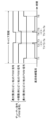
- FIG. 4 is a schematic diagram showing an example of a state in which the current sensor 500 cannot correctly detect the DC bus current when the conduction pattern switching period is shorter than the detection time of the current sensor 500.
- the horizontal axis represents time.
- the vertical axis represents the voltage of each PWM signal, and the current of the DC bus current.
- the period (T3-T2 or T5-T4) during which the voltage of one of the two PWM signals that make up the duty command changes until the other PWM signal changes is shorter than the detection time Ta of the current sensor 500 corresponds to the period near the timing when the voltages of any two phases of the three-phase AC voltage cross.
- the period during which the voltage of one of the two PWM signals that make up the duty command changes until the other PWM signal changes corresponds to the period surrounded by circles in the waveform of the three-phase AC voltage output by the inverter circuit 10 shown in FIG.
- the predetermined phase the period of the phase (hereinafter also referred to as the "predetermined phase") during which the voltage difference between any two phases of the three-phase AC voltage is equal to or less than a predetermined value.
- the current calculation unit 20 calculates the d-axis current di flowing through the d-axis of the motor 200 and the q-axis current qi flowing through the q-axis of the motor 200 based on the DC bus current detected by the current sensor 500.
- the current calculation unit 20 includes a three-phase current calculation unit 21 and a d/q axis conversion unit 22.
- the three-phase current calculation unit 21 calculates the U-phase current Ui, the V-phase current Vi, and the W-phase current Wi based on the DC bus current detected by the current sensor 500.
- the DC bus current detected by the current sensor 500 does not necessarily have a correct value. Therefore, only during this first period, the U-phase current Ui, V-phase current Vi, and W-phase current Wi calculated by the three-phase current calculation unit 21 do not necessarily have correct values.
- the d/q axis conversion unit 22 converts the U-phase current Ui, V-phase current Vi, and W-phase current Wi calculated by the three-phase current calculation unit 21 into a d-axis current di and a q-axis current qi.
- the d-axis current di and the q-axis current qi converted by the d/q-axis converter 22 do not necessarily have correct values, similar to the U-phase current Ui, the V-phase current Vi, and the W-phase current Wi.
- the rotation speed estimation unit 30 calculates the estimated rotation speed ⁇ of the motor 200 based on the d-axis current di and the q-axis current qi calculated by the current calculation unit 20, and the d-axis applied voltage command dv_req (described later) to be applied to the d-axis of the motor 200 and the q-axis applied voltage command qv_req (described later) to be applied to the q-axis of the motor 200 calculated by the voltage command calculation unit 50 (described later).
- the rotation speed estimation unit 30 includes an induced voltage calculation unit 31, a first switching unit 32, and a first proportional integral calculation unit 33.
- the induced voltage calculation unit 31 calculates an induced voltage residual angle ⁇ error, which indicates the angle with respect to the q axis of a vector whose d-axis component is a d-axis estimated induced voltage residual ed, which indicates the residual of the induced voltage induced on the d-axis of the motor 200, and whose q-axis component is a q-axis estimated induced voltage residual eq, which indicates the residual of the induced voltage induced on the q-axis of the motor 200, based on the d-axis current di and q-axis current qi calculated by the current calculation unit 20, the d-axis applied voltage command dv_req (described later) and the q-axis applied voltage command qv_req (described later) calculated by the voltage command calculation unit 50 (described later), and the estimated rotation speed ⁇ calculated by the rotation speed estimation unit 30.
- the induced voltage residual angle ⁇ error calculated by the induced voltage calculation unit 31 is not necessarily a correct value, similar to the d-axis current di and the q-axis current qi.
- the first switching unit 32 switches between zero and the induced voltage residual angle ⁇ error calculated by the induced voltage calculation unit 31 during a first period and a second period other than the first period, and outputs the switched value.
- zero refers to a dummy value that does not substantially affect the control of the motor 200.
- motor 200 is a brushless motor that rotates at a constant speed for a long period of time and accelerates and decelerates only slowly. Therefore, the value of the induced voltage residual angle ⁇ error in motor 200 always remains near zero.
- the first proportional integral calculation unit 33 performs proportional integral calculation using the signal output from the first switching unit 32 as an input signal, and calculates the estimated rotational speed ⁇ of the motor 200 and the estimated rotational position ⁇ of the motor 200.
- FIG. 5 is a block diagram showing the configuration of the rotation speed estimation unit 30 according to the embodiment.
- the induced voltage calculation unit 31 has a d-axis induced voltage residual calculation unit 301, a q-axis induced voltage residual calculation unit 302, and an induced voltage residual angle calculation unit 303.
- the d-axis induced voltage residual calculation unit 301 calculates the d-axis estimated induced voltage residual ed based on the d-axis current di and the q-axis current qi calculated by the current calculation unit 20, the d-axis applied voltage command dv_req (described later) calculated by the voltage command calculation unit 50 (described later), and the estimated rotation speed ⁇ calculated by the rotation speed estimation unit 30.
- the q-axis induced voltage residual calculation unit 302 calculates the q-axis estimated induced voltage residual eq based on the d-axis current di and the q-axis current qi calculated by the current calculation unit 20, the q-axis applied voltage command qv_req (described later) calculated by the voltage command calculation unit 50 (described later), and the estimated rotation speed ⁇ calculated by the rotation speed estimation unit 30.
- the induced voltage residual angle calculation unit 303 calculates the induced voltage residual angle ⁇ error based on the d-axis estimated induced voltage residual ed calculated by the d-axis induced voltage residual calculation unit 301 and the q-axis estimated induced voltage residual eq calculated by the q-axis induced voltage residual calculation unit 302.
- the d-axis induced voltage residual calculation unit 301 has a second switching unit 312 and a second proportional integral calculation unit 322.
- the second switching unit 312 switches between outputting zero and a d-axis estimated current residual indicating the residual of the d-axis current di during a first period and during a second period other than the first period.
- zero refers to a dummy value that does not substantially affect the control of the motor 200.
- motor 200 is a brushless motor that rotates at a constant speed for a long period of time and accelerates and decelerates only slowly. For this reason, the d-axis estimated current residual in motor 200 always remains near zero.
- the second proportional integral calculation unit 322 performs proportional integral calculation using the signal output from the second switching unit 312 as an input signal, and calculates the d-axis estimated induced voltage residual ed.
- the q-axis induced voltage residual calculation unit 302 has a third switching unit 313 and a third proportional integral calculation unit 323.
- the third switching unit 313 switches between outputting zero and a q-axis estimated current residual indicating the residual of the q-axis current qi during a first period and during a second period other than the first period.
- zero refers to a dummy value that does not substantially affect the control of the motor 200.
- motor 200 is a brushless motor that rotates at a constant speed for a long period of time and accelerates and decelerates only slowly. For this reason, the q-axis estimated current residual in motor 200 always remains near zero.
- the third proportional integral calculation unit 323 performs proportional integral calculation using the signal output from the third switching unit 313 as an input signal, and calculates the q-axis estimated induced voltage residual eq.
- the target rotation speed calculation unit 40 acquires an operation command for the motor 200 output from an external device, and calculates a target rotation speed ⁇ * for the motor 200 based on the acquired operation command.
- the operation command is a PWM signal with a fixed period of 500 Hz, the duty ratio of which indicates the target rotation speed.
- the target rotation speed calculation unit 40 includes a PWM signal detection unit 41, a duty ratio detection unit 42, and a target rotation speed conversion unit 43.
- the PWM signal detection unit 41 detects the PWM signal, which is an operation command for the motor 200, output from an external device, and acquires the detected PWM signal.
- the duty ratio detection unit 42 detects the duty ratio of the PWM signal acquired by the PWM signal detection unit 41.
- the target rotation speed conversion unit 43 calculates the target rotation speed ⁇ * indicated by the operation command based on the duty ratio detected by the duty ratio detection unit 42.
- the target rotation speed conversion unit 43 may, for example, store a table indicating the correspondence between the duty ratio and the target rotation speed, and calculate the target rotation speed ⁇ * indicated by the operation command based on the duty ratio detected by the duty ratio detection unit 42 and the stored table.
- the voltage command calculation unit 50 calculates a duty command based on the difference between the target rotation speed ⁇ * calculated by the target rotation speed calculation unit 40 and the estimated rotation speed ⁇ calculated by the rotation speed estimation unit 30 .
- the voltage command calculation unit 50 includes a speed PI control unit 51, a current PI control unit 52, an inverse d/q axis conversion unit 53, and a duty ratio calculation unit 54.
- the speed PI control unit 51 calculates a d-axis command current di_req and a q-axis command current qi_req for proportional-integral control of the rotational speed of the motor 200 so as to bring this difference closer to zero.
- the speed PI control unit 51 normally calculates the q-axis command current qi_req as a fixed value.
- the current PI control unit 52 calculates the d-axis applied voltage command dv_req and the q-axis applied voltage command qv_req for proportional-integral control of the current flowing through the motor 200 based on the d-axis command current di_req and the q-axis command current qi_req calculated by the speed PI control unit 51 and the d-axis current di and q-axis current qi converted by the d/q-axis conversion unit 22, so that the difference between the d-axis command current di_req and the d-axis current di approaches zero, and the difference between the q-axis command current qi_req and the q-axis current qi approaches zero.
- the inverse d/q axis converter 53 converts the d axis applied voltage command dv_req and the q axis applied voltage command qv_req into a U phase applied voltage command Uv_req, a V phase applied voltage command Vv_req, and a W phase applied voltage command Wv_req based on the d axis applied voltage command dv_req and the q axis applied voltage command qv_req calculated by the current PI controller 52 and the estimated rotational position ⁇ calculated by the rotational speed estimator 30.
- the duty ratio calculation unit 54 converts the U-phase applied voltage command Uv_req, the V-phase applied voltage command Vv_req, and the W-phase applied voltage command Wv_req, which have been converted by the inverse d/q axis conversion unit 53, into duty ratios, calculates a duty command in PWM format, and outputs the calculated duty command in PWM signal format to the inverter circuit 10.
- the motor control device 100 configured as described above calculates the estimated rotation speed ⁇ of the motor 200 by switching between zero and the induced voltage residual angle ⁇ error in the first period in which the DC bus current detected by the current sensor 500 is not necessarily a correct value, i.e., the first period in which the value of the calculated induced voltage residual angle ⁇ error is not necessarily a correct value, and the second period other than the first period.
- motor 200 is a brushless motor that rotates at a constant speed for a long period of time and only accelerates and decelerates slowly. Therefore, the value of the induced voltage residual angle ⁇ error in motor 200 always remains close to zero.
- the motor control device 100 configured as described above is a motor control device that employs a one-shunt current detection method and is capable of controlling the motor even when the first period exists.
- the motor control device 100 configured as described above does not calculate the current values of each phase of the three-phase AC during the first period based on the DC bus current detected immediately before the first period.
- the amount of calculation required to calculate the current values of each phase of the three-phase AC during the first period does not increase compared to the amount of calculation required during other periods.
- the motor control device 100 configured as described above can be realized by using an inexpensive microcomputer with low processing power, without using the expensive microcomputer with high processing power required for the motor control device described in Patent Document 1.
- the amount of calculations in calculating the current values of each phase of the three-phase AC in the first period does not increase compared to the amount of calculations in other periods. Therefore, power consumption in controlling the motor 200 is reduced compared to the motor control device described in Patent Document 1.
- the motor control device 100 configured as described above does not intentionally distort the voltage waveform of each phase of the three-phase AC voltage supplied to the motor 200 from an ideal sine wave.
- the motor control device 100 of this embodiment includes an inverter circuit 10 that outputs a three-phase AC voltage to the motor 200 by switching the power supply voltage of the DC power supply 300, a current calculation unit 20 that calculates a d-axis current flowing in the d-axis of the motor 200 and a q-axis current flowing in the q-axis of the motor based on the current flowing between the DC power supply 300 and the inverter circuit 10, a rotational speed estimation unit 30 that calculates an estimated rotational speed of the motor 200 based on the d-axis current and the q-axis current, a target rotational speed calculation unit 40 that calculates a target rotational speed of the motor 200 based on an operation command for the motor 200, and a voltage command calculation unit 50 that calculates a duty command to control the switching performed by the inverter circuit 10 based on the difference between the target rotational speed and the estimated rotational speed.
- a current calculation unit 20 that calculates a d-axis current flowing in the d-axis
- the rotation speed estimation unit 30 has an induced voltage calculation unit 31 that calculates an induced voltage residual angle indicating the angle with respect to the q axis of a vector having a d-axis estimated induced voltage residual indicating the residual of the induced voltage induced on the d-axis of the motor 200 as a d-axis component and a q-axis estimated induced voltage residual indicating the residual of the induced voltage induced on the q-axis of the motor 200 as a q-axis component based on the d-axis current and the q-axis current; a first switching unit 32 that switches between zero and the induced voltage residual angle and outputs them during a first period in which the three-phase AC voltage is within a predetermined phase range and during a second period other than the first period; and a first proportional integral calculation unit 33 that performs proportional integral calculation using the signal output from the first switching unit 32 as an input signal to calculate an estimated rotation speed.
- the motor control device 100 is a motor control device that employs a single-shunt current detection method and can control the motor even when a specific phase period exists.
- the induced voltage calculation unit 31 has a d-axis induced voltage residual calculation unit 301 that calculates a d-axis estimated induced voltage residual based on the d-axis current and the q-axis current, a q-axis induced voltage residual calculation unit 302 that calculates a q-axis estimated induced voltage residual based on the d-axis current and the q-axis current, and an induced voltage residual angle calculation unit 303 that calculates an induced voltage residual angle based on the d-axis estimated induced voltage residual and the q-axis estimated induced voltage residual.
- the d-axis induced voltage residual calculation unit 301 has a second switching function that switches between zero and a d-axis estimated current residual indicating the residual of the d-axis current and outputs the d-axis estimated current residual in the first period and the second period, respectively.
- the q-axis induced voltage residual calculation unit 302 has a third switching unit 313 that switches between zero and a q-axis estimated current residual indicating the residual of the q-axis current in the first period and the second period, and a third proportional integral calculation unit 323 that performs a proportional integral calculation using the signal output from the third switching unit 313 as an input signal and calculates the q-axis estimated induced voltage residual.
- the specified phase is a phase in which the voltage difference between any two phases of the three-phase AC voltage is equal to or less than a specified value.
- This disclosure can be widely used in motor control devices that control motors.
- MOTOR CONTROL SYSTEM 10 INVERTER CIRCUIT 20 CURRENT CALCULATION UNIT 21 THREE-PHASE CURRENT CALCULATION UNIT 22 D/Q AXIS CONVERSION UNIT 30 ROTATIONAL SPEED ESTIMATION UNIT 31 INDUCED VOLTAGE CALCULATION UNIT 32 FIRST SWITCHING UNIT 33 FIRST PROPORTIONAL AND INTEGRAL OPERATION UNIT 40 TARGET ROTATAL SPEED CALCULATION UNIT 41 PWM SIGNAL DETECTION UNIT 42 DUTY RATIO DETECTION UNIT 43 TARGET ROTATAL SPEED CONVERSION UNIT 50 VOLTAGE COMMAND CALCULATION UNIT 51 SPEED PI CONTROL UNIT 52 CURRENT PI CONTROL UNIT 53 INVERSE D/Q AXIS CONVERSION UNIT 54 DUTY RATIO CALCULATION UNIT 100 MOTOR CONTROL DEVICE 200 MOTOR 210 BLOWER F
Landscapes
- Engineering & Computer Science (AREA)
- Power Engineering (AREA)
- Control Of Ac Motors In General (AREA)
Priority Applications (3)
| Application Number | Priority Date | Filing Date | Title |
|---|---|---|---|
| CN202480027045.XA CN121219954A (zh) | 2023-04-27 | 2024-04-11 | 马达控制装置 |
| JP2025516718A JPWO2024225067A1 (https=) | 2023-04-27 | 2024-04-11 | |
| EP24796823.3A EP4704332A1 (en) | 2023-04-27 | 2024-04-11 | Motor control device |
Applications Claiming Priority (2)
| Application Number | Priority Date | Filing Date | Title |
|---|---|---|---|
| JP2023-073162 | 2023-04-27 | ||
| JP2023073162 | 2023-04-27 |
Publications (1)
| Publication Number | Publication Date |
|---|---|
| WO2024225067A1 true WO2024225067A1 (ja) | 2024-10-31 |
Family
ID=93256500
Family Applications (1)
| Application Number | Title | Priority Date | Filing Date |
|---|---|---|---|
| PCT/JP2024/014736 Ceased WO2024225067A1 (ja) | 2023-04-27 | 2024-04-11 | モータ制御装置 |
Country Status (4)
| Country | Link |
|---|---|
| EP (1) | EP4704332A1 (https=) |
| JP (1) | JPWO2024225067A1 (https=) |
| CN (1) | CN121219954A (https=) |
| WO (1) | WO2024225067A1 (https=) |
Citations (4)
| Publication number | Priority date | Publication date | Assignee | Title |
|---|---|---|---|---|
| WO2005006534A1 (ja) * | 2003-07-15 | 2005-01-20 | Matsushita Electric Industrial Co., Ltd. | 空気調和機の圧縮機用電動機駆動装置 |
| JP2016201872A (ja) * | 2015-04-07 | 2016-12-01 | 日立オートモティブシステムズ株式会社 | モータ駆動装置及び3相ブラシレスモータの相電流検出方法 |
| JP2018086139A (ja) | 2016-11-29 | 2018-06-07 | サミー株式会社 | 弾球遊技機 |
| JP2019055748A (ja) | 2017-09-22 | 2019-04-11 | 本田技研工業株式会社 | 車両制御装置、車両制御方法、及びプログラム |
-
2024
- 2024-04-11 WO PCT/JP2024/014736 patent/WO2024225067A1/ja not_active Ceased
- 2024-04-11 JP JP2025516718A patent/JPWO2024225067A1/ja active Pending
- 2024-04-11 EP EP24796823.3A patent/EP4704332A1/en active Pending
- 2024-04-11 CN CN202480027045.XA patent/CN121219954A/zh active Pending
Patent Citations (4)
| Publication number | Priority date | Publication date | Assignee | Title |
|---|---|---|---|---|
| WO2005006534A1 (ja) * | 2003-07-15 | 2005-01-20 | Matsushita Electric Industrial Co., Ltd. | 空気調和機の圧縮機用電動機駆動装置 |
| JP2016201872A (ja) * | 2015-04-07 | 2016-12-01 | 日立オートモティブシステムズ株式会社 | モータ駆動装置及び3相ブラシレスモータの相電流検出方法 |
| JP2018086139A (ja) | 2016-11-29 | 2018-06-07 | サミー株式会社 | 弾球遊技機 |
| JP2019055748A (ja) | 2017-09-22 | 2019-04-11 | 本田技研工業株式会社 | 車両制御装置、車両制御方法、及びプログラム |
Non-Patent Citations (1)
| Title |
|---|
| See also references of EP4704332A1 |
Also Published As
| Publication number | Publication date |
|---|---|
| CN121219954A (zh) | 2025-12-26 |
| JPWO2024225067A1 (https=) | 2024-10-31 |
| EP4704332A1 (en) | 2026-03-04 |
Similar Documents
| Publication | Publication Date | Title |
|---|---|---|
| JP5958477B2 (ja) | インバータ装置 | |
| JP4749874B2 (ja) | 電力変換装置及びそれを用いたモータ駆動装置 | |
| US20070296371A1 (en) | Position sensorless control apparatus for synchronous motor | |
| KR101947934B1 (ko) | 전력 변환 장치 및 이것을 사용한 전동 파워 스티어링 장치 | |
| JP6217554B2 (ja) | インバータ装置 | |
| JP6389425B2 (ja) | モータ駆動制御装置および回転状態検出方法 | |
| JP2015208143A (ja) | 電動機駆動装置 | |
| JP2013017363A (ja) | モータ制御装置 | |
| WO2015133317A1 (ja) | インバータ制御装置及びインバータ装置 | |
| JP5790390B2 (ja) | 交流モータの制御装置および制御方法 | |
| WO2021200389A1 (ja) | モータ制御装置、モータシステム及びモータ制御方法 | |
| JP6483043B2 (ja) | モータ制御装置及びモータ駆動回路の制御方法 | |
| JP6935349B2 (ja) | モータ駆動装置 | |
| WO2017056258A1 (ja) | 電力制御方法、及び、電力制御装置 | |
| WO2024225067A1 (ja) | モータ制御装置 | |
| JP2014171293A (ja) | 冷却ファンの制御装置、及び制御方法 | |
| JP2009247089A (ja) | ブラシレスモータ用インバータの制御方法及びそれを用いた装置 | |
| JP2000350487A (ja) | ブラシレスモータの制御装置 | |
| JP2016154422A (ja) | モータ駆動制御装置及びモータ駆動制御装置の制御方法 | |
| Lai et al. | Back-EMF detection technique of brushless DC motor drives for wide range control | |
| WO2020121368A1 (ja) | モータ駆動装置及びモータ駆動方法 | |
| US11196378B2 (en) | Motor control device | |
| KR101854530B1 (ko) | 차재용 전동 압축기 | |
| JP6471670B2 (ja) | 電力制御方法、及び、電力制御装置 | |
| JP2025155170A (ja) | モータドライバ及び半導体装置 |
Legal Events
| Date | Code | Title | Description |
|---|---|---|---|
| 121 | Ep: the epo has been informed by wipo that ep was designated in this application |
Ref document number: 24796823 Country of ref document: EP Kind code of ref document: A1 |
|
| WWE | Wipo information: entry into national phase |
Ref document number: 2025516718 Country of ref document: JP |
|
| WWE | Wipo information: entry into national phase |
Ref document number: CN202480027045X Country of ref document: CN |
|
| WWE | Wipo information: entry into national phase |
Ref document number: 2024796823 Country of ref document: EP |
|
| NENP | Non-entry into the national phase |
Ref country code: DE |
|
| ENP | Entry into the national phase |
Ref document number: 2024796823 Country of ref document: EP Effective date: 20251127 |
|
| ENP | Entry into the national phase |
Ref document number: 2024796823 Country of ref document: EP Effective date: 20251127 |
|
| ENP | Entry into the national phase |
Ref document number: 2024796823 Country of ref document: EP Effective date: 20251127 |
|
| ENP | Entry into the national phase |
Ref document number: 2024796823 Country of ref document: EP Effective date: 20251127 |
|
| ENP | Entry into the national phase |
Ref document number: 2024796823 Country of ref document: EP Effective date: 20251127 |
|
| ENP | Entry into the national phase |
Ref document number: 2024796823 Country of ref document: EP Effective date: 20251127 |
|
| ENP | Entry into the national phase |
Ref document number: 2024796823 Country of ref document: EP Effective date: 20251127 |
|
| ENP | Entry into the national phase |
Ref document number: 2024796823 Country of ref document: EP Effective date: 20251127 |
|
| ENP | Entry into the national phase |
Ref document number: 2024796823 Country of ref document: EP Effective date: 20251127 |
|
| WWP | Wipo information: published in national office |
Ref document number: 2024796823 Country of ref document: EP |