WO2024214489A1 - ワイヤとウェビングを接続するための接続部材 - Google Patents
ワイヤとウェビングを接続するための接続部材 Download PDFInfo
- Publication number
- WO2024214489A1 WO2024214489A1 PCT/JP2024/010430 JP2024010430W WO2024214489A1 WO 2024214489 A1 WO2024214489 A1 WO 2024214489A1 JP 2024010430 W JP2024010430 W JP 2024010430W WO 2024214489 A1 WO2024214489 A1 WO 2024214489A1
- Authority
- WO
- WIPO (PCT)
- Prior art keywords
- wire
- webbing
- connection member
- loop
- rivet
- Prior art date
- Legal status (The legal status is an assumption and is not a legal conclusion. Google has not performed a legal analysis and makes no representation as to the accuracy of the status listed.)
- Ceased
Links
Images






Classifications
-
- B—PERFORMING OPERATIONS; TRANSPORTING
- B60—VEHICLES IN GENERAL
- B60R—VEHICLES, VEHICLE FITTINGS, OR VEHICLE PARTS, NOT OTHERWISE PROVIDED FOR
- B60R22/00—Safety belts or body harnesses in vehicles
- B60R22/18—Anchoring devices
- B60R22/195—Anchoring devices with means to tension the belt in an emergency, e.g. means of the through-anchor or splitted reel type
- B60R22/1952—Transmission of tensioning power by cable; Return motion locking means therefor
-
- B—PERFORMING OPERATIONS; TRANSPORTING
- B60—VEHICLES IN GENERAL
- B60R—VEHICLES, VEHICLE FITTINGS, OR VEHICLE PARTS, NOT OTHERWISE PROVIDED FOR
- B60R22/00—Safety belts or body harnesses in vehicles
- B60R22/18—Anchoring devices
- B60R22/195—Anchoring devices with means to tension the belt in an emergency, e.g. means of the through-anchor or splitted reel type
-
- B—PERFORMING OPERATIONS; TRANSPORTING
- B60—VEHICLES IN GENERAL
- B60R—VEHICLES, VEHICLE FITTINGS, OR VEHICLE PARTS, NOT OTHERWISE PROVIDED FOR
- B60R22/00—Safety belts or body harnesses in vehicles
- B60R22/18—Anchoring devices
- B60R22/195—Anchoring devices with means to tension the belt in an emergency, e.g. means of the through-anchor or splitted reel type
- B60R22/1954—Anchoring devices with means to tension the belt in an emergency, e.g. means of the through-anchor or splitted reel type characterised by fluid actuators, e.g. pyrotechnic gas generators
-
- B—PERFORMING OPERATIONS; TRANSPORTING
- B60—VEHICLES IN GENERAL
- B60R—VEHICLES, VEHICLE FITTINGS, OR VEHICLE PARTS, NOT OTHERWISE PROVIDED FOR
- B60R22/00—Safety belts or body harnesses in vehicles
- B60R22/18—Anchoring devices
- B60R22/195—Anchoring devices with means to tension the belt in an emergency, e.g. means of the through-anchor or splitted reel type
- B60R22/1954—Anchoring devices with means to tension the belt in an emergency, e.g. means of the through-anchor or splitted reel type characterised by fluid actuators, e.g. pyrotechnic gas generators
- B60R22/1955—Linear actuators
-
- B—PERFORMING OPERATIONS; TRANSPORTING
- B60—VEHICLES IN GENERAL
- B60R—VEHICLES, VEHICLE FITTINGS, OR VEHICLE PARTS, NOT OTHERWISE PROVIDED FOR
- B60R22/00—Safety belts or body harnesses in vehicles
- B60R22/18—Anchoring devices
- B60R22/26—Anchoring devices secured to the seat
-
- B—PERFORMING OPERATIONS; TRANSPORTING
- B60—VEHICLES IN GENERAL
- B60R—VEHICLES, VEHICLE FITTINGS, OR VEHICLE PARTS, NOT OTHERWISE PROVIDED FOR
- B60R22/00—Safety belts or body harnesses in vehicles
- B60R22/34—Belt retractors, e.g. reels
- B60R22/46—Reels with means to tension the belt in an emergency by forced winding up
- B60R2022/468—Reels with means to tension the belt in an emergency by forced winding up characterised by clutching means between actuator and belt reel
Definitions
- the present invention relates to a connecting member for connecting a wire and a webbing.
- Pretensioners often have a quick fix as a connecting member in the case of models that retract a lap anchor, and a buckle in the case of models that retract a locking tongue, to connect the wire and webbing.
- Models that retract a lap anchor via a quick fix are generally known as pyroelectric lap pretensioners (PLP), and models that retract a locking tongue via a buckle are generally known as pyroelectric buckle pretensioners (PBP).
- PLP pyroelectric lap pretensioners
- PBP pyroelectric buckle pretensioners
- the gap between the floor and the seat has become narrower than before.
- the mounting position of the drive unit of the pretensioner has also moved closer to the seat.
- the connection member that connects the wire and the webbing is always located at a position that protrudes slightly from the seat on the side of the seat. If the connection member protrudes from the seat, the occupant may push the connection member down against the seat with their buttocks when getting in and out of the car.
- the connection member is pushed down against the seat, the wire, which is a flexible member, is bent and subjected to excessive tensile load. If this bending action is repeated, there is a risk that fatigue breakage will occur in the wire.
- the present invention was made to solve these problems, and provides a connecting member for use in a pretensioner that connects a wire and a webbing and does not cause fatigue breakage in the wire even if the occupant pushes down when getting on or off the vehicle.
- the connecting member in the first aspect of the present invention is a connecting member for connecting a wire connected to a drive unit of a pretensioner and a webbing for restraining an occupant in a seat, and includes a fixing portion for fixing the webbing so that it extends in one direction from the connecting member, and a shaft portion for winding the wire so that it extends in the opposite direction from the connecting member, and the fixing portion and the shaft portion are arranged so that a first plane including the wide surface of the webbing extending in one direction and a second plane including the loop surface of the loop that the wire forms around the axis of the shaft portion intersect with each other.
- the present invention provides a connection member for use in a pretensioner that connects a wire and a webbing and does not cause fatigue breakage in the wire even if the wire is pushed down when an occupant gets in or out of the vehicle.
- FIG. 1 is a perspective view of a quick fix according to an embodiment of the present invention and related peripheral elements.
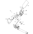
- FIG. 2 is an exploded perspective view showing the configuration of the Quick Fix.
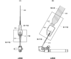
- FIG. 2 is a view taken along a specific arrow direction shown in FIG. 1 .
- FIG. 2 is an enlarged view showing the configuration of a channel.
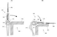
- FIG. FIG. 13 shows the change in wire as the Quick Fix is tilted.
- FIG. 13 is a perspective view of a crimping ring according to a first modified example.
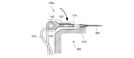
- FIG. 13 is a diagram showing the state of the quick fix of the first modified example after it has been tilted.
- FIG. 2 is a perspective view showing the buckle according to the embodiment and related peripheral elements.
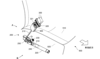
- FIG. 1 is a perspective view showing a quick fix 100 according to this embodiment and related peripheral elements.
- the quick fix 100 is one form of connecting member for connecting a wire 210 connected to a drive unit of a pretensioner 200 and a webbing 300 for restraining an occupant to a seat 900.
- the webbing 300 is often referred to as a seat belt.
- the pretensioner 200 is a device that is activated in an emergency such as a vehicle collision and retracts the webbing 300 via the wire 210, thereby holding the occupant against the seat and more firmly restraining him/her.
- the quick fix 100 of this embodiment is used in a pyrotechnic lap pretensioner (PLP), which is a model of pretensioner 200 that mainly retracts a lap anchor.
- PLP pyrotechnic lap pretensioner
- the vehicles assumed are various private vehicles and transport vehicles, such as BEVs (Electric Vehicles) and HEVs (Hybrid Electric Vehicles) in which the battery is located under the seat where the occupant sits, and gasoline-powered vehicles with low seating positions such as sports cars.
- the pretensioner 200 is disposed on a side surface 920 of a seat 900 arranged in a vehicle. Note that in FIG. 1, the direction indicated by the outlined arrow is the front of the vehicle, and an occupant enters the vehicle through a door (not shown) provided on the side of the vehicle and sits on the seat surface 910.
- the pretensioner 200 mainly comprises a wire 210, a cylinder 220, a gas generator 230, a piston 240, and a fixing bolt 250.
- the wire 210 is, for example, a wire rope made of twisted metal wires, and is a tension transmission member also known as a cable. At least one end of the wire 210 is connected to the piston 240.
- the cylinder 220 is a cylindrical member that movably houses the piston 240.
- the gas generator 230 is a power source constituted by, for example, a micro gas generator (MGG).
- MMGG micro gas generator
- the cylinder 220, the gas generator 230, and the piston 240 function as the driving unit of the pretensioner 200.
- the gas generator 230 is electrically connected to an ECU installed in the vehicle, and generates gas when it receives an operation signal from the ECU.
- the generated gas flows into the cylindrical space in the cylinder 220, instantly increasing the internal pressure and causing the piston 240 to move rapidly.
- the piston 240 moves, a portion of the wire 210 connected to the piston 240 is drawn into the cylindrical space, and as a result, the webbing 300 connected via the quick fix 100 is also drawn below the seat 900, increasing the restraining force that restrains the occupant to the seat 900.
- the drive section of the pretensioner 200 which includes the cylinder 220, the gas generator 230, and the piston 240, is fixed to the frame of the vehicle or the seat 900 via a fixing bolt 250.
- the wire 210 is routed around the axis of the fixing bolt 250 and connected to the piston 240.
- the end of the webbing 300 is connected to a lap anchor 310, which is formed, for example, from a metal plate, and the lap anchor 310 is fixed to the quick fix 100.
- a lap anchor 310 is fixed to the quick fix 100 by an assembly worker, a vehicle occupant cannot easily attach or detach the lap anchor 310 to or from the quick fix 100 unless using tools or the like.
- FIG. 2 is an exploded perspective view showing the configuration of the quick fix 100.
- the quick fix 100 is mainly composed of a cover 110, a channel 120, a wire rivet 130, a guide ring 141, a latch pin 150, a latch piece 151, and a biasing spring 152.
- the cover 110 forms the housing of the quick fix 100 and includes a first cover 111 and a second cover 112 that are combined opposite each other.
- the channel 120 is a base material that connects the wire 210 and the webbing 300 to each other, and is formed, for example, by bending a metal plate.
- the channel 120 may be configured by combining multiple folded metal plates so as to form a slit 123 into which the wrap anchor 310 is inserted.
- the tip side of the wire rivet 130 is inserted into an insertion hole 121 provided in the channel 120 and tightened, and functions as an axis for winding the wire 210.
- the wire 210 is wound in a loop around the axis of the wire rivet 130.
- Two guide rings 141 are inserted into the axis of the wire rivet 130 so as to face each other and sandwich the wire 210 from both sides.
- the guide rings 141 are holding members that hold the wire 210 and rotate together with the wire rivet 130. The specific configuration will be described later.
- the latch pin 150, the latch piece 151, and the biasing spring 152 are attached to the channel 120 and function as a fixing portion for fixing the lap anchor 310.
- the tip of the lap anchor 310 is inserted into the slit 123 of the channel 120, and the locking groove 311 provided at the tip engages with the latch piece 151 biased by the biasing spring 152, thereby fixing the lap anchor 310 to the channel 120.
- the direction in which the wire 210 wound around the quick fix 100 extends from the quick fix 100 is opposite to the direction in which the webbing 300 fixed to the quick fix 100 extends from the quick fix 100.
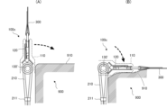
- FIG. 3 is an arrow view from a specific direction shown in FIG. 1.
- FIG. 3(A) is an A-view from direction A shown in FIG. 1
- FIG. 3(B) is a B-view from direction B shown in FIG. 1.
- the wire 210 wound around the quick fix 100 forms a loop surface (hatched portion).
- a plane including this loop surface is defined as the second plane.
- the second plane is a plane parallel to the width direction of the vehicle and is a plane that is approximately perpendicular to the side surface 920 of the seat 900.
- the loop surface may be assumed to be a surface that is in contact with the wire surface that forms the loop, or a surface formed by the central axis of the wire.
- the plane including the wide surface (hatched portion) of the webbing 300 fixed to the quick fix 100 is defined as the first plane.
- the first plane is a plane that is approximately parallel to the side surface 920 of the seat 900 and perpendicular to the width direction of the vehicle.
- the wide surface may be the front or back surface of the webbing 300.
- the quick fix 100 is provided with an axis around which the wire 210 is wound and a fixing part for fixing the lap anchor 310 so that the first and second planes defined in this way are perpendicular to each other.
- the axis and fixing part are realized using the wire rivet 130 and the latch piece 151, etc., which are disposed on the channel 120 as described above, but the axis and fixing part may be configured in various ways as long as the first and second planes are perpendicular to each other.
- the fixing part may be configured to directly clamp the end of the webbing 300 that does not have the lap anchor 310.
- the connecting member for connecting the wire 210 and the webbing 300 is not limited to the form of the quick fix.
- the connecting member may have an end provided with a slit-shaped insertion hole through which the webbing is inserted, and the webbing may be inserted into the insertion hole, folded back, and sewn together to be fixed to the connecting member.
- the insertion hole through which the webbing is inserted functions as the fixing part.
- Figure 4 is an enlarged view showing the configuration of the channel 120.
- Figure 4(A) is a view of the wire 210 wound around the wire rivet 130, as seen from the head side of the wire rivet 130 that is crimped into the channel 120
- Figure 4(B) is a cross-sectional view of C-C shown in Figure 4(A).
- the wire 210 forms a loop with the wire rivet 130 as the winding axis. Also, as shown in FIG. 4(B), even when the wire 210 rotates integrally with the wire rivet 130, two guide rings 141 are interposed to guide the wire 210 so that the loop does not spread away from the wire rivet 130.
- FIG. 5 is a perspective view of the guide ring 141.
- the guide ring 141 has a guide groove 141a for guiding the wire 210.
- the groove width of the guide groove 141a is set slightly wider than the diameter of the wire 210, so that the wire 210 can slide somewhat on the guide groove 141a.
- the trajectory of the guide groove 141a is formed in a U-shape so that the loop formed by the wire 210 does not spread around the axis of the wire rivet 130.
- the two guide rings 141 When the wire rivet 130 is tightened, the two guide rings 141 are inserted into the shaft of the wire rivet 130 with the guide grooves 141a facing each other and sandwiching the loop of the wire 210. When the wire rivet 130 is tightened against the channel 120, the two guide rings 141 are fixed to the shaft of the wire rivet 130. In this case, the two guide rings 141 do not rotate relative to the wire rivet 130, but rotate together with the rotation of the wire rivet 130. With this configuration, the shaft of the wire rivet 130 indirectly supports the wire 210 via the guide rings 141.
- the gap between the floor and the seat has become narrower than before.
- the mounting position of the pretensioner's drive unit has also moved closer to the seat.
- the seating position is originally low, so the mounting position of the pretensioner's drive unit was close to the seating surface. If the mounting position of the drive unit is close to the seating surface, the quick fix or buckle that connects the wire and webbing will always be located at a position that protrudes slightly from the seating surface on the side of the seat. If the quick fix or buckle protrudes from the seating surface, the occupant may push it down against the seating surface with their buttocks when getting in and out of the car.
- the wire which is a flexible member, is locally bent at the boundary and is subjected to excessive tensile load. If such bending action is repeated, there is a risk that fatigue breakage will occur in the wire.
- the quick fix 100 also protrudes from the seat surface 910. Therefore, it is assumed that the quick fix 100 will be pushed down by the passenger's buttocks, but the quick fix 100 in this embodiment prevents the wire 210 from being locally bent. This will be explained in detail using FIG. 6.
- Figure 6 shows the change in the wire 210 as the quick fix 100 is tilted.
- the cover 110 and the shaft of the wire rivet 130 are shown with dashed lines so that the state of the wire 210 can be seen.
- Figure 6 (A) shows the same state as that shown in Figure 1, where the quick-fix 100 is not tilted.
- the webbing 300 is either pulled up toward the shoulder anchor or draped across the occupant's waist, so that, as far as the periphery of the quick-fix 100 is concerned, the webbing 300 and wire 210 extend along an approximately straight line.
- the wire 210 forms a gentle loop without being bent beyond the curvature along the axis of the wire rivet 130.
- the quick fix 100 is also lifted up toward the shoulder anchor, and at least a part of it protrudes from the seat surface 910 of the seat 900. In this state, if the occupant attempts to sit on the seat 900 from outside the vehicle, the occupant may, for example, push the quick fix 100 down with their buttocks in the direction of the dotted arrow.
- FIG. 6B shows the state in which the quick fix 100 is pushed down and pressed against the seat surface 910.
- the guide ring 141 also tilts together with the channel 120, so that the downward U-shaped guide groove 141a is rotated 90 degrees, and the wire 210 is pulled out horizontally from the shaft of the wire rivet 130.
- the wire 210 since the wire 210 is connected to the drive unit of the pretensioner 200, it curves along a curve that smoothly connects the horizontal direction and the drive unit direction, as shown in the figure.
- the guide ring 141 allows the wire 210 to slide on the guide groove 141a, so that even if a large tensile force acts on the wire 210, it does not bend locally, but slides appropriately to release such tensile force and self-adjusts to draw a larger radius of curvature.
- the quick fix 100 has a first plane including the wide surface of the webbing 300 and a second plane including the loop surface of the wire 210 that are approximately perpendicular to each other, so that when the quick fix 100 is pushed down, the loop surface becomes approximately perpendicular to the seat surface 910, and the wire 210 is pulled out horizontally while sliding moderately, so that it is free from local bending. It is not bent at least beyond the curvature along the axis of the wire rivet 130. Therefore, even if the quick fix 100 is repeatedly tilted, the wire 210 will not break. Note that FIG.
- the guide ring 141 that allows the wire 210 to slide on the guide groove 141a is used, but instead of the guide ring 141, a crimping ring, which will be described later with reference to FIG. 12, may be used.
- the crimping ring presses and clamps the wire 210 so that it does not slide.
- Such a crimping ring is also a holding member that holds the wire 210 and rotates together with the wire rivet 130. If such a crimping ring is used, the wire 210 extends horizontally from the shaft of the wire rivet 130 without sliding within the crimping ring as the quick fix 100 is tilted, and smoothly curves toward the drive unit.
- the configuration of the crimping ring is not limited to the case where a sliding prevention protrusion that bites into the wire 210 is provided in the guide groove as described with reference to FIG. 12, and any configuration that clamps the wire 210 may be used.
- FIG. 7 is a perspective view of the crimping ring 144 according to the first modified example.
- the crimping ring 144 has a guide groove 144a that holds the wire 210 in place, like the guide ring 141, but its shape is not U-shaped, and the outer peripheral wall is semicircular and the inner peripheral wall is annular.
- a sliding prevention protrusion 144b is arranged in an area that is approximately surrounded by the outer peripheral wall.
- the wire 210 and the crimping ring 144 are fixed together.
- such a crimping ring 144 is also a holding member that holds the wire 210 and rotates together with the wire rivet 130.
- the wire 210 can be displaced around the axis of the wire rivet 130.
- FIG. 8 is a diagram showing the state of the quick fix 100a according to the first modified example after it has been tilted, and corresponds to FIG. 6(B).
- the quick fix 100a using the crimping ring 144 according to the first modified example is tilted and pressed against the seat 910
- the looped wire 210 receives a larger tensile force on the upper side of the wire rivet 130.
- the upper part of the wire 210 curves so as to wrap around the axis of the wire rivet 130 and heads toward the drive unit.
- the lower part of the wire 210 curves in accordance with the excess wire length (the part that protrudes from the shortest path) that is generated by the quick fix 100a being tilted, and heads toward the drive unit. Even with this type of quick fix 100a, it is possible to avoid the wire 210 becoming locally bent.
- Figure 9 is a diagram showing the change in wire 210 associated with tilting of quick fix 100b according to a second modified example of the above embodiment.
- Quick fix 100b according to the second modified example differs from the above-described quick fix 100 in that it employs wire rivet 130', which is a stepped rivet, instead of wire rivet 130, and in that it employs a rotating ring 142 instead of guide ring 141.
- wire rivet 130' which is a stepped rivet, instead of wire rivet 130
- rotating ring 142 instead of guide ring 141.
- FIG. 9(A) is a diagram corresponding to FIG. 6(A) and shows the state in which the quick fix 100b is not tilted.
- the wire rivet 130' is a stepped rivet as described above, and when tightened against the channel 120, a small gap is created between the wire rivet 130' and the rotating ring 142, which holds the wire 210 by clamping it, so that the rotating ring 142 can rotate around its axis.
- the rotating ring 142 is a rotating member that rotates around the axis of the wire rivet 130' while holding the loop of the wire 210, and is inserted into the shaft of the wire rivet 130' while holding the wire 210 by clamping it.
- the rotating ring 142 may be substantially the same member as the guide ring 141, and two of them are used as a set, facing each other and clamping the wire 210. However, since the wire 210 does not need to slide along the guide groove, two opposing rotating rings 142 may be configured to clamp the wire 210 and press it.
- Figure 9(B) is a diagram corresponding to Figure 6(B) and shows the state in which the quick fix 100b is pushed down and pressed against the seat surface 910.
- the rotating ring 142 can rotate around the axis of the wire rivet 130', so even if the wire rivet 130' fastened to the channel 120 rotates as the channel 120 tilts, the rotating ring 142 can substantially maintain its position while still clamping the wire 210.
- the loop of the wire 210 can substantially maintain its position and shape even if the quick fix 100b is pushed down. This makes it possible to avoid the wire 210 becoming locally bent.
- FIG. 10 is a diagram showing the change in wire 210 accompanying tilting of quick fix 100b according to the third modified example of the above embodiment.
- Quick fix 100c according to the third modified example adopts wire rivet 130' according to the second modified example, but differs from quick fix 100b according to the second modified example in that it omits pivot ring 142 and adopts wire band 211.
- the rest of the configuration is similar to quick fix 100b, the same elements are given the same reference numbers and their explanations are omitted.
- Figure 10(A) corresponds to Figure 9(A) and shows the quick fix 100c in an untilted state.
- the wire rivet 130' is a stepped rivet as described above, and forms a shaft portion having an axial length longer than the diameter of the wire 210 so that the loop of the wire 210 can rotate about its axis when riveted against the channel 120.
- the wire 210 is bound at the base of the loop by a wire band 211, which maintains the shape of the loop.
- Figure 10(B) is a diagram corresponding to Figure 9(B) and shows the state in which the quick fix 100c is pushed down and pressed against the seat surface 910.
- the loop of the wire 210 can rotate around the axis of the wire rivet 130', so that even if the wire rivet 130' fastened to the channel 120 rotates as the channel 120 tilts, the loop of the wire 210 can maintain its posture and shape.
- at least a portion of the loop of the wire 210 contacts the outer circumference of the wire rivet 130' and rotates around the axis relative to the wire rivet 130, so that the posture and shape of the loop are maintained. Therefore, even with such a simple configuration, it is possible to avoid the wire 210 becoming locally bent.
- FIG. 11 is a perspective view showing a buckle 400 according to another example of this embodiment and its related peripheral elements.
- Figure 11 corresponds to Figure 1, and configurations similar to those in the above-described embodiment are given the same reference numerals and descriptions thereof will be omitted unless otherwise noted.
- the connecting member for connecting the wire 210 connected to the drive unit of the pretensioner 200 and the webbing 300 for restraining the occupant in the seat is the buckle 400. While the fastening portion of the quick fix 100 fastens the webbing 300 so that it cannot be detached, the fastening portion of the buckle 400 has a fastening mechanism for fastening the webbing 300 so that it can be detached.
- the locking tongue 320 through which the webbing 300 is slidably inserted is provided with a tongue plate 321 that detachably connects it to the buckle 400, and the buckle 400 is provided with a locking mechanism that locks the tongue plate 321.
- the locking mechanism is a mechanism in which, for example, when the tongue plate 321 is inserted, it is locked by a biasing hook, and when a push button is pressed, the locked state is released.
- the locking tongue 320 has the function of dividing the webbing 300 into a portion that is hung diagonally across the occupant's chest and a portion that is hung horizontally across the occupant's waist, but when the locking tongue 320 is attached to the buckle 400, the direction in which the webbing 300 extends from the buckle 400 and the direction in which the wire 210 wound around the buckle 400 extends from the buckle 400 are roughly opposite.
- the buckle 400 also has a wire rivet 130, similar to the quick fix 100, and the wire 210 is wound around the axis of the wire rivet 130 in a loop. Therefore, in the buckle 400, the first plane including the wide surface of the webbing 300 and the second plane including the loop surface of the wire 210 are approximately perpendicular to each other. Then, when the buckle 400 is pushed down, the loop surface becomes approximately perpendicular to the seat surface 910, and the wire 210 is pulled out in the horizontal direction, so that local bending is avoided. Therefore, even if the buckle 400 is repeatedly tilted, the wire 210 will not break. This is also the case when the locking tongue 320 detaches from the buckle 400 and only the buckle 400 is tilted.
- the buckle 400 is often pushed down by the occupant with the locking tongue 320 detached.
- the locking tongue 320 is attached to the buckle 400 after the occupant sits on the seat 910. Therefore, it is preferable that the buckle 400 remains upright even when the locking tongue 320 is detached, so that the locking tongue 320 can be easily attached. Therefore, in the buckle 400, instead of the guide ring 141, a sliding prevention member that prevents the loop from sliding around the axis is used.
- Figure 12 is a perspective view of a crimping ring 143, which is an example of a sliding prevention member.
- the crimping ring 143 has a guide groove 143a that holds the wire 210, but the surface of the guide groove 143a has many anti-slide protrusions 143b arranged on it. Therefore, when two crimping rings 143 are placed opposite each other and the wire rivet 130 is crimped against the channel 120 so that the wire 210 is held between them, the anti-slide protrusions 143b bite into the wire 210, preventing the wire 210 from sliding.
- the above describes an example of the quick fix 100 and buckle 400 that are provided with a fixing part for fixing the webbing 300 and an axial part for winding the wire so that the first plane including the wide surface of the webbing 300 and the second plane including the loop surface of the wire 210 are approximately perpendicular to each other.
- the first plane and the second plane may intersect as long as the wire 210 is gently curved at least without being bent more than the curvature along the axial part of the wire rivet 130 when the quick fix 100 or the buckle 400 is pushed down. This relationship depends on the thickness of the wire 210 and the diameter of the axial part of the wire rivet 130, but it is sufficient that the first plane and the second plane intersect within a range of approximately 60 degrees to 120 degrees.
- the buckle 400 may adopt the winding configuration of the wire 210 in the quick fix 100b or the winding configuration of the wire 210 in the quick fix 100c.
Landscapes
- Engineering & Computer Science (AREA)
- Mechanical Engineering (AREA)
- Automotive Seat Belt Assembly (AREA)
Priority Applications (4)
| Application Number | Priority Date | Filing Date | Title |
|---|---|---|---|
| JP2025513849A JPWO2024214489A1 (cg-RX-API-DMAC7.html) | 2023-04-10 | 2024-03-18 | |
| KR1020257033632A KR20250162597A (ko) | 2023-04-10 | 2024-03-18 | 와이어와 웨빙을 접속하기 위한 접속 부재 |
| CN202480022869.8A CN120936518A (zh) | 2023-04-10 | 2024-03-18 | 用于连接金属丝与织带的连接部件 |
| EP24788519.7A EP4696563A1 (en) | 2023-04-10 | 2024-03-18 | Connection member for connecting wire and webbing |
Applications Claiming Priority (2)
| Application Number | Priority Date | Filing Date | Title |
|---|---|---|---|
| JP2023-063217 | 2023-04-10 | ||
| JP2023063217 | 2023-04-10 |
Publications (1)
| Publication Number | Publication Date |
|---|---|
| WO2024214489A1 true WO2024214489A1 (ja) | 2024-10-17 |
Family
ID=93059204
Family Applications (1)
| Application Number | Title | Priority Date | Filing Date |
|---|---|---|---|
| PCT/JP2024/010430 Ceased WO2024214489A1 (ja) | 2023-04-10 | 2024-03-18 | ワイヤとウェビングを接続するための接続部材 |
Country Status (5)
| Country | Link |
|---|---|
| EP (1) | EP4696563A1 (cg-RX-API-DMAC7.html) |
| JP (1) | JPWO2024214489A1 (cg-RX-API-DMAC7.html) |
| KR (1) | KR20250162597A (cg-RX-API-DMAC7.html) |
| CN (1) | CN120936518A (cg-RX-API-DMAC7.html) |
| WO (1) | WO2024214489A1 (cg-RX-API-DMAC7.html) |
Families Citing this family (1)
| Publication number | Priority date | Publication date | Assignee | Title |
|---|---|---|---|---|
| US12617368B2 (en) * | 2024-10-31 | 2026-05-05 | Toyota Motor Engineering & Manufacturing North America, Inc. | Seat belt buckle assemblies for use with a seat belt of a vehicle |
Citations (5)
| Publication number | Priority date | Publication date | Assignee | Title |
|---|---|---|---|---|
| JP2000177533A (ja) * | 1998-12-16 | 2000-06-27 | Nsk Ltd | バックル支持装置 |
| JP2002002444A (ja) * | 2000-06-26 | 2002-01-09 | Nsk Ltd | シートベルト装置 |
| US20060017275A1 (en) * | 2004-07-26 | 2006-01-26 | Autoliv Asp, Inc. | Cross-car adjustable strap buckle |
| JP2021116041A (ja) * | 2020-01-29 | 2021-08-10 | トヨタ自動車株式会社 | 車両用シートベルト装置 |
| JP2022071614A (ja) | 2020-10-28 | 2022-05-16 | Joyson Safety Systems Japan株式会社 | バックルプリテンショナ及びシートベルト装置 |
-
2024
- 2024-03-18 KR KR1020257033632A patent/KR20250162597A/ko active Pending
- 2024-03-18 WO PCT/JP2024/010430 patent/WO2024214489A1/ja not_active Ceased
- 2024-03-18 CN CN202480022869.8A patent/CN120936518A/zh active Pending
- 2024-03-18 JP JP2025513849A patent/JPWO2024214489A1/ja active Pending
- 2024-03-18 EP EP24788519.7A patent/EP4696563A1/en active Pending
Patent Citations (5)
| Publication number | Priority date | Publication date | Assignee | Title |
|---|---|---|---|---|
| JP2000177533A (ja) * | 1998-12-16 | 2000-06-27 | Nsk Ltd | バックル支持装置 |
| JP2002002444A (ja) * | 2000-06-26 | 2002-01-09 | Nsk Ltd | シートベルト装置 |
| US20060017275A1 (en) * | 2004-07-26 | 2006-01-26 | Autoliv Asp, Inc. | Cross-car adjustable strap buckle |
| JP2021116041A (ja) * | 2020-01-29 | 2021-08-10 | トヨタ自動車株式会社 | 車両用シートベルト装置 |
| JP2022071614A (ja) | 2020-10-28 | 2022-05-16 | Joyson Safety Systems Japan株式会社 | バックルプリテンショナ及びシートベルト装置 |
Non-Patent Citations (1)
| Title |
|---|
| See also references of EP4696563A1 |
Also Published As
| Publication number | Publication date |
|---|---|
| EP4696563A1 (en) | 2026-02-18 |
| JPWO2024214489A1 (cg-RX-API-DMAC7.html) | 2024-10-17 |
| CN120936518A (zh) | 2025-11-11 |
| KR20250162597A (ko) | 2025-11-18 |
Similar Documents
| Publication | Publication Date | Title |
|---|---|---|
| US9980537B2 (en) | Locking tongue | |
| JP5943512B2 (ja) | タングおよびこれを用いたシートベルト装置 | |
| US5899399A (en) | Seat belt pretensioner | |
| JP2006182103A (ja) | タングおよびこれを用いたシートベルト装置 | |
| JP2010155579A5 (cg-RX-API-DMAC7.html) | ||
| JP2019519437A (ja) | ロック機構を備えるハーネスシステム | |
| JP4381997B2 (ja) | バックル装置 | |
| WO2013125487A1 (ja) | プリテンショナ | |
| CN102217820B (zh) | 用于安全带的带扣 | |
| US7338083B2 (en) | Seat belt apparatus | |
| JP2018187968A (ja) | シートベルト用ロッキングタングおよびシートベルト装置 | |
| EP4696563A1 (en) | Connection member for connecting wire and webbing | |
| JP2004090667A (ja) | シートベルト装置 | |
| JP2014111422A (ja) | シートベルト装置用タング及びシートベルト装置 | |
| US5118135A (en) | Pretensioner mechanism for vehicle seat belt | |
| JP5952137B2 (ja) | シートベルト装置用タング及びシートベルト装置 | |
| CN106080494A (zh) | 安全带预拉伸锁止装置 | |
| JP3919653B2 (ja) | シートベルト装置 | |
| JP2015020580A (ja) | シートベルト装置用タング及びシートベルト装置 | |
| KR101564231B1 (ko) | 시트벨트의 락킹 텅 | |
| KR101778639B1 (ko) | 자동차에서 안전 벨트의 차량 고정 단부를 위한 신속 해제 체결구 | |
| WO2013125486A1 (ja) | プリテンショナ | |
| JP2018122622A (ja) | ロッキングタング及びシートベルト装置 | |
| US9707927B1 (en) | Seatbelt buckle apparatuses including switch wire harnesses and strain relief thereof | |
| JP6483982B2 (ja) | ベルト挿通具及びシートベルト装置 |
Legal Events
| Date | Code | Title | Description |
|---|---|---|---|
| 121 | Ep: the epo has been informed by wipo that ep was designated in this application |
Ref document number: 24788519 Country of ref document: EP Kind code of ref document: A1 |
|
| ENP | Entry into the national phase |
Ref document number: 2025513849 Country of ref document: JP Kind code of ref document: A |
|
| WWE | Wipo information: entry into national phase |
Ref document number: 2025513849 Country of ref document: JP |
|
| ENP | Entry into the national phase |
Ref document number: 1020257033632 Country of ref document: KR Free format text: ST27 STATUS EVENT CODE: A-0-1-A10-A15-NAP-PA0105 (AS PROVIDED BY THE NATIONAL OFFICE) |
|
| WWE | Wipo information: entry into national phase |
Ref document number: KR1020257033632 Country of ref document: KR Ref document number: 1020257033632 Country of ref document: KR |
|
| WWE | Wipo information: entry into national phase |
Ref document number: 2024788519 Country of ref document: EP |
|
| NENP | Non-entry into the national phase |
Ref country code: DE |
|
| ENP | Entry into the national phase |
Ref document number: 2024788519 Country of ref document: EP Effective date: 20251110 |
|
| ENP | Entry into the national phase |
Ref document number: 2024788519 Country of ref document: EP Effective date: 20251110 |
|
| ENP | Entry into the national phase |
Ref document number: 2024788519 Country of ref document: EP Effective date: 20251110 |
|
| ENP | Entry into the national phase |
Ref document number: 2024788519 Country of ref document: EP Effective date: 20251110 |
|
| ENP | Entry into the national phase |
Ref document number: 2024788519 Country of ref document: EP Effective date: 20251110 |
|
| ENP | Entry into the national phase |
Ref document number: 2024788519 Country of ref document: EP Effective date: 20251110 |
|
| ENP | Entry into the national phase |
Ref document number: 2024788519 Country of ref document: EP Effective date: 20251110 |
|
| ENP | Entry into the national phase |
Ref document number: 2024788519 Country of ref document: EP Effective date: 20251110 |
|
| ENP | Entry into the national phase |
Ref document number: 2024788519 Country of ref document: EP Effective date: 20251110 |
|
| WWP | Wipo information: published in national office |
Ref document number: 2024788519 Country of ref document: EP |