WO2024202694A1 - 車両後席乗員保護装置 - Google Patents
車両後席乗員保護装置 Download PDFInfo
- Publication number
- WO2024202694A1 WO2024202694A1 PCT/JP2024/005768 JP2024005768W WO2024202694A1 WO 2024202694 A1 WO2024202694 A1 WO 2024202694A1 JP 2024005768 W JP2024005768 W JP 2024005768W WO 2024202694 A1 WO2024202694 A1 WO 2024202694A1
- Authority
- WO
- WIPO (PCT)
- Prior art keywords
- cushion
- seat
- airbag
- airbag cushion
- rear seat
- Prior art date
- Legal status (The legal status is an assumption and is not a legal conclusion. Google has not performed a legal analysis and makes no representation as to the accuracy of the status listed.)
- Ceased
Links
Images





Classifications
-
- B—PERFORMING OPERATIONS; TRANSPORTING
- B60—VEHICLES IN GENERAL
- B60R—VEHICLES, VEHICLE FITTINGS, OR VEHICLE PARTS, NOT OTHERWISE PROVIDED FOR
- B60R21/00—Arrangements or fittings on vehicles for protecting or preventing injuries to occupants or pedestrians in case of accidents or other traffic risks
- B60R21/02—Occupant safety arrangements or fittings, e.g. crash pads
- B60R21/16—Inflatable occupant restraints or confinements designed to inflate upon impact or impending impact, e.g. air bags
- B60R21/23—Inflatable members
- B60R21/231—Inflatable members characterised by their shape, construction or spatial configuration
-
- B—PERFORMING OPERATIONS; TRANSPORTING
- B60—VEHICLES IN GENERAL
- B60N—SEATS SPECIALLY ADAPTED FOR VEHICLES; VEHICLE PASSENGER ACCOMMODATION NOT OTHERWISE PROVIDED FOR
- B60N2/00—Seats specially adapted for vehicles; Arrangement or mounting of seats in vehicles
- B60N2/24—Seats specially adapted for vehicles; Arrangement or mounting of seats in vehicles for particular purposes or particular vehicles
- B60N2/42—Seats specially adapted for vehicles; Arrangement or mounting of seats in vehicles for particular purposes or particular vehicles the seat constructed to protect the occupant from the effect of abnormal g-forces, e.g. crash or safety seats
-
- B—PERFORMING OPERATIONS; TRANSPORTING
- B60—VEHICLES IN GENERAL
- B60N—SEATS SPECIALLY ADAPTED FOR VEHICLES; VEHICLE PASSENGER ACCOMMODATION NOT OTHERWISE PROVIDED FOR
- B60N2/00—Seats specially adapted for vehicles; Arrangement or mounting of seats in vehicles
- B60N2/24—Seats specially adapted for vehicles; Arrangement or mounting of seats in vehicles for particular purposes or particular vehicles
- B60N2/42—Seats specially adapted for vehicles; Arrangement or mounting of seats in vehicles for particular purposes or particular vehicles the seat constructed to protect the occupant from the effect of abnormal g-forces, e.g. crash or safety seats
- B60N2/4207—Seats specially adapted for vehicles; Arrangement or mounting of seats in vehicles for particular purposes or particular vehicles the seat constructed to protect the occupant from the effect of abnormal g-forces, e.g. crash or safety seats characterised by the direction of the g-forces
- B60N2/4214—Seats specially adapted for vehicles; Arrangement or mounting of seats in vehicles for particular purposes or particular vehicles the seat constructed to protect the occupant from the effect of abnormal g-forces, e.g. crash or safety seats characterised by the direction of the g-forces longitudinal
- B60N2/4221—Seats specially adapted for vehicles; Arrangement or mounting of seats in vehicles for particular purposes or particular vehicles the seat constructed to protect the occupant from the effect of abnormal g-forces, e.g. crash or safety seats characterised by the direction of the g-forces longitudinal due to impact coming from the front
-
- B—PERFORMING OPERATIONS; TRANSPORTING
- B60—VEHICLES IN GENERAL
- B60N—SEATS SPECIALLY ADAPTED FOR VEHICLES; VEHICLE PASSENGER ACCOMMODATION NOT OTHERWISE PROVIDED FOR
- B60N2/00—Seats specially adapted for vehicles; Arrangement or mounting of seats in vehicles
- B60N2/24—Seats specially adapted for vehicles; Arrangement or mounting of seats in vehicles for particular purposes or particular vehicles
- B60N2/42—Seats specially adapted for vehicles; Arrangement or mounting of seats in vehicles for particular purposes or particular vehicles the seat constructed to protect the occupant from the effect of abnormal g-forces, e.g. crash or safety seats
- B60N2/427—Seats or parts thereof displaced during a crash
- B60N2/42772—Seats or parts thereof displaced during a crash characterised by the triggering system
- B60N2/4279—Seats or parts thereof displaced during a crash characterised by the triggering system electric or electronic triggering
-
- B—PERFORMING OPERATIONS; TRANSPORTING
- B60—VEHICLES IN GENERAL
- B60N—SEATS SPECIALLY ADAPTED FOR VEHICLES; VEHICLE PASSENGER ACCOMMODATION NOT OTHERWISE PROVIDED FOR
- B60N2/00—Seats specially adapted for vehicles; Arrangement or mounting of seats in vehicles
- B60N2/64—Back-rests or cushions
-
- B—PERFORMING OPERATIONS; TRANSPORTING
- B60—VEHICLES IN GENERAL
- B60R—VEHICLES, VEHICLE FITTINGS, OR VEHICLE PARTS, NOT OTHERWISE PROVIDED FOR
- B60R21/00—Arrangements or fittings on vehicles for protecting or preventing injuries to occupants or pedestrians in case of accidents or other traffic risks
- B60R21/02—Occupant safety arrangements or fittings, e.g. crash pads
- B60R21/16—Inflatable occupant restraints or confinements designed to inflate upon impact or impending impact, e.g. air bags
- B60R21/20—Arrangements for storing inflatable members in their non-use or deflated condition; Arrangement or mounting of air bag modules or components
- B60R21/207—Arrangements for storing inflatable members in their non-use or deflated condition; Arrangement or mounting of air bag modules or components in vehicle seats
-
- B—PERFORMING OPERATIONS; TRANSPORTING
- B60—VEHICLES IN GENERAL
- B60R—VEHICLES, VEHICLE FITTINGS, OR VEHICLE PARTS, NOT OTHERWISE PROVIDED FOR
- B60R21/00—Arrangements or fittings on vehicles for protecting or preventing injuries to occupants or pedestrians in case of accidents or other traffic risks
- B60R21/02—Occupant safety arrangements or fittings, e.g. crash pads
- B60R21/16—Inflatable occupant restraints or confinements designed to inflate upon impact or impending impact, e.g. air bags
- B60R21/23—Inflatable members
- B60R21/231—Inflatable members characterised by their shape, construction or spatial configuration
- B60R21/2334—Expansion control features
- B60R21/2338—Tethers
-
- B—PERFORMING OPERATIONS; TRANSPORTING
- B60—VEHICLES IN GENERAL
- B60R—VEHICLES, VEHICLE FITTINGS, OR VEHICLE PARTS, NOT OTHERWISE PROVIDED FOR
- B60R21/00—Arrangements or fittings on vehicles for protecting or preventing injuries to occupants or pedestrians in case of accidents or other traffic risks
- B60R21/02—Occupant safety arrangements or fittings, e.g. crash pads
- B60R21/16—Inflatable occupant restraints or confinements designed to inflate upon impact or impending impact, e.g. air bags
- B60R21/23—Inflatable members
- B60R21/237—Inflatable members characterised by the way they are folded
-
- B—PERFORMING OPERATIONS; TRANSPORTING
- B60—VEHICLES IN GENERAL
- B60R—VEHICLES, VEHICLE FITTINGS, OR VEHICLE PARTS, NOT OTHERWISE PROVIDED FOR
- B60R21/00—Arrangements or fittings on vehicles for protecting or preventing injuries to occupants or pedestrians in case of accidents or other traffic risks
- B60R21/02—Occupant safety arrangements or fittings, e.g. crash pads
- B60R21/16—Inflatable occupant restraints or confinements designed to inflate upon impact or impending impact, e.g. air bags
- B60R21/23—Inflatable members
- B60R21/231—Inflatable members characterised by their shape, construction or spatial configuration
- B60R2021/23153—Inflatable members characterised by their shape, construction or spatial configuration specially adapted for rear seat passengers
Definitions
- the present invention relates to a vehicle rear seat occupant protection device that restrains rear seat occupants.
- Airbag devices are nowadays almost standard equipment on most vehicles. Airbag devices are safety devices that are activated in emergencies such as vehicle collisions, and use an airbag cushion that inflates and deploys with gas pressure to catch and protect the occupant. There are various types of airbag devices depending on the installation location and purpose. For example, in the driver's seat, a front airbag is installed in the center of the steering wheel. In the passenger seat, a passenger airbag is installed in the instrument panel or in the surrounding area.
- FIG. 1 of Patent Document 1 discloses an airbag 1 that inflates and deploys rearward from the rear surface of the seat back of the front seat 1. This airbag 1 makes it possible to appropriately restrain an occupant 3 in the rear seat 4 from the front.
- the present invention aims to provide a rear seat vehicle occupant protection device with improved occupant restraint performance.
- a typical configuration of the vehicle rear seat occupant protection device is a vehicle rear seat occupant protection device that includes a seat back portion that forms the back of the seat back of the vehicle seat, an airbag cushion that is stored in a predetermined storage form in the seat back portion and inflates and deploys between the seat back portion and a rear seat occupant sitting in the rear seat behind the seat, and an inflator that supplies gas to the airbag cushion, the airbag cushion having a cushion front portion that extends vertically along the seat back portion, a cushion upper surface portion that extends rearward from the upper end of the cushion front portion, a cushion lower surface portion that extends rearward from the lower end of the cushion front portion, and a cushion rear surface portion that vertically connects the rear end of the cushion upper surface portion and the rear end of the cushion lower surface portion, and the cushion front portion has a flat portion that extends along the seat back portion and a bulging portion that is formed above or below the flat portion and bulges forward of the flat portion
- the above airbag cushion has a bulge on the front of the cushion, which makes it easier for it to come into contact with the rear of the seat back of the seat. Therefore, when a rear seat occupant comes into contact with the airbag cushion from behind, the front of the cushion comes into contact with a wide area of the rear of the seat back of the seat, generating a reaction force, making it possible to restrain the rear seat occupant while maintaining a more stable posture.
- the seat back portion has an upper portion near the top end of the seat back, and a curved portion that curves convexly forward from the upper portion of the back and extends toward the seat cushion of the seat below, the flat portion extending along the upper portion of the back, and the bulging portion may be formed below the flat portion and bulge forward along the curved portion of the back.
- the seat back of a typical seat bag has a shape in which the upper upper part of the back is raised backward compared to the lower curved part of the back
- the upper flat part of the front part of the cushion of the airbag cushion is shaped to retreat backward compared to the lower bulging part. Therefore, when the airbag cushion inflates and deploys, the flat part does not press excessively against the upper part of the back of the seat back, and the flat part and the bulging part contact each other along the upper part of the back and the curved part of the back, respectively, so that the airbag cushion can inflate and deploy with more stable behavior by suppressing up-down and front-to-back swaying. Therefore, with the above configuration, it is possible to realize a rear seat occupant protection device with improved occupant restraint performance.
- the tangent to the upper surface of the cushion and the tangent to the rear surface of the cushion may intersect at an acute angle.
- the upper corner formed by the upper surface of the cushion and the rear surface of the cushion is an acute angle, which makes it easier for the occupant's head to come into contact with the upper corner.
- this configuration enables the airbag cushion to efficiently absorb the load received from the rear seat occupant.
- the front surface of the cushion When the head of a rear seat passenger comes into contact with the corner between the upper surface of the cushion and the rear surface of the cushion, the front surface of the cushion may come into contact with the rear surface of the seat, and the lower surface of the cushion may come into contact with the thighs of the rear seat passenger.
- the airbag cushion uses the seat back and the thighs of the rear seat occupant as reaction surfaces, making it possible to restrain the head and upper body of the rear seat occupant in a more stable position.
- the vehicle rear seat occupant protection device may further include a gas supply unit provided on the back of the seat to supply gas to the airbag cushion.
- the above configuration makes it possible to efficiently supply gas to the airbag cushion, which is shaped to fit the upper back surface and the curved back surface.
- the airbag cushion may further have a gas receiving portion formed on the flat portion and connected to the gas supply portion.
- the upper flat portion of the front part of the cushion is recessed further back than the lower bulge, which prevents the flat portion from pressing excessively against the upper back surface of the seat back. Furthermore, a gas receiving portion is provided at the top of the bulge, so that when gas is received from the gas receiving portion, the upper flat portion and the lower bulge expand and deploy so that they come into contact along the upper back surface and the curved back surface, respectively, thereby making it possible to suppress the up-down and front-to-back rocking of the airbag cushion.
- the airbag cushion may have a pair of side panels that form the airbag side portions on both sides of the width of the airbag cushion, and a band-shaped main panel that connects the edges of the pair of side panels to form the front, upper, lower, and rear surfaces of the cushion.
- the airbag cushion in the above-mentioned storage form may have an upper folded portion in which the upper side above the gas receiving portion is rolled or folded toward the gas receiving portion, and a lower folded portion in which the lower side below the gas receiving portion is rolled or folded toward the gas receiving portion.
- the airbag cushion in the stored form inflates and deploys the vertical center portion toward the rear seat occupant while the upper and lower folded portions deploy upward and downward, respectively, making it possible to quickly restrain the occupant and bring the seat back into contact with the rear surface of the seat.
- the above-mentioned bulging portion may be formed above the flat portion.
- the bulging portion also makes it easier for the airbag cushion to come into contact with the seat back of the seat back. Therefore, when a rear seat occupant comes into contact with the airbag cushion from behind, the front portion of the cushion comes into contact with a wide area of the seat back of the seat back, generating a reaction force, making it possible to restrain the rear seat occupant while maintaining a more stable posture.
- the rear surface of the cushion may extend along the shins of a rear seat occupant properly seated in the rear seat. This configuration allows the airbag cushion to restrain the shins of the rear seat occupant while maintaining a more stable posture.
- the tangent to the upper surface of the cushion and the tangent to the rear surface of the cushion may intersect at an acute angle.
- the above configuration allows the rear surface of the cushion to be deployed parallel to the shins of the rear seat passenger, making it possible to widely restrain the shins of the rear seat passenger.
- the airbag cushion may further include a belt-shaped auxiliary member having one end connected to the underside of the cushion and the other end connected to the back of the seat, and the auxiliary member may be deployed along the underside of the cushion.
- the above-mentioned auxiliary member makes it possible to suppress the vertical shaking of the airbag cushion when it is inflated and deployed, and to suppress the upward movement of the airbag cushion when it is restraining an occupant. Therefore, the above configuration also makes it possible to realize a rear seat occupant protection device with improved occupant restraint performance.
- the above-mentioned one end may be connected to the rear side of the cushion underside.
- the tension of the auxiliary member can be transmitted closer to the rear side of the airbag cushion, making it possible to efficiently suppress the oscillation of the airbag cushion.
- the present invention makes it possible to provide a rear seat vehicle occupant protection device with improved occupant restraint performance.
- FIG. 1 is a diagram illustrating an example of an outline of a vehicle rear seat occupant protection device according to an embodiment of the present invention
- FIG. 2 is a perspective view illustrating the airbag cushion of FIG.
- FIG. 3 is a side view of the airbag cushion of FIG. 2( a ).
- FIG. 3 is an exploded view of the panels forming the airbag cushion of FIG. 2(b).
- 3A to 3C are diagrams illustrating a process of folding the airbag cushion of FIG. 2B.
- 6A to 6C are diagrams illustrating a process in which the airbag cushion in the stored form of FIG. 5D is inflated and deployed.
- 1B is a diagram illustrating a process in which the airbag cushion of FIG. 1B restrains an occupant.
- FIG. 8 is a diagram illustrating a relationship between an occupant and an airbag cushion different from that shown in FIG. 7 .
- FIG. 6 is a diagram illustrating an example of an outline of a vehicle rear seat occupant protection device according to a second embodiment of the present invention.
- FIG. 10 is a view illustrating the airbag cushion of FIG. 9(b) in isolation.
- FIG. 10B is a side view of the airbag cushion of FIG. 9( b ) is a diagram illustrating a process in which the airbag cushion of FIG. 9( b ) restrains an occupant.
- FIG. 1 is a diagram illustrating an outline of a vehicle rear seat occupant protection device (hereinafter, referred to as an airbag device 100) according to a first embodiment of the present invention.
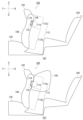
- Fig. 1(a) is a diagram illustrating a state before the airbag device 100 is activated.
- the airbag device 100 of this embodiment is installed in a seat back 106 of a front seat 102 as an example of a seat, and is embodied as a restraint device for restraining a rear seat occupant seated in a rear seat 104 from the front.
- the seat can be rotated forward and backward inside the vehicle, and the forward and backward direction of the seat may not coincide with the forward and backward direction of the vehicle, so the directions used in the following explanation are mainly assumed to be based on the seat.
- the forward and backward directions of the front seat 102 in the standard position are illustrated by arrows F (Forward) and B (Back)
- the left and right width directions of the front seat 102 are illustrated by arrows L (Left) and R (Right)
- the vertical directions of the vehicle are illustrated by arrows U (Up) and D (Down).
- upward refers to the direction of the head of an occupant normally seated in the seat
- downward refers to the direction of the lower legs of the occupant.
- front side the side that comes into contact with the front seat occupant seated in the front seat 102
- back side the side opposite the front seat occupant
- the airbag cushion 108 of the airbag device 100 is rolled or folded into a small storage form before activation and is stored in a storage section 110.
- the storage section 110 is installed in a seat back section 112 that forms the back of the seat back 106 of the front seat 102, with an opening 114 facing the rear seat 104 at the rear.
- An inflator 116 which is a gas generating device, is also installed inside the storage section 110.
- the inflator 116 is a device that supplies gas to the airbag cushion 108, and in this embodiment, a disk-shaped inflator is used.
- Currently popular inflators include types that are filled with a gas generating agent and burn this to generate gas, types that are filled with compressed gas and supply gas without generating heat, and hybrid types that use both combustion gas and compressed gas. Any type can be used as the inflator 116.
- FIG. 1(b) is a diagram illustrating the state after the airbag device 100 has been activated.
- the airbag device 100 activates when a frontal collision is predicted or detected by various sensors.
- the inflator 116 is activated by receiving a signal from a control unit (not shown) and ejects gas.
- the pressure of the gas supplied from the inflator 116 causes the airbag cushion 108 to split open the lid of the storage compartment, and the airbag cushion 108 inflates and deploys toward the rear seat.
- the airbag cushion 108 inflates and deploys between the seat back 112 of the seat back 106 of the front seat 102 and the rear seat occupant seated in the rear seat 104 behind the front seat 102, restraining the rear seat occupant from the front and preventing the rear seat occupant from moving forward.
- FIG. 2 is a perspective view illustrating the airbag cushion 108 of FIG. 1(b) alone.
- FIG. 2(a) is a perspective view of the airbag cushion 108 of FIG. 1(b) as seen from the rear left side.
- the airbag cushion 108 has a shape close to a cube when seen from the rear, and mainly uses the rear cushion rear surface portion 126 on the rear side to support the body of the rear seat occupant.
- FIG. 2(b) is a perspective view of the airbag cushion 108 in FIG. 1(b) as seen from the front left side.
- a gas receiver 120 is provided on the lower part of the cushion front surface 118 on the front side of the airbag cushion 108.
- the gas receiver 120 is connected to the inflator 116 (shown) and receives gas from the inflator 116.
- Figure 3 is a side view of the airbag cushion 108 in Figure 2(a).
- the dimensions of the cushion rear surface 126 of the airbag cushion 108 are larger in the vertical direction than the cushion front surface 118, and the airbag cushion 108 has a shape in which the vertical dimensions gradually increase toward the rear as viewed overall.
- the cushion front surface portion 118 is the portion that forms the front surface of the airbag cushion 108, and extends vertically along the seat back surface portion 112 (see FIG. 1(b)).
- the cushion upper surface portion 122 is the portion that forms the upper surface of the airbag cushion 108, and extends rearward from the upper end of the cushion front surface portion 118.
- the cushion lower surface portion 124 is the portion that forms the lower surface of the airbag cushion 108, and extends rearward from the lower end of the cushion front surface portion 118.
- the cushion rear surface portion 126 is the portion that forms the rear surface of the airbag cushion 108, and connects the rear end of the cushion upper surface portion 122 and the rear end of the cushion lower surface portion 124 in the vertical direction.
- the airbag cushion 108 When viewed from the side, the airbag cushion 108 is shaped so that the angle ⁇ 1 between the tangent L1 to the cushion top surface 122 and the tangent L2 to the cushion rear surface 126 is an acute angle (0° ⁇ 1 ⁇ 90°).
- the upper corner 128 on the upper rear side of the airbag cushion 108 formed by the cushion top surface 122 and the cushion rear surface 126 is formed to be an acute angle.
- the cushion front portion 118 is shaped to conform to the seat back portion 112 of the seat back 106 (see FIG. 1(b)).
- the seat back portion 112 is a portion that forms the back of the seat back 106 of the front seat 102 of the vehicle.
- the seat back portion 112 is formed to include an upper back upper portion 112a and a lower back curved portion 112b.
- the upper back surface 112a in FIG. 1(b) is a portion formed near the upper end of the seat back 106, and is the back surface of the portion that supports the shoulders of a front seat occupant seated in the front seat 102.
- the upper back surface 112a extends in the vertical direction when the seat back 106 is at the standard angle.
- the curved back portion 112b is the back portion that mainly supports the back and waist of the front seat occupant, and extends downward toward the seat cushion 130 while curving forward from the upper back portion 112a.
- the cushion front portion 118 in FIG. 3 is formed to include an upper front upper portion 118a, which is a flat portion, and a lower front bulge portion 118b, which is a bulge portion.
- the front upper portion 118a extends linearly along the back upper portion 112a of the seat back portion 112 (see FIG. 1(b)).
- the front bulge 118b is formed below the front upper part 118a and bulges forward from the front upper part 118a along the rear curved part 112b (see FIG. 1(b)).
- the front bulge 118b is formed mainly in the range below the center in the up-down direction of the cushion front part 118.
- the front bulge 118b is formed to bulge forward including the lower end of the cushion front portion 118, but the central portion of the lower half of the cushion front portion 118 that does not include the lower end may be formed to bulge forward.
- the seat back portion 112 of the seat bag 106 generally has an upper back upper portion 112a that bulges rearward compared to the lower back curved portion 112b.
- the upper front upper portion 118a of the cushion front portion 118 of the airbag cushion 108 is recessed rearward compared to the lower front bulge portion 118b.
- the gas receiving section 120 in FIG. 2(b) is provided on the upper part of the front bulge 118b and is connected to the inflator 116 (FIG. 1(b)), which is a gas supply section.
- the inflator 116 FIG. 1(b)
- the front upper part 118a is retracted rearward compared to the front bulge 118b, and the front upper part 118a is prevented from excessively pressing the back upper part 112a of the seat back part 112.
- the gas receiving section 120 is provided on the upper part of the front bulge 118b, when gas is received from the gas receiving section 120, the upper front upper part 118a and the lower front bulge 118b come into contact with each other along the back upper part 112a and the back curved part 112b, as viewed from the gas receiving section 120.
- the airbag cushion 108 is able to inflate and deploy with a more stable behavior by suppressing up-down and front-back rocking.
- the gas supply section is directly connected to the inflator 116 and the airbag cushion 108, and the gas supply section that supplies gas to the airbag cushion 108 is formed by the inflator 116 itself.
- the inflator 116 is provided at the bottom of the upper back portion 112a or at the top of the curved back portion 112b, and supplies gas directly to the airbag cushion 108 from there.
- the inflator 116 provided in this position provides a gas supply section that can efficiently supply gas to the upper back portion 112a of the seat back 106 and the airbag cushion 108, which is shaped to fit the curved back portion.
- the gas supply unit is realized by installing the inflator 116 in the seat back portion 112 of the seat back 106, but the configuration of the gas supply unit is not limited to this.
- a configuration in which the inflator is provided at the bottom of the curved back portion 112b of the seat back 106, a pipe-shaped gas guide is extended from there, and its outlet is provided at the upper back portion 112a as the gas supply unit can also be adopted.
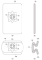
- FIG. 4 is an exploded view of the panels that form the airbag cushion 108 in FIG. 2(b). Each panel illustrated in FIG. 4 is the inner surface of the airbag cushion 108.
- the airbag cushion 108 is composed of a central main panel 132 and a pair of left and right side panels 134a, 134b.
- the side panels 134a, 134b are provided as a pair symmetrically on the left and right sides of the width direction of the airbag cushion 108 (see FIG. 2(a)) and form both sides of the airbag cushion 108 in the width direction.
- the main panel 132 is in the shape of a long strip, and the edges of the pair of side panels 134a, 134b are connected to each other by sewing or the like. The ends on both sides of the length of the main panel 132 are joined to each other by sewing or the like.
- the main panel 132 forms the cushion front surface 118, the cushion upper surface 122, the cushion lower surface 124, and the cushion rear surface 126.
- the main panel 132 is provided with a gas receiving section 120 that is connected to the inflator 116 (see FIG. 1(b)).
- the gas receiving section 120 has a through hole 136 formed in the center, into which part of the inflator 116 is inserted, and is provided with a number of bolt holes 138 around the through hole 136, into which the stud bolts of the inflator 116 are inserted.
- the gas receiving section 120 is connected to the insole of the storage section 110, for example, by using the bolt holes 138, with part of the inflator 116 inserted.
- the airbag cushion 108 can be realized with a simpler panel configuration using a total of three panel members: the main panel 132 and a pair of side panels 134a, 134b.
- FIG. 5 is a diagram illustrating the process of folding the airbag cushion 108 of FIG. 2(b).
- FIG. 5(a) is a diagram showing the airbag cushion 108 of FIG. 2(b) folded in the front-rear direction.
- the airbag cushion 108 is first compressed in the front-rear direction to form the stored form.
- FIG. 5(b) is a side view of the airbag cushion 108 in FIG. 5(b).
- the airbag cushion 108 is compressed in the front-to-rear direction and folded into a vertically elongated shape.
- FIG. 5(c) shows the airbag cushion 108 of FIG. 5(a) folded vertically.
- the airbag cushion 108 is folded at its upper and lower parts toward the gas receiving portion 120 to form a compressed storage form.
- Fig. 5(d) is a side view of the airbag cushion 108 in Fig. 5(c).
- the airbag cushion 108 in the stored form has an upper folded portion 140a formed by rolling or folding the upper side above the gas receiving portion 120 toward the gas receiving portion 120, and a lower folded portion 140b formed by rolling or folding the lower side below the gas receiving portion 120 toward the gas receiving portion 120.
- FIG. 6 is a diagram illustrating the process of the airbag cushion 108 inflating and deploying in the stored form of FIG. 5(d).
- FIG. 6(a) is a diagram illustrating the state before the airbag device 100 is activated.
- the airbag cushion 108 has the upper folded portion 140a stored above the inflator 116, and the lower folded portion 140b stored below the inflator 116.
- FIG. 6(b) is a diagram illustrating the state in which the airbag device 100 in FIG. 6(a) is activated.
- the inflator 116 When the inflator 116 is activated, gas is supplied to the airbag cushion 108, causing the internal pressure to rise, and the airbag cushion 108 inflates rearward while tearing open the lid of the storage section 110.
- FIG. 6(c) is a diagram illustrating an example of an advanced state of operation of the airbag device 100 of FIG. 6(b).
- the central section 142 inflates rearward, while the upper folded section 140a inflates upward, and the lower folded section 140b inflates downward.
- FIG. 6(d) is a diagram illustrating a state in which the operation of the airbag device 100 of FIG. 6(c) has progressed further. Following FIG. 6(c), the airbag cushion 108 expands and deploys such that the vertical center portion 142 is inflated toward the rear seat occupant, while the upper folded portion 140a and the lower folded portion 140b are deployed upward and downward, respectively.
- the airbag cushion 108 in the stored configuration is provided with the upper folded portion 140a and the lower folded portion 140b, which allows the occupant to be restrained and quickly contacted with the seat back portion 112 of the seat back 106 of the front seat 102 (see FIG. 1(b)).
- Figure 7 illustrates the process in which the airbag cushion 108 in Figure 1(b) restrains the occupant 150.
- Figure 7(a) illustrates the state of the airbag cushion 108 immediately after it is inflated and deployed.
- Occupant 150 is an example of the AF05, one of the Hybrid III dummies used in automobile frontal collision tests.
- AF05 is a dummy modeled after a petite female, with a height of 145 cm, seated height of 79 cm, and weight of approximately 45 kg. All dummy models, including the AF05 dummy, are created based on the standards of the National Highway Traffic Safety Administration (NHTSA).
- NHSA National Highway Traffic Safety Administration
- the storage section 110 and airbag cushion 108 of the airbag device 100 are configured so that the airbag cushion 108 inflates and deploys to a position above the knees 152 of a small-sized female occupant 150 seated in a normal position in the rear seat 104.
- the airbag cushion 108 is installed at a height that allows it to inflate and deploy smoothly without interfering with the legs of the occupant 150.
- the airbag cushion 108 is installed so that the upper corner 128 is located approximately in front of the head 154 of the occupant 150. This allows the occupant 150 to come into contact with the airbag cushion 108 from the upper corner 128.
- the cushion rear surface 126 is set to be approximately parallel to the chest 156 of the occupant 150 when viewed from the side, making it possible to suppress deflection of the chest 156 of the occupant 150.
- FIG. 7(b) is a diagram illustrating the state in which the occupant 150 in FIG. 7(a) has entered the airbag cushion 108.
- the airbag cushion 108 restrains and protects the occupant 150 from the front.
- the cushion front surface 118 comes into surface contact with the seat back surface 112
- the cushion bottom surface 124 comes into surface contact with the thighs 158 of the occupant 150.
- the airbag cushion 108 inflates and deploys to fill the space between the seat back surface 112 and the thighs 158 of the occupant 150 and the upper body, thereby fully supporting the body of the occupant 150 and efficiently absorbing the kinetic energy of the occupant 150 in an emergency.
- the airbag cushion 108 of this embodiment is formed such that the shape of the front upper portion 118a and front bulge portion 118b of the cushion front portion 118 conforms to the shape of the back upper portion 112a and back curved portion 112b of the seat back 106 of the front seat 102. Therefore, when the rear seat occupant 150 comes into contact with the airbag cushion 108 from behind, the cushion front portion 118 comes into wide surface contact with the seat back portion 112 of the seat back 106 of the front seat 102, thereby obtaining a reaction force from the seat back portion 112 and making it possible to restrain the rear seat occupant 150 while maintaining a more stable posture.
- the front upper portion 118a on the upper side of the cushion front portion 118 is shaped to be retreated further rearward than the lower front bulge portion 118b.
- the airbag cushion 108 has an acute upper corner 128, which makes it easier for the head 154 of the occupant 150 to come into contact with the upper corner 128.
- the front bulge 118b described above is provided diagonally from the upper corner 128. With this configuration, the airbag cushion 108 distributes the load of the occupant 150 applied from the upper corner 128 to the seat back 106 by the front bulge 118b, making it possible for the airbag cushion 108 to efficiently absorb the load received from the rear seat occupant 150.
- the airbag cushion 108 uses the seat back surface 112 and the thighs 158 of the rear seat occupant 150 as reaction surfaces, making it possible to restrain the head 154 and upper body of the rear seat occupant 150 in a more stable position.
- FIG. 8 illustrates a relationship between the occupant 160 and the airbag cushion 108 that is different from that in FIG. 7.
- FIG. 8(a) illustrates the airbag cushion 108 and the occupant 160 in a manner that corresponds to FIG. 7(a).
- Occupant 160 is an example of an AM95 dummy, one of the Hybrid III dummies, which are human dummies used in automobile frontal collision tests.
- the AM95 dummy is a human dummy modeled after a large American adult male, with a height of 183 cm, a seated height of 94 cm, and a weight of approximately 101 kg.
- the storage section 110 and airbag cushion 108 of the airbag device 100 can also be configured to inflate and deploy the airbag cushion 108 at a position above the knees 162 of a large male occupant 160 seated in a normal position in the rear seat 104.
- FIG. 8(b) is a diagram illustrating the state in which the occupant 160 in FIG. 8(a) has entered the airbag cushion 108. Even when restraining the occupant 160, the airbag cushion 108 is capable of fully supporting the body of the occupant 160 and efficiently absorbing the kinetic energy by having the cushion front surface 118 in surface contact with the seat back surface 112 and the cushion bottom surface 124 in surface contact with the thighs 164 of the occupant 160.
- the airbag cushion 108 of this embodiment can be installed to accommodate occupants of various builds, such as the female occupant 150 in FIG. 7 and the male occupant 160 in FIG. 8. Furthermore, by setting the installation position based on the height of the seat cushion of the rear seat 104, the airbag cushion 108 can exert its restraint performance even for occupants of different builds, such as the occupant 150 and the occupant 160.
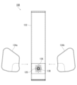
- Second Embodiment 9 is a diagram illustrating an example of an outline of a vehicle rear seat occupant protection device (hereinafter, knee airbag device 200) according to a second embodiment of the present invention.
- the vehicle rear seat occupant protection device is implemented as a knee airbag device 200 that restrains knees 232 of an occupant (see FIG. 12) in a rear seat 204 from the front.
- FIG. 9(a) is a diagram illustrating the knee airbag device 200 before it is activated.
- the knee airbag device 200 of this embodiment is installed in the seat back 206 of the front seat 202.
- FIG. 9(b) is a diagram illustrating the state after the knee airbag device 200 has been activated.
- the knee airbag device 200 activates when a frontal collision is predicted or detected by various sensors, and inflates and deploys the airbag cushion 208.
- FIG. 10 is a diagram illustrating the airbag cushion 208 of FIG. 9(b) alone.
- FIG. 10(a) is a perspective view of the airbag cushion 208 of FIG. 9(b) as viewed from the rear left side.
- the airbag cushion 208 mainly utilizes the rear cushion rear surface portion 210 on the rear side to restrain the area from the knees 232 to the shins 234 of the occupant 230 in the rear seat 204 (see FIG. 12).
- the cushion rear surface portion 210 is set to a width that corresponds to the seating area of the occupant 230 in the rear seat 204.
- Figure 10(b) is a perspective view of the airbag cushion 208 in Figure 9(b) as seen from the front left side.
- the cushion front surface 212 on the front side of the airbag cushion 208 is set to a width according to the seat back surface 214 (see Figure 12) in order to come into contact with the seat back surface 214.
- the airbag cushion 208 has belt-shaped auxiliary members 216, 217. There are two auxiliary members 216, 217 in total, which apply tension to suppress the oscillation or movement of the airbag cushion 208. One end 216a, 217a of the auxiliary members 216, 217 is connected to the cushion underside 220, and the other end 216b, 217b is connected to the inside of the storage section 110 of the seat back 214.
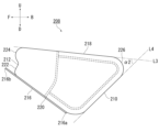
- FIG. 11 is a side view of the airbag cushion 208 in FIG. 10(b).
- the airbag cushion 208 has a shape in which the dimensions of the cushion rear surface 210 are larger in the vertical direction than the cushion front surface 212, and the overall dimensions of the cushion gradually increase in the vertical direction toward the rear.
- the cushion front portion 212 forms the front surface of the airbag cushion 208 and inflates and deploys along the seat back portion 214 (see Figure 12).
- the cushion upper surface portion 218 forms the upper surface of the airbag cushion 208 and extends slightly downward from the upper end of the cushion front surface portion 212 toward the rear.
- the cushion underside portion 220 forms the underside of the airbag cushion 208 and extends downward toward the rear from the lower end of the cushion front side portion 212.
- the cushion rear surface portion 210 is a portion that forms the rear surface of the airbag cushion 208, and vertically connects the rear end of the cushion upper surface portion 218 to the rear end of the cushion lower surface portion 220.
- the cushion rear surface portion 210 extends from the cushion upper surface portion 218 toward the cushion lower surface portion 220 while slanting forward.
- the cushion front surface 212 is formed with a flat portion 222 and a bulge portion 224.
- the flat portion 222 is a flat area formed on the lower side of the cushion front surface 212, and is provided with the gas receiving portion 120 (see FIG. 10(b)).
- the bulge 224 is formed on the upper side of the cushion front surface 212, and bulges forward more than the flat portion 222.
- the upper side of the cushion front surface 212 where the bulge 224 is present presses more firmly against the seat back surface 214 (see FIG. 12). Therefore, when restraining the occupant 230, the airbag cushion 208 is able to suppress upward rotational movement around the gas receiving portion 120 as a fulcrum.
- the cushion rear surface 210 extends along the shins 234 of the occupant 230 seated properly in the rear seat 204.
- the above-mentioned bulges 224 are provided at the diagonal corners of the cushion rear surface 210, so the airbag cushion 208 distributes the load received from the cushion rear surface 210 from the bulges 224 to the seat back surface 214, making it possible to restrain the shins 234 of the occupant 230 while maintaining a stable posture.
- the airbag cushion 208 When viewed from the side, the airbag cushion 208 is shaped so that the angle ⁇ 2 between the tangent L3 of the cushion upper surface 218 and the tangent L4 of the cushion rear surface 210 is an acute angle (0° ⁇ 2 ⁇ 90°).
- the upper corner 226 on the rear upper side of the airbag cushion 208 formed by the cushion upper surface 218 and the cushion rear surface 210 is formed to be an acute angle.
- the cushion rear surface 210 can be deployed parallel to the shins 234 of the occupant 230 in the rear seat 204, making it possible to widely restrain the shins 234 of the occupant 230.
- the auxiliary members 216, 217 deploy along the cushion underside 220.
- the auxiliary member 216 as an example, one end 216a of the auxiliary member 216 is connected to the cushion rear side 210 side of the cushion underside 220, and the other end 216b is connected inside the storage section 110 of the seat back surface 214.
- the tension of the auxiliary members 216, 217 can be transmitted to the cushion rear side 210 side of the airbag cushion 208, making it possible to efficiently suppress the rocking of the airbag cushion 208.
- FIG. 12 is a diagram illustrating the process in which the airbag cushion 208 in FIG. 9(b) restrains the occupant 230.
- the occupant 230 can be anyone from a small-sized woman to a large-sized man, similar to the occupant 150 in FIG. 7(a) and the occupant 160 in FIG. 8(a).
- the storage section 110 and airbag cushion 208 of the knee airbag device 200 are configured so that the airbag cushion 208 inflates and deploys toward the knees 232 of an occupant 230 seated in the correct position in the rear seat 204.
- the airbag cushion 208 is installed so that the upper corner 226 is positioned slightly above the knee 232 of the occupant 230.
- the rear surface 210 of the cushion is set so that it is roughly parallel to the area from the knee 232 to the shin 234 of the occupant 230 when viewed from the side.
- the knees 232 of the occupant 230 enter the cushion rear surface portion 210.
- the cushion front surface portion 212 comes into contact with the seat rear surface portion 214 of the airbag cushion 208, absorbing the load from the occupant 230 and restraining the occupant 230.
- the airbag cushion 208 inflates and deploys so that the rear cushion portion 210 is parallel to the area from the knees 232 to the shins 234 of the occupant 230, fully supporting the area around the knees 232 of the occupant 230 and efficiently absorbing the kinetic energy of the occupant 230 in an emergency.
- the airbag cushion 208 has a bulge 224 on the cushion front surface 212 located above the flat portion 222. Therefore, when the knees 232 of the occupant 230 come into contact with the cushion rear surface 210, the bulge 224 on the upper side of the cushion front surface 212 presses against the seat rear surface 214. This makes it possible for the airbag cushion 208 to suppress upward rotational movement centered around the vicinity of the inflator 116.
- the auxiliary members 216, 217 not only suppress the vertical shaking of the airbag cushion 208 when it is inflated and deployed, but also suppress the upward movement of the airbag cushion 208 when an occupant is restrained.
- the auxiliary members 216, 217 stabilize the posture of the airbag cushion 208 when an occupant is restrained, and prevent the occupant 230 from moving toward the front seat 202. Therefore, according to this embodiment, it is possible to realize a rear seat occupant protection device for a vehicle with improved occupant restraint performance.
- the auxiliary members 216, 217 can also be applied to the cushion underside 124 of the airbag cushion 108 in FIG. 3.
- the airbag cushion 108 also has the auxiliary members 216, 217 stretched between the cushion underside 124 and the vicinity of the storage section 110, making it possible to suppress vertical rocking when inflated and deployed, and upward movement when an occupant is restrained.
- the present invention can be used in a vehicle rear seat occupant protection device that restrains rear seat occupants.
Landscapes
- Engineering & Computer Science (AREA)
- Mechanical Engineering (AREA)
- Aviation & Aerospace Engineering (AREA)
- Transportation (AREA)
- Air Bags (AREA)
Priority Applications (4)
| Application Number | Priority Date | Filing Date | Title |
|---|---|---|---|
| EP24778839.1A EP4691859A1 (en) | 2023-03-31 | 2024-02-19 | Vehicle rear seat occupant protection device |
| CN202480022951.0A CN121057677A (zh) | 2023-03-31 | 2024-02-19 | 车辆后座乘员保护装置 |
| JP2025509922A JPWO2024202694A1 (https=) | 2023-03-31 | 2024-02-19 | |
| KR1020257032960A KR20250159221A (ko) | 2023-03-31 | 2024-02-19 | 차량 뒷좌석 승차인 보호 장치 |
Applications Claiming Priority (2)
| Application Number | Priority Date | Filing Date | Title |
|---|---|---|---|
| JP2023057758 | 2023-03-31 | ||
| JP2023-057758 | 2023-03-31 |
Publications (1)
| Publication Number | Publication Date |
|---|---|
| WO2024202694A1 true WO2024202694A1 (ja) | 2024-10-03 |
Family
ID=92905063
Family Applications (1)
| Application Number | Title | Priority Date | Filing Date |
|---|---|---|---|
| PCT/JP2024/005768 Ceased WO2024202694A1 (ja) | 2023-03-31 | 2024-02-19 | 車両後席乗員保護装置 |
Country Status (5)
| Country | Link |
|---|---|
| EP (1) | EP4691859A1 (https=) |
| JP (1) | JPWO2024202694A1 (https=) |
| KR (1) | KR20250159221A (https=) |
| CN (1) | CN121057677A (https=) |
| WO (1) | WO2024202694A1 (https=) |
Citations (10)
| Publication number | Priority date | Publication date | Assignee | Title |
|---|---|---|---|---|
| JPH04356239A (ja) * | 1991-05-31 | 1992-12-09 | Aisin Seiki Co Ltd | シート |
| JPH09142240A (ja) * | 1995-11-24 | 1997-06-03 | Ikeda Bussan Co Ltd | 後席用エアバッグ装置 |
| JPH09175300A (ja) * | 1995-12-25 | 1997-07-08 | Bridgestone Corp | 助手席用エアバッグおよびその裁断方法 |
| CN202283906U (zh) | 2011-08-31 | 2012-06-27 | 长城汽车股份有限公司 | 一种保护后排乘员的汽车安全气囊 |
| JP2016074405A (ja) * | 2014-10-07 | 2016-05-12 | 現代自動車株式会社Hyundai Motor Company | 車両用後席エアバッグ装置およびその制御方法 |
| JP2019064345A (ja) * | 2017-09-29 | 2019-04-25 | マツダ株式会社 | エアバッグ装置 |
| JP2019196157A (ja) * | 2018-05-11 | 2019-11-14 | 三菱自動車工業株式会社 | 後席乗員保護装置 |
| JP2021511258A (ja) * | 2018-02-28 | 2021-05-06 | オートリブ エー・エス・ピー・インク | 調節可能なヘッドレスト及び一体型後部シートエアバッグを有する車両用シート |
| JP2022030821A (ja) * | 2020-08-07 | 2022-02-18 | トヨタ自動車株式会社 | 乗員保護装置及び車両用シート |
| JP2022100500A (ja) * | 2020-12-24 | 2022-07-06 | 豊田合成株式会社 | エアバッグ装置 |
-
2024
- 2024-02-19 CN CN202480022951.0A patent/CN121057677A/zh active Pending
- 2024-02-19 EP EP24778839.1A patent/EP4691859A1/en active Pending
- 2024-02-19 JP JP2025509922A patent/JPWO2024202694A1/ja active Pending
- 2024-02-19 KR KR1020257032960A patent/KR20250159221A/ko active Pending
- 2024-02-19 WO PCT/JP2024/005768 patent/WO2024202694A1/ja not_active Ceased
Patent Citations (10)
| Publication number | Priority date | Publication date | Assignee | Title |
|---|---|---|---|---|
| JPH04356239A (ja) * | 1991-05-31 | 1992-12-09 | Aisin Seiki Co Ltd | シート |
| JPH09142240A (ja) * | 1995-11-24 | 1997-06-03 | Ikeda Bussan Co Ltd | 後席用エアバッグ装置 |
| JPH09175300A (ja) * | 1995-12-25 | 1997-07-08 | Bridgestone Corp | 助手席用エアバッグおよびその裁断方法 |
| CN202283906U (zh) | 2011-08-31 | 2012-06-27 | 长城汽车股份有限公司 | 一种保护后排乘员的汽车安全气囊 |
| JP2016074405A (ja) * | 2014-10-07 | 2016-05-12 | 現代自動車株式会社Hyundai Motor Company | 車両用後席エアバッグ装置およびその制御方法 |
| JP2019064345A (ja) * | 2017-09-29 | 2019-04-25 | マツダ株式会社 | エアバッグ装置 |
| JP2021511258A (ja) * | 2018-02-28 | 2021-05-06 | オートリブ エー・エス・ピー・インク | 調節可能なヘッドレスト及び一体型後部シートエアバッグを有する車両用シート |
| JP2019196157A (ja) * | 2018-05-11 | 2019-11-14 | 三菱自動車工業株式会社 | 後席乗員保護装置 |
| JP2022030821A (ja) * | 2020-08-07 | 2022-02-18 | トヨタ自動車株式会社 | 乗員保護装置及び車両用シート |
| JP2022100500A (ja) * | 2020-12-24 | 2022-07-06 | 豊田合成株式会社 | エアバッグ装置 |
Non-Patent Citations (1)
| Title |
|---|
| See also references of EP4691859A1 |
Also Published As
| Publication number | Publication date |
|---|---|
| CN121057677A (zh) | 2025-12-02 |
| JPWO2024202694A1 (https=) | 2024-10-03 |
| EP4691859A1 (en) | 2026-02-11 |
| KR20250159221A (ko) | 2025-11-10 |
Similar Documents
| Publication | Publication Date | Title |
|---|---|---|
| US11833990B2 (en) | Side airbag device, vehicle seat provided with same, and method for manufacturing side airbag device | |
| US20180222432A1 (en) | Overhead airbag assemblies | |
| US20050151351A1 (en) | Fabric knee airbag for high internal pressures | |
| KR102833529B1 (ko) | 사이드 에어백 장치 | |
| CN113316533A (zh) | 驾驶座安全气囊 | |
| JP7480099B2 (ja) | 乗員拘束装置 | |
| JP7508638B2 (ja) | 運転席用エアバッグ装置 | |
| KR20240146012A (ko) | 차량용 사이드 에어백 장치 | |
| EP4183638B1 (en) | Occupant protection device | |
| JP7808704B2 (ja) | 乗員保護装置 | |
| WO2024202694A1 (ja) | 車両後席乗員保護装置 | |
| JP7792921B2 (ja) | 車両用サイドエアバッグ装置 | |
| JP7684424B2 (ja) | 車両用サイドエアバッグ装置 | |
| JP7381772B2 (ja) | シート内蔵エアバッグ装置 | |
| JP7846594B2 (ja) | 車両用シート | |
| JP7458359B2 (ja) | 車両用サイドエアバッグ装置 | |
| JP6738646B2 (ja) | サイドエアバッグ装置 | |
| CN118339072A (zh) | 车辆用安全气囊装置 | |
| WO2023145244A1 (ja) | 運転席用エアバッグ装置 | |
| WO2025121030A1 (ja) | 車両後席乗員保護用エアバッグ装置 | |
| JP7796883B2 (ja) | サイドエアバッグ装置 | |
| WO2025089097A1 (ja) | 車両用サイドエアバッグ装置 | |
| WO2025225489A1 (ja) | 車両用エアバッグ装置 | |
| JP7519393B2 (ja) | シート内蔵エアバッグ装置 | |
| WO2025089098A1 (ja) | 車両用エアバッグ装置 |
Legal Events
| Date | Code | Title | Description |
|---|---|---|---|
| 121 | Ep: the epo has been informed by wipo that ep was designated in this application |
Ref document number: 24778839 Country of ref document: EP Kind code of ref document: A1 |
|
| WWE | Wipo information: entry into national phase |
Ref document number: 2025509922 Country of ref document: JP |
|
| ENP | Entry into the national phase |
Ref document number: 1020257032960 Country of ref document: KR Free format text: ST27 STATUS EVENT CODE: A-0-1-A10-A15-NAP-PA0105 (AS PROVIDED BY THE NATIONAL OFFICE) |
|
| WWE | Wipo information: entry into national phase |
Ref document number: KR1020257032960 Country of ref document: KR |
|
| WWE | Wipo information: entry into national phase |
Ref document number: 2024778839 Country of ref document: EP |
|
| NENP | Non-entry into the national phase |
Ref country code: DE |
|
| ENP | Entry into the national phase |
Ref document number: 2024778839 Country of ref document: EP Effective date: 20251031 |
|
| ENP | Entry into the national phase |
Ref document number: 2024778839 Country of ref document: EP Effective date: 20251031 |
|
| ENP | Entry into the national phase |
Ref document number: 2024778839 Country of ref document: EP Effective date: 20251031 |
|
| ENP | Entry into the national phase |
Ref document number: 2024778839 Country of ref document: EP Effective date: 20251031 |
|
| ENP | Entry into the national phase |
Ref document number: 2024778839 Country of ref document: EP Effective date: 20251031 |
|
| ENP | Entry into the national phase |
Ref document number: 2024778839 Country of ref document: EP Effective date: 20251031 |
|
| ENP | Entry into the national phase |
Ref document number: 2024778839 Country of ref document: EP Effective date: 20251031 |
|
| ENP | Entry into the national phase |
Ref document number: 2024778839 Country of ref document: EP Effective date: 20251031 |
|
| WWP | Wipo information: published in national office |
Ref document number: 2024778839 Country of ref document: EP |