WO2024201847A1 - 車両の荷箱構造 - Google Patents
車両の荷箱構造 Download PDFInfo
- Publication number
- WO2024201847A1 WO2024201847A1 PCT/JP2023/012986 JP2023012986W WO2024201847A1 WO 2024201847 A1 WO2024201847 A1 WO 2024201847A1 JP 2023012986 W JP2023012986 W JP 2023012986W WO 2024201847 A1 WO2024201847 A1 WO 2024201847A1
- Authority
- WO
- WIPO (PCT)
- Prior art keywords
- strut
- vehicle
- surface portion
- reinforcement
- panel
- Prior art date
- Legal status (The legal status is an assumption and is not a legal conclusion. Google has not performed a legal analysis and makes no representation as to the accuracy of the status listed.)
- Ceased
Links
Images




Classifications
-
- B—PERFORMING OPERATIONS; TRANSPORTING
- B62—LAND VEHICLES FOR TRAVELLING OTHERWISE THAN ON RAILS
- B62D—MOTOR VEHICLES; TRAILERS
- B62D33/00—Superstructures for load-carrying vehicles
- B62D33/02—Platforms; Open load compartments
- B62D33/023—Sideboard or tailgate structures
Definitions
- This case concerns the structure of a vehicle's cargo box.
- a structure in which the side gate (side panel, side plate, side gate) of the cargo box is reinforced with struts.
- a strut is a "column-shaped part" and is formed, for example, so that its horizontal cross-sectional shape is nearly closed.
- the position of the strut is set according to the strength, rigidity, and use required of the cargo box, and is disposed, for example, at the front or rear end of the side gate (see Patent Document 1).
- Providing struts can improve the strength and rigidity of the side gate against vertical loads.
- the reinforcing performance of the strut may not be sufficient for horizontal loads, depending on the magnitude and position of the load.
- luggage placed on the cargo box may apply a load to the upper end of the side gate toward the outside of the turn.
- deformation may occur in which the entire strut rotates outward around the base end of the strut.
- deformation may occur in which the entire strut rotates inward. It is desirable to suppress these lateral rotational deformations as much as possible in order to improve the robustness (performance, quality, durability, etc.) of the cargo box.
- One of the objectives of this case was devised in light of the above-mentioned problems, and is to provide a cargo box structure for a vehicle that can improve the robustness of the cargo box with a simple configuration.
- this objective is not the only objective, and another objective of this case is to achieve effects that cannot be obtained with conventional technology, which are derived from the various configurations shown in the "Mode for Carrying Out the Invention" described below.
- the disclosed vehicle cargo box structure can be realized as the embodiments (application examples) disclosed below, which solve at least part of the above problems.
- Each embodiment from embodiment 2 onwards is an embodiment that can be selected additionally as appropriate, and each is an embodiment that can be omitted. None of the embodiments from embodiment 2 onwards discloses an embodiment or configuration that is essential to the present case.
- the disclosed vehicle cargo box structure includes a cargo box floor panel, side panels erected on both outer sides of the floor panel in the vehicle width direction, and columnar struts attached to the side panels and extending vertically relative to the floor panel.
- This structure includes a planar reinforcement that is suspended downward from the floor panel and extends across the vehicle width direction, and a bracket that connects the strut and the reinforcement.
- the bracket also has a horizontal extension portion that extends in the extension direction of the reinforcement and is connected to the reinforcement, and a vertical extension portion that extends vertically beyond the horizontal extension portion and is connected to the strut.
- the strut has an inclined surface portion that faces in the vehicle longitudinal direction and inward in the vehicle width direction along the vertical direction
- the bracket is formed in a surface shape in which the vertical extension portion is inclined forward and backward based on the horizontal extension portion in accordance with the inclination of the inclined surface portion, and the vertical extension portion is joined in a state overlapping the inclined surface portion.
- the vertically extending portion extends to the vicinity of a lower end of the strut and is fixed to the strut at a plurality of locations spaced apart in the up-down direction.
- the laterally extending portion preferably has an outer joint portion that is joined to the reinforcement at a position near the outer end of the reinforcement in the vehicle width direction, and an inner joint portion that is joined to the laterally extending portion at a position near the inner end of the laterally extending portion in the vehicle width direction separated from the outer joint portion in the extension direction of the reinforcement.
- the strut is disposed at the rear end of the side panel, and that the rear end of the cargo box is provided with a rear end panel that is formed with an L-shaped cross section and extends in the vehicle width direction, and has a horizontal surface portion that is connected to the floor panel and a vertical surface portion that extends downward from the rear end of the horizontal surface portion.
- the reinforcement is located in front of the rear end panel, attached to the horizontal surface portion or the floor panel, and connected to the vertical surface portion via a connecting member.
- the structure further includes an auxiliary bracket that connects the strut to the outer end of the rear end panel in the vehicle width direction. It is also preferable that the auxiliary bracket has a rear surface portion that is connected to the vertical surface portion, an upper surface portion that is connected to the horizontal surface portion, and a side surface portion that is connected to the inner surface portion of the strut that faces inward in the vehicle width direction.
- the strut has a strut outer that is a portion at the rear end of the side panel that houses the tail lamp unit of the vehicle and forms a storage space for the tail lamp unit between the strut outer and an outer panel that forms the exterior of the side panel.
- the strut outer has a front portion that faces the front of the strut, an inner portion that faces the inside of the strut in the vehicle width direction, and an inclined surface portion that faces the vehicle front-rear direction and the inside of the vehicle width direction along the vertical direction and is formed so as to connect the front portion and the inner portion.
- the bracket connects the strut outer and the reinforcement in the vehicle width direction.
- the bracket has an oblique reinforcing portion that obliquely connects an inside corner portion between the horizontally extending portion and the vertically extending portion in a front view.
- Aspect 9 it is preferable that the bracket is formed in a funnel shape expanding in the up-down direction from the horizontal extending portion toward the vertical extending portion in a front view.
- the vertically extending portion of the bracket that extends in the up-down direction is fixed to a strut provided on the side panel, thereby ensuring the distance (vertical distance) between the center of rotation during lateral deformation of the side panel and the fixed points of the strut and bracket.
- This makes it possible to efficiently prevent the side panel from lateral collapse.
- the distance (vertical distance) between the center of rotation during flapping deformation of the reinforcement and the fixed points of the strut and bracket can also be ensured, making it possible to efficiently prevent flapping of the reinforcement. Therefore, the robustness of the cargo box can be improved with a simple configuration.
- FIG. 1 is a perspective view of a vehicle to which a luggage box structure according to an embodiment is applied;
- FIG. 2 is a perspective view showing a strut provided on a luggage box of a vehicle.
- 1 is a perspective view of the lower part of the strut viewed from below the floor panel.
- FIG. FIG. 4 is an exploded perspective view of FIG. 3 .
- FIG. FIG. FIG. 4 is a perspective view showing a part of the reinforcement and a connecting member.
- FIG. 4 is a vertical cross-sectional view showing the structure around the rear end panel.
- 1A is a horizontal cross-sectional view of a strut above the floor panel
- FIG. 1B is a horizontal cross-sectional view of a strut below the floor panel.
- 13A and 13B are perspective views showing modified examples of the bracket.
- the disclosed cargo box structure is applied to a vehicle shown in the following embodiment.
- This vehicle is equipped with a cargo box, such as a truck, a pick-up truck, or an SUV (sports utility vehicle).
- the cargo box here refers to a container-shaped area in which luggage is placed.
- the cargo box in this embodiment includes a cargo bed and a luggage compartment.
- the inside of the cargo box (the space in which luggage is placed) may be open to the outside, or it may be a closed space that is not open.
- the floor surface of the cargo box is formed in a nearly flat shape, for example, by a planar floor panel.
- the floor surface may have uneven shapes or ribs to increase surface rigidity.
- side gates side panels, side doors, side gates
- a rear gate rear door, rear gate
- Each of the side gates and rear gates may be provided rotatably relative to the floor panel, or may be fixed so that they cannot be rotated.
- each of the side gates and rear gates may be movable gates that can be opened and closed, or fixed gates that cannot be opened and closed.
- the definition of directions is that the front-rear direction (vehicle length direction) is defined based on the forward and backward direction of the vehicle, and the left-right direction (vehicle width direction) is defined based on the front-rear direction.
- the up-down direction is defined based on the state in which the vehicle is stopped on a flat road surface.
- the vehicle width direction in the part to the left of the vehicle body centerline in a top view of the vehicle, the left is the outside of the vehicle and the right is the inside of the vehicle.
- the right is the outside of the vehicle and the left is the inside of the vehicle.
- the body structure of a vehicle is often formed to be almost symmetrical (mirror symmetry with respect to a plane including the yaw axis and roll axis that pass through the center of gravity of the vehicle), but it does not have to be a completely symmetrical shape.
- FIG. 1 is a perspective view of a vehicle 10 to which a cargo box structure according to an embodiment is applied
- Fig. 2 is a perspective view showing a corner at the left rear end of the vehicle 10.
- the vehicle 10 is provided with a vehicle compartment (cabin) in which passengers board, and a cargo box 11.
- the cargo box 11 is disposed at the rear of the vehicle compartment.
- the vehicle 10 of this embodiment has a ladder frame type chassis structure, and the cargo box 11 is mounted on a ladder frame (not shown).
- the ladder frame is a ladder-shaped frame formed by combining a pair of left and right side members extending in the front-rear direction and a cross member connecting these side members in the left-right direction.
- the cargo box 11 includes a side gate 12 (side panel, side wall), a rear gate 13 , a front panel 14 , a floor panel 15 , a rear bumper 16 , and a tail lamp unit 17 .
- the side gates 12 are wall-like portions that are erected on the left and right end portions of the cargo box 11 on both outer sides in the vehicle width direction of the floor panel 15.
- the side gate 12 is configured by combining an outer panel 18 (side gate outer panel) that forms the exterior of the side gate 12, and an inner panel 19 (side gate inner panel) that is disposed on the inside of the outer panel 18 with a predetermined distance therebetween.
- the outer panel 18 and the inner panel 19 are fixed to each other by, for example, overlapping their edges with each other and welding them together.
- the rear gate 13 is a door-like (wall-like) part that is erected at the rear end of the cargo box 11.
- the rear gate 13 is provided so as to be rotatable in the front-rear direction, for example, around a central axis near the lower end side of the rear gate 13.
- Fig. 2 shows a state in which the rear gate 13 is removed.
- the front panel 14 is a wall-like portion erected at the front end of the cargo box 11.
- the front panel 14 may be omitted, or may be formed integrally with the vehicle interior provided in front of the cargo box 11.
- the floor panel 15 is a flat portion forming the floor surface of the cargo box 11.
- the plate surface of the floor panel 15 is formed with, for example, an uneven shape or ribs for increasing surface rigidity.
- a reinforcing member (such as a cross sill) (not shown) is attached to the underside of the floor panel 15.
- the cargo box 11 is defined by the side gate 12, rear gate 13, front panel 14, and floor panel 15, and has an overall shape of a flat box with an open top.
- the rear bumper 16 is a cushioning member located behind the rear end of the cargo box 11, and is provided so as to connect the rear ends of a pair of left and right side members and extend in the left-right direction.
- the tail lamp unit 17 is a tail light (rear light) device provided at both the left and right ends of the rear end of the cargo box 11.
- a strut 1 is provided at the rear end of the side gate 12 to house the tail lamp unit 17 and reinforce the area around the tail lamp unit 17.
- the strut 1 is a columnar reinforcing structure that extends vertically relative to the floor panel 15.
- the struts 1 are provided in two locations, one on each side of the left and right sides of the rear gate 13, to correspond to the positions of the left and right tail lamp units 17.
- the strut 1 in this embodiment is formed by combining the outer panel 18 of the side gate 12, the inner strut 2, and the outer strut 3, and is formed so that its horizontal cross-sectional shape is approximately a closed cross-section.
- the strut inner 2 is a component that, together with the inner panel 19, forms the interior of the cargo box 11 (the inner surface of the cargo box 11) on the floor panel 15.
- the strut inner 2 is formed into a three-dimensional shape that forms three adjacent faces of a rectangular parallelepiped, for example, and is fixed to the floor panel 15 and the inner panel 19.
- the strut inner 2 shown in Figure 2 has a surface facing forward, a surface facing inward in the vehicle width direction, and a surface facing upward.
- the outer strut 3 is positioned so as to face the outer panel 18 at each of the left and right rear corners of the vehicle 10. Meanwhile, the outer panel 18 has a rearward facing surface and a surface facing outward in the vehicle width direction at each of the left and right rear corners of the vehicle 10. Therefore, by combining the outer panel 18 and the outer strut 3, a closed cross-sectional structure with a horizontal cross-sectional shape that is approximately rectangular is formed.
- the space formed by the outer panel 18 and the outer strut 3 serves as the accommodation space for the tail lamp unit 17.
- a rear end panel 4, a reinforcement 5 (rear end panel reinforcement), and a connecting member 8 are provided at the rear end of the floor panel 15.
- the rear end panel 4 is a member for reinforcing the rear end of the floor panel 15, and extends in the vehicle width direction.
- the rear end panel 4 functions to increase the rigidity near the rear end of the floor panel 15, where the load of the luggage acts first, for example, when the rear gate 13 is opened and luggage is placed on the luggage box 11.
- the rear end panel 4 also has the function of covering and hiding, for example, the small edge of the floor panel 15.
- the rear end panel 4 of this embodiment has an L-shaped (angled) vertical cross section.
- the left-right dimension (width dimension) of the rear end panel 4 corresponds to the left-right dimension of the rear gate 13 (for example, is approximately the same dimension).
- the reinforcement 5 is a planar member for reinforcing the rear end panel 4 and floor panel 15, and is suspended downward from the floor panel 15 and extends across the width of the vehicle.
- the reinforcement 5 is formed in a strip shape that is long in the left-right direction and short in the up-down direction, and the extension direction of the reinforcement 5 is the left-right direction.
- the left-right dimension (width dimension) of the reinforcement 5 corresponds to the left-right dimension of the rear end panel 4 (e.g., approximately the same dimension).
- the reinforcement 5 is disposed in front of the rear end panel 4, and is connected to the rear end panel 4 and floor panel 15 via a connecting member 8.
- the reinforcement 5 extends downward from, for example, a portion of the floor panel 15 that is reinforced by the rear end panel 4.
- the reinforcement 5 may also extend downward from a portion of the rear end panel 4 that is substantially flush with the floor panel 15.
- the reinforcement 5 is defined as a planar member that extends downward from the floor panel 15.
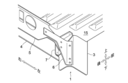
- Fig. 3 is a perspective view showing the state where the lower part of the left strut 1 is looked up from below the floor panel 15, in order to explain the structure of these brackets 6 and 7.
- Fig. 4 is an exploded perspective view showing the various members shown in Fig. 3 in an exploded state. In Figs. 3 and 4, the means (fasteners, etc.) for joining the various members are omitted.
- the bracket 6 is a member that connects the strut outer 3 and the reinforcement 5 that constitute the strut 1 in the vehicle width direction.
- a pair of brackets 6 are provided near both the left and right ends of the reinforcement 5, and function to connect the reinforcement 5 to each of the left and right strut outers 3 below the floor panel 15.
- the auxiliary bracket 7 is a member that connects the strut outer 3 and rear end panel 4 that constitute the strut 1.
- the auxiliary bracket 7 is provided, for example, in pairs near both the left and right ends of the rear end panel 4 (the outer ends in the vehicle width direction), and functions to connect the rear end panel 4 to the left and right strut outers 3 and floor panel 15 below the floor panel 15.
- the bracket 6 and auxiliary bracket 7 are provided in pairs on the left and right, but it is also possible to provide only one on the left or right.
- the strut outer 3 is formed by bending a sheet cut into a predetermined shape. As shown in Figure 4, the strut outer 3 is provided with a front surface portion 31, an inclined surface portion 32, an inner surface portion 33, a rear support portion 34, a front support portion 35, and a second front support portion 36.
- the front portion 31 is a planar portion of the strut 1 that faces the front of the vehicle (forming the front side of the strut 1) and is formed so that its normal is horizontal and faces forward when attached to the vehicle 10.
- the inner surface portion 33 is a planar portion of the strut 1 that faces inward in the vehicle width direction (forming the inner surface of the strut 1) and is formed so that its normal is horizontal and faces inward in the vehicle width direction when attached to the vehicle 10.
- a side portion 71 of the auxiliary bracket 7, described later, is fixed to the inner surface portion 33.
- the inclined surface portion 32 is a planar portion provided between the front portion 31 and the inner surface portion 33, and is formed so that when attached to the vehicle 10, its normal is horizontal and faces in the vehicle longitudinal direction (forward) and inward in the vehicle width direction.
- This inclined surface portion 32 is formed between the front portion 31 and the inner surface portion 33 so as to connect them in the vertical direction.
- the surface orientation of the inclined surface portion 32 is preferably set so that it is inclined at approximately the same angle with respect to the front portion 31 and the inner surface portion 33. In other words, it is preferable to set the surface orientation of the inclined surface portion 32 so that the angle between the front portion 31 and the inclined surface portion 32 is equal to the angle between the inner surface portion 33 and the inclined surface portion 32 in a horizontal cross section.
- a vertical extension portion 62 of the bracket 6, which will be described later, is fixed to the inclined surface portion 32.
- the rear support portion 34 is a flat portion extending from the rear end of the inner surface portion 33 toward the inside in the vehicle width direction.
- the rear support portion 34 is joined to the rear end panel 4 and functions to fix the strut outer 3 to the rear end panel 4.
- the rear surface portion 72 of the auxiliary bracket 7 (described later) is welded and fixed in a triple-layered state to the vertical surface portion 42 of the rear end panel 4 (described later) and the rear support portion 34.
- the front support portion 35 is a flat portion extending forward from the outer end of the front portion 31 in the vehicle width direction.
- the front support portion 35 is fixed or engaged with the inner panel 19 and the outer panel 18. This improves the posture stability of the strut outer 3.
- the front support portion 35 shown in Figure 4 has its front end bent outward in the vehicle width direction, and its tip abuts against the outer panel 18.
- the second front support portion 36 is a planar portion extending from the outer end of the front portion 31 in the vehicle width direction toward the outside in the vehicle width direction.
- the second front support portion 36 is fixed to or engaged with the outer panel 18. This improves the posture stability of the strut outer 3.
- the second front support portion 36 shown in FIG. 4 has its outer end in the vehicle width direction bent toward the rear and in surface contact with the outer panel 18. In this embodiment, the second front support portion 36 is in surface contact with the edge of the mounting opening for the tail lamp unit 17 formed in the outer panel 18.
- the tail lamp unit 17 is also fixed to the outer panel 18 and the second front support portion 36.
- the rear end panel 4 is formed by bending a rectangular steel plate. As shown in FIG. 4, the rear end panel 4 has a horizontal surface portion 41 and a vertical surface portion 42.
- the horizontal surface portion 41 is a planar portion that is connected to the floor panel 15 at the rear end of the cargo box 11.
- An upper surface portion 73 of an auxiliary bracket 7, which will be described later, is fixed to the horizontal surface portion 41.
- the vertical surface portion 42 is a planar portion that extends downward from the rear end of the horizontal surface portion 41.
- a rear surface portion 72 of an auxiliary bracket 7, which will be described later, is fixed to the vertical surface portion 42.
- the angle between the horizontal surface portion 41 and the vertical surface portion 42 is approximately a right angle, and the vertical cross section is L-shaped (angle shape).
- the reinforcement 5 is formed by drilling and bending a sheet metal cut into a predetermined shape. As shown in FIG. 4, the reinforcement 5 has a reinforcing surface 51, an edge 52, and an arm 53.
- the reinforcing surface 51 is a planar portion arranged substantially parallel to the vertical surface 42 of the rear end panel 4.
- the reinforcing surface 51 has a number of openings through which piping and wiring material arranged below the cargo box 11 can be inserted.
- the reinforcement 5 is attached to the horizontal surface 41 or floor panel 15 of the rear end panel 4, and is connected to the vertical surface 42 of the rear end panel 4 via a connecting member 8.
- the edge portion 52 is a planar portion extending forward from the upper end of the reinforcing surface portion 51, and is fixed in surface contact with the horizontal surface portion 41 or the floor panel 15. This means that the reinforcement 5 is attached to the horizontal surface portion 41 or the floor panel 15 in front of the vertical surface portion 42.
- the arm portion 53 is a planar portion extending outward in the vehicle width direction from both the left and right ends of the reinforcing surface portion 51 on the same plane as the reinforcing surface portion 51.
- a lateral extension portion 61 of the bracket 6, described later, is fixed to the arm portion 53.
- the bracket 6 is formed by bending a sheet metal cut into a predetermined shape. As shown in FIG. 4, the bracket 6 is provided with a horizontal extension portion 61, a vertical extension portion 62, and a diagonal reinforcement portion 63.
- the horizontal extension portion 61 is a planar portion that extends in the extension direction of the reinforcement 5 (the left-right direction in this embodiment) and is joined to the reinforcement 5.
- the horizontal extension portion 61 is fastened and fixed in a state of surface contact with the arm portion 53.
- the vertical extension portion 62 is a planar portion that extends further up and down than the horizontal extension portion 61 and is connected to the strut outer 3.
- the vertical dimension of the vertical extension portion 62 is formed to be at least greater than the vertical dimension of the horizontal extension portion 61.
- the vertical extension portion 62 is formed in a shape that extends downward from the outer end of the horizontal extension portion 61 in the vehicle width direction, and extends to the vicinity of the lower end of the strut outer 3.
- the vertical extension portion 62 may be formed in a shape that extends upward from the end of the horizontal extension portion 61, or may be formed in a shape that extends upward and downward from the end of the horizontal extension portion 61.
- the vertical extension portion 62 is formed in a surface shape that is inclined relative to the horizontal extension portion 61 (a surface shape that is not parallel and not perpendicular). While the horizontal extension portion 61 is flat and makes surface contact with the arm portion 53 of the reinforcement 5, the vertical extension portion 62 is formed in a flat shape that makes surface contact with the inclined surface portion 32 of the strut outer 3. When viewed from above the bracket 6, the vertical extension portion 62 is bent forward from the plane to which the horizontal extension portion 61 is extended.
- the angle that the vertical extension portion 62 makes with respect to the horizontal extension portion 61 is preferably an obtuse angle (an angle greater than 90 degrees and less than 180 degrees), for example, approximately 135 degrees.
- the bracket 6 is formed into a surface shape in which the vertical extension portion 62 is inclined forward and backward based on the horizontal extension portion 61 in accordance with the inclination of the inclined surface portion 32.
- the vertical extension portion 62 is joined to the inclined surface portion 32 in a state where it is overlapped on the inclined surface portion 32.
- the diagonal reinforcement portion 63 is a planar portion that diagonally connects the inside corner portion between the horizontal extension portion 61 and the vertical extension portion 62 when viewed from the front of the bracket 6.
- the diagonal reinforcement portion 63 acts as a diagonal member between the horizontal extension portion 61 and the vertical extension portion 62, suppressing torsional deformation of the bracket 6.
- the diagonal reinforcement portion 63 is formed to be in the same plane as the horizontal extension portion 61, and is fastened and fixed to the arm portion 53 together with the horizontal extension portion 61 in face contact.
- the bracket 6 is shaped like a funnel that expands vertically from the horizontal extension portion 61 to the vertical extension portion 62 when viewed from the front.
- the diagonal reinforcement portion 63 in this embodiment is provided so as to fill the inside corner portion between the horizontal extension portion 61 and the vertical extension portion 62 without any gaps.
- the diagonal reinforcement portion 63 is provided only on the lower side of the horizontal extension portion 61.
- the connecting member 8 is a member for fixing the rear end panel 4 and the reinforcement 5 together, and is provided to connect the rear end panel 4 and the reinforcement 5 in the fore-aft direction near the center in the vehicle width direction.
- the overall shape of the connecting member 8 is a shape that extends in the left-right direction (the vehicle width direction, the extension direction of the reinforcement 5).
- the left-right dimension (width dimension) of the connecting member 8 is appropriately set so as not to interfere with surrounding members, and is set to a length that is, for example, about half the left-right dimension (width dimension) of the reinforcement 5.
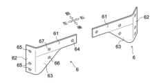
- Figure 5 is a perspective view of a pair of left and right brackets 6.
- the dashed lines in Figure 5 are lines illustrating the boundaries between the horizontal extensions 61 and the diagonal reinforcement parts 63.
- the brackets 6 are provided with a plurality of fixing parts (fastening holes) through which fasteners (bolts, rivets, studs, etc.) are inserted.
- the horizontal extensions 61 are provided with an inner fixing part 64 (inner joint part) and a second intermediate fixing part 67 (outer joint part)
- the diagonal reinforcement parts 63 are provided with an intermediate fixing part 66
- the vertical extensions 62 are provided with a plurality of outer fixing parts 65.
- the vertical extensions 62 are fixed to the strut outer 3 at a plurality of points spaced apart in the vertical direction.
- the inner fixing portion 64 and the second intermediate fixing portion 67 are spaced apart in the left-right direction (the vehicle width direction, the extension direction of the reinforcement 5), and the outer fixing portion 65 is spaced apart in the up-down direction.
- the second intermediate fixing portion 67 is a portion that connects the bracket 6 and the reinforcement 5 at a position near the outer end of the reinforcement 5 in the vehicle width direction relative to the reinforcement 5.
- the inner fixing portion 64 is a portion that connects the bracket 6 and the reinforcement 5 at a position spaced apart from the second intermediate fixing portion 67 in the extension direction of the reinforcement 5, and near the inner end of the lateral extension portion 61 in the vehicle width direction.
- the inner fixing part 64 is located at the innermost position in the vehicle width direction
- the outer fixing parts 65 are located at the outermost positions in the vehicle width direction.
- the outer fixing parts 65 are all located at the same position in the vehicle width direction.
- the intermediate fixing part 66 and the second intermediate fixing part 67 are provided at a position sandwiched horizontally between the inner fixing part 64 and the outer fixing part 65.
- the intermediate fixing part 66 and the second intermediate fixing part 67 may be located at the same position in the vehicle width direction, or one may be positioned shifted outward in the vehicle width direction relative to the other.
- the auxiliary bracket 7 is formed by bending a sheet metal cut into a predetermined shape. As shown in FIG. 4, the auxiliary bracket 7 has a side portion 71, a rear portion 72, and an upper portion 73.
- the side portion 71 is a flat portion that is joined to the inner surface portion 33 of the strut 1, and is fixed, for example, by welding and fastening in a state of surface contact with the inner surface portion 33.
- the fixing point between the side portion 71 and the inner surface portion 33 is set rearward and above the fixing point between the bracket 6 and the inclined surface portion 32, so that the auxiliary bracket 7 does not interfere with the bracket 6.
- the rear surface portion 72 is a planar portion perpendicular to the side surface portion 71, and is a vertical surface that is joined to the vertical surface portion 42.
- the rear surface portion 72 is welded and fixed, for example, in face-to-face contact with the vertical surface portion 42 (or the rear support portion 34 that is fixed integrally to the vertical surface portion 42).
- the top surface portion 73 is a planar portion perpendicular to the side surface portion 71 and the rear surface portion 72, and is a horizontal surface that is joined to the horizontal surface portion 41 (floor panel 15).
- the top surface portion 73 is welded and fixed, for example, in face-to-face contact with the floor panel 15.
- the floor panel 15, the top surface portion 73, and the horizontal surface portion 41 are welded and fixed in a partially triple-layered state.
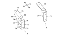
- FIG. 6 is a perspective view of a pair of left and right auxiliary brackets 7.
- Auxiliary bracket 7 is provided with a plurality of fixing portions (fastening holes) through which fasteners (bolts, rivets, studs, etc.) are inserted, and a plurality of fixing portions (welding points) which are fixed by welding.
- side portion 71 is provided with side fixing portion 74 and second side fixing portion 77.
- rear portion 72 is provided with rear fixing portion 75
- top portion 73 is provided with top fixing portion 76.
- side fixing portion 74, rear fixing portion 75, and top fixing portion 76 represent welding points
- second side fixing portion 77 represents a fastening hole.
- the side fixing parts 74 are arranged at multiple locations spaced apart at least in the vertical and front-rear directions. In the example shown in FIG. 6, there are four side fixing parts 74. Furthermore, multiple sets of side fixing parts 74 are arranged spaced apart in the front-rear direction, with two side fixing parts 74 spaced apart in the vertical direction and at the same position in the front-rear direction as one set. Furthermore, the second side fixing parts 77 are arranged at multiple locations spaced apart in the front-rear direction. In the example shown in FIG. 6, two second side fixing parts 77 are provided that are spaced apart in the front-rear direction and at the same position in the vertical direction. The vertical position of the second side fixing part 77 is preferably set to a position sandwiched between the upper side fixing part 74 and the lower side fixing part 74.
- the rear fixing parts 75 are arranged at multiple locations spaced apart in the vertical direction. In the example shown in FIG. 6, two rear fixing parts 75 are provided that are spaced apart in the vertical direction and at the same position in the left-right direction. Similarly, the top fixing parts 76 are arranged at multiple locations spaced apart in the front-rear direction. In the example shown in FIG. 6, two top fixing parts 76 are provided that are spaced apart in the front-rear direction and at the same position in the left-right direction. Of the two top fixing parts 76, one located on the front side fixes the floor panel 15 and the top part 73. The other located on the rear side fixes the floor panel 15, the top part 73, and the horizontal surface part 41 to each other.
- Figure 7 is a perspective view of the reinforcement 5 as viewed from below the floor panel 15 toward the rear of the vehicle.
- the dashed lines in Figure 7 indicate the connecting member 8.
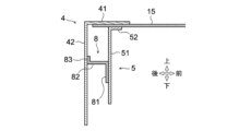
- Figure 8 is a cross-sectional view for explaining the structure of the connecting member 8.
- the connecting member 8 is formed by bending a cut plate that has been cut into a predetermined shape. As shown in Figures 7 and 8, the connecting member 8 has a connecting front portion 81, a connecting upper portion 82, and a connecting rear portion 83.
- the connecting front surface portion 81 is a planar portion that is joined to the reinforcing surface portion 51 of the reinforcement 5, and is fixed, for example, by welding in a state of partial surface contact with the reinforcing surface portion 51.
- the connecting upper surface portion 82 is a planar portion that extends from the upper end of the connecting front surface portion 81 toward the rear of the vehicle to a position that reaches the rear end panel 4.
- the longitudinal dimension of the connecting upper surface portion 82 corresponds to the distance (forward/rearward separation distance) between the rear end panel 4 and the reinforcement 5.
- the connecting rear surface portion 83 is a flat portion (edge-like portion) formed by bending the rear end portion of the connecting upper surface portion 82 upward, and is welded and fixed in a state of partial surface contact with the vertical surface portion 42 of the rear end panel 4, for example.
- the rear end portion of the floor panel 15 forms a reinforcing structure with a closed cross section surrounded by four sides: the vertical surface portion 42 of the rear end panel 4, the reinforcing surface portion 51 of the reinforcement 5, the connecting upper surface portion 82 of the connecting member 8, and the horizontal surface portion 41 of the rear end panel 4 (or the floor panel 15). This stabilizes the attachment state of the rear end panel 4 and the reinforcement 5, increases the rigidity near the rear end portion of the floor panel 15, and improves the robustness of the cargo box 11.
- the plate surfaces of the connecting front surface 81 and the connecting top surface 82 may be formed with a plurality of openings through which piping or wiring can be inserted, similar to the reinforcing surface 51 of the reinforcement 5.
- the connecting member 8 may be disposed in a position that does not interfere with the piping or wiring.
- a structure for increasing the rigidity of the connecting member 8 may also be applied to the connecting member 8.
- reinforcing structures such as ribs or beads may be provided on the plate surfaces and curved portions of each of the connecting front surface 81, the connecting top surface 82, and the connecting rear surface 83.
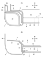
- Figure 9 (A) is a horizontal cross-sectional view of the strut 1 above the floor panel 15 with the rear gate 13 removed.
- the tail lamp unit 17 is disposed in a storage space surrounded by the outer panel 18 and the strut outer 3, and is attached to the outer panel 18 and the strut outer 3.
- the floor panel 15 on the inner side of the strut 1 in the vehicle width direction is reinforced by the rear end panel 4. Furthermore, the underside of the rear end panel 4 is reinforced by a reinforcement 5.
- Figure 9 (B) is a horizontal cross-sectional view of the strut 1 below the floor panel 15.
- the reinforcement 5 and the strut outer 3 are connected in the left-right direction by a bracket 6.
- the horizontal extension portion 61 of the bracket 6 is fixed to the arm portion 53 of the reinforcement 5, and the vertical extension portion 62 of the bracket 6 is fixed to the inclined surface portion 32 of the strut outer 3. This prevents the strut outer 3 from tipping over and deforming, improving the robustness of the cargo box structure.
- the vertical extension portion 62 of the bracket 6 is arranged to be inclined with respect to the horizontal extension portion 61 of the bracket 6.
- Auxiliary bracket 7 is provided behind bracket 6, connecting outer strut 3 and rear end panel 4.
- Side portion 71 of auxiliary bracket 7 is fixed to inner surface portion 33 of outer strut 3, and rear portion 72 of auxiliary bracket 7 is fixed to vertical surface portion 42 (rear support portion 34) of rear end panel 4.
- upper surface portion 73 of auxiliary bracket 7 is fixed to horizontal surface portion 41 of rear end panel 4 and floor panel 15. This more reliably suppresses deformation of outer strut 3 and rear end panel 4.
- the cargo box structure according to the present embodiment is provided in a vehicle 10 including a floor panel 15 of a cargo box 11, side gates 12 (side panels) erected on both outer sides of the floor panel 15 in the vehicle width direction, and columnar struts 1 provided on the side gates 12 and extending vertically relative to the floor panel 15, a planar reinforcement 5 suspended downward from the floor panel 15 and extending across the vehicle width direction, and a bracket 6 connecting the strut 1 and the reinforcement 5.
- the bracket 6 has a horizontal extension portion 61 and a vertical extension portion 62.
- the horizontal extension portion 61 extends in the extension direction of the reinforcement 5 and is connected to the reinforcement 5.
- the vertical extension portion 62 extends vertically further than the horizontal extension portion 61 and is connected to the strut 1.
- the distance (vertical distance) between the center of rotation during the lateral tilt rotation deformation of the side gate 12 and the fixed points of the strut 1 and bracket 6 can be secured. This makes it possible to efficiently prevent the side gate 12 from tipping over.
- the distance (vertical distance) between the center of rotation during the longitudinal flapping deformation of the reinforcement 5 and the fixed points of the strut 1 and bracket 6 can also be secured, making it possible to efficiently prevent the reinforcement 5 from flapping. Therefore, the rigidity of the side gate 12 and the floor panel 15 can be easily increased, and the robustness of the cargo box 11 can be improved with a simple configuration.
- the strut 1 has an inclined surface portion 32 that faces the vehicle front-rear direction and the inside of the vehicle width direction along the vertical direction.
- the bracket 6 is formed in a surface shape in which the vertical extension portion 62 is inclined forward and backward in accordance with the inclination of the inclined surface portion 32 with respect to the horizontal extension portion 61 as a reference. Furthermore, the vertical extension portion 62 is joined in a state where it is overlapped on the inclined surface portion 32. This makes it easy to apply a load acting on the fixing portion (fastener) between the vertical extension portion 62 and the strut 1 in the shear direction.
- the vertical extension portion 62 is formed into a surface shape parallel to the horizontal extension portion 61, a load in the peeling direction acts on the fixed point of the vertical extension portion 62 when the strut outer 3 or the reinforcement 5 rotates in the front-to-rear direction. Also, if the vertical extension portion 62 is formed into a surface shape perpendicular to the horizontal extension portion 61, a load in the peeling direction acts on the fixed point of the vertical extension portion 62 when the strut outer 3 rotates in the left-to-right direction. On the other hand, if the vertical extension portion 62 is inclined with respect to the horizontal extension portion 61, the load in the peeling direction as described above is less likely to be applied, and deformation of the strut 1 can be efficiently suppressed. Therefore, the robustness of the shipping box 11 can be further improved.
- the vertical extension portion 62 extends to the vicinity of the lower end of the strut 1 and is fixed to the strut 1 at multiple locations spaced apart in the vertical direction.
- the outer fixing portion 65 is disposed at multiple locations spaced apart in the vertical direction.
- the lateral extension portion 61 has a second intermediate fixing portion 67 (outer joint portion) and an inner fixing portion 64 (inner joint portion).
- the second intermediate fixing portion 67 is a portion that is joined to the reinforcement 5 at a position near the outer end of the reinforcement 5 in the vehicle width direction.
- the inner fixing portion 64 is a portion that is separated from the second intermediate fixing portion 67 in the extension direction (left-right direction) of the reinforcement 5, and is a portion that is joined to the reinforcement 5 at a position near the inner end of the lateral extension portion 61 in the vehicle width direction.
- the strut 1 is disposed at the rear end of the side gate 12.
- a rear end panel 4 having an L-shaped cross section and extending in the vehicle width direction is provided at the rear end of the cargo box 11.
- the rear end panel 4 has a horizontal surface portion 41 connected to the floor panel 15 and a vertical surface portion 42 extending downward from the rear end of the horizontal surface portion 41.
- the reinforcement 5 is located in front of the rear end panel 4 and is attached to the horizontal surface portion 41 or the floor panel 15, and is connected to the vertical surface portion 42 via a connecting member 8.
- the rigidity of the area near the rear end of the floor panel 15 can be increased, and the floor panel 15 can be effectively reinforced. Also, by reinforcing the rear end panel 4 with the reinforcement 5, deformation of the rear end panel 4 itself can be suppressed. Furthermore, by connecting the rear end panel 4 and the reinforcement 5 with the connecting member 8, the rigidity of the area near the rear end of the floor panel 15 can be further increased, and the robustness of the cargo box 11 can be improved.
- the above cargo box structure is provided with an auxiliary bracket 7 that connects the outer end of the rear end panel 4 in the vehicle width direction to the strut 1.
- the auxiliary bracket 7 has a rear surface portion 72 that is connected to the vertical surface portion 42, an upper surface portion 73 that is connected to the horizontal surface portion 41, and a side surface portion 71 that is connected to the inner surface portion 33 of the strut 1 that faces inward in the vehicle width direction.
- the structure of the left and right sides (struts 1) of the rear gate 13 is made robust, preventing deformation and malfunction of the rear gate 13.
- the rigidity of the auxiliary bracket 7 can be increased and the fixed state by the auxiliary bracket 7 can be stabilized. Therefore, the robustness of the cargo box 11 can be further improved with a simple configuration.
- the strut 1 is a portion that houses the tail lamp unit 17 of the vehicle 10 at the rear end of the side gate 12.
- the strut 1 has a strut outer 3 that forms a space for housing the tail lamp unit 17 between it and the outer panel 18 that forms the exterior of the side gate 12.
- the inclined surface portion 32 is formed between a front surface portion 31 of the strut 1 that faces forward of the vehicle and an inner surface portion 33 of the strut 1 that faces inward in the vehicle width direction, so as to connect the two in the vertical direction.
- the bracket 6 connects the strut outer 3 and the reinforcement 5 in the vehicle width direction.
- This configuration enhances the robustness of the area near the rear end of the side gate 12 and stabilizes the mounting state of the tail lamp unit 17, preventing failure of the tail lamp unit 17 due to vehicle body vibration, for example.
- the structure of the left and right sides (struts 1) of the rear gate 13 is made robust, preventing deformation and malfunction of the rear gate 13.
- the bracket 6 has a diagonal reinforcing portion 63 that diagonally connects the inside corner portion between the horizontal extension portion 61 and the vertical extension portion 62 when viewed from the front.
- the rigidity of the bracket 6 can be further increased and torsional deformation of the bracket 6 can be suppressed. Therefore, the robustness of the shipping box 11 can be further improved with a simple configuration.
- the bracket 6 is formed in a funnel shape that expands vertically from the horizontal extension portion 61 to the vertical extension portion 62 when viewed from the front.
- the diagonal reinforcement portion 63 is formed in a shape that fills the inside corner portion between the horizontal extension portion 61 and the vertical extension portion 62 without any gaps. This ensures a large joint area between the bracket 6 and the reinforcement 5, and further stabilizes the fixed state of the bracket 6.
- torsional deformation of the bracket 6 can be more reliably suppressed. Therefore, the robustness of the shipping box 11 can be further improved with a simple configuration.
- the strut 1 is provided at the corners of the left and right rear ends of the vehicle 10 (left and right sides of the rear gate 13), but the location of the strut 1 is not limited to this.
- the strut 1 may be located at the front end of the side gate 12, or in the middle between the front and rear ends of the side gate 12.
- the reinforcement 5 that reinforces the rear end panel 4 and the floor panel 15 is illustrated, but the rear end panel 4 is not a required element.
- the reinforcement 5 only needs to reinforce at least the floor panel 15, and only needs to be a planar member that extends downward from the floor panel 15.
- the extension direction of the reinforcement 5 does not have to be the left-right direction, but may be, for example, the front-rear direction.
- the bracket 6 has a horizontal extension portion 61, a vertical extension portion 62, and a diagonal reinforcement portion 63, but the diagonal reinforcement portion 63 can be omitted. Also, the auxiliary bracket 7 can be omitted.
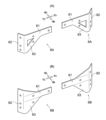
- FIG. 10(A) is a perspective view showing a modified bracket 6A.
- the diagonal reinforcement portion 63 of the bracket 6A is formed to connect the horizontal extension portion 61 and the vertical extension portion 62 while leaving a gap at the corner portion between the horizontal extension portion 61 and the vertical extension portion 62. This structure makes it possible to reduce the weight and cost while suppressing torsional deformation of the bracket 6.
- FIG. 10(B) is a perspective view showing a bracket 6B as another modified example.
- the vertical extension portion 62 of the bracket 6B is formed in a shape that extends upward and downward from the outer end of the horizontal extension portion 61 in the vehicle width direction.
- diagonal reinforcement portions 63 are provided on both the upper and lower sides of the horizontal extension portion 61.
- This invention can be used in the manufacturing industry of vehicles with cargo boxes, as well as in the manufacturing industry of cargo boxes and vehicle body structures around cargo boxes.
Landscapes
- Engineering & Computer Science (AREA)
- Chemical & Material Sciences (AREA)
- Combustion & Propulsion (AREA)
- Transportation (AREA)
- Mechanical Engineering (AREA)
- Body Structure For Vehicles (AREA)
Abstract
Description
態様4.上記の態様1~3の何れかにおいて、前記横延在部は、前記リンフォースに対し、前記リンフォースの車幅方向外側の端部近傍の位置で結合される外側結合部と、前記外側結合部から前記リンフォースの延設方向に離隔した前記横延在部の車幅方向内側の端部近傍の位置で結合される内側結合部と、を有することが好ましい。
態様9.上記の態様8において、前記ブラケットが、正面視において前記横延在部から前記縦延在部に向かって上下方向に広がる漏斗状に形成されることが好ましい。
図1は、実施例としての荷箱構造が適用された車両10の斜視図であり、図2は、車両10の左後端の角部を示す斜視図である。図1に示すように、この車両10には、乗員が搭乗する車室(キャビン)と荷箱11とが設けられる。荷箱11は、車室の後方に配置される。本実施例の車両10はラダーフレーム型の車台構造を備え、荷箱11が図示しないラダーフレームの上に搭載される。ラダーフレームとは、前後方向に延在する左右一対のサイドメンバーと、これらのサイドメンバーを左右方向に接続するクロスメンバーとを組み合わせて構成される梯子状のフレームである。
サイドゲート12は、荷箱11の左右側端部であってフロアパネル15の車幅方向両外側に立設される壁状の部位である。サイドゲート12は、例えば図2に示すように、その外装をなすアウターパネル18(サイドゲートアウターパネル)と、アウターパネル18に対して所定の間隔をあけて内側に配置されるインナーパネル19(サイドゲートインナーパネル)とを組み合わせて構成される。アウターパネル18及びインナーパネル19は、例えば互いの縁部が重ね合わされて溶接固定される。
フロントパネル14は、荷箱11の前端部に立設される壁状の部位である。フロントパネル14は省略してもよいし、荷箱11の前方に設けられる車室と一体に形成してもよい。フロアパネル15は、荷箱11の床面をなす平面状の部位である。フロアパネル15の板面には、例えば面剛性を高めるための凹凸形状やリブが形成される。また、フロアパネル15の下面側には、図示しない補強部材(クロスシル等)が取り付けられる。
本実施例の荷箱構造には、図2中に破線で示すブラケット6及び補助ブラケット7が設けられる。図3は、これらのブラケット6,7の構造を説明するために、フロアパネル15の下方から左側のストラット1の下部を見上げた状態を示す斜視図である。また、図4は、図3中に示される各種部材を分解して示す分解斜視図である。図3,図4では各種部材を接合するための手段(締結具等)の表示を省略している。
ストラットアウター3は、所定の形状に切断された切り板に折り曲げ加工を施すことで形成される。図4に示すように、ストラットアウター3には、前面部31,傾斜面部32,内面部33,後方支持部34,前方支持部35,第二前方支持部36が設けられる。
(1)本実施例に係る荷箱構造は、荷箱11のフロアパネル15と、フロアパネル15の車幅方向両外側で立設されるサイドゲート12(サイドパネル)と、サイドゲート12に設けられフロアパネル15に対して上下に延設される柱状のストラット1とを備える車両10において、フロアパネル15から下方へ垂設されて車幅方向に亘って延設される面状のリンフォース5と、ストラット1及びリンフォース5を接続するブラケット6とを備える。このブラケット6は、横延在部61と縦延在部62とを有する。横延在部61は、リンフォース5の延設方向に延在してリンフォース5に結合される。縦延在部62は、横延在部61よりも上下方向に延在してストラット1に結合される。
上記の実施例はあくまでも例示に過ぎず、本実施例で明示しない種々の変形や技術の適用を排除する意図はない。本実施例の各構成は、それらの趣旨を逸脱しない範囲で種々変形して実施できる。また、本実施例の各構成は必要に応じて取捨選択でき、あるいは、公知技術に含まれる各種構成と適宜組み合わせることができる。
2 ストラットインナー
3 ストラットアウター
4 リアエンドパネル
5 リンフォース
6,6A,6B ブラケット
7 補助ブラケット
8 連結部材
10 車両
11 荷箱
12 サイドゲート(サイドパネル)
13 リアゲート
14 フロントパネル
15 フロアパネル
16 リアバンパー
17 テールランプユニット
18 アウターパネル
19 インナーパネル
31 前面部
32 傾斜面部
33 内面部
34 後方支持部
35 前方支持部
36 第二前方支持部
41 水平面部
42 垂直面部
51 補強面部
52 縁部
53 腕部
61 横延在部
62 縦延在部
63 斜め補強部
64 内側固定部(内側結合部)
65 外側固定部
66 中間固定部
67 第二中間固定部(外側結合部)
71 側面部
72 後面部
73 上面部
74 側面固定部
75 後面固定部
76 上面固定部
77 第二側面固定部
81 連結前面部
82 連結上面部
83 連結後面部
Claims (9)
- 荷箱のフロアパネルと、前記フロアパネルの車幅方向両外側で立設されるサイドパネルと、前記サイドパネルに設けられ前記フロアパネルに対して上下に延設される柱状のストラットと、を備える車両の荷箱構造であって、
前記フロアパネルから下方へ垂設され、車幅方向に亘って延設される面状のリンフォースと、
前記ストラット及び前記リンフォースを接続するブラケットとを備え、
前記ブラケットが、前記リンフォースの延設方向に延在して前記リンフォースに結合される横延在部と、前記横延在部よりも上下方向に延在して前記ストラットに結合される縦延在部と、を有する
ことを特徴とする、車両の荷箱構造。 - 前記ストラットが、上下方向に沿って車両前後方向かつ車幅方向内側を向く傾斜面部を有し、
前記ブラケットが、前記横延在部を基準として前記縦延在部を前記傾斜面部の傾斜に合わせて前後に傾斜させた面形状に形成され、
前記縦延在部が、前記傾斜面部に重ねられた状態で結合される
ことを特徴とする、請求項1記載の車両の荷箱構造。 - 前記縦延在部が、前記ストラットの下端部近傍まで延設され、前記ストラットに対し、上下方向に離隔した複数箇所に固定される
ことを特徴とする、請求項1又は2記載の車両の荷箱構造。 - 前記横延在部は、前記リンフォースに対し前記リンフォースの車幅方向外側の端部近傍の位置で結合される外側結合部と、前記外側結合部から前記リンフォースの延設方向に離隔した前記横延在部の車幅方向内側の端部近傍の位置で結合される内側結合部と、を有する
ことを特徴とする、請求項1~3の何れか一項に記載の車両の荷箱構造。 - 前記ストラットが、前記サイドパネルの後端部に配置され、
前記荷箱の後端部には、前記フロアパネルに連結される水平面部と当該水平面部の後端から下方に向かって延設される垂直面部とを有する断面L字状に形成されて車幅方向に延在するリアエンドパネルが設けられ、
前記リンフォースが、前記リアエンドパネルの前方に位置して、前記水平面部又は前記フロアパネルに取り付けられるとともに前記垂直面部と連結部材を介して連結されている
ことを特徴とする、請求項1~4の何れか一項に記載の車両の荷箱構造。 - 前記リアエンドパネルの車幅方向外側の端部と前記ストラットとを接続する補助ブラケットをさらに備え、
前記補助ブラケットは、前記垂直面部に結合される後面部と、前記水平面部に結合される上面部と、前記ストラットの車幅方向内側を向く内面部に結合される側面部と、を有する
ことを特徴とする、請求項5記載の車両の荷箱構造。 - 前記ストラットが、前記サイドパネルの後端部において前記車両のテールランプユニットを収容する部位であって、前記サイドパネルの外装をなすアウターパネルとの間に前記テールランプユニットの収容空間を形成するストラットアウターを有し、
前記ストラットアウターが、前記ストラットの車両前方を向く前面部と、前記ストラットの車幅方向内側を向く内面部と、上下方向に沿って車両前後方向かつ車幅方向内側を向き前記前面部及び前記内面部を繋ぐように形成される傾斜面部と、を有し、
前記ブラケットが、前記ストラットアウターと前記リンフォースとを車幅方向に接続する
ことを特徴とする、請求項5又は6記載の車両の荷箱構造。 - 前記ブラケットが、正面視において前記横延在部と前記縦延在部との入隅部分を斜めに接続する斜め補強部を有する
ことを特徴とする、請求項1~7の何れか一項に記載の車両の荷箱構造。 - 前記ブラケットが、正面視において前記横延在部から前記縦延在部に向かって上下方向に広がる漏斗状に形成される
ことを特徴とする、請求項8記載の車両の荷箱構造。
Priority Applications (2)
| Application Number | Priority Date | Filing Date | Title |
|---|---|---|---|
| PCT/JP2023/012986 WO2024201847A1 (ja) | 2023-03-29 | 2023-03-29 | 車両の荷箱構造 |
| JP2025509458A JPWO2024201847A1 (ja) | 2023-03-29 | 2023-03-29 |
Applications Claiming Priority (1)
| Application Number | Priority Date | Filing Date | Title |
|---|---|---|---|
| PCT/JP2023/012986 WO2024201847A1 (ja) | 2023-03-29 | 2023-03-29 | 車両の荷箱構造 |
Publications (1)
| Publication Number | Publication Date |
|---|---|
| WO2024201847A1 true WO2024201847A1 (ja) | 2024-10-03 |
Family
ID=92903665
Family Applications (1)
| Application Number | Title | Priority Date | Filing Date |
|---|---|---|---|
| PCT/JP2023/012986 Ceased WO2024201847A1 (ja) | 2023-03-29 | 2023-03-29 | 車両の荷箱構造 |
Country Status (2)
| Country | Link |
|---|---|
| JP (1) | JPWO2024201847A1 (ja) |
| WO (1) | WO2024201847A1 (ja) |
Citations (4)
| Publication number | Priority date | Publication date | Assignee | Title |
|---|---|---|---|---|
| US20200079441A1 (en) * | 2017-05-17 | 2020-03-12 | Aluminum Industries Investments Pty Ltd | Utility vehicle corner module with gate securing apparatus |
| EP3712040A1 (en) * | 2019-03-21 | 2020-09-23 | Adela, Danuta Koziolek | Trailer plattform |
| JP2022064095A (ja) * | 2020-10-13 | 2022-04-25 | 日産自動車株式会社 | トラックの車体 |
| US20220379977A1 (en) * | 2021-05-28 | 2022-12-01 | Nissan North America, Inc. | Vehicle cargo structure |
-
2023
- 2023-03-29 JP JP2025509458A patent/JPWO2024201847A1/ja active Pending
- 2023-03-29 WO PCT/JP2023/012986 patent/WO2024201847A1/ja not_active Ceased
Patent Citations (4)
| Publication number | Priority date | Publication date | Assignee | Title |
|---|---|---|---|---|
| US20200079441A1 (en) * | 2017-05-17 | 2020-03-12 | Aluminum Industries Investments Pty Ltd | Utility vehicle corner module with gate securing apparatus |
| EP3712040A1 (en) * | 2019-03-21 | 2020-09-23 | Adela, Danuta Koziolek | Trailer plattform |
| JP2022064095A (ja) * | 2020-10-13 | 2022-04-25 | 日産自動車株式会社 | トラックの車体 |
| US20220379977A1 (en) * | 2021-05-28 | 2022-12-01 | Nissan North America, Inc. | Vehicle cargo structure |
Also Published As
| Publication number | Publication date |
|---|---|
| JPWO2024201847A1 (ja) | 2024-10-03 |
Similar Documents
| Publication | Publication Date | Title |
|---|---|---|
| EP1129929B1 (en) | Automotive floor structure | |
| JP4654917B2 (ja) | 車体後部構造 | |
| JP2014061809A (ja) | 車両後部構造 | |
| JP6600873B2 (ja) | 車体構造 | |
| JP5493971B2 (ja) | 車両の後部車体構造 | |
| CN100390007C (zh) | 车辆的后部车体结构 | |
| WO2016129065A1 (ja) | 車体後部構造 | |
| JP6977578B2 (ja) | 車両の後部車体構造 | |
| JP7106974B2 (ja) | 車両の側部車体構造 | |
| JP5708428B2 (ja) | 車両用バックドア構造 | |
| JP6176227B2 (ja) | 車両の前部車体構造 | |
| JP7600603B2 (ja) | トラックの車体 | |
| JP3739976B2 (ja) | 自動車の車体構造 | |
| JP4690961B2 (ja) | 車両の後部ドア構造 | |
| WO2024201847A1 (ja) | 車両の荷箱構造 | |
| JPH06144299A (ja) | 自動車の下部車体構造 | |
| JP4696664B2 (ja) | 車両の後部車体構造 | |
| JP6977652B2 (ja) | 車両の前部車体構造 | |
| JP6973104B2 (ja) | 車両の後部車体構造 | |
| JP4616015B2 (ja) | 三角窓補強構造 | |
| JP4984679B2 (ja) | 分割可倒式シートバックのセンターヒンジ構造 | |
| JP7348601B1 (ja) | 車両の後部構造 | |
| JP6977579B2 (ja) | 車両の後部車体構造 | |
| JP3274079B2 (ja) | 横開き式バックドアの支持構造 | |
| JP5969246B2 (ja) | 車体前部構造 |
Legal Events
| Date | Code | Title | Description |
|---|---|---|---|
| 121 | Ep: the epo has been informed by wipo that ep was designated in this application |
Ref document number: 23930485 Country of ref document: EP Kind code of ref document: A1 |
|
| ENP | Entry into the national phase |
Ref document number: 2025509458 Country of ref document: JP Kind code of ref document: A |
|
| WWE | Wipo information: entry into national phase |
Ref document number: 2025509458 Country of ref document: JP |
|
| NENP | Non-entry into the national phase |
Ref country code: DE |
|
| 122 | Ep: pct application non-entry in european phase |
Ref document number: 23930485 Country of ref document: EP Kind code of ref document: A1 |