WO2024185121A1 - 固定子および固定子の製造方法 - Google Patents
固定子および固定子の製造方法 Download PDFInfo
- Publication number
- WO2024185121A1 WO2024185121A1 PCT/JP2023/009012 JP2023009012W WO2024185121A1 WO 2024185121 A1 WO2024185121 A1 WO 2024185121A1 JP 2023009012 W JP2023009012 W JP 2023009012W WO 2024185121 A1 WO2024185121 A1 WO 2024185121A1
- Authority
- WO
- WIPO (PCT)
- Prior art keywords
- cylindrical member
- stator
- core
- end portion
- elastic member
- Prior art date
- Legal status (The legal status is an assumption and is not a legal conclusion. Google has not performed a legal analysis and makes no representation as to the accuracy of the status listed.)
- Ceased
Links
Images




Classifications
-
- H—ELECTRICITY
- H02—GENERATION; CONVERSION OR DISTRIBUTION OF ELECTRIC POWER
- H02K—DYNAMO-ELECTRIC MACHINES
- H02K15/00—Processes or apparatus specially adapted for manufacturing, assembling, maintaining or repairing of dynamo-electric machines
- H02K15/12—Impregnating, moulding insulation, heating or drying of windings, stators, rotors or machines
- H02K15/122—Impregnating, moulding insulation, heating or drying of windings, stators, rotors or machines of windings
-
- H—ELECTRICITY
- H02—GENERATION; CONVERSION OR DISTRIBUTION OF ELECTRIC POWER
- H02K—DYNAMO-ELECTRIC MACHINES
- H02K15/00—Processes or apparatus specially adapted for manufacturing, assembling, maintaining or repairing of dynamo-electric machines
- H02K15/12—Impregnating, moulding insulation, heating or drying of windings, stators, rotors or machines
- H02K15/121—Impregnating, moulding insulation, heating or drying of windings, stators, rotors or machines of cores
Definitions
- This disclosure relates to a stator and a method for manufacturing a stator.
- motors that have a stator with a coil and a rotor that is rotatably arranged inside the stator.
- a molded resin may be filled into the inner space of a cylindrical member that covers the coil end portion of the coil (for example, JP 2004-120923 A).
- the cylindrical member may be processed after the molding resin is filled into the inner space of the cylindrical member. In this case, it is desirable to prevent dimensional defects in the processed cylindrical member.
- the first aspect of the present disclosure is a stator having a core, a coil provided on the core and having a coil end portion protruding from the axial end of the core, a cylindrical member that contacts the end of the core and covers the outer periphery of the coil end portion, and a molded resin that fills the inner space of the cylindrical member, and is provided with an elastic member that is disposed between the cylindrical member and the molded resin and that is in close contact with each of the cylindrical member and the molded resin.
- the second aspect of the present disclosure is a method for manufacturing a stator, including a filling step of filling the inner space of a cylindrical member attached to each of both axial ends of a core with molten resin, a cooling step of cooling the molten resin to harden the molten resin, and a cutting step of cutting the outer circumferential surface of the cylindrical member until the step between the outer circumferential surface of the cylindrical member and the outer circumferential surface of the core is equal to or less than an allowable value, and each of the cylindrical members before being filled with the molten resin in the filling step is in contact with the end of the core in the axial direction and covers the outer periphery of the coil end portion protruding from the end, and an elastic member is bonded to the inner surface of each of the cylindrical members, and the cutting in the cutting step is performed in a state in which the elastic member bonded to the inner surface of the cylindrical member is in close contact with the molded resin obtained by hardening the molten resin.
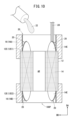
- FIG. 1 is a cross-sectional view of a stator of a motor according to an embodiment.
- FIG. 2 is a flow chart showing the procedure of the manufacturing process of the stator.
- FIG. 3 is a cross-sectional view showing the state after the mounting process.
- FIG. 4 is a diagram showing a cylindrical member that is attached in the attachment process.
- FIG. 5 is a cross-sectional view showing the state after the filling step.
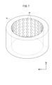
- FIG. 6 is a diagram showing a cylindrical member according to the first modification.
- FIG. 7 is a diagram showing a cylindrical member according to the second modification.
- FIG. 8 is a diagram showing a cylindrical member according to the third modification.
- FIG. 9 is a cross-sectional view of a stator of a motor according to the fifth modification.
- FIG. 10 is a cross-sectional view showing a state after the mounting step in the fifth modified example.
- the molded resin that fills the inner space of the cylindrical member that covers the coil end portion of the coil is in a molten state when filling the inner space, and hardens after filling the inner space.
- the molded resin may shrink when it transitions from a molten state to a hardened state.
- the gap causes dimensional defects in the processed cylindrical member.
- the following disclosure is an embodiment for suppressing the occurrence of dimensional defects in the processed cylindrical member.
- FIG. 1 is a cross-sectional view of a stator 10 of a motor according to an embodiment.
- the stator 10 includes a core 12, a coil 14, a cylindrical member 16, a molded resin 18, and an elastic member 20.
- the core 12 is composed of, for example, multiple magnetic steel plates 12a stacked in the axial direction DA.
- the axial direction DA is the direction in which the axis AX of the core 12 extends.
- the axis AX of the core 12 coincides with the rotation axis of the stator 10.
- the core 12 is also called an iron core.
- the core 12 has a cylindrical core body and multiple teeth that protrude from the core body inward in the radial direction DB of the core 12.
- a coil 14 is provided on each tooth. The coil 14 may be wound around the teeth.
- the coil 14 has a coil end portion 14E.
- the coil end portion 14E protrudes from one end 12E1 of the core 12 and the other end 12E2 of the core 12.
- the one end 12E1 and the other end 12E2 of the core 12 are each the ends 12E in the axial direction DA of the core 12.
- a power line LN is connected to the coil 14.
- the cylindrical member 16 is a member formed into a cylindrical shape.
- the cylindrical member 16 is formed from, for example, aluminum or an iron-based material.
- the cylindrical member 16 is disposed at the end 12E of the core 12 in the axial direction DA.
- the cylindrical member 16 disposed at one end 12E1 of the core 12 may be referred to as the cylindrical member 16A.
- the cylindrical member 16 disposed at the other end 12E2 of the core 12 may be referred to as the cylindrical member 16B.
- the cylindrical members 16A and 16B have substantially the same configuration.
- the cylindrical member 16 contacts the end 12E of the core 12 in the axial direction DA.
- the cylindrical member 16 surrounds the coil end portion 14E from the outside and covers the outer periphery of the coil end portion 14E.
- the molded resin 18 is placed inside the cylindrical member 16.
- the molded resin 18 fills the inner space of the cylindrical member 16. After filling, the molded resin 18 transitions from a molten state to a hardened state.
- the elastic member 20 is disposed between the cylindrical member 16 and the molded resin 18.
- the elastic member 20 has a ring shape.
- the elastic member 20 is disposed around the entire circumferential direction of the inner surface of the cylindrical member 16 at the end of the cylindrical member 16 opposite the core 12 side.
- the elastic member 20 is preferably made of an insulating material to ensure insulation between the coil 14 and the cylindrical member 16.
- the elastic member 20 is in close contact with both the cylindrical member 16 and the molded resin 18.
- the elastic member 20 has adhesive layers 20LY on both sides.
- the adhesive layer 20LY on one side of the elastic member 20 adheres to the inner surface of the cylindrical member 16, and the adhesive layer 20LY on the other side adheres to the molded resin 18.
- the elastic member 20 may be a double-sided tape or an adhesive.
- the adhesive layer 20LY may also be an adhesive.
- the elastic member 20 is disposed around the entire circumference of the cylindrical member 16. Therefore, the elastic member 20 can be firmly maintained in contact with both the cylindrical member 16 and the molded resin 18.
- the method for manufacturing the stator 10 includes an attachment process P1, a filling process P2, a cooling process P3, and a cutting process P4 (see Figure 2).
- the mounting process P1 is a process of mounting the cylindrical member 16 to the core 12 (see FIG. 3).
- the cylindrical member 16A is fixed to one end 12E1 of the core 12, for example, by shrink fitting.
- the cylindrical member 16A covers the outer periphery of the coil end portion 14E protruding from one end 12E1 of the core 12.
- the cylindrical member 16B is fixed to the other end 12E2 of the core 12, for example, by shrink fitting. In this case, the cylindrical member 16B covers the outer periphery of the coil end portion 14E protruding from the other end 12E2 of the core 12.
- An elastic member 20 is bonded to the inner peripheral surface of the cylindrical member 16 attached to the core 12 (see FIG. 4).
- the elastic member 20 may be bonded before the cylindrical member 16 is fixed to the core 12, or may be bonded after the cylindrical member 16 is fixed to the core 12.
- the filling process P2 is a process of filling the inner space of the cylindrical member 16 attached to the core 12 with molten resin 22 (see FIG. 3).
- the molten resin 22 is obtained by heating and liquefying the molded resin 18. Examples of such resins include thermoplastic resins.
- the molten resin 22 is poured into the inner space of the cylindrical member 16, for example, from the cylindrical member 16A. In this case, the space AR formed in the core 12 to position the rotor (not shown) and the opening 18OP of the cylindrical member 16B are blocked.
- the molten resin 22 poured from the cylindrical member 16A flows between the teeth of the core 12 into the inner space of the cylindrical member 16B and is stored there.
- the molten resin 22 fills the inner spaces of the cylindrical members 16A and 16B (see FIG. 5)
- the coil end portion 14E and the connection portion between the coil end portion 14E and the power line LN are immersed in the molten resin 22.
- the cooling process P3 is a process for cooling and hardening the molten resin 22.
- the process waits until the molten resin 22 hardens.
- the molten resin 22 hardens and transitions into the molded resin 18.
- the molded resin 18 and the elastic member 20 are bonded together. Therefore, even if the molded resin 18 shrinks during the hardening process, the elastic member 20 follows the shrinkage and maintains the close contact between the molded resin 18 and the cylindrical member 16. This prevents the molded resin 18 and the cylindrical member 16 from separating, resulting in the formation of a gap between the molded resin 18 and the cylindrical member 16.
- the cutting process P4 is a process for machining the cylindrical member 16.
- the outer circumferential surface of the cylindrical member 16 is cut until the step ST (see FIG. 5) between the outer circumferential surface of the cylindrical member 16 and the outer circumferential surface of the core 12 is equal to or less than the allowable value.
- cutting is performed until the step ST becomes zero.
- a lathe is used.
- the stator 10 is obtained (see FIG. 1). In this case, the outer circumferential surface of the cylindrical member 16 and the outer circumferential surface of the core 12 are roughly flush with each other.
- the elastic member 20 maintains the close contact between the molded resin 18 and the cylindrical member 16. Therefore, the cutting process for the cylindrical member 16 can be stabilized compared to a case where a gap occurs between the molded resin 18 and the cylindrical member 16 due to shrinkage of the molded resin 18. As a result, it is possible to prevent dimensional defects in the cylindrical member 16 and reduced yields.
- (Variation 1) 6 is a diagram showing a cylindrical member 16 of Modification 1.
- a plurality of elastic members 20 are bonded to the inner peripheral surface of the cylindrical member 16 that is attached to the core 12 in the attachment step P1.
- the multiple elastic members 20 are arranged at intervals in the axial direction DA of the cylindrical member 16.
- Each elastic member 20 has a ring shape.
- Each elastic member 20 is arranged around the entire circumferential direction of the inner circumferential surface of the cylindrical member 16.
- the contact area of the elastic member 20 with both the cylindrical member 16 and the molded resin 18 is increased compared to the embodiment. Therefore, the elastic member 20 can be firmly maintained in contact with both the cylindrical member 16 and the molded resin 18.
- (Variation 2) 7 is a diagram showing a cylindrical member 16 of Modification 2.
- a plurality of elastic members 20 are bonded to the inner peripheral surface of the cylindrical member 16 that is attached to the core 12 in the attachment step P1.
- the multiple elastic members 20 are arranged at intervals in both the axial direction DA of the cylindrical member 16 and the circumferential direction of the cylindrical member 16.
- Each elastic member 20 has a hemispherical outer shape.
- the surface of each elastic member 20 that comes into contact with the inner peripheral surface of the cylindrical member 16 is formed into a flat surface.
- the contact area (first contact area) of the elastic member 20 with the cylindrical member 16 can be made small, while the contact area (second contact area) of the elastic member 20 with the molded resin 18 can be made larger than the first contact area.
- the adhesion with the molded resin 18 that hardens from a molten state can be improved.
- the concentration of stress generated in the elastic member 20 due to the contraction of the molded resin 18 can be reduced.
- (Variation 3) 8 is a diagram showing a cylindrical member 16 of Modification 3.
- a plurality of elastic members 20 are adhered to the inner peripheral surface of the cylindrical member 16 that is attached to the core 12 in the attachment step P1.
- the multiple elastic members 20 are arranged at intervals in the circumferential direction of the cylindrical member 16. Each elastic member 20 extends along the axial direction DA of the cylindrical member 16. Each elastic member 20 has multiple polygonal portions 20A with a polygonal outer shape. The multiple polygonal portions 20A are connected along the axial direction DA of the cylindrical member 16. Compared to a case where no polygonal portions 20A are formed and the elastic member 20 extends straight along the axial direction DA of the cylindrical member 16, the contact area of the elastic member 20 with the molded resin 18 is increased. As a result, the adhesion with the molded resin 18 that hardens from a molten state can be improved.
- a through hole TH is formed in each polygonal portion 20A.
- One through hole TH is provided for each polygonal portion 20A.
- each polygonal portion 20A has a ring shape. Compared to a case where no through hole TH is formed in the elastic member 20, the contact area between the elastic member 20 and the molded resin 18 is increased. As a result, the adhesion with the molded resin 18 that hardens from a molten state can be improved.
- the elastic member 20 may be bonded to the entire inner circumferential surface of the cylindrical member 16 that is attached to the core 12 in the attachment step P1.
- (Variation 5) 9 is a cross-sectional view of the stator 10 of the motor of the modified example 5.
- the elastic member 20 may be disposed between the surface of the coil end portion 14E and the molded resin 18, in addition to being disposed between the cylindrical member 16 and the molded resin 18.
- the elastic member 20 is also in close contact with both the coil end portion 14E and the molded resin 18. As a result, the cutting process for the cylindrical member 16 can be made even more stable.
- the elastic member 20 is adhered to the inner circumferential surface of the cylindrical member 16 and the surface of the coil end portion 14E.
- the elastic member 20 may be adhered before the cylindrical member 16 is fixed to the core 12, or may be adhered after the cylindrical member 16 is fixed to the core 12.
- the elastic member 20 may be provided after the cooling step P3. In this case, the elastic member 20 is not bonded to the inner peripheral surface of the cylindrical member 16 in the mounting step P1.
- a liquid adhesive is filled in the gap between the cylindrical member 16 and the molded resin 18 obtained by hardening the molten resin 22 in the cooling step P3.
- the cutting step P4 is performed. That is, the cutting of the cylindrical member 16 is performed in a state in which the cylindrical member 16 and the molded resin 18 are bonded by the adhesive.
- the adhesive may also be filled in the gap between the surface of the coil end portion 14E and the molded resin 18.
- the elastic member 20 maintains close contact between the molded resin 18 and the cylindrical member 16.
- the elastic member 20 may maintain close contact between the molded resin 18 and the coil end portion 14E. This can suppress the occurrence of dimensional defects in the cylindrical member 16.
- the present disclosure relates to a stator (10) having a core (12), a coil (14) provided on the core and having a coil end portion (14E) protruding from an end (12E) in an axial direction (DA) of the core, a cylindrical member (16) in contact with the end of the core and covering the outer periphery of the coil end portion, and molded resin (18) filled into the inner space of the cylindrical member, and further comprising an elastic member (20) disposed between the cylindrical member and the molded resin and in close contact with each of the cylindrical member and the molded resin.
- the elastic member may have an adhesive layer (20LY) on a surface facing the molding resin and a surface facing the cylindrical member.
- the elastic member may be disposed over an entire circumferential circumference of the cylindrical member.
- the elastic member may be disposed between at least a portion of a surface of the coil end portion and the molded resin, and may be in close contact with both the coil end portion and the molded resin.
- the elastic members may be arranged at intervals in the axial direction.
- a method for manufacturing a stator includes a filling step of filling molten resin (22) into an inner space of a cylindrical member attached to each of both axial ends of a core, a cooling step of cooling the molten resin to harden the molten resin, and a cutting step of cutting the outer circumferential surface of the cylindrical member until a step between an outer circumferential surface of the cylindrical member and an outer circumferential surface of the core becomes equal to or less than an allowable value, wherein each of the cylindrical members before being filled with the molten resin in the filling step contacts an end of the core in the axial direction and covers an outer periphery of a coil end portion protruding from the end, and an elastic member is bonded to the inner surface of each of the cylindrical members, and the cutting in the cutting step is performed in a state where the elastic member bonded to the inner surface of the cylindrical member is in close contact with molded resin obtained by hardening of the molten resin.
- the elastic member before being filled with the molten resin in the filling step may also be adhered to a surface of the coil end portion, and the cutting in the cutting step may be performed in a state in which the elastic member adhered to the inner surface of the cylindrical member and the surface of the coil end portion is in close contact with the molded resin.
- the elastic member may have an adhesive layer on a surface facing the molded resin, and the cutting in the cutting step may be performed in a state in which the elastic member is also adhered to the molded resin.
- a method for manufacturing a stator includes the steps of: filling, with molten resin, the inner space of cylindrical members attached to both axial ends of a core; a cooling step for cooling the molten resin to harden it; and a cutting step for cutting the outer circumferential surface of the cylindrical members, wherein, after the cooling step, adhesive is filled into the gap between each of the cylindrical members that contact the axial ends of the core and cover the outer peripheries of the coil end portions protruding from the ends, and molded resin obtained by hardening of the molten resin, and the cutting step is performed in a state in which the cylindrical members and the molded resin are bonded together by the adhesive.
- the adhesive may also be filled into a gap between at least a portion of a surface of the coil end portion and the molding resin, and the cutting step may be performed in a state in which the cylindrical member and each of the coil end portions are adhered to the molding resin.
- stator 12 core 14 coil 14E coil end portion 16 cylindrical member 18 molded resin 20 elastic member 22 molten resin
Landscapes
- Engineering & Computer Science (AREA)
- Manufacturing & Machinery (AREA)
- Power Engineering (AREA)
- Manufacture Of Motors, Generators (AREA)
- Insulation, Fastening Of Motor, Generator Windings (AREA)
Priority Applications (5)
| Application Number | Priority Date | Filing Date | Title |
|---|---|---|---|
| JP2025505026A JPWO2024185121A1 (https=) | 2023-03-09 | 2023-03-09 | |
| PCT/JP2023/009012 WO2024185121A1 (ja) | 2023-03-09 | 2023-03-09 | 固定子および固定子の製造方法 |
| CN202380095213.4A CN120814146A (zh) | 2023-03-09 | 2023-03-09 | 定子以及定子的制造方法 |
| DE112023005497.5T DE112023005497T5 (de) | 2023-03-09 | 2023-03-09 | Stator und verfahren zur herstellung eines stators |
| TW113108252A TW202437647A (zh) | 2023-03-09 | 2024-03-07 | 定子及定子之製造方法 |
Applications Claiming Priority (1)
| Application Number | Priority Date | Filing Date | Title |
|---|---|---|---|
| PCT/JP2023/009012 WO2024185121A1 (ja) | 2023-03-09 | 2023-03-09 | 固定子および固定子の製造方法 |
Publications (1)
| Publication Number | Publication Date |
|---|---|
| WO2024185121A1 true WO2024185121A1 (ja) | 2024-09-12 |
Family
ID=92674497
Family Applications (1)
| Application Number | Title | Priority Date | Filing Date |
|---|---|---|---|
| PCT/JP2023/009012 Ceased WO2024185121A1 (ja) | 2023-03-09 | 2023-03-09 | 固定子および固定子の製造方法 |
Country Status (5)
| Country | Link |
|---|---|
| JP (1) | JPWO2024185121A1 (https=) |
| CN (1) | CN120814146A (https=) |
| DE (1) | DE112023005497T5 (https=) |
| TW (1) | TW202437647A (https=) |
| WO (1) | WO2024185121A1 (https=) |
Citations (3)
| Publication number | Priority date | Publication date | Assignee | Title |
|---|---|---|---|---|
| JP2010068699A (ja) * | 2008-09-12 | 2010-03-25 | Fanuc Ltd | 固定子鉄心およびエンドカバーを結合する嵌合部を具備する電動機 |
| JP2012120261A (ja) * | 2010-11-29 | 2012-06-21 | Mitsubishi Electric Corp | モールド成型治具、モールド成型方法及びステータ |
| JP2020205734A (ja) * | 2019-06-19 | 2020-12-24 | Nok株式会社 | モータのステータ構造およびモータ |
-
2023
- 2023-03-09 JP JP2025505026A patent/JPWO2024185121A1/ja active Pending
- 2023-03-09 WO PCT/JP2023/009012 patent/WO2024185121A1/ja not_active Ceased
- 2023-03-09 DE DE112023005497.5T patent/DE112023005497T5/de active Pending
- 2023-03-09 CN CN202380095213.4A patent/CN120814146A/zh active Pending
-
2024
- 2024-03-07 TW TW113108252A patent/TW202437647A/zh unknown
Patent Citations (3)
| Publication number | Priority date | Publication date | Assignee | Title |
|---|---|---|---|---|
| JP2010068699A (ja) * | 2008-09-12 | 2010-03-25 | Fanuc Ltd | 固定子鉄心およびエンドカバーを結合する嵌合部を具備する電動機 |
| JP2012120261A (ja) * | 2010-11-29 | 2012-06-21 | Mitsubishi Electric Corp | モールド成型治具、モールド成型方法及びステータ |
| JP2020205734A (ja) * | 2019-06-19 | 2020-12-24 | Nok株式会社 | モータのステータ構造およびモータ |
Also Published As
| Publication number | Publication date |
|---|---|
| CN120814146A (zh) | 2025-10-17 |
| DE112023005497T5 (de) | 2025-12-04 |
| JPWO2024185121A1 (https=) | 2024-09-12 |
| TW202437647A (zh) | 2024-09-16 |
Similar Documents
| Publication | Publication Date | Title |
|---|---|---|
| KR100327693B1 (ko) | 전동기의 로터 | |
| JP2539053B2 (ja) | 回転電機の製造方法 | |
| JP5363255B2 (ja) | ステータの製造方法、およびステータ | |
| US6787950B2 (en) | Stator for an electric drive with a tubular insulator as lost casting mold | |
| TWI727223B (zh) | 軸向間隙型旋轉電機 | |
| WO2016185829A1 (ja) | 回転子、回転電機および回転子の製造方法 | |
| JPH0919091A (ja) | 同期電動機のロータ | |
| JP6937811B2 (ja) | 回転電機および回転電機の製造方法 | |
| WO2018138858A1 (ja) | アキシャルギャップ型回転電機及びその製造方法 | |
| JP2004112856A (ja) | 回転電機の冷却構造及びその製造方法 | |
| CN116613910A (zh) | 马达及其制造方法 | |
| KR101728543B1 (ko) | 모터의 회전자 | |
| JPWO2018025407A1 (ja) | コンシクエントポール型の回転子、電動機および空気調和機 | |
| WO2024185121A1 (ja) | 固定子および固定子の製造方法 | |
| JP2025168451A (ja) | 固定子、回転電機、固定子の製造方法、および、回転電機の製造方法 | |
| JP5954693B2 (ja) | インシュレータ及び回転電機 | |
| JP2014187856A (ja) | ステータコアの絶縁構造及びステータの組付方法 | |
| EP2448091B1 (en) | Stator for electric motor, electric motor, and electric bicycle | |
| JP3639130B2 (ja) | モールド電動機およびその製造方法 | |
| JPWO2011114758A1 (ja) | ステータおよび回転電機 | |
| JP3398977B2 (ja) | 永久磁石界磁ロータ | |
| JP5286121B2 (ja) | トロイダル巻線モータ | |
| JP7436266B2 (ja) | 固定子及び電動機 | |
| WO2024247118A1 (ja) | ロータ | |
| JP6320653B1 (ja) | 電動機の固定子の製造方法、電動機の固定子及び電動機 |
Legal Events
| Date | Code | Title | Description |
|---|---|---|---|
| 121 | Ep: the epo has been informed by wipo that ep was designated in this application |
Ref document number: 23926331 Country of ref document: EP Kind code of ref document: A1 |
|
| ENP | Entry into the national phase |
Ref document number: 2025505026 Country of ref document: JP Kind code of ref document: A |
|
| WWE | Wipo information: entry into national phase |
Ref document number: 2025505026 Country of ref document: JP |
|
| WWE | Wipo information: entry into national phase |
Ref document number: 112023005497 Country of ref document: DE Ref document number: 202380095213.4 Country of ref document: CN |
|
| WWP | Wipo information: published in national office |
Ref document number: 202380095213.4 Country of ref document: CN |
|
| WWP | Wipo information: published in national office |
Ref document number: 112023005497 Country of ref document: DE |
|
| 122 | Ep: pct application non-entry in european phase |
Ref document number: 23926331 Country of ref document: EP Kind code of ref document: A1 |