WO2024166890A1 - カテーテルおよびカテーテルシステム - Google Patents
カテーテルおよびカテーテルシステム Download PDFInfo
- Publication number
- WO2024166890A1 WO2024166890A1 PCT/JP2024/003803 JP2024003803W WO2024166890A1 WO 2024166890 A1 WO2024166890 A1 WO 2024166890A1 JP 2024003803 W JP2024003803 W JP 2024003803W WO 2024166890 A1 WO2024166890 A1 WO 2024166890A1
- Authority
- WO
- WIPO (PCT)
- Prior art keywords
- tube
- catheter
- shaft
- balloon
- proximal
- Prior art date
- Legal status (The legal status is an assumption and is not a legal conclusion. Google has not performed a legal analysis and makes no representation as to the accuracy of the status listed.)
- Ceased
Links
Images




Classifications
-
- A—HUMAN NECESSITIES
- A61—MEDICAL OR VETERINARY SCIENCE; HYGIENE
- A61M—DEVICES FOR INTRODUCING MEDIA INTO, OR ONTO, THE BODY; DEVICES FOR TRANSDUCING BODY MEDIA OR FOR TAKING MEDIA FROM THE BODY; DEVICES FOR PRODUCING OR ENDING SLEEP OR STUPOR
- A61M1/00—Suction or pumping devices for medical purposes; Devices for carrying-off, for treatment of, or for carrying-over, body-liquids; Drainage systems
-
- A—HUMAN NECESSITIES
- A61—MEDICAL OR VETERINARY SCIENCE; HYGIENE
- A61M—DEVICES FOR INTRODUCING MEDIA INTO, OR ONTO, THE BODY; DEVICES FOR TRANSDUCING BODY MEDIA OR FOR TAKING MEDIA FROM THE BODY; DEVICES FOR PRODUCING OR ENDING SLEEP OR STUPOR
- A61M25/00—Catheters; Hollow probes
- A61M25/0021—Catheters; Hollow probes characterised by the form of the tubing
-
- A—HUMAN NECESSITIES
- A61—MEDICAL OR VETERINARY SCIENCE; HYGIENE
- A61M—DEVICES FOR INTRODUCING MEDIA INTO, OR ONTO, THE BODY; DEVICES FOR TRANSDUCING BODY MEDIA OR FOR TAKING MEDIA FROM THE BODY; DEVICES FOR PRODUCING OR ENDING SLEEP OR STUPOR
- A61M25/00—Catheters; Hollow probes
- A61M25/10—Balloon catheters
Definitions
- the present invention relates to a catheter having a liquid discharge port and a liquid suction port.
- the present invention also relates to a catheter system having a catheter having a liquid discharge port and a liquid suction port, and a medical elongated body into which the catheter is inserted.
- catheters are known that are inserted into bodily lumens to discharge liquids or aspirate bodily fluids within the bodily lumens.
- One such catheter is a catheter that is inserted into the bile duct to aspirate bile.
- bile When the bile duct is blocked or the flow of bile is hindered by gallstones or tumors, bile may stagnate in the bile duct, causing bacterial infection. Bacterial infection of the bile can lead to cholangitis, and if bile containing bacteria passes through the liver and enters the bloodstream throughout the body, it can cause sepsis. In such cases, a procedure is required to drain the bile from the bile duct, and percutaneous transhepatic biliary drainage (PTCD) or endoscopic biliary drainage (ERBD) is performed.
- PTCD percutaneous transhepatic biliary drainage
- ERBD endoscopic biliary drainage
- Patent Document 1 discloses a catheter for discharging liquids or aspirating bodily fluids within a body lumen, which includes a fluid guide element with an inner lumen for discharging bodily fluids from the body and a balloon for holding the catheter section within the body lumen, the fluid guide element having at least one wall section made of an open-porous material that is fluidly coupled to the inner lumen, and in which bodily fluids can be aspirated through the material into the inner lumen by applying negative pressure to the proximal end of the fluid guide element.
- Patent Document 2 discloses an elongated medical member that includes a long insertion section provided with multiple lumens through which working tools for performing a specified medical procedure can be inserted, and a guide section that extends from the tip of the insertion section and guides the insertion section, with an opening formed on the tip surface of the guide section and fluid supply lumens formed in the insertion section and the guide section.
- the present invention aims to provide a catheter that can aspirate bodily fluids and the like using a novel mechanism.
- the present invention also aims to provide a catheter system that includes a catheter having a liquid discharge port and a liquid suction port, and that can aspirate bodily fluids and the like using a novel mechanism.
- a surgical instrument having a shaft extending in a longitudinal direction from a proximal side to a distal side and a handle provided proximally of the shaft,
- the shaft has a first tube having a liquid discharge port at a distal end, a second tube having a liquid suction port at a distal end, and a balloon disposed outside the first tube and the second tube, a proximal end of the second tube is located distal to a distal end of the handle;
- a catheter in which the internal space of the second tube is connected to the external space of the catheter proximal to the proximal end of the balloon.
- the catheter is used by inserting the shaft into the inner cavity of a separate medical elongated body, and the balloon can be expanded within the inner cavity of the separate medical elongated body to suction the inner cavity from the proximal side, thereby suctioning liquid from the liquid suction port of the second tube.
- the medical elongate body is an endoscope
- the lumen of the medical tubular body is a forceps channel of the endoscope equipped with a suction mechanism.
- a catheter having a first shaft extending in a longitudinal direction from a proximal side to a distal side and a handle provided proximally of the first shaft; a medical elongate body having a second shaft extending in the longitudinal direction, the first shaft of the catheter being inserted into an inner cavity of the second shaft, The inner cavity of the second shaft is capable of being aspirated from a proximal side,
- the first shaft has a first tube having a liquid outlet at its distal end and a second tube having a liquid suction port at its distal end, and a balloon is provided on the outside of the first tube and the second tube so that it contacts the inner surface of the second shaft when expanded.
- a catheter system comprising the catheter according to any one of [1] to [14] and a medical elongated body having an inner cavity into which the catheter is inserted, wherein the balloon is expanded within the inner cavity of the medical elongated body, and the inner cavity is aspirated from the proximal side, thereby allowing suction to be performed through the liquid suction port of the second tube.
- the catheter of the present invention can aspirate bodily fluids by inserting the shaft into the inner cavity of a separate long medical body and aspirating the inner cavity.
- a bile aspiration catheter it can effectively aspirate bile that has accumulated in the bile duct and clean the inside of the bile duct.
- the catheter system of the present invention can aspirate the inner lumen of the second tube of the catheter by inserting the first shaft of the catheter into the inner lumen of the second shaft of the medical elongated body, expanding the balloon of the catheter in the inner lumen of the second shaft to contact the inner surface of the second shaft, and aspirating the inner lumen of the second shaft from the proximal side in this state.
- inserting the catheter system of the present invention into a body lumen and using the first shaft extending distally beyond the distal end of the second shaft it is possible to eject liquid from the distal end of the first tube of the catheter or aspirate liquid from the distal end of the second tube, thereby cleaning the body lumen.
- FIG. 1 illustrates an example of a catheter used in a catheter and a catheter system according to an embodiment of the present invention, and shows a side view of the catheter.
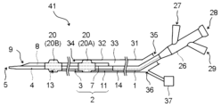
- FIG. 2 is a side view of the catheter system in a state in which the catheter shown in FIG. 1 is inserted into a medical elongated body (the medical elongated body is a cross-sectional view).
- 2 illustrates a side view of the distal portion of the catheter shown in FIG. 1.
- 2 illustrates a perspective view of the distal end of the catheter shown in FIG. 1 .
- FIG. 13 shows another example of a catheter used in the catheter and catheter system according to an embodiment of the present invention, and shows a side view of the catheter.
- FIG. 13 shows another example of a catheter used in the catheter and catheter system according to an embodiment of the present invention, and shows a side view of the catheter.
- FIG. 13 shows another example of a catheter used in the catheter and catheter system according to an embodiment of the present invention, and shows a side view of the
- FIG. 6 is a side view of the catheter system in a state in which the catheter shown in FIG. 5 is inserted into a medical elongated body (the medical elongated body is a cross-sectional view).
- 7 illustrates a side view of the distal portion of the catheter shown in FIG. 6.
- FIG. 13 shows another example of a catheter used in the catheter and catheter system according to an embodiment of the present invention, and shows a side view of the catheter.
- FIG. 9 is a side view of the catheter system in a state in which the catheter shown in FIG. 8 is inserted into a medical elongated body (the medical elongated body is a cross-sectional view).
- 1 depicts a variation of a side view of the distal end of the catheter.
- 1 depicts a variation of a side view of the distal end of the catheter.
- 1 depicts a variation of a side view of the distal end of the catheter.
- FIG. 1 shows a side view of an example of a catheter used in a catheter and a catheter system according to an embodiment of the present invention
- Fig. 2 shows a side view of the catheter system in which the catheter shown in Fig. 1 is inserted into a medical elongated body (the medical elongated body is a cross-sectional view)
- Fig. 3 shows a side view of the distal portion of the catheter shown in Fig. 1
- Fig. 4 shows a perspective view of the distal end portion of the catheter shown in Fig. 1.
- the catheter 1 has a liquid discharge port 5 and a liquid suction port 9.
- the catheter 1 can discharge liquid (e.g., cleaning liquid) from the liquid discharge port 5 to supply the liquid to a body lumen, and can suck up the liquid (cleaning liquid) supplied to the body lumen from the liquid suction port 9, as well as body fluids, mucus, foreign bodies, etc. that have accumulated in the body lumen.
- body lumen include the bile duct, pancreatic duct, intestine, esophagus, ureter, blood vessels, etc.
- the catheter 1 is suitable for use as a bile aspiration catheter.
- a bile aspiration catheter is used for aspirating bile by being inserted into the bile duct, and can aspirate bile that has accumulated in the bile duct while supplying liquid into the bile duct to clean the inside of the bile duct.
- Bile has a relatively high viscosity, and bacterially infected bile has an even higher viscosity.
- the catheter 1 has a shaft 2 extending in the longitudinal direction and a handle 26 provided proximally of the shaft 2.
- the shaft 2 is inserted into the body, and the user can operate the catheter 1 with the handle 26.
- the longitudinal direction is determined based on the extension direction of the shaft 2.
- the catheter 1 has a proximal side and a distal side as one and the other sides in the longitudinal direction.
- the proximal side refers to the direction toward the hand of the user of the catheter 1, i.e., the surgeon
- the distal side refers to the opposite direction from the proximal side, i.e., the direction toward the treatment target.
- the shaft 2 has a radial direction that is perpendicular to the longitudinal direction. In each drawing, the right side of the drawing corresponds to the proximal side, and the left side of the drawing corresponds to the distal side.
- the shaft 2 has a first tube 3 having a liquid discharge port 5 at its distal end, and a second tube 7 having a liquid suction port 9 at its distal end.
- the first tube 3 and the second tube 7 each extend in the longitudinal direction, and are preferably arranged side by side in the radial direction.
- the first tube 3 has a first lumen 4 as an inner cavity extending in the longitudinal direction
- the second tube 7 has a second lumen 8 as an inner cavity extending in the longitudinal direction.
- the first tube 3 and the second tube 7 are preferably integrated by welding or bonding to each other.
- the longitudinal length of the shaft 2 is, for example, preferably 1500 mm or more, more preferably 1800 mm or more, and preferably 3000 mm or less, more preferably 2800 mm or less.
- a liquid (cleaning liquid) to be supplied to the body lumen flows through the first lumen 4 of the first tube 3, and the liquid is discharged into the body lumen from the liquid outlet 5 at the distal end of the first tube 3.
- a liquid (cleaning liquid) to be supplied into the bile duct flows through the first lumen 4 of the first tube 3, and the liquid is discharged into the bile duct from the liquid outlet 5 at the distal end of the first tube 3. Therefore, it is preferable that the first tube 3 has a proximal opening, and that a liquid supply unit is provided in communication with the proximal opening of the first tube 3. Examples of the liquid supply unit include a syringe and a pump.
- the first lumen 4 may also serve as a guidewire lumen.
- the outer diameter of the shaft 2 can be reduced.
- bodily fluids can be aspirated and the body lumen can be washed without removing the guidewire, simplifying the procedure and shortening the surgical time.
- the liquid suction port 9 at the distal end of the second tube 7 sucks in the liquid (cleaning liquid) supplied to the body lumen, as well as body fluids, mucus, foreign bodies, etc. that have accumulated in the body lumen. If the catheter 1 is a bile suction catheter, bile, etc. that has accumulated in the bile duct is sucked in through the liquid suction port 9 at the distal end of the second tube 7 and discharged from the bile duct through the second lumen 8 of the second tube 7.
- a balloon 20 is provided on the shaft 2 outside the first tube 3 and the second tube 7, and the internal space of the second tube 7 is connected to the external space of the catheter 1 proximal to the proximal end of the balloon 20.
- the internal space of the second tube 7 is connected to the external space of the catheter 1 proximal to the proximal end of the balloon 20 and distal to the handle 26.
- the proximal end of the second tube 7 is located distal to the distal end of the handle 26, and the internal space of the second tube 7 is connected to the external space of the catheter 1 proximal to the proximal end of the balloon 20.
- the shaft 2 is inserted into the inner cavity 33 of a separate medical elongated body 31, the balloon 20 is expanded in the inner cavity 33 and abuts against the inner surface of the inner cavity 33, and the inner cavity 33 of the medical elongated body 31 is sucked from the proximal side, thereby allowing bodily fluids and the like to be sucked through the liquid suction port 9 of the second tube 7 of the catheter 1.
- the combination of the catheter 1 and the medical elongated body 31 is called a "catheter system,” and the present invention also provides a catheter system 41 having the catheter 1 and the medical elongated body 31.
- the medical elongated body 31 is not particularly limited as long as it has an inner cavity 33 into which the shaft 2 of the catheter 1 can be inserted and the inner cavity 33 can be aspirated from the proximal side.
- the medical elongated body 31 has a second shaft 32 extending in the longitudinal direction, and the inner cavity 33 is formed in the second shaft 32.
- the inner cavity 33 extends in the longitudinal direction, and the second shaft 32 has a distal opening 34 of the inner cavity 33 and a proximal insertion port 35.
- the longitudinal direction of the medical elongated body 31 is determined based on the extending direction of the second shaft 32, and when the shaft 2 of the catheter 1 is inserted into the inner cavity 33 of the second shaft 32 of the medical elongated body 31 for use, the longitudinal direction of the medical elongated body 31 coincides with the longitudinal direction of the catheter 1.
- the shaft 2 When using the balloon 20, the shaft 2 is inserted from the proximal insertion port 35 of the second shaft 32, the distal end of the shaft 2 is extended from the distal opening 34 of the second shaft 32, and the balloon 20 of the catheter 1 is expanded in the lumen 33 of the second shaft 32 to abut against the inner surface of the second shaft 32.
- the lumen 33 of the second shaft 32 is sucked from the proximal side, so that the lumen of the second tube 7 of the catheter 1 is depressurized, and bodily fluids, etc. can be sucked from the liquid suction port 9 at the distal end of the second tube 7.
- the sucked bodily fluids, etc. can pass through the second lumen 8, which is the lumen of the second tube 7 of the catheter 1, and further through the lumen 33 of the medical elongated body 31, and can be discharged outside the body.
- the catheter system 41 comprises a catheter 1 having a shaft 2 extending in the longitudinal direction, and a medical elongated body 31 having a second shaft 32 extending in the longitudinal direction, the shaft 2 of the catheter 1 being inserted into the lumen 33 of the second shaft 32.
- the lumen 33 of the second shaft 32 can be aspirated from the proximal side, the shaft 2 having a first tube 3 having a liquid discharge port 5 at its distal end and a second tube 7 having a liquid suction port 9 at its distal end, and a balloon 20 is provided on the outside of the first tube 3 and the second tube 7, which contacts the inner surface of the second shaft 32 when expanded.
- the longitudinal direction is determined based on the extension direction of the shaft 2 of the catheter 1.
- the catheter system 41 is used by inserting the shaft 2 of the catheter 1 from the proximal insertion port 35 of the second shaft 32 and extending the distal end of the shaft 2 from the distal opening 34 of the second shaft 32.
- the shaft 2 of the catheter 1 is inserted into the second shaft 32 of the medical elongated body 31, and the user can operate the catheter 1 with the handle 26.
- the catheter system 41 By inserting the shaft 2 of the catheter 1 into the inner cavity 33 of the second shaft 32 of the medical elongated body 31 and extending the shaft 2 distal to the distal end of the second shaft 32 and using the catheter system 41, it is possible to discharge liquid from the distal end of the first tube 3 of the catheter 1 or to aspirate liquid from the distal end of the second tube 7.
- the catheter system 41 can wash the body lumen by inserting the shaft 2 of the catheter 1 and the second shaft 32 of the medical elongated body 31 into the body lumen.
- the proximal insertion port 35 of the second shaft 32 may be an opening or an elastic membrane capable of forming an opening.
- the elastic membrane may have a slit or pinhole formed therein, which makes it easier to insert the shaft 2 of the catheter 1 into the lumen 33 of the second shaft 32 from the proximal insertion port 35 and can increase the airtightness of the lumen 33 in the proximal portion of the second shaft 32.
- the second shaft 32 is preferably provided with a suction port 36 in the proximal portion, and is configured so that the inner cavity 33 of the second shaft 32 can be sucked through the suction port 36.
- the suction port 36 is preferably provided in the proximal 1/3 portion of the second shaft 32, and more preferably in the proximal 1/4 portion.
- the longitudinal length of the second shaft 32 is, for example, preferably 1500 mm or more, more preferably 1800 mm or more, and preferably 3000 mm or less, and more preferably 2800 mm or less.
- the longitudinal length of the second shaft 32 is preferably shorter than the longitudinal length of the shaft 2 of the catheter 1.
- the shape of the inner cavity 33 of the second shaft 32 is not particularly limited, and examples include a circle, an ellipse, an oval, an egg, a polygon, and an irregular shape.
- the medical elongated body 31 is preferably provided with a suction mechanism 37 in communication with the inner cavity 33 of the second shaft 32.
- the second shaft 32 is preferably configured so that the inner cavity 33 branches in the proximal portion, one of which is connected to the proximal opening 35 and the other is connected to the suction mechanism 37.
- the inner cavity 33 of the second shaft 32 branches at the suction port 36, and the suction mechanism 37 is provided in communication with the suction port 36.
- An endoscope is preferably used as the medical elongated body 31 having the suction mechanism 37.
- Endoscopes equipped with a suction pump are known, and the suction pump is provided in the proximal portion of the endoscope and communicates with the forceps channel of the endoscope.
- the suction pump allows the forceps channel of the endoscope to be sucked from the proximal side.
- the medical elongated body 31 may be a guiding catheter, etc.
- the balloon 20 of the catheter 1 will be described in detail.
- the balloon 20 is disposed outside the first tube 3 and the second tube 7 in a vertical cross section of the longitudinal direction of the shaft 2.
- the balloon 20 has a longitudinal direction and a radial direction, and is formed in a cylindrical shape with openings on the proximal and distal sides.
- the longitudinal direction of the balloon 20 corresponds to the longitudinal direction of the shaft 2.
- the radial direction of the balloon 20 refers to the direction perpendicular to the longitudinal direction, extending radially from the center of the balloon 20.
- the shape of the balloon 20 in the expanded state is not particularly limited, but as shown in FIG. 3, it is preferable that the balloon 20 has at least a straight tube portion 23, and that the straight tube portion 23 is formed to be expandable and contractible. If the balloon 20 is formed in this manner, when the balloon 20 is expanded in the lumen 33 of the second shaft 32, the straight tube portion 23 comes into sufficient contact with the inner surface of the second shaft 32, and the balloon 20 is likely to come into contact with the inner surface of the second shaft 32 in a liquid-tight manner.
- the balloon 20 has a proximal sleeve portion 21 located proximal to the straight tube portion 23 and a distal sleeve portion 25 located distal to the straight tube portion 23, and it is preferable that the inner surface of the proximal sleeve portion 21 and the inner surface of the distal sleeve portion 25 are joined to the outer surface of the shaft 2. This allows the balloon 20 to be formed so that the portion distal to the proximal sleeve portion 21 and proximal to the distal sleeve portion 25 can be expanded and contracted.
- the balloon 20 further preferably has a proximal tapered portion 22 between the straight tube portion 23 and the proximal sleeve portion 21 in the longitudinal direction, and a distal tapered portion 24 between the straight tube portion 23 and the distal sleeve portion 25. It is preferable that the balloon 20 is formed so that the radial length (outer diameter) is greatest at the straight tube portion 23, and that the proximal tapered portion 22 and the distal tapered portion 24 are formed so that the outer diameter decreases with increasing distance from the straight tube portion 23.
- the outer diameter of the proximal and distal ends of the balloon 20 can be reduced when the balloon 20 is deflated, thereby reducing the step between the shaft 2 and the balloon 20, and the balloon 20 can be easily inserted into the inner cavity 33 of the second shaft 32 when the balloon 20 is deflated.
- the expandable and contractable portion of the balloon 20, i.e., the portion distal to the proximal sleeve portion 21 and proximal to the distal sleeve portion 25, is referred to as the expandable portion of the balloon 20.
- the distal end of the expandable portion of the balloon 20 is preferably located in a range of 20 cm to 50 cm proximal to the distal end of the shaft 2.
- the catheter 1 is a bile aspiration catheter
- the distal end of the expandable portion of the balloon 20 located most proximal is located in a range of 20 cm to 50 cm proximal to the distal end of the shaft 2.
- the distal end of the expandable portion of the balloon 20 is more preferably located in a range of 25 cm to 45 cm proximal to the distal end of the shaft 2, and even more preferably located in a range of 30 cm to 40 cm.
- the catheter 1 When the catheter 1 is introduced into the bile duct, it is usually introduced into the bile duct through the forceps channel of the endoscope, but in this case, the forceps channel of the endoscope can be the lumen 33 of the medical elongated body 31.
- the tip of the endoscope is transported to the vicinity of the entrance of the bile duct, the shaft 2 of the catheter 1 is inserted into the forceps channel of the endoscope, and the catheter 1 is extended from the distal opening of the forceps channel. This allows the catheter 1 to be inserted into the bile duct from the entrance of the bile duct opened on the side of the inner wall of the duodenum.
- the distal end of the expandable portion of the balloon 20 is located within a range of 20 cm to 50 cm proximal to the distal end of the shaft 2, it becomes easy to insert the catheter 1 deep into the bile duct by extending the part of the catheter 1 distal to the balloon 20 from the distal opening of the forceps channel while positioning the balloon 20 in the forceps channel of the endoscope.
- the balloon 20 by expanding the balloon 20 and abutting it against the inner surface of the forceps channel of the endoscope (i.e., the inner cavity 33 of the second shaft 32 of the medical elongated body 31), and discharging liquid (cleaning liquid) from the liquid discharge port 5 of the first tube 3 into the bile duct and sucking it from the liquid suction port 9 of the second tube 7, the inside of the bile duct can be cleaned and bile and gallstones accumulated in the bile duct can be suitably sucked up.
- the forceps channel of the endoscope i.e., the inner cavity 33 of the second shaft 32 of the medical elongated body 31
- the distal end of the expandable portion of the balloon 20 may be located within a range of less than 20 cm proximal to the distal end of the shaft 2, but distal to the liquid discharge port 5 of the first tube 3 and the liquid suction port 9 of the second tube 7.
- the balloon 20 is preferably made of a resin.
- resins constituting the balloon 20 include polyolefin resins such as polyethylene, polypropylene, and ethylene-propylene copolymer, polyester resins such as polyethylene terephthalate and polyester elastomer, polyurethane resins such as polyurethane and polyurethane elastomer, polyamide resins such as polyphenylene sulfide resin, polyamide and polyamide elastomer, fluorine-based resins, silicone resins, and natural rubbers such as latex rubber. These may be used alone or in combination of two or more. Among these, polyamide resins, polyester resins, and polyurethane resins are preferably used.
- elastomer resins are preferably used in terms of thinning and flexibility of the balloon 20.
- nylon 12 and nylon 11 are examples of polyamide resins suitable for the balloon 20, and nylon 12 is preferably used because it is relatively easy to mold during blow molding.
- polyamide elastomers such as polyether ester amide elastomers and polyamide ether elastomers are preferably used in terms of thinning and flexibility of the balloon 20. It is also preferable to use polyether ester amide elastomer because it has high yield strength and provides good dimensional stability to the balloon 20.
- the balloon 20 is configured so that fluid is supplied to the inside through the shaft 2, and the expansion and contraction of the balloon 20 can be controlled using an indeflator (a balloon pressurizer/depressurizer).
- the fluid may be a liquid or gas, or it may be a pressurized fluid pressurized by a pump or the like.
- the fluid supplied to the inside of the balloon 20 is referred to as the "balloon expansion fluid.”
- the shaft 2 further has a third tube 11, and the distal opening 13 of the third tube 11 is preferably connected to the internal space of the balloon 20.
- the third tube 11 has a third lumen 12 as an inner cavity extending in the longitudinal direction, and extends from the proximal part of the shaft 2 to the inside of the balloon 20.
- the first tube 3 and the second tube 7 extend distally from the distal end of the balloon 20, the third tube 11 extends to the balloon 20, and the distal opening 13 of the third tube 11 is located in the internal space of the balloon 20.
- the third tube 11 is arranged, for example, radially alongside the first tube 3 and the second tube 7.
- the first tube 3, the second tube 7, and the third tube 11 are integrated together by welding or bonding.
- the third tube 11 may be arranged in the inner cavity of the protective tube 14 together with the first tube 3, proximal to the proximal end of the second tube 7, and the first tube 3 and the third tube 11 may be integrated by the protective tube 14.
- the first tube 3 may be arranged in the third lumen 12 of the third tube 11, and the first tube 3 may be formed to extend distally beyond the distal end of the third tube 11.
- the first tube 3 and the second tube 7 will be described in detail.
- the second tube 7 extends proximally and distally from the balloon 20, and is configured such that the internal space of the second tube 7, i.e., the second lumen 8, is connected to the external space of the catheter 1 proximally from the proximal end of the balloon 20. Therefore, when the shaft 2 of the catheter 1 is inserted into the inner cavity 33 of the medical elongated body 31 for use, the second tube 7's second lumen 8 is connected to the inner cavity 33 of the second shaft 32 proximally from the proximal end of the balloon 20.
- the second tube 7 is configured to extend proximally beyond the proximal end of the balloon 20 and have a proximal opening 10 at the proximal end of the second tube 7, as shown in FIG. 1, for example.
- the proximal opening 10 of the second tube 7 faces the outside of the catheter 1.
- the second tube 7 may extend proximally beyond the proximal end of the balloon 20, and a hole communicating with the outside of the catheter 1 may be formed on the side of the second tube 7 proximal to the balloon 20. In this case, the proximal opening may not be provided at the proximal end of the second tube 7.
- the balloon 20 is expanded by the inner cavity 33 of the second shaft 32 to abut against the inner surface of the inner cavity 33, and the inner cavity 33 of the second shaft 32 is sucked from the proximal side, so that the second lumen 8 of the second tube 7 is sucked from the proximal side, and bodily fluids, etc. can be sucked from the liquid suction port 9 of the second tube 7.
- the second tube 7 is in the former form, that is, that the second tube 7 extends proximally beyond the proximal end of the balloon 20 and has a proximal opening 10 at the proximal end of the second tube 7.
- the proximal end (proximal opening 10) of the second tube 7 is located distal to the distal end of the handle 26.
- the proximal opening 10 of the second tube 7 is preferably located in the distal 1/3 of the shaft 2, and more preferably in the distal 1/4 of the shaft 2.
- the second tube 7 may be formed so that the length from the proximal end of the balloon 20 to the proximal opening 10 of the second tube 7 is shorter than the length from the distal end of the balloon 20 to the liquid suction port 9 of the second tube 7.
- the position of the proximal opening 10 of the second tube 7 is relatively distal to the proximal end of the balloon 20, thereby shortening the length of the second tube 7 and suppressing pressure loss in the second lumen 8 of the second tube 7. This allows body fluids and the like to be effectively sucked through the liquid suction port 9 of the second tube 7.
- the proximal opening 10 of the second tube 7 is preferably located within 100 mm proximal to the proximal end of the balloon 20 (preferably the proximal end of the expandable part of the balloon 20), more preferably within 50 mm, even more preferably within 30 mm, and particularly preferably within 10 mm.
- the hole is preferably also formed at the same position as the proximal opening 10.
- the cross-sectional area of the second lumen 8 of the second tube 7 is preferably larger than the cross-sectional area of the first lumen 4 of the first tube 3. This makes it possible to suppress pressure loss in the second lumen 8 of the second tube 7, and allows body fluids, etc. to be effectively sucked through the liquid suction port 9, while making it difficult for the second lumen 8 to become clogged when sucking body fluids, etc. In addition, it becomes easier to forcefully eject the cleaning liquid from the liquid ejection port 5 of the first lumen 4, making it easier to clean deeper into the body lumen.
- the cross-sectional area of the second lumen 8 is, for example, preferably 1.1 times or more, more preferably 1.2 times or more, and preferably 4.0 times or less, more preferably 3.0 times or less, and even more preferably 2.5 times or less of the cross-sectional area of the first lumen 4.
- the outer edge of the liquid suction port 9, i.e., the distal end edge of the second tube 7, is preferably formed in an inclined shape. Specifically, when the side of the shaft 2 where the second tube 7 is arranged is the upper side and the side where the first tube 3 is arranged is the lower side, the outer edge of the liquid suction port 9 is preferably inclined distally from the upper side to the lower side. If the liquid suction port 9 is formed in this manner, the size of the liquid suction port 9 can be made larger, making it easier to suck in body fluids, etc. Furthermore, since the outer edge of the liquid suction port 9 is inclined distally from the upper side to the lower side, it is easier to suck in body fluids, etc. that are proximal to the liquid suction port 9. The outer edge of the liquid suction port 9 may be formed in a straight line or in a non-straight line.
- the outer edge of the liquid discharge port 5, i.e., the distal end edge of the first tube 3, is formed so as to extend perpendicular to the longitudinal direction. It is also preferable that the outer edge of the liquid discharge port 5 is chamfered or rounded in side view. If the outer edge of the liquid discharge port 5 is formed in this manner, it is less likely to damage the body lumen when the shaft 2 is inserted into the body lumen.
- the shaft 2 is preferably arranged such that the liquid suction port 9 is located proximal to the liquid discharge port 5. This allows the liquid discharge port 5 to be provided at the tip of the shaft 2, making it easier to insert the distal end of the first tube 3 deeper into the body lumen for cleaning and aspirating.
- the liquid discharge port 5 By forming the liquid discharge port 5 at the distal end of the first tube 3, the cleaning liquid carried to the distal end of the first tube 3 through the first lumen 4 is discharged distally from the liquid discharge port 5, making it possible to clean the body lumen distal to the liquid discharge port 5.
- the body fluid in the body lumen can be diluted and its viscosity can be reduced by discharging the cleaning liquid from the liquid discharge port 5 into the body lumen.
- the liquid suction port 9 proximal to the liquid discharge port 5 it becomes easier to aspirate body fluids and the like that have accumulated in the body lumen.
- the liquid suction port 9 proximal to the liquid discharge port 5 it becomes easier to aspirate body fluids and the like that have been diluted with the cleaning liquid and have a reduced viscosity from the liquid suction port 9.
- the aspirated body fluids and the like are less likely to clog the second lumen 8.
- the length of the second tube 7 can be shortened to suppress pressure loss in the second lumen 8 of the second tube 7.
- the catheter 1 is a bile suction catheter
- Bile can be aspirated particularly effectively.
- Bile has a relatively high viscosity, and if it is bacterially infected, the viscosity will be even higher.
- the bile accumulated in the bile duct is diluted and the viscosity can be reduced.
- the liquid suction port 9 is located proximal to the liquid discharge port 5, it becomes easier to aspirate bile whose viscosity has been reduced by the cleaning liquid from the liquid suction port 9. This makes it easier to aspirate bile from the liquid suction port 9.
- the liquid suction port 9 is preferably located 3 mm or more proximal to the liquid discharge port 5, more preferably 4 mm or more, even more preferably 5 mm or more, and preferably 30 mm or less, more preferably 20 mm or less, and even more preferably 15 mm or less.
- the separation distance between the liquid suction port 9 and the liquid discharge port 5 is determined by measuring the longitudinal separation distance between the distal end of the liquid suction port 9 and the proximal end of the liquid discharge port 5.
- the liquid discharge port 5 is located 10 mm or less distal to the liquid suction port 9. This prevents the length of the portion of the distal end of the shaft 2 that is distal to the liquid suction port 9 (i.e., the length of the portion where the first tube 3 is present but the second tube 7 is not present) from becoming too long, making it easier to ensure the rigidity of the distal end of the shaft 2 and improving the deliverability of the catheter 1.
- the positioning of the liquid discharge port 5 and liquid suction port 9 as described above makes it easier to clean deeper into the bile duct and makes it easier to aspirate bile that has accumulated deep inside the bile duct, reducing the amount of bile left behind. It also prevents undiluted bile from being aspirated, making it easier to aspirate bile that has been diluted with a cleaning solution.
- the liquid discharge port 5 is preferably located 8 mm or less distal to the liquid suction port 9, and more preferably 7 mm or less.
- the outer diameter of the shaft 2 distal to the balloon 20 is 4.0 mm or less. Since the intrahepatic bile duct has a narrower internal space than the common bile duct, it is difficult to insert a shaft 2 having a maximum outer diameter of, for example, 5.0 mm into the intrahepatic bile duct located deep inside the bile duct.
- the shaft 2 can be inserted through the common bile duct to the deep inside the intrahepatic bile duct.
- the maximum outer diameter of the shaft 2 distal to the balloon 20 is preferably 3.5 mm or less, and more preferably 3.0 mm or less.
- the lower limit of the maximum outer diameter of the shaft 2 proximal to the proximal end of the liquid suction port 9 and distal to the balloon 20 is preferably 1.0 mm or more, more preferably 1.3 mm or more, and even more preferably 1.5 mm or more. This improves the deliverability of the catheter 1.
- the shaft 2 has a tapered section 18 distal to the liquid suction port 9, where the outer diameter decreases toward the distal end.
- the first tube 3 has a tapered section 18 distal to the liquid suction port 9, where the outer diameter decreases toward the liquid discharge port 5.
- the handle 26 of the catheter 1 will now be described.
- the handle 26 is provided on the catheter 1 proximal to the shaft 2.
- the handle 26 is provided for operating the catheter 1, and it is preferable that it is not inserted into the lumen 33 of the second shaft 32 of the medical elongated body 31 when the catheter 1 is in use.
- the proximal end of the first tube 3 is connected to the handle 26, and if a third tube 11 is provided on the catheter 1, it is preferable that the proximal end of the third tube 11 is also connected to the handle 26.
- the handle 26 preferably has, for example, a liquid supply port 27 that communicates with the first lumen 4, and a liquid supply unit is connected to the liquid supply port 27.
- the handle 26 preferably further has a guidewire port 28.
- the guidewire port 28 is preferably provided in communication with the first lumen 4.
- an internal passage communicating with the first lumen 4 branches inside the handle 26, and one of the branches is connected to the liquid supply port 27, and the other is connected to the guidewire port 28.
- the handle 26 may further have an auxiliary port into which other medical tools can be inserted.
- An example of the other medical tool is a brush for cytology, which allows specimen collection for cytology.
- the handle 26 preferably has a fluid injection port 29 that communicates with the third lumen 12 and is used to introduce balloon expansion fluid.
- an indeflator is connected to the fluid injection port 29.
- a check valve may be provided in the internal passage of the handle 26.
- a check valve in the internal passage connecting the first lumen 4 of the handle 26 and the liquid supply port 27, liquid can be allowed to flow in one direction, from the liquid supply port 27 to the first lumen 4.
- the catheter 1 may use the first tube 3 instead of the third tube 11 as a means for supplying balloon expansion fluid to the inside of the balloon 20. Examples of the configuration of a catheter configured in this way are shown in Figures 5 to 7.
- FIG. 5 shows another example of the configuration of a catheter used in a catheter and catheter system according to an embodiment of the present invention, showing a side view of the catheter
- FIG. 6 shows a side view of the catheter system in which the catheter shown in FIG. 5 has been inserted into a medical elongated body (the medical elongated body is a cross-sectional view)
- FIG. 7 shows a side view of the distal portion of the catheter shown in FIG. 6.
- the catheter 1 may have a hole 6 formed on the side of the first tube 3 that communicates with the internal space of the balloon 20. That is, the balloon 20 may be provided on the outside of the first tube 3, but the hole 6 may be formed in a portion of the first tube 3 that is located in the internal space of the balloon 20. If the shaft 2 is configured in this manner, by supplying liquid to the first lumen 4 of the first tube 3, the balloon 20 expands and liquid can be discharged from the liquid discharge port 5 at the distal end of the first tube 3. It is also possible to reduce the diameter of the shaft 2.
- the handle 26 of the catheter 1 does not need to have a fluid injection port 29 as shown in Figures 1 and 2.
- the catheter 1 may have multiple balloons 20 on the shaft 2.
- An example of a catheter configured in this way is shown in Figures 8 and 9.
- Figures 8 and 9 show an example of a catheter 1 shown in Figures 1 to 4, in which multiple balloons 20 are provided on the shaft 2.
- FIG. 8 shows another example of the configuration of a catheter used in a catheter and catheter system according to an embodiment of the present invention, showing a side view of the catheter
- FIG. 9 shows a side view of the catheter system in which the catheter shown in FIG. 8 has been inserted into a medical elongated body (the medical elongated body is a cross-sectional view).
- the medical elongated body is a cross-sectional view.
- multiple balloons 20 may be provided at different positions in the longitudinal direction of the shaft 2.
- the balloons 20 include a first balloon 20A and a second balloon 20B located distal to the first balloon 20A, but another balloon may be provided distal to the second balloon 20B.
- Both the first balloon 20A and the second balloon 20B are configured to have a balloon expansion fluid supplied to the inside through the shaft 2.
- the shaft 2 has a third tube 11 for circulating the balloon expansion fluid, and the third lumen 12 of the third tube 11 is connected to the internal space of the first balloon 20A and the internal space of the second balloon 20B, respectively.
- the third tube 11 extends from the proximal part of the shaft 2 through the inside of the first balloon 20A to the inside of the second balloon 20B.
- a hole is formed on the side of the third tube 11, and the distal opening 13 of the third tube 11 is located in the internal space of the second balloon 20B.
- the first balloon 20A and the second balloon 20B can be expanded by supplying the balloon expansion fluid through the third tube 11.
- the first balloon 20A and the second balloon 20B can be deflated by withdrawing the balloon expansion fluid from the inside of the first balloon 20A and the inside of the second balloon 20B through the third tube 11.
- the first balloon 20A When the catheter 1 is used, the first balloon 20A is located in the inner cavity 33 of the second shaft 32 of the medical elongated body 31, and the second balloon 20B is used to extend from the distal opening 34 of the medical elongated body 31.
- the catheter 1 When the first balloon 20A and the second balloon 20B are inflated, the catheter 1 can be used so that the first balloon 20A contacts the inner surface of the second shaft 32 and the second balloon 20B contacts the inner wall of the body lumen.
- the catheter 1 By configuring the catheter 1 in this way, when the cleaning liquid is discharged from the liquid discharge port 5 into the body lumen, the cleaning liquid is blocked by the second balloon 20B, and the body fluids and mucus in the body lumen can be efficiently diluted. Therefore, the body lumen can be effectively washed and suctioned.
- Figures 8 and 9 show an example configuration in which multiple balloons 20 are provided on the shaft 2 of the catheter 1 shown in Figures 1 to 4, but as shown in Figures 5 to 7, the shaft 2 of the catheter 1 may not have the third tube 11, and a hole communicating with the internal space of the first balloon 20A and a hole communicating with the internal space of the second balloon 20B may be formed on the side of the first tube 3.
- the outer diameter of the shaft 2 may be set appropriately depending on the application of the catheter 1, i.e., the type of body lumen into which the catheter 1 is inserted.
- the outer diameter of the shaft 2 is preferably 1.2 mm or more, more preferably 1.3 mm or more, even more preferably 1.4 mm or more, and preferably 8.0 mm or less, more preferably 7.0 mm or less, and even more preferably 6.0 mm or less.
- the outer diameter of the shaft 2 may be even smaller, for example, 4.0 mm or less, 3.6 mm or less, or 3.2 mm or less.
- the inner diameters of the first lumen 4, the second lumen 8, and the third lumen 12 are preferably 1.0 mm or more, more preferably 1.1 mm or more, even more preferably 1.3 mm or more, and preferably 3.5 mm or less, more preferably 3.0 mm or less, and even more preferably 2.5 mm or less.
- the inner diameters of the first lumen 4, the second lumen 8, and the third lumen 12 may be even smaller, for example, 2.2 mm or less, 2.0 mm or less, or 1.9 mm or less.
- the shapes of the outer edge of the shaft 2, the outer edge of the first tube 3, the outer edge of the second tube 7, the outer edge of the third tube 11, the first lumen 4, the second lumen 8, and the third lumen 12 are not particularly limited, and examples thereof include circular, elliptical, oval, egg-shaped, polygonal, and amorphous.
- the shape of the outer edge of the shaft 2 and the shapes of the first lumen 4, the second lumen 8, and the third lumen 12 are other than circular
- the outer diameter of the shaft 2 and the inner diameters of the first lumen 4, the second lumen 8, and the third lumen 12 described above refer to the average values of the major and minor axes.
- the major axis of the outer edge of the shaft 2 refers to the length in the major axis direction of the outer edge of the shaft 2 (the maximum diameter of the outer edge), and the minor axis of the outer edge of the shaft 2 refers to the longest length among the lengths in the minor axis direction perpendicular to the major axis direction of the shaft 2.
- the shapes of the outer edges of the shaft 2, the first tube 3, the second tube 7, the third tube 11, the first lumen 4, the second lumen 8, and the third lumen 12 are preferably circular, oval, elliptical, or egg-shaped.
- the inner and outer diameters of the first tube 3 may be substantially the same throughout the entire length, or may be different between some parts in the longitudinal direction.
- the inner and outer diameters of the second tube 7 and the third tube 11 may also be substantially the same throughout the entire length, or may be different between some parts in the longitudinal direction.
- the first tube 3 may be formed such that the inner diameter of the first tube 3 at the proximal portion of the shaft 2 is larger than the inner diameter of the first tube 3 at the distal portion of the shaft 2.
- the first tube 3, the second tube 7, the third tube 11, and the protective tube 14 can be made of resin.
- resins include polyolefin resins such as polyethylene and polypropylene, polyamide resins such as nylon, polyester resins such as polyethylene terephthalate, aromatic polyether ketone resins such as PEEK, polyether polyamide resins, polyurethane resins, polyimide resins, polyamide imide resins, fluorine-based resins such as PTFE, PFA, and ETFE, polyvinyl chloride resins, and synthetic resins such as silicone resins.
- polyolefin resins such as polyethylene and polypropylene
- polyamide resins such as nylon
- polyester resins such as polyethylene terephthalate
- aromatic polyether ketone resins such as PEEK
- polyether polyamide resins polyurethane resins
- polyimide resins polyimide resins
- polyamide imide resins fluorine-based resins
- fluorine-based resins such as
- the first tube 3, the second tube 7, the third tube 11, and the protective tube 14 may be made of a single layer or may be made of multiple layers.
- the first tube 3, the second tube 7, the third tube 11, and the protective tube 14 may have a portion in the longitudinal direction made of a single layer and another portion made of multiple layers.
- the first tube 3, the second tube 7, the third tube 11, and the protective tube 14 may have a reinforcing layer.
- the reinforcing layer can increase the rigidity of the shaft 2. It is preferable that the reinforcing layer is disposed between an inner layer and an outer layer made of resin.
- the reinforcing layer can be made of metal wire, fiber, etc.
- materials that can be used to make the metal wire include stainless steel, titanium, nickel-titanium alloy, cobalt-chromium alloy, and tungsten alloy. Of these, stainless steel is preferable.
- the metal wire can be a solid wire or a twisted wire.
- fibers include polyarylate fiber, aramid fiber, ultra-high molecular weight polyethylene fiber, PBO fiber, and carbon fiber.
- the fiber can be a monofilament or a multifilament.
- the shape of the reinforcing layer is not particularly limited, but a spiral, mesh, or braided shape is preferred. Of these, a braided shape is more preferred because the reinforcing layer can effectively increase the rigidity of the shaft 2.
- the shaft 2 may contain a radiopaque material to make it easier to confirm its position under X-ray fluoroscopy, etc.
- radiopaque materials include lead, barium, iodine, tungsten, gold, platinum, iridium, platinum-iridium alloy, stainless steel, titanium, cobalt-chromium alloy, palladium, and tantalum.
- the outer surface of the shaft 2 may be coated with a hydrophilic polymer. This makes it easier to insert the shaft 2 into the forceps channel from the forceps port of the endoscope.
- hydrophilic polymers include polyethylene glycol, poly 2-hydroxyethyl methacrylate, polyacrylamide, polyvinylpyrrolidone, and maleic anhydride copolymers such as methyl vinyl ether maleic anhydride copolymers.
- the outer edge of the liquid suction port 9 has an inclined portion that slopes linearly from the top to the bottom toward the distal side, and a notch or a protrusion may be formed on the inclined portion.
- the inclined portion may have either a notch or a protrusion, or both. If the outer edge of the liquid suction port 9 is formed in this manner, it becomes less likely that foreign matter such as gallstones will become stuck in the liquid suction port 9 or that the liquid suction port 9 will become blocked by foreign matter.
- Figure 10 shows an example in which a notch 16 is provided on the outer edge of the liquid suction port 9.
- the outer edge of the liquid suction port 9 has an inclined portion 15 formed in a straight line from the top to the bottom on the distal side, and a notch 16 is formed in the inclined portion 15.
- the outer edge of the liquid suction port 9 is formed to overlap with an imaginary line connecting the upper and lower ends of the liquid suction port 9, and in the notch portion 16, the outer edge of the liquid suction port 9 is located proximal to the imaginary line. Note that if a protrusion is formed on the inclined portion 15, the outer edge of the liquid suction port 9 is located distal to the imaginary line connecting the upper and lower ends of the liquid suction port 9 at the protruding portion.
- a plurality of protrusions 17 may be provided on the side of the second tube 7 near the proximal side of the liquid suction port 9.
- the protrusions 17 may be provided on the outer surface of the second tube 7 near the proximal side of the liquid suction port 9 in this manner, foreign matter such as gallstones is less likely to accumulate near the proximal side of the liquid suction port 9, making it more difficult for foreign matter to enter the liquid suction port 9. Even if foreign matter accumulates near the proximal side of the liquid suction port 9, bodily fluids and the like proximal to the liquid suction port 9 can easily be sucked through the liquid suction port 9 by passing through the gaps between the protrusions 17.
- the protrusion 17 is preferably provided in the vicinity of the proximal side of the liquid suction port 9 in a range proximal to the distal end of the liquid suction port 9 and distal to a point 50 mm proximal to the proximal end of the liquid suction port 9 in the longitudinal direction of the shaft 2.
- the protrusion 17 may be provided in at least a part of this range. It is also preferable that the protrusion 17 is not provided distally or proximally to this range.
- the protrusion 17 is provided in a range proximal to the distal end of the liquid suction port 9 and distal to a point 30 mm proximal to the proximal end of the liquid suction port 9, and even more preferable that the protrusion 17 is provided in a range proximal to the distal end of the liquid suction port 9 and distal to a point 20 mm proximal to the proximal end of the liquid suction port 9.
- the length of the protrusion 17 in a direction perpendicular to the longitudinal direction of the shaft 2 is preferably at least 0.02 times the outer diameter of the second tube 7 near the proximal side of the liquid suction port 9, more preferably at least 0.04 times, and preferably at most 0.15 times, and more preferably at most 0.10 times.
- the height of the protrusion 17 is preferably 0.02 times or more, more preferably 0.04 times or more, the outer diameter of the second tube 7 near the proximal side of the liquid suction port 9.
- the height of the protrusion 17 is preferably 0.15 times or less, more preferably 0.10 times or less, and even more preferably 0.08 times or less, the outer diameter of the second tube 7 near the proximal side of the liquid suction port 9. This prevents the protrusion 17 from being formed excessively large, making it easier to insert the shaft 2 deep into the body lumen.
- multiple protrusions 17 are arranged on the outer surface of the second tube 7 at different circumferential positions of the second tube 7.
- the protrusions 17 are arranged at three or more different circumferential positions of the second tube 7, more preferably four or more positions, and even more preferably five or more positions.
- multiple protrusions 17 are arranged on the outer surface of the second tube 7 at different longitudinal positions of the second tube 7.
- the protrusions 17 may be arranged at two or more different longitudinal positions of the second tube 7, or may be arranged at three or more different positions.
- the first lumen 4 has a constriction portion 19 at its distal end, and the cross-sectional area of the first lumen 4 at the constriction portion 19 may be formed narrower than the distal and proximal sides.
- the cleaning liquid can be discharged from the liquid discharge port 5 while spreading radially toward the distal side. This makes it easier to wash away bodily fluids and mucus adhering to the inner wall of the body lumen.
- the catheter 1 is a bile aspiration catheter, it is possible to clean deeper inside the bile duct and it is easier to wash away bile adhering to the inner wall of the bile duct.
- the constriction portion 19 is preferably formed at the distal end of the first lumen 4, proximal to the liquid outlet 5 and distal to the liquid suction port 9.
- the constriction portion 19 refers to the portion at the distal end of the first lumen 4 where the cross-sectional area is narrowest. By forming the constriction portion 19 in this manner, the cleaning liquid is more easily discharged from the liquid outlet 5 to the distal side while spreading in the radial direction.
- the constriction portion 19 is also preferably located 1 mm or more proximal to the liquid outlet 5 (specifically, the proximal end of the liquid outlet 5), more preferably 2 mm or more, and preferably 15 mm or less, more preferably 12 mm or less, and even more preferably 10 mm or less.
- the liquid discharged from the liquid discharge port 5 is preferably saline.
- the catheter 1 is a bile suction catheter
- the bile in the bile duct can be aspirated from the liquid suction port 9 while being diluted with saline, allowing the inside of the bile duct to be effectively cleaned.
- the formation of stones and stagnation of bile can be suppressed by cleaning the inside of the bile duct.
- saline As the cleaning liquid, it is possible to efficiently aspirate bile due to the difference in specific gravity with bile.
- ERCP endoscopic retrograde cholangiopancreatography
- the patient is usually treated in the prone or left lateral position, in which case the entrance to the bile duct is located above the inside of the bile duct.
- catheter 1 When using catheter 1 in this state to expel saline from liquid outlet 5, saline has a lighter specific gravity than bile, so when saline flows deep into the bile duct, it rises to the top as the supernatant, allowing the bile to be efficiently mixed with and diluted. Therefore, by aspirating the diluted bile from liquid suction port 9, the bile in the bile duct can be efficiently removed.
- the discharge of liquid from the liquid discharge port 5 and the suction from the liquid suction port 9 may be performed at the same time, at different times, or alternately.
- the catheter 1 is a bile suction catheter
- cleaning the inside of the bile duct in this manner allows the bile in the bile duct to be efficiently suctioned and also prevents the internal pressure in the bile duct from building up excessively. This makes it possible to suppress the occurrence of sepsis caused by infected bile flowing through the liver into the blood vessels of the entire body.
- a contrast agent may be discharged from the liquid discharge port 5.
- a contrast agent may be subsequently injected into the body lumen from the liquid discharge port 5, making it easier to perform image diagnosis of the body lumen.
Landscapes
- Health & Medical Sciences (AREA)
- Heart & Thoracic Surgery (AREA)
- Life Sciences & Earth Sciences (AREA)
- Hematology (AREA)
- Engineering & Computer Science (AREA)
- Anesthesiology (AREA)
- Biomedical Technology (AREA)
- Animal Behavior & Ethology (AREA)
- General Health & Medical Sciences (AREA)
- Public Health (AREA)
- Veterinary Medicine (AREA)
- Pulmonology (AREA)
- Biophysics (AREA)
- Child & Adolescent Psychology (AREA)
- Vascular Medicine (AREA)
- Media Introduction/Drainage Providing Device (AREA)
Priority Applications (1)
| Application Number | Priority Date | Filing Date | Title |
|---|---|---|---|
| JP2024576346A JPWO2024166890A1 (https=) | 2023-02-10 | 2024-02-06 |
Applications Claiming Priority (4)
| Application Number | Priority Date | Filing Date | Title |
|---|---|---|---|
| JP2023018861 | 2023-02-10 | ||
| JP2023-018860 | 2023-02-10 | ||
| JP2023018860 | 2023-02-10 | ||
| JP2023-018861 | 2023-02-10 |
Publications (1)
| Publication Number | Publication Date |
|---|---|
| WO2024166890A1 true WO2024166890A1 (ja) | 2024-08-15 |
Family
ID=92262516
Family Applications (1)
| Application Number | Title | Priority Date | Filing Date |
|---|---|---|---|
| PCT/JP2024/003803 Ceased WO2024166890A1 (ja) | 2023-02-10 | 2024-02-06 | カテーテルおよびカテーテルシステム |
Country Status (2)
| Country | Link |
|---|---|
| JP (1) | JPWO2024166890A1 (https=) |
| WO (1) | WO2024166890A1 (https=) |
Citations (6)
| Publication number | Priority date | Publication date | Assignee | Title |
|---|---|---|---|---|
| US5928181A (en) * | 1997-11-21 | 1999-07-27 | Advanced International Technologies, Inc. | Cardiac bypass catheter system and method of use |
| JP2008504897A (ja) * | 2004-07-02 | 2008-02-21 | シー・アール・バード・インコーポレイテツド | マルチルーメンカテーテルの先端構成 |
| JP2008264120A (ja) * | 2007-04-18 | 2008-11-06 | Kaneka Corp | 押圧性を備えたカテーテル |
| JP2009513246A (ja) * | 2005-10-26 | 2009-04-02 | メドトロニック ヴァスキュラー インコーポレイテッド | 楕円形吸引腔を有するカテーテル及びその作製方法 |
| JP2010057831A (ja) * | 2008-09-05 | 2010-03-18 | Kaneka Corp | 吸引カテーテル |
| JP2017519536A (ja) * | 2014-05-19 | 2017-07-20 | ウォーク バスキュラー, エルエルシーWalk Vascular, Llc | 血液および血栓性物質を除去するためのシステムおよび方法 |
-
2024
- 2024-02-06 WO PCT/JP2024/003803 patent/WO2024166890A1/ja not_active Ceased
- 2024-02-06 JP JP2024576346A patent/JPWO2024166890A1/ja active Pending
Patent Citations (6)
| Publication number | Priority date | Publication date | Assignee | Title |
|---|---|---|---|---|
| US5928181A (en) * | 1997-11-21 | 1999-07-27 | Advanced International Technologies, Inc. | Cardiac bypass catheter system and method of use |
| JP2008504897A (ja) * | 2004-07-02 | 2008-02-21 | シー・アール・バード・インコーポレイテツド | マルチルーメンカテーテルの先端構成 |
| JP2009513246A (ja) * | 2005-10-26 | 2009-04-02 | メドトロニック ヴァスキュラー インコーポレイテッド | 楕円形吸引腔を有するカテーテル及びその作製方法 |
| JP2008264120A (ja) * | 2007-04-18 | 2008-11-06 | Kaneka Corp | 押圧性を備えたカテーテル |
| JP2010057831A (ja) * | 2008-09-05 | 2010-03-18 | Kaneka Corp | 吸引カテーテル |
| JP2017519536A (ja) * | 2014-05-19 | 2017-07-20 | ウォーク バスキュラー, エルエルシーWalk Vascular, Llc | 血液および血栓性物質を除去するためのシステムおよび方法 |
Also Published As
| Publication number | Publication date |
|---|---|
| JPWO2024166890A1 (https=) | 2024-08-15 |
Similar Documents
| Publication | Publication Date | Title |
|---|---|---|
| CN102205161B (zh) | 抽吸导管 | |
| CN1893997B (zh) | 抽吸导管 | |
| JP6837971B2 (ja) | カテーテル開通性システム及び方法 | |
| KR20170122756A (ko) | 내시경용 처치 도구 | |
| JP2006087643A (ja) | 血管内異物吸引装置 | |
| JPS59502134A (ja) | 体腔への開路装置 | |
| CN108024820A (zh) | 医疗抽吸系统和医疗血栓切除系统 | |
| CN118574580A (zh) | 血栓性物质提取 | |
| US10765439B2 (en) | Treatment method and medical device | |
| JP2009542413A (ja) | 脈管カテーテル装置および方法 | |
| JP7616062B2 (ja) | 異物除去用バルーンカテーテル | |
| US8029494B2 (en) | Method of removing biliary stones with coaxial catheter device | |
| US20150196738A1 (en) | Medical instrument | |
| JP2019097596A (ja) | バルーンカテーテル | |
| WO2024166890A1 (ja) | カテーテルおよびカテーテルシステム | |
| JP5112466B2 (ja) | カテーテルシステム | |
| JP7791748B2 (ja) | 胆汁吸引カテーテル | |
| JP7843164B2 (ja) | 胆汁吸引カテーテル | |
| US20200069921A1 (en) | Device for occlusion isolation and removal | |
| JP2024077453A (ja) | 胆汁吸引カテーテル | |
| US11529497B1 (en) | Centering device for a catheter | |
| JP2023135252A (ja) | 胆汁吸引カテーテル | |
| KR200411754Y1 (ko) | 내경동맥의 급성 폐색시 혈관 재개통을 위한 카테터 | |
| JP7395843B2 (ja) | ドレーンカテーテル | |
| JP2019097595A (ja) | バルーンカテーテル |
Legal Events
| Date | Code | Title | Description |
|---|---|---|---|
| 121 | Ep: the epo has been informed by wipo that ep was designated in this application |
Ref document number: 24753333 Country of ref document: EP Kind code of ref document: A1 |
|
| WWE | Wipo information: entry into national phase |
Ref document number: 2024576346 Country of ref document: JP |
|
| NENP | Non-entry into the national phase |
Ref country code: DE |
|
| 122 | Ep: pct application non-entry in european phase |
Ref document number: 24753333 Country of ref document: EP Kind code of ref document: A1 |