WO2024150374A1 - ドリル - Google Patents
ドリル Download PDFInfo
- Publication number
- WO2024150374A1 WO2024150374A1 PCT/JP2023/000637 JP2023000637W WO2024150374A1 WO 2024150374 A1 WO2024150374 A1 WO 2024150374A1 JP 2023000637 W JP2023000637 W JP 2023000637W WO 2024150374 A1 WO2024150374 A1 WO 2024150374A1
- Authority
- WO
- WIPO (PCT)
- Prior art keywords
- flank
- drill
- chisel
- thinning
- region
- Prior art date
- Legal status (The legal status is an assumption and is not a legal conclusion. Google has not performed a legal analysis and makes no representation as to the accuracy of the status listed.)
- Ceased
Links
Images









Classifications
-
- B—PERFORMING OPERATIONS; TRANSPORTING
- B23—MACHINE TOOLS; METAL-WORKING NOT OTHERWISE PROVIDED FOR
- B23B—TURNING; BORING
- B23B51/00—Tools for drilling machines
- B23B51/02—Twist drills
-
- B—PERFORMING OPERATIONS; TRANSPORTING
- B23—MACHINE TOOLS; METAL-WORKING NOT OTHERWISE PROVIDED FOR
- B23B—TURNING; BORING
- B23B2251/00—Details of tools for drilling machines
- B23B2251/04—Angles, e.g. cutting angles
-
- B—PERFORMING OPERATIONS; TRANSPORTING
- B23—MACHINE TOOLS; METAL-WORKING NOT OTHERWISE PROVIDED FOR
- B23B—TURNING; BORING
- B23B2251/00—Details of tools for drilling machines
- B23B2251/14—Configuration of the cutting part, i.e. the main cutting edges
-
- B—PERFORMING OPERATIONS; TRANSPORTING
- B23—MACHINE TOOLS; METAL-WORKING NOT OTHERWISE PROVIDED FOR
- B23B—TURNING; BORING
- B23B2251/00—Details of tools for drilling machines
- B23B2251/18—Configuration of the drill point
- B23B2251/182—Web thinning
Definitions
- This disclosure relates to a drill.
- Patent Document 1 describes a drill with two tip flanks.
- the tip flanks include a first tip flank and a second tip flank.
- the intersecting ridge between the first tip flank and the second tip flank is linear.
- the distance between the intersecting ridge of one of the two tip flanks and an extension line of the intersecting ridge to the other tip flank is within a range of 0.04 mm to 0.08 mm.
- the drill according to the present disclosure is a drill that rotates about an axis and includes a first flank, a first thinning surface, a second flank, and a second thinning surface.
- the first thinning surface is provided rearward in the direction of rotation from the first flank.
- the second flank is provided rearward in the direction of rotation from the first thinning surface.
- the second thinning surface is provided rearward in the direction of rotation from the second flank.
- the first flank includes a first front flank portion and a first rear flank portion.
- the first rear flank portion is continuous with the first front flank portion.
- the first rear flank portion is inclined with respect to the first front flank portion.
- the first rear flank portion is provided rearward in the direction of rotation from the first front flank portion.
- the second flank includes a second front flank portion and a second rear flank portion.
- the second rear flank portion is continuous with the second front flank portion.
- the second rear flank portion is inclined with respect to the second front flank portion.
- the second rear flank portion is provided rearward of the second front flank portion in the rotational direction.
- the second front flank portion is continuous with each of the first front flank portion and the first rear flank portion.
- the second rear flank portion is continuous with the first front flank portion.
- a ridgeline between the first front flank portion and the first rear flank portion is defined as a first ridgeline.
- a ridgeline between the second front flank portion and the second rear flank portion is defined as a second ridgeline.
- a distance between the first ridgeline and the second ridgeline in a direction perpendicular to the first ridgeline is greater than 0 mm and not greater than 0.03 mm.
- the ridgeline between the first front flank portion and the second rear flank portion constitutes a first chisel region.
- the ridgeline between the first rear flank portion and the second front flank portion constitutes a second chisel region.
- the ridgeline between the first front flank portion and the second front flank portion constitutes a third chisel region.
- the third chisel region is connected to each of the first chisel region and the second chisel region.
- the third chisel region is provided at the front end.
- the ridgeline between the first thinning surface and the first flank surface and the ridgeline between the first thinning surface and the second flank surface form a first thinning ridgeline.
- the ridgeline between the second thinning surface and the first flank surface and the ridgeline between the second thinning surface and the second flank surface form a second thinning ridgeline.
- the shortest distance between the first thinning ridgeline and the second thinning ridgeline in a direction perpendicular to the first ridgeline is 0.04 mm or more and 0.10 mm or less.
- FIG. 1 is a schematic plan view showing the configuration of a drill according to the present embodiment.
- FIG. 2 is a schematic perspective view showing the configuration of the drill according to the present embodiment.
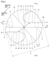
- FIG. 3 is a schematic front view showing the configuration of the drill according to this embodiment.
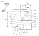
- FIG. 4 is an enlarged schematic front view showing region IV in FIG.
- FIG. 5 is a schematic cross-sectional view taken along line VV in FIG.
- FIG. 6 is a schematic cross-sectional view taken along line VI-VI in FIG.
- FIG. 7 is an enlarged schematic diagram showing region VII in FIG.
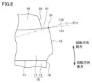
- FIG. 8 is an enlarged schematic diagram showing region VIII in FIG.
- FIG. 9 is an enlarged schematic diagram showing region IX in FIG.
- FIG. 10 is a schematic cross-sectional view showing a state immediately before the drill penetrates the workpiece.
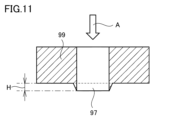
- FIG. 11 is a schematic cross-sectional view showing a state in which a hole has been formed in a workpiece using a drill.
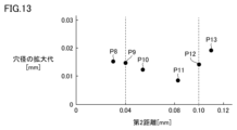
- FIG. 12 is an enlarged schematic front view showing the configuration of the drill according to Sample 1. As shown in FIG. FIG. 13 shows the increase in hole diameter from sample 8 to sample 13.
- FIG. 14 shows the hole position deviations in Samples 8 to 13.
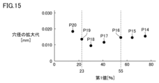
- FIG. 15 shows the increase in hole diameter from sample 14 to sample 20.
- FIG. 16 shows the hole position accuracy in Samples 14 to 20.
- An object of the present disclosure is to provide a drill that can improve the accuracy of hole drilling and the strength of the drill.
- the drill 100 is a drill 100 that rotates around an axis X and includes a first flank 10, a first thinning surface 13, a second flank 20, and a second thinning surface 23.
- the first thinning surface 13 is provided rearward in the rotational direction from the first flank 10.
- the second flank 20 is provided rearward in the rotational direction from the first thinning surface 13.
- the second thinning surface 23 is provided rearward in the rotational direction from the second flank 20.
- the first flank 10 includes a first front flank portion 11 and a first rear flank portion 12.
- the first rear flank portion 12 is continuous with the first front flank portion 11.
- the first rear flank portion 12 is inclined with respect to the first front flank portion 11.
- the first rear flank portion 12 is provided rearward in the rotational direction from the first front flank portion 11.
- the second flank 20 includes a second front flank portion 21 and a second rear flank portion 22.
- the second rear flank portion 22 is continuous with the second front flank portion 21.
- the second rear flank portion 22 is inclined with respect to the second front flank portion 21.
- the second rear flank portion 22 is provided rearward in the rotation direction with respect to the second front flank portion 21.
- the second front flank portion 21 is continuous with each of the first front flank portion 11 and the first rear flank portion 12.
- the second rear flank portion 22 is continuous with the first front flank portion 11.
- the ridgeline between the first front flank portion 11 and the first rear flank portion 12 is defined as a first ridgeline 71.
- the ridgeline between the second front flank portion 21 and the second rear flank portion 22 is defined as a second ridgeline 72.
- the distance E1 between the first ridge line 71 and the second ridge line 72 in a direction perpendicular to the first ridge line 71 is greater than 0 mm and not greater than 0.03 mm.
- the ridge line between the first front flank portion 11 and the second rear flank portion 22 constitutes a first chisel region 41.
- the ridge line between the first rear flank portion 12 and the second front flank portion 21 constitutes a second chisel region 42.
- the ridge line between the first front flank portion 11 and the second front flank portion 21 constitutes a third chisel region 43.
- the third chisel region 43 is continuous with each of the first chisel region 41 and the second chisel region 42.
- the third chisel region 43 is provided at the front end 1.
- the ridgeline between the first thinning surface 13 and the first flank 10 and the ridgeline between the first thinning surface 13 and the second flank 20 form the first thinning ridgeline 15.
- the ridgeline between the second thinning surface 23 and the first flank 10 and the ridgeline between the second thinning surface 23 and the second flank 20 form the second thinning ridgeline 25.
- the shortest distance E2 between the first thinning ridgeline 15 and the second thinning ridgeline 25 in the direction perpendicular to the first ridgeline 71 is 0.04 mm or more and 0.10 mm or less.
- the length L3 of the third chisel region 43 in the axial direction 101 may be 23% or more and 55% or less of the shortest distance E2.
- the cutting edge diameter D of the drill 100 may be 3 mm or less.
- the drill 100 according to (3) above may have a first chip discharge surface 19 and a second chip discharge surface 29.
- the first chip discharge surface 19 may be provided in a spiral shape around the axis X.
- the first chip discharge surface 19 may be continuous with the first flank surface 10.
- the second chip discharge surface 29 may be provided in a spiral shape around the axis X.
- the second chip discharge surface 29 may be continuous with the second flank surface 20.
- Each of the first chip discharge surface 19 and the second chip discharge surface 29 forms a chip discharge groove.
- the length of each of the first chip discharge surface 19 and the second chip discharge surface 29 in the axial direction 101 may be 2 times or more and 10 times or less than the cutting diameter D.
- the ridgeline between the first flank 10 and the first chip discharge surface 19 may form the first cutting edge 51.
- the ridgeline between the second flank 20 and the second chip discharge surface 29 may form the second cutting edge 52.
- the rake angle ⁇ 11 of the first cutting edge 51 in the radial direction of the drill 100 may be -18° or more and -9° or less.
- the rake angle ⁇ 12 of the second cutting edge 52 in the radial direction of the drill 100 may be -18° or more and -9° or less.
- the angle ⁇ 3 between the first ridge 71 and the third chisel region 43 may be greater than the angle ⁇ 1 between the first ridge 71 and the first chisel region 41, and may also be greater than the angle ⁇ 2 between the first ridge 71 and the second chisel region 42.
- the angle ⁇ 3 between the first ridge 71 and the third chisel region 43 when viewed in the axial direction 101 may be 50° or more and 80° or less.
- the angle ⁇ 1 between the first ridge 71 and the first chisel region 41 as viewed in the axial direction 101 may be 40° or more and 60° or less.
- the angle between the first ridge 71 and the second chisel region 42 as viewed in the axial direction 101 may be 40° or more and 60° or less.
- FIG. 1 is a schematic plan view showing the configuration of the drill 100 according to this embodiment.
- the drill 100 according to this embodiment mainly has a front end 1, a rear end 2, a first cutting edge 51, a first chip discharge surface 19, a second chip discharge surface 29, an outer peripheral surface 9, a shank 7, a second flank surface 20, and a second thinning surface 23.
- the drill 100 according to this embodiment is, for example, a drill for metal processing.
- the first chip discharge surface 19 is provided in a spiral shape around the axis X.
- the second chip discharge surface 29 is provided in a spiral shape around the axis X.
- the first chip discharge surface 19 and the second chip discharge surface 29 each form a chip discharge groove.
- the first chip discharge surface 19 forms the first chip discharge groove 93.
- the second chip discharge surface 29 forms the second chip discharge groove 94.
- the outer peripheral surface 9 is continuous with each of the first chip discharge surface 19 and the second chip discharge surface 29.
- the outer peripheral surface 9 has a first outer peripheral surface portion 16 and a second outer peripheral surface portion 26.
- the first outer peripheral surface portion 16 is provided in a spiral shape around the axis X.
- the second outer peripheral surface portion 26 is provided in a spiral shape around the axis X.
- the first cutting edge 51 is provided at a position close to the front end 1 of the drill 100.
- the second thinning surface 23 is continuous with each of the second clearance surface 20, the second outer peripheral surface portion 26, and the first chip discharge surface 19.
- the front end 1 of the drill 100 is the portion that faces the workpiece.
- the rear end 2 of the drill 100 is the portion that faces the tool spindle (not shown) that rotates the drill 100.
- the shank 7 is the portion that is attached to the tool spindle.
- An axis X passes through the front end 1 and the rear end 2.
- the drill 100 rotates around the axis X.
- the direction from the front end 1 to the rear end 2 is referred to as the axial direction 101.
- the axial direction 101 is a direction along the axis X.
- a direction that is perpendicular to the axial direction 101 and toward the axis X is referred to as the radial inner direction.
- a direction that is perpendicular to the axial direction 101 and away from the axis X is referred to as the radial outer direction.
- the length of the first chip discharge surface 19 in the axial direction 101 is defined as a first length L1.
- the first length L1 is, for example, 10 mm.
- the length of the second chip discharge surface 29 in the axial direction 101 is defined as a second length L2.
- the second length L2 is substantially the same as the first length L1.
- FIG. 2 is a schematic perspective view showing the configuration of the drill 100 according to this embodiment.
- the drill 100 according to this embodiment has a first flank 10, a first thinning surface 13, and a second cutting edge 52.
- the first flank 10 is connected to a first chip discharge surface 19 (see FIG. 1) and a first outer peripheral surface portion 16.
- the ridge between the first flank 10 and the first chip discharge surface 19 forms the first cutting edge 51.
- the first chip discharge surface 19 close to the first cutting edge 51 functions as a rake surface.
- the first thinning surface 13 is connected to each of the first flank surface 10, the first outer peripheral surface portion 16, and the second chip discharge surface 29.
- the second flank surface 20 is connected to each of the first flank surface 10, the first thinning surface 13, and the second chip discharge surface 29.
- the ridge between the second flank surface 20 and the second chip discharge surface 29 forms the second cutting edge 52.
- the second chip discharge surface 29 close to the second cutting edge 52 functions as a scooping surface.
- the first flank 10 has a first front flank portion 11 and a first rear flank portion 12.
- the first front flank portion 11 is, for example, planar.
- the first front flank portion 11 is continuous with the first cutting edge 51.
- the ridgeline between the first front flank portion 11 and the first chip discharge surface 19 constitutes the first cutting edge 51.
- the first rear flank portion 12 is, for example, planar.
- the first rear flank portion 12 is continuous with the first front flank portion 11.
- the ridgeline between the first front flank portion 11 and the first rear flank portion 12 is defined as a first ridgeline 71.
- the first ridgeline 71 is, for example, linear.
- the second flank 20 has a second front flank portion 21 and a second rear flank portion 22.
- the second front flank portion 21 is, for example, planar.
- the second front flank portion 21 is connected to the second cutting edge 52.
- the second front flank portion 21 is, for example, planar.
- the second rear flank portion 22 is connected to the second front flank portion 21.
- the ridge line between the second front flank portion 21 and the second rear flank portion 22 is defined as a second ridge line 72.
- the second ridge line 72 is, for example, linear.
- the outer peripheral surface 9 has a first margin surface 18 and a second margin surface 28. From another perspective, the drill 100 has only one pair of margin surfaces.
- the first margin surface 18 is continuous with each of the first outer peripheral surface portion 16 and the first chip discharge surface 19.
- the ridge between the first margin surface 18 and the first chip discharge surface 19 constitutes the first leading edge 17.
- the second margin surface 28 is connected to each of the second outer peripheral surface portion 26, the second clearance surface 20, and the second chip discharge surface 29.
- the ridge between the second margin surface 28 and the second chip discharge surface 29 constitutes the second leading edge 27.
- the first outer peripheral surface portion 16 is connected to each of the first flank surface 10, the first thinning surface 13, and the second chip discharge surface 29.
- the second outer peripheral surface portion 26 is connected to each of the second flank surface 20, the second thinning surface 23, and the first chip discharge surface 19.
- FIG. 3 is a schematic front view showing the configuration of the drill 100 according to this embodiment.
- the schematic front view shown in FIG. 3 shows the configuration of the drill 100 as viewed in the axial direction 101.
- the shank 7 is not shown in FIG. 3.
- the first thinning surface 13 is provided rearward in the direction of rotation from the first flank surface 10.
- the second flank surface 20 is provided rearward in the direction of rotation from the first thinning surface 13.
- the second thinning surface 23 is provided rearward in the direction of rotation from the second flank surface 20.
- the first flank surface 10 is provided rearward in the direction of rotation from the second thinning surface 23.
- the drill 100 may be substantially two-fold symmetric with respect to the axis X.
- the shape of the first flank 10 rotated 180° with respect to the axis X may be substantially the same as the shape of the second flank 20.
- the shape of the first thinning surface 13 rotated 180° with respect to the axis X may be substantially the same as the shape of the second thinning surface 23.
- the second ridge 72 is substantially parallel to the first ridge 71.
- the first front clearance portion 11 is connected to the second thinning surface 23.
- the ridge between the first front clearance portion 11 and the second thinning surface 23 forms the first thinning cutting edge 61.
- the first thinning cutting edge 61 is connected to the first cutting edge 51.
- the first thinning cutting edge 61 is provided radially inward from the first cutting edge 51.
- the first front clearance portion 11 is spaced apart from the first thinning surface 13.
- the first rear flank portion 12 is provided rearward in the rotational direction from the first front flank portion 11.
- the first rear flank portion 12 is continuous with the first thinning surface 13.
- the ridgeline between the first rear flank portion 12 and the first thinning surface 13 is the third ridgeline 73.
- the first rear flank portion 12 is spaced apart from the second thinning surface 23.
- the second front clearance portion 21 is connected to the first thinning surface 13.
- the ridge between the second front clearance portion 21 and the first thinning surface 13 forms the second thinning cutting edge 62.
- the second thinning cutting edge 62 is connected to the second cutting edge 52.
- the second thinning cutting edge 62 is provided radially inward from the second cutting edge 52.
- the second front clearance portion 21 is spaced apart from the second thinning surface 23.
- the second rear flank portion 22 is provided rearward in the rotational direction from the second front flank portion 21.
- the second rear flank portion 22 is connected to the second thinning surface 23.
- the ridge line between the second rear flank portion 22 and the second thinning surface 23 is the fourth ridge line 74.
- the second rear flank portion 22 is spaced apart from the first thinning surface 13.
- the first outer peripheral surface portion 16 is provided radially outward from the first thinning surface 13.
- the second outer peripheral surface portion 26 is provided radially outward from the second thinning surface 23.
- the first cutting edge 51 When viewed in the axial direction 101, the first cutting edge 51 is curved. Specifically, the first cutting edge 51 may be arc-shaped. When viewed in the axial direction 101, the first cutting edge 51 is concave toward the rear in the direction of rotation. When viewed in the axial direction 101, the second cutting edge 52 is curved. Specifically, the second cutting edge 52 may be arc-shaped. When viewed in the axial direction 101, the second cutting edge 52 is concave toward the rear in the direction of rotation.
- the outermost end of the first cutting edge 51 is the first outermost end 91.
- the outermost end of the second cutting edge 52 is the second outermost end 92.
- the first outermost end 91, the second outermost end 92, and the axis X may be aligned in a straight line.
- the distance between the first outermost end 91 and the axis X is substantially the same as the distance between the second outermost end 92 and the axis X.
- the distance between the first outermost end 91 and the second outermost end 92 as viewed in the axial direction 101 is the cutting edge diameter D of the drill 100.
- the cutting edge diameter D is, for example, 3 mm or less.
- the cutting edge diameter D is, for example, 2 mm.
- the upper limit of the cutting edge diameter D is not particularly limited, but may be, for example, 2 mm or less, or 1 mm or less.
- the lower limit of the cutting edge diameter D is not particularly limited, but may be, for example, 0.1 mm or more, or 0.5 mm or more.
- the length of the first chip discharge surface 19 in the axial direction 101 is, for example, 2 to 10 times the blade diameter D.
- the first length L1 may be, for example, 3 to 5 times the blade diameter D.
- the lower limit of the first length L1 is not particularly limited, but may be, for example, 2.5 or more times the blade diameter D, or 4 or more times the blade diameter D.
- the upper limit of the first length L1 is not particularly limited, but may be, for example, 8 or less times the blade diameter D, or 6 or less times the blade diameter D.
- the length of the second chip discharge surface 29 in the axial direction 101 is, for example, 2 to 10 times the blade diameter D.
- the second length L2 may be, for example, 3 to 5 times the blade diameter D.
- the lower limit of the second length L2 is not particularly limited, but may be, for example, 2.5 or more times the blade diameter D, or 4 or more times the blade diameter D.
- the upper limit of the second length L2 is not particularly limited, but may be, for example, 8 or less times the blade diameter D, or 6 or less times the blade diameter D.
- the ridge between the first chip discharge surface 19 and the second thinning surface 23 is the fifth ridge 75.
- the fifth ridge 75 is recessed forward in the direction of rotation.
- the fifth ridge 75 overlaps the first thinning cutting edge 61 at a first point 121 on the first thinning cutting edge 61.
- the fifth ridge 75 extends from the first point 121 forward in the direction of rotation relative to the first thinning cutting edge 61.
- a straight line passing through the first point 121 and parallel to the first ridge 71 is the first virtual line 111.
- the first cutting edge 51 is provided forward in the direction of rotation relative to the first virtual line 111.
- the ridge between the second chip discharge surface 29 and the first thinning surface 13 is defined as the sixth ridge 76.
- the sixth ridge 76 When viewed in the axial direction 101, the sixth ridge 76 is concave forward in the direction of rotation. When viewed in the axial direction 101, the sixth ridge 76 overlaps the second thinning cutting edge 62 at a second point 122 on the second thinning cutting edge 62. From another perspective, when viewed in the axial direction 101, the sixth ridge 76 extends from the second point 122 forward in the direction of rotation relative to the second thinning cutting edge 62. When viewed in the axial direction 101, a straight line passing through the second point 122 and parallel to the first ridge 71 is defined as the second virtual line 112.
- the second cutting edge 52 When viewed in the axial direction 101, the second cutting edge 52 is provided forward in the direction of rotation relative to the second virtual line 112. As shown in FIG. 3, the direction toward the inside of the radial direction and parallel to the first ridge line 71 when viewed in the axial direction 101 is defined as the side view direction 102.
- FIG. 4 is an enlarged schematic front view showing region IV in FIG. 3. As shown in FIG. 4, the second front clearance portion 21 is continuous with each of the first front clearance portion 11 and the first rear clearance portion 12. The second rear clearance portion 22 is continuous with the first front clearance portion 11. The second rear clearance portion 22 is spaced apart from the first rear clearance portion 12.
- the ridgeline between the first front flank portion 11 and the second rear flank portion 22 constitutes a first chisel region 41.
- the first chisel region 41 is, for example, linear.
- the ridgeline between the first rear flank portion 12 and the second front flank portion 21 constitutes a second chisel region 42.
- the second chisel region 42 is, for example, linear.
- the second chisel region 42 is spaced apart from the first chisel region 41.
- the ridge between the first front flank portion 11 and the second front flank portion 21 constitutes a third chisel region 43.
- the third chisel region 43 may intersect with the axis X.
- the third chisel region 43 has a first end 81 and a second end 82. At the first end 81, the third chisel region 43 is continuous with each of the first chisel region 41 and the second ridge 72.
- the second end 82 is opposite the first end 81.
- the third chisel region 43 is continuous with each of the second chisel region 42 and the first ridge 71.
- the third chisel region 43 is provided radially inward with respect to the first chisel region 41.
- the third chisel region 43 is provided radially inward with respect to the second chisel region 42.
- a straight line extending in the direction in which the second ridge line 72 extends is defined as a third virtual line 113.
- the third virtual line 113 is located forward of the first ridge line 71 in the rotational direction.
- a distance between the first ridge line 71 and the second ridge line 72 in a direction perpendicular to the first ridge line 71 is defined as a first distance E1.
- the first distance E1 is the distance between the third virtual line 113 and the first ridge line 71 when viewed in the axial direction 101.
- the first distance E1 is greater than 0 mm and equal to or less than 0.03 mm.
- the lower limit of the first distance E1 is not particularly limited, but may be, for example, 0.005 mm or more, or 0.01 mm or more.
- the upper limit of the first distance E1 is not particularly limited, but may be, for example, 0.027 mm or less, or 0.023 mm or less.
- the ridgeline between the first thinning surface 13 and the first flank surface 10 (third ridgeline 73) and the ridgeline between the first thinning surface 13 and the second flank surface 20 (second thinning cutting edge 62) form the first thinning ridgeline 15.
- the first thinning ridgeline 15 is connected to the second chisel region 42.
- the first thinning ridgeline 15 is recessed radially inward.
- a point located on the first thinning ridgeline 15 and closest to the axis X in a direction perpendicular to the first ridgeline 71 when viewed in the axial direction 101 is defined as the third point 123.
- the third point 123 is located, for example, on the third ridgeline 73.
- the ridgeline between the second thinning surface 23 and the first flank surface 10 (first thinning cutting edge 61) and the ridgeline between the second thinning surface 23 and the second flank surface 20 (fourth ridgeline 74) form the second thinning ridgeline 25.
- the second thinning ridgeline 25 is connected to the first chisel region 41. When viewed in the axial direction 101, the second thinning ridgeline 25 is recessed radially inward.
- a point located on the second thinning ridgeline 25 and closest to the axis X in a direction perpendicular to the first ridgeline 71 when viewed in the axial direction 101 is defined as the fourth point 124.
- the fourth point 124 is located, for example, on the fourth ridgeline 74.
- the second distance E2 is the shortest distance between the first thinning ridge 15 and the second thinning ridge 25 in a direction perpendicular to the first ridge 71.
- the second distance E2 is 0.04 mm or more and 0.10 mm or less.
- the lower limit of the second distance E2 is not particularly limited, but may be, for example, 0.05 mm or more, or 0.053 mm or more.
- the upper limit of the second distance E2 is not particularly limited, but may be, for example, 0.09 mm or less, or 0.085 mm or less.
- the second distance E2 is greater than the first distance E1.
- the length of the third chisel region 43 when viewed in the axial direction 101 is the third length L3.
- the third length L3 is the distance between the first end 81 and the second end 82 when viewed in the axial direction 101.
- the third length L3 is 23% to 55% of the second distance E2.
- the percentage (first value) of the value obtained by dividing the third length L3 by the second distance E2 is 23% to 55%.
- the lower limit of the first value is not particularly limited, but may be, for example, 28% or more, or 35% or more.
- the upper limit of the first value is not particularly limited, but may be, for example, 50% or less, or 45% or less.
- the fourth imaginary line 114 When viewed in the axial direction 101, a straight line that is parallel to the first ridge 71 and intersects with the first chisel region 41 is defined as the fourth imaginary line 114.
- the acute angle between the fourth imaginary line 114 and the first chisel region 41 is defined as the first angle ⁇ 1.
- the first angle ⁇ 1 is the angle between the first ridge 71 and the first chisel region 41 when viewed in the axial direction 101.
- the first angle ⁇ 1 is, for example, 40° or more and 60° or less.
- the lower limit of the first angle ⁇ 1 is not particularly limited, but may be, for example, 43° or more, or 47° or more.
- the upper limit of the first angle ⁇ 1 is not particularly limited, but may be, for example, 57° or less, or 53° or less.
- a straight line that is parallel to the first ridge 71 and intersects with the second chisel region 42 is defined as the fifth imaginary line 115.
- the angle that is an acute angle between the fifth imaginary line 115 and the second chisel region 42 is defined as the second angle ⁇ 2.
- the second angle ⁇ 2 is the angle between the first ridge 71 and the second chisel region 42 when viewed in the axial direction 101.
- the second angle ⁇ 2 is, for example, 40° or more and 60° or less.
- the lower limit of the second angle ⁇ 2 is not particularly limited, but may be, for example, 43° or more, or 47° or more.
- the upper limit of the second angle ⁇ 2 is not particularly limited, but may be, for example, 57° or less, or 53° or less.
- the angle between the first ridge 71 and the third chisel region 43 is a third angle ⁇ 3.
- the third angle ⁇ 3 is an acute angle.
- the third angle ⁇ 3 is greater than the first angle ⁇ 1.
- the first chisel region 41 is inclined backward in the rotational direction relative to the third chisel region 43.
- the third angle ⁇ 3 is greater than the second angle ⁇ 2.
- the second chisel region 42 is inclined backward in the rotational direction relative to the third chisel region 43.
- the third angle ⁇ 3 is, for example, 50° or more and 80° or less.
- the lower limit of the third angle ⁇ 3 is not particularly limited, but may be, for example, 55° or more, or 60° or more.
- the upper limit of the third angle ⁇ 3 is not particularly limited, but may be, for example, 75° or less, or 70° or less.
- FIG. 5 is a schematic cross-sectional view taken along line V-V in FIG. 4.
- the cross-section shown in FIG. 5 is a cross-section that includes the axis X and is parallel to the first ridge 71 when viewed in the axial direction 101.
- a cross-section that includes the axis X and is parallel to the first ridge 71 when viewed in the axial direction 101 is referred to as a first cross-section CS1.
- the first front clearance portion 11 is, for example, linear.
- the straight line extending in the direction in which the first front clearance portion 11 extends is referred to as a sixth virtual line 116.
- the second front clearance portion 21 is, for example, linear.
- the straight line extending in the direction in which the second front clearance portion 21 extends is referred to as a seventh virtual line 117.
- the angle that is an obtuse angle is set as the fourth angle ⁇ 4.
- the fourth angle ⁇ 4 is the angle between the first front flank portion 11 and the second front flank portion 21.
- the fourth angle ⁇ 4 is the tip angle of the drill 100.
- the fourth angle ⁇ 4 is, for example, 140°.
- the fourth angle ⁇ 4 may be 120° or more and 160° or less.
- the axis X substantially bisects the angle between the first front flank portion 11 and the second front flank portion 21.
- FIG. 6 is a schematic cross-sectional view taken along line VI-VI in FIG. 3.
- the cross-section shown in FIG. 6 is parallel to axis X and intersects with first ridge 71.
- the cross-section shown in FIG. 6 is perpendicular to first ridge 71.
- the schematic cross-sectional view shown in FIG. 6 shows the configuration of drill 100 as viewed in side view direction 102 (see FIG. 3).
- the cross-section parallel to axis X and intersecting with first ridge 71 is referred to as second cross-section CS2.
- the first rear clearance portion 12 is inclined relative to the first front clearance portion 11. Specifically, in the second cross section CS2, the first rear clearance portion 12 is inclined in the axial direction 101 relative to the first front clearance portion 11. Similarly, the second rear clearance portion 22 (see FIG. 3) is inclined relative to the second front clearance portion 21 (see FIG. 3).
- each of the first front clearance portion 11 and the first rear clearance portion 12 may be straight.
- each of the second front clearance portion 21 and the second front clearance portion 21 may be straight.
- FIG. 7 is an enlarged schematic diagram showing region VII in FIG. 6.
- the third chisel region 43 is provided at the front end 1 of the drill 100.
- the third chisel region 43 is substantially perpendicular to the axis X.
- the first chisel region 41 is inclined in the axial direction 101 relative to the third chisel region 43.
- the inclination angle of the first chisel region 41 relative to the third chisel region 43 is set to a fifth angle ⁇ 5.
- the fifth angle ⁇ 5 is, for example, greater than or equal to 3° and less than or equal to 15°.
- the second chisel region 42 When viewed in the side view direction 102, the second chisel region 42 is inclined in the axial direction 101 relative to the third chisel region 43.
- the inclination angle of the second chisel region 42 relative to the third chisel region 43 is set to a sixth angle ⁇ 6.
- the sixth angle ⁇ 6 is, for example, greater than or equal to 3° and less than or equal to 15°.
- FIG. 8 is an enlarged schematic diagram showing region VIII in FIG. 3. As shown in FIG. 8, when viewed in the axial direction 101, the tangent to the first cutting edge 51 at the first outermost end 91 is the first tangent 131. When viewed in the axial direction 101, the straight line passing through the first outermost end 91 and the axis X (see FIG. 3) is the eighth virtual line 118.
- the first tangent 131 When viewed in the axial direction 101, the first tangent 131 is inclined backward in the rotational direction with respect to the eighth imaginary line 118. When viewed in the axial direction 101, the acute angle between the first tangent 131 and the eighth imaginary line 118 is set to the first rake angle ⁇ 11. From another perspective, at the outermost end 91 of the first cutting edge 51, the rake angle of the first cutting edge 51 in the radial direction of the drill 100 is set to the first rake angle ⁇ 11. The first rake angle ⁇ 11 is negative.
- a "positive" rake angle of the cutting edge in the radial direction of the drill 100 at the outermost peripheral end of the cutting edge means that, when viewed in the axial direction 101, the tangent to the cutting edge at the outermost peripheral end is inclined forward in the direction of rotation of the drill 100 relative to a straight line passing through the axis X and the outermost peripheral end.
- a "negative" rake angle of the cutting edge in the radial direction of the drill 100 at the outermost peripheral end of the cutting edge means that, when viewed in the axial direction 101, the tangent to the cutting edge at the outermost peripheral end is inclined backward in the direction of rotation of the drill 100 relative to a straight line passing through the axis X and the outermost peripheral end.
- the first rake angle ⁇ 11 is, for example, -18° or more and -9° or less.
- the first rake angle ⁇ 11 may be, for example, -14° or more and -10° or less.
- the lower limit of the first rake angle ⁇ 11 is not particularly limited, but may be, for example, -16° or more, or -13° or more.
- the upper limit of the first rake angle ⁇ 11 is not particularly limited, but may be, for example, -9.5° or less, or -11° or less.
- FIG. 9 is an enlarged schematic diagram showing region IX in FIG. 3.
- the tangent to the second cutting edge 52 at the second outermost end 92 is the second tangent 132.
- the straight line passing through the second outermost end 92 and the axis X is the ninth imaginary line 119.
- the ninth imaginary line 119 may overlap the eighth imaginary line 118 (see FIG. 8).
- the second tangent 132 When viewed in the axial direction 101, the second tangent 132 is inclined backward in the rotational direction with respect to the ninth imaginary line 119. When viewed in the axial direction 101, the acute angle between the second tangent 132 and the ninth imaginary line 119 is set to the second rake angle ⁇ 12. From another perspective, at the outermost end 92 of the second cutting edge 52, the rake angle of the second cutting edge 52 in the radial direction of the drill 100 is set to the second rake angle ⁇ 12. The second rake angle ⁇ 12 is negative. The second rake angle ⁇ 12 is substantially the same as the first rake angle ⁇ 11.
- the second rake angle ⁇ 12 is, for example, -18° or more and -9° or less.
- the second rake angle ⁇ 12 may be, for example, -14° or more and -10° or less.
- the lower limit of the second rake angle ⁇ 12 is not particularly limited, but may be, for example, -16° or more, or -13° or more.
- the upper limit of the second rake angle ⁇ 12 is not particularly limited, but may be, for example, -9.5° or less, or -11° or less.
- the drill 100 according to the present embodiment has a first chisel region 41, a second chisel region 42, and a third chisel region 43.
- the third chisel region 43 is continuous with each of the first chisel region 41 and the second chisel region 42.
- the third chisel region 43 is provided at the front end 1. Therefore, when a workpiece is machined using the drill 100, the third chisel region 43 comes into contact with the workpiece first.
- the distance (first distance E1) between the first ridge line 71 and the second ridge line 72 is 0.03 mm or less.
- the shortest distance (second distance E2) between the first thinning ridge line 15 and the second thinning ridge line 25 in a direction perpendicular to the first ridge line 71 is 0.10 mm or less.
- the length of the third chisel region 43 can be prevented from becoming excessively long. This prevents the contact area between the drill 100 and the workpiece from becoming excessively large immediately after the start of hole drilling using the drill 100. This improves the bite of the drill 100. This prevents the drill 100 from shaking during hole drilling. This improves the hole diameter enlargement and hole position accuracy of the hole drilled using the drill 100. As a result, the accuracy of hole drilling can be improved.
- the second distance E2 By setting the second distance E2 to 0.10 mm or less, the length of each of the first chisel region 41 and the second chisel region 42 can be prevented from becoming excessively long.
- the first distance E1 is greater than 0 mm.
- the second distance E2 is 0.04 mm or greater.
- the length of the third chisel region 43 may be 23% or more and 55% or less of the second distance E2. This can improve the hole position accuracy of the hole formed using the drill 100.
- the cutting diameter D of the drill 100 may be 3 mm or less.
- an oil-based coolant is often supplied by external oil supply.
- the temperature of the drill 100 is likely to be high compared to when the coolant is supplied by internal oil supply. Therefore, in a drill 100 with a small cutting diameter D, the number of margin surfaces is often two (one pair) in order to reduce friction between the drill 100 and the workpiece. In this case, the drill 100 is more likely to vibrate compared to when the number of margin surfaces is four (two pairs) or more. As a result, the accuracy of hole machining is reduced. According to the drill 100 of this embodiment, even when the cutting diameter D is 3 mm or less, the deterioration of the accuracy of hole machining can be suppressed.
- FIG. 10 is a schematic cross-sectional view showing a state immediately before the drill 100 penetrates the workpiece 99. As shown in FIG. 10, a remaining portion 98 of the workpiece 99 is formed immediately before the drill 100 penetrates the workpiece 99 during hole drilling. The remaining portion 98 is a portion that is not cut by the cutting edge of the drill 100.
- FIG. 11 is a schematic cross-sectional view showing a state in which a hole is formed in the workpiece 99 using the drill 100. As shown in FIG. 10 and FIG. 11, when the drill 100 penetrates the workpiece 99, the remaining portion 98 receives a load in a direction along the machining direction A of the drill 100. The load causes the remaining portion 98 to plastically deform.
- a burr 97 is formed in the workpiece 99.
- the distance between the point on the burr 97 that is farthest from the surface of the workpiece 99 and the surface of the workpiece 99 is set to the height H of the burr 97. It is preferable that the height H of the burr 97 is low.
- the rake angle (first rake angle ⁇ 11) of the first cutting edge 51 in the radial direction of the drill 100 may be -18° or more and -9° or less.
- the rake angle (second rake angle ⁇ 12) of the second cutting edge 52 in the radial direction of the drill 100 may be -18° or more and -9° or less.
- each of the first rake angle ⁇ 11 and the second rake angle ⁇ 12 is set to -9° or less, it is possible to prevent a decrease in the strength of the cutting edge around the outermost end. This makes it possible to prevent a decrease in sharpness due to chipping of the cutting edge even after drilling multiple holes with the drill 100. As a result, it is possible to prevent the burr height H from increasing even after drilling multiple holes with the drill 100.
- Example preparation First, the drills 100 according to Sample 1 and Sample 2 were prepared.
- the drill 100 according to Sample 1 was used as a comparative example.
- the drill 100 according to Sample 2 was used as an example.
- FIG. 12 is an enlarged schematic front view showing the configuration of the drill 100 of Sample 1.
- the enlarged schematic front view shown in FIG. 12 corresponds to the enlarged schematic front view shown in FIG. 4.
- the drill 100 of Sample 1 did not have the first chisel region 41 and the second chisel region 42.
- the percentage (first value) of the length of the third chisel region 43 (third length L3) divided by the second distance E2 was set to 113%.
- the configuration of the drill 100 in sample 2 was the same as the configuration of the drill 100 in this embodiment (see FIG. 4).
- the first distance E1 was set to 0.02 mm.
- the first value was set to 32%.
- the cutting diameter D was set to 2 mm.
- the length of each of the first chip discharge surface 19 and the second chip discharge surface 29 was set to 5 times the cutting diameter D.
- the second distance E2 was set to 0.07 mm.
- Each of the first rake angle ⁇ 11 and the second rake angle ⁇ 12 (hereinafter also simply referred to as the rake angle) was set to -12°.
- the hole diameter enlargement allowance and hole position accuracy were evaluated using the drills 100 according to Sample 1 and Sample 2. Specifically, holes were formed in a workpiece using the drills 100 according to Sample 1 and Sample 2. The diameter of the formed hole was measured. The value obtained by subtracting the cutting edge diameter of the drill 100 from the diameter of the formed hole was determined as the hole diameter enlargement allowance. The value twice the distance between the target position of the center of the hole and the position of the center of the formed hole was determined as the hole position accuracy.
- the workpiece material was SCM415.
- SCM415 is an alloy steel specified in JIS (Japanese Industrial Standards) G 4053:2016.
- the hole depth was 6 mm.
- the cutting speed was 38 m/min.
- the feed rate was 0.04 mm/rev.
- Table 1 shows the hole diameter enlargement and hole position accuracy for Sample 1 and Sample 2. As shown in Table 1, the hole diameter enlargement in Sample 2 was smaller than the hole diameter enlargement in Sample 1. The hole position accuracy in Sample 2 was smaller than the hole position accuracy in Sample 1.
- Example preparation Next, the drills 100 according to Samples 3 to 7 were prepared.
- the drills 100 according to Samples 3, 6, and 7 were used as comparative examples.
- the drills 100 according to Samples 4 and 5 were used as examples.
- the first distance E1 was changed in the drills 100 relating to samples 3 to 7.
- the first distance E1 was set to 0 mm or more and 0.10 mm or less.
- the first value was set to 0% or more and 113% or less.
- the cutting edge diameter D was set to 2 mm.
- the length of each of the first chip discharge surface 19 and the second chip discharge surface 29 was set to 5 times the cutting edge diameter D.
- the second distance E2 was set to 0.08 mm.
- the rake angle was set to -12°.
- biting shape was evaluated using the drills 100 according to Samples 3 to 7. Specifically, holes were formed in the workpiece using the drills 100 according to Samples 3 to 7. The depth of the holes was about 0.3 mm. The shape of the trace of the contact of the drill 100 (biting shape) was confirmed at the portion of the workpiece where the drill 100 contacted. If the biting ability of the drill 100 is good, the biting shape will be circular.
- the workpiece was SCM415.
- the cutting speed was 38 m/min.
- the feed rate was 0.04 mm/revolution.
- the hole diameter enlargement and hole position accuracy were evaluated using the drills 100 relating to samples 3 to 7. Specifically, the hole diameter enlargement and hole position accuracy were each measured using the evaluation method described above.
- the number of holes machined for each of the drills 100 relating to samples 3 to 7 was evaluated. Specifically, multiple holes were formed in the workpiece using the drills 100 relating to samples 3 to 7. The maximum number of holes was 600. In cases where damage to the drill 100 was confirmed, the number of holes formed before damage was confirmed was measured as the number of holes machined. In cases where damage to the drill 100 was not confirmed, the number of holes machined was 600. In the evaluation of the number of holes machined, the workpiece was SCM415. The hole depth was 6 mm. The cutting speed was 38 m/min. The feed rate was 0.04 mm/revolution.
- Table 2 shows the bite shape, hole diameter enlargement, hole position, and number of machined holes for samples 3 to 7. As shown in Table 2, when the first distance E1 was 0.03 mm or less (samples 3 to 5), the bite shape was circular. When the first distance E1 was 0.05 mm or more (samples 6 and 7), the bite shape was irregular. Specifically, the bite shape was triangular.
- the hole diameter enlargement was 0.018 mm or less.
- the hole position deviation was 0.016 mm or less.
- the first distance E1 was 0.05 mm or more (samples 6 and 7)
- the hole diameter enlargement was 0.028 mm or more.
- the hole position deviation was 0.021 mm or more.
- the number of machined holes was 126. Specifically, in sample 3, defects were confirmed around the front end 1 of the drill 100. When the first distance E1 was greater than 0 mm (samples 4 to 7), the number of machined holes was 600. In other words, no damage to the drill 100 was confirmed in samples 4 to 7.
- the drill 100 according to the embodiment can improve the biting ability, reduce the hole diameter enlargement and hole position tolerance, and improve the strength of the drill 100, compared to the drill 100 according to the comparative example.
- Example preparation Next, the drills 100 according to Samples 8 to 13 were prepared. The drills 100 according to Samples 8 and 13 were used as comparative examples. The drills 100 according to Samples 9 to 12 were used as examples.
- the second distance E2 was changed in the drills 100 relating to samples 8 to 13.
- the second distance E2 was set to 0.030 mm or more and 0.110 mm or less.
- the first value was set to 20% or more and 74% or less.
- the cutting edge diameter D was set to 2 mm.
- the length of each of the first chip discharge surface 19 and the second chip discharge surface 29 was set to 5 times the cutting edge diameter D.
- the first distance E1 was set to 0.02 mm.
- the rake angle was set to -12°.
- Table 3 shows the hole diameter enlargement, hole position, and number of machined holes for samples 8 to 13.
- Figure 13 shows the hole diameter enlargement for samples 8 to 13.
- the horizontal axis shows the second distance E2.
- the vertical axis shows the hole diameter enlargement.
- the point indicated by P8 shows the hole diameter enlargement for sample 8.
- the points indicated by P9 to P13 show the hole diameter enlargement for samples 9 to 13.
- FIG. 14 shows the hole position degree in samples 8 to 13.
- the horizontal axis shows the second distance E2.
- the vertical axis shows the hole position degree.
- the point indicated by P8 shows the hole position degree in sample 8.
- the points indicated by P9 to P13 show the hole position degree in samples 9 to 13.
- the drill 100 according to the embodiment can reduce the hole diameter enlargement and hole position deviation, and can improve the strength of the drill 100, compared to the drill 100 according to the comparative example.
- Example preparation Next, the drills 100 according to Samples 14 to 20 were prepared. The drills 100 according to Samples 14, 15, and 20 were used as comparative examples. The drills 100 according to Samples 16 to 19 were used as examples.
- the value (first value) obtained by dividing the length of the third chisel region 43 by the second distance E2 was changed.
- the first value was set to be 15% or more and 75% or less.
- the second distance E2 was set to be 0.030 mm or more and 0.150 mm or less.
- the cutting edge diameter D was set to 2 mm.
- the length of each of the first chip discharge surface 19 and the second chip discharge surface 29 was set to 5 times the cutting edge diameter D.
- the first distance E1 was set to 0.02 mm.
- the rake angle was set to -12°.
- Table 4 shows the hole diameter enlargement, hole position, and number of machined holes for samples 14 to 20.
- Figure 15 shows the hole diameter enlargement for samples 14 to 20.
- the horizontal axis shows the first value.
- the vertical axis shows the hole diameter enlargement.
- the point indicated by P14 shows the hole diameter enlargement for sample 14.
- the points indicated by P15 to P20 show the hole diameter enlargement for samples 15 to 20.
- Figure 16 shows the hole position degree in samples 14 to 20.
- the horizontal axis shows the first value.
- the vertical axis shows the hole position degree.
- the point indicated by P14 shows the hole position degree in sample 14.
- each of the points indicated by P15 to P20 shows the hole position degree in samples 15 to 20.
- the hole diameter enlargement when the first value was 23% or more and 65% or less was smaller than the hole diameter enlargement when the first value was less than 23% or more than 65% (samples 14 and sample 20).
- the hole position degree when the first value was 23% or more and 55% or less was smaller than the hole position degree when the first value was less than 23% or more than 55% (samples 14, sample 15, and sample 20).
- Example preparation Next, the drills 100 according to Samples 21 to 27 were prepared.
- the drills 100 according to Samples 21 and 27 were used as comparative examples.
- the drills 100 according to Samples 22 to 26 were used as examples.
- the rake angle was changed in the drills 100 relating to samples 21 to 27.
- the rake angle was set to -24° or more and -6° or less.
- the cutting edge diameter D was set to 2 mm.
- the length of each of the first chip discharge surface 19 and the second chip discharge surface 29 was set to 5 times the cutting edge diameter D.
- the first distance E1 was set to 0.02 mm.
- the second distance E2 was set to 0.08 mm.
- the first value was set to 28%.
- the burr height H (see FIG. 11 ) was measured after drilling 300 holes using the drills 100 according to Samples 21 to 27. Specifically, the distance between the point on the burr 97 farthest from the surface of the workpiece 99 in the machining direction of the drill 100 and the surface of the workpiece 99 was measured as the burr height H.
- the workpiece was SCM415.
- the hole depth was 6 mm.
- the cutting speed was 38 m/min.
- the feed rate was 0.04 mm/rev.
- the drills 100 relating to samples 21 to 27 were used to evaluate the hole diameter enlargement, hole position accuracy, and number of holes machined. Specifically, the hole diameter enlargement, hole position accuracy, and number of holes machined were measured using the evaluation method described above.
- Table 5 shows the hole diameter enlargement, hole position accuracy, burr height H, and number of drilled holes for the drill 100 of samples 21 to 27.
- the burr height H when the rake angle was -18° or more and -9° or less was smaller than the burr height H when the rake angle was less than -18° or greater than -9° (samples 21 and 27).
Landscapes
- Engineering & Computer Science (AREA)
- Mechanical Engineering (AREA)
- Drilling Tools (AREA)
Priority Applications (5)
| Application Number | Priority Date | Filing Date | Title |
|---|---|---|---|
| CN202380072380.7A CN120076889A (zh) | 2023-01-12 | 2023-01-12 | 钻头 |
| JP2023543351A JP7456565B1 (ja) | 2023-01-12 | 2023-01-12 | ドリル |
| US18/288,383 US20250083237A1 (en) | 2023-01-12 | 2023-01-12 | Drill |
| PCT/JP2023/000637 WO2024150374A1 (ja) | 2023-01-12 | 2023-01-12 | ドリル |
| EP23915996.5A EP4650087A4 (en) | 2023-01-12 | 2023-01-12 | Drill |
Applications Claiming Priority (1)
| Application Number | Priority Date | Filing Date | Title |
|---|---|---|---|
| PCT/JP2023/000637 WO2024150374A1 (ja) | 2023-01-12 | 2023-01-12 | ドリル |
Publications (1)
| Publication Number | Publication Date |
|---|---|
| WO2024150374A1 true WO2024150374A1 (ja) | 2024-07-18 |
Family
ID=90366997
Family Applications (1)
| Application Number | Title | Priority Date | Filing Date |
|---|---|---|---|
| PCT/JP2023/000637 Ceased WO2024150374A1 (ja) | 2023-01-12 | 2023-01-12 | ドリル |
Country Status (5)
| Country | Link |
|---|---|
| US (1) | US20250083237A1 (https=) |
| EP (1) | EP4650087A4 (https=) |
| JP (1) | JP7456565B1 (https=) |
| CN (1) | CN120076889A (https=) |
| WO (1) | WO2024150374A1 (https=) |
Citations (8)
| Publication number | Priority date | Publication date | Assignee | Title |
|---|---|---|---|---|
| JPS60114407A (ja) * | 1983-11-24 | 1985-06-20 | Sumitomo Electric Ind Ltd | ドリル |
| US4759667A (en) * | 1985-11-08 | 1988-07-26 | American Telephone And Telegraph Company, At&T Technologies, Inc. | Twist drill for drilling printed circuit board laminates and having an drill point geometry |
| JPH0740015U (ja) * | 1993-12-24 | 1995-07-18 | 東芝タンガロイ株式会社 | ツイストドリル |
| JP2000271811A (ja) * | 1999-03-23 | 2000-10-03 | Toshiba Tungaloy Co Ltd | ツイストドリル |
| JP2003266225A (ja) * | 2002-03-13 | 2003-09-24 | Mitsubishi Materials Corp | 穴明け工具 |
| JP2009023055A (ja) * | 2007-07-20 | 2009-02-05 | Toyota Motor Corp | ドリル |
| WO2017179689A1 (ja) | 2016-04-15 | 2017-10-19 | 三菱日立ツール株式会社 | 小径ドリル |
| JP2021003773A (ja) * | 2019-06-26 | 2021-01-14 | 株式会社ビック・ツール | 炭素繊維複合材用ドリル |
Family Cites Families (13)
| Publication number | Priority date | Publication date | Assignee | Title |
|---|---|---|---|---|
| JPH03117508A (ja) * | 1989-09-29 | 1991-05-20 | Kobe Steel Ltd | ドリル |
| JP2538864Y2 (ja) * | 1991-09-26 | 1997-06-18 | オーエスジー株式会社 | 難削材用硬質膜被覆ドリル |
| JP4120185B2 (ja) * | 2001-07-10 | 2008-07-16 | 三菱マテリアル株式会社 | ドリル |
| JP2003025127A (ja) * | 2001-07-10 | 2003-01-29 | Mitsubishi Materials Corp | ドリル |
| JP2003266223A (ja) * | 2002-03-18 | 2003-09-24 | Osg Corp | 深穴加工方法および深穴加工用ドリル |
| WO2009001681A1 (ja) * | 2007-06-22 | 2008-12-31 | Hitachi Tool Engineering, Ltd. | 深穴加工用小径ドリルおよび微細深穴加工方法 |
| DE102010006797B4 (de) * | 2010-02-04 | 2011-12-22 | Kennametal Inc. | Bohrwerkzeug |
| US9539652B2 (en) * | 2010-04-30 | 2017-01-10 | Kennametal Inc. | Rotary cutting tool having PCD cutting tip |
| TWI446980B (zh) * | 2010-11-26 | 2014-08-01 | Tungaloy Corp | Small diameter drill |
| JP6428406B2 (ja) * | 2015-03-18 | 2018-11-28 | 三菱マテリアル株式会社 | ドリル |
| JP6834810B2 (ja) * | 2017-06-28 | 2021-02-24 | 株式会社Moldino | ドリル |
| WO2019054289A1 (ja) * | 2017-09-14 | 2019-03-21 | 三菱日立ツール株式会社 | 小径ドリルおよび小径ドリルの製造方法 |
| EP3808479B1 (en) * | 2019-08-23 | 2022-06-22 | Nishiken Inc. | Single-edge drill for forming a deep hole |
-
2023
- 2023-01-12 US US18/288,383 patent/US20250083237A1/en active Pending
- 2023-01-12 JP JP2023543351A patent/JP7456565B1/ja active Active
- 2023-01-12 EP EP23915996.5A patent/EP4650087A4/en active Pending
- 2023-01-12 WO PCT/JP2023/000637 patent/WO2024150374A1/ja not_active Ceased
- 2023-01-12 CN CN202380072380.7A patent/CN120076889A/zh active Pending
Patent Citations (8)
| Publication number | Priority date | Publication date | Assignee | Title |
|---|---|---|---|---|
| JPS60114407A (ja) * | 1983-11-24 | 1985-06-20 | Sumitomo Electric Ind Ltd | ドリル |
| US4759667A (en) * | 1985-11-08 | 1988-07-26 | American Telephone And Telegraph Company, At&T Technologies, Inc. | Twist drill for drilling printed circuit board laminates and having an drill point geometry |
| JPH0740015U (ja) * | 1993-12-24 | 1995-07-18 | 東芝タンガロイ株式会社 | ツイストドリル |
| JP2000271811A (ja) * | 1999-03-23 | 2000-10-03 | Toshiba Tungaloy Co Ltd | ツイストドリル |
| JP2003266225A (ja) * | 2002-03-13 | 2003-09-24 | Mitsubishi Materials Corp | 穴明け工具 |
| JP2009023055A (ja) * | 2007-07-20 | 2009-02-05 | Toyota Motor Corp | ドリル |
| WO2017179689A1 (ja) | 2016-04-15 | 2017-10-19 | 三菱日立ツール株式会社 | 小径ドリル |
| JP2021003773A (ja) * | 2019-06-26 | 2021-01-14 | 株式会社ビック・ツール | 炭素繊維複合材用ドリル |
Non-Patent Citations (1)
| Title |
|---|
| See also references of EP4650087A1 |
Also Published As
| Publication number | Publication date |
|---|---|
| JPWO2024150374A1 (https=) | 2024-07-18 |
| CN120076889A (zh) | 2025-05-30 |
| EP4650087A4 (en) | 2026-03-11 |
| EP4650087A1 (en) | 2025-11-19 |
| US20250083237A1 (en) | 2025-03-13 |
| JP7456565B1 (ja) | 2024-03-27 |
Similar Documents
| Publication | Publication Date | Title |
|---|---|---|
| US6923602B2 (en) | Drill having construction for reducing thrust load in drilling operation, and method of manufacturing the drill | |
| JPWO2019073752A1 (ja) | 回転切削工具 | |
| KR20190096399A (ko) | 볼 엔드 밀 | |
| WO2020213482A1 (ja) | ドリル | |
| US20240181542A1 (en) | Drill | |
| JPH03245914A (ja) | 穴明け工具 | |
| JP7456565B1 (ja) | ドリル | |
| JP7138927B2 (ja) | ドリル | |
| JP5691424B2 (ja) | ドリル | |
| JP2002205212A (ja) | ドリル | |
| JP7510647B2 (ja) | 回転工具 | |
| JP2017087342A (ja) | ツイストドリル | |
| JP7400311B2 (ja) | ドリル | |
| JP7164084B2 (ja) | ドリル | |
| US20240375191A1 (en) | Drill | |
| JP6902284B2 (ja) | 切削工具 | |
| JP2022159631A (ja) | 切削工具 | |
| JP7714763B2 (ja) | リーマ | |
| JP4725369B2 (ja) | ドリル | |
| JP5052399B2 (ja) | めねじの加工方法 | |
| JPH02292109A (ja) | エンドミル | |
| JP7596716B2 (ja) | ドリル | |
| JP2014079814A (ja) | 穴加工工具 | |
| JP3105301B2 (ja) | スローアウェイ式ドリル | |
| JPH0890323A (ja) | ドリル |
Legal Events
| Date | Code | Title | Description |
|---|---|---|---|
| WWE | Wipo information: entry into national phase |
Ref document number: 2023543351 Country of ref document: JP |
|
| WWE | Wipo information: entry into national phase |
Ref document number: 18288383 Country of ref document: US |
|
| 121 | Ep: the epo has been informed by wipo that ep was designated in this application |
Ref document number: 23915996 Country of ref document: EP Kind code of ref document: A1 |
|
| WWP | Wipo information: published in national office |
Ref document number: 18288383 Country of ref document: US |
|
| WWE | Wipo information: entry into national phase |
Ref document number: 202380072380.7 Country of ref document: CN |
|
| WWP | Wipo information: published in national office |
Ref document number: 202380072380.7 Country of ref document: CN |
|
| NENP | Non-entry into the national phase |
Ref country code: DE |
|
| WWP | Wipo information: published in national office |
Ref document number: 2023915996 Country of ref document: EP |