WO2024135830A1 - 鞍乗り型車両のメータ構造 - Google Patents
鞍乗り型車両のメータ構造 Download PDFInfo
- Publication number
- WO2024135830A1 WO2024135830A1 PCT/JP2023/046173 JP2023046173W WO2024135830A1 WO 2024135830 A1 WO2024135830 A1 WO 2024135830A1 JP 2023046173 W JP2023046173 W JP 2023046173W WO 2024135830 A1 WO2024135830 A1 WO 2024135830A1
- Authority
- WO
- WIPO (PCT)
- Prior art keywords
- meter
- case
- saddle
- display surface
- type vehicle
- Prior art date
- Legal status (The legal status is an assumption and is not a legal conclusion. Google has not performed a legal analysis and makes no representation as to the accuracy of the status listed.)
- Ceased
Links
Images


Classifications
-
- B—PERFORMING OPERATIONS; TRANSPORTING
- B62—LAND VEHICLES FOR TRAVELLING OTHERWISE THAN ON RAILS
- B62J—CYCLE SADDLES OR SEATS; AUXILIARY DEVICES OR ACCESSORIES SPECIALLY ADAPTED TO CYCLES AND NOT OTHERWISE PROVIDED FOR, e.g. ARTICLE CARRIERS OR CYCLE PROTECTORS
- B62J50/00—Arrangements specially adapted for use on cycles not provided for in main groups B62J1/00 - B62J45/00
- B62J50/20—Information-providing devices
- B62J50/21—Information-providing devices intended to provide information to rider or passenger
- B62J50/22—Information-providing devices intended to provide information to rider or passenger electronic, e.g. displays
Definitions
- the present invention relates to a meter structure for a saddle-ride type vehicle.
- This application claims priority based on Japanese Patent Application No. 2022-205738, filed on December 22, 2022, the contents of which are incorporated herein by reference.
- a second meter is provided detachably in addition to a first meter that is permanently installed on the vehicle body (see, for example, Patent Document 1).
- the weight around the meter can be reduced by removing the unnecessary speedometer when driving on a circuit.
- the fixing portion for the second meter is located on the side of the first meter, so when the second meter is not attached, the fixing portion is exposed, which has an impact on the appearance.
- the present invention aims to provide a meter structure for a saddle-type vehicle that allows a second meter to be attached and detached to a first meter while minimizing the impact on appearance.
- a first aspect of the present invention is a meter structure for a saddle-ride type vehicle (1) including a first meter (40) having a speedometer (44) and fixed to a vehicle body, and a second meter (50) that performs a display independent of the first meter (40) and is fixed to the first meter (40),
- the first meter (40) includes a first meter case (42) having a first display surface (41), one side of the first display surface (41) in a normal direction (S1) faces a passenger side, and the first meter case (42) is provided with a first upper case (42a) on the first display surface (41) side in the normal direction (S1)
- the second meter (50) is provided with a second meter case (52) having a second display surface (51), the second display surface (51) faces the occupant side, and the second meter case (52) is divided in the normal direction (S1) into a second upper case (52a) on the second display surface (51)
- the vehicle includes a first meter having a speedometer and permanently installed on the vehicle body, and a second meter that is set independently of the first meter as an option setting or the like and is fixed to the first meter, and the first upper case of the first meter and the second upper case of the second meter are separate from each other, and the first lower case of the first meter and the second lower case of the second meter are integrated with each other.
- the first meter and the second meter can be integrated using a common lower case (integral lower case) while the first meter and the second meter have an independent appearance from each other on the display surface side.
- the following effects are obtained. That is, the meter mounting structure can be simplified and the appearance around the meter can be improved.
- the second meter is set as an option, the first lower case is replaced with an integral lower case and the second meter is provided, thereby obtaining the above-mentioned effects. Also, when returning to the standard specification without the second meter, the integral lower case is returned to the first lower case, so that the meter mounting structure does not remain, and quality can be improved.
- a second aspect of the present invention is the above-described first aspect, further comprising wiring (49b) for supplying at least electric power to the second meter (50), the wiring (49b) extending from a vehicle body side wiring, passing through the first meter case (42), and being routed into the second meter case (52).
- the wiring leading to the second meter is routed through the first meter case, so that the wiring leading to the second meter and the wiring leading to the first meter can be introduced into the first meter case from a common wiring introduction portion. Therefore, compared to a configuration in which the wiring for the second meter is directly introduced into the second meter case without passing through the first meter case, the following effect is obtained.
- the wiring can be simplified and the appearance around the meter can be improved.
- the wiring for the second meter By introducing the wiring for the second meter into the first meter case fixed to the vehicle body (i.e., close to the vehicle body), the following effect is obtained compared to a configuration in which the wiring for the second meter is directly introduced into the second meter case. That is, the exposure of the wiring for the second meter is suppressed, so that the wiring can be easily protected and the appearance can be improved.
- a third aspect of the present invention is directed to the second aspect, wherein the connection portion (60) between the first lower case (42b) and the second lower case (52b) has a wiring insertion portion (60c) covering the portion of the wiring (49b) passing through the connection portion (60).
- a fourth aspect of the present invention is any one of the first to third aspects, wherein the second meter (50) has a gear position display section (54) that displays the gear position of the saddle-ride type vehicle (1), and the second meter (50) is located to the left of the first meter (40) when viewed from the occupant's side.
- the second meter having the gear position display portion is positioned to the left of the first meter when viewed from the occupant's side, which, combined with the fact that the components related to the gear position changing operation (shift pedal, clutch lever, etc.) are generally positioned on the left side of the vehicle body, makes it easier to intuitively recognize that the display of the second meter on the left side is an indication of the gear position.
- a fifth aspect of the present invention is any one of the first to third aspects, wherein the second meter (50) has a time display unit (55) that displays the current time, and the second meter (50) is located to the left of the first meter (40) when viewed from the occupant's side.
- the second meter having the time display section is positioned on the left side as seen from the occupant's side, which, combined with the fact that wristwatches are generally worn on the left arm, makes it easier for the occupant to intuitively recognize that the display of the second meter on the left side is the time display.
- a sixth aspect of the present invention is any one of the first to third aspects, wherein the second meter (50) has a gear position display unit (54) that displays the gear position of the saddle-ride type vehicle (1) and a time display unit (55) that displays the current time, and the gear position display unit (54) is located above the time display unit (55) when viewed from the occupant's side.
- the gear position display section is disposed above the time display section, thereby making it possible to emphasize the display of the gear position.
- a seventh aspect of the present invention is any one of the first to third aspects, wherein the second meter (50) has a gear position display unit (54) that displays the gear position of the saddle-ride type vehicle (1) and a time display unit (55) that displays the current time, and the gear position display unit (54) displays in a larger character size than the time display unit (55).
- the gear position display can be emphasized by making the character size of the gear position display section larger than that of the time display section.
- An eighth aspect of the present invention is any one of the first to seventh aspects, wherein the second meter (50) has a vertical width (H2) in the normal direction (S1) narrower than the vertical width (H1) of the first meter (40) in the normal direction (S1), and the second meter (50) is disposed within the vertical width (H1) of the first meter (40) in the normal direction (S1).
- the vertical width of the second meter is narrower than that of the first meter, and the second meter is disposed within the vertical width of the first meter in the normal direction, which has the following effects: Even when the second meter is mounted on the first meter, the second meter can be disposed as compactly as possible, and an increase in size around the meter can be avoided.
- a ninth aspect of the present invention is any one of the first to eighth aspects, wherein the first meter (40) and the second meter (50) are located in front of a steering handle (15), the first meter (40) and the second meter (50) respectively have the first display surface (41) and the second display surface (51) which are circular when viewed from the normal direction (S1), and a center (C4) of the circle of the second display surface (51) is located forward of a center (C3) of the circle of the first display surface (41) in a direction along the first display surface (41).
- the first meter and the second meter are located in front of the steering wheel, and the second meter is located further forward than the first meter in the direction along the plane of the first display surface, so that the second meter is located further forward from the steering wheel, thereby making it possible to prevent the second meter from interfering with harnesses, cables, hoses, etc. arranged around the steering wheel.
- the present invention in a meter structure for a saddle-type vehicle, it is possible to make the second meter detachable from the first meter while minimizing the impact on the appearance.
- FIG. 1 is a left side view of a motorcycle according to an embodiment of the present invention.
- FIG. 2 is an explanatory diagram of the periphery of a right handlebar portion of the motorcycle.
- FIG. 4 is a left side view of a meter unit of the motorcycle.
- FIG. 4 is an explanatory diagram of the meter unit as viewed from a normal direction of a display surface.
- FIG. 4B is an explanatory diagram corresponding to FIG. 4A of a meter unit not having a second meter.
- 4 is an explanatory diagram of the meter unit with a first upper case and a first meter body removed;
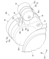
- FIG. FIG. 2 is a perspective view of the meter unit as viewed from the front side of the vehicle.
- ⁇ Entire vehicle> 1 is a left side view of a motorcycle 1, which is an example of a saddle-ride type vehicle.
- the motorcycle 1 of this embodiment includes a front wheel 2, which is a steering wheel, a rear wheel 3, which is a drive wheel, a front fork 4 supporting the front wheel 2, a swing arm 6 supporting the rear wheel 3, a body frame 5 supporting the front fork 4 and the swing arm 6, a rear cushion 7 extending between the swing arm 6 and a seat frame (rear frame) 5a at the rear of the body frame 5, and a power unit 8 supported by the body frame 5.
- the power unit 8 includes, for example, an engine (internal combustion engine, prime mover) and a transmission integrated together.
- a pair of front forks 4 are provided on the left and right.
- the upper parts of the left and right front forks 4 are supported rotatably (steerably) on the head pipe 5b at the front end of the body frame 5 via a steering stem 10.
- the steering stem 10 includes a top bridge 11 and a bottom bridge 12 that connect the upper parts of the left and right front forks 4 together, and also includes a stem pipe (not shown) that is inserted into the head pipe 5b.
- the stem pipe is an axial member that is coaxial with the head pipe 5b.
- a steering handle (bar handle) 15 extending in the vehicle width direction is attached to the top bridge 11.
- reference numeral 16 indicates a fuel tank disposed behind the steering handle 15 and supported by the body frame 5
- reference numeral 17 indicates a seat disposed behind the fuel tank 16 and supported by the seat frame 5a.
- the head pipe 5b has a steering axis (rotation axis, hereafter referred to as the steering axis) C1 that is tilted backward from the vertical direction.
- the wheel side parts including the front wheel 2 and the left and right front forks 4 rotate around the steering axis C1.
- the handle side parts including the steering handle 15 and the handle support members (handle holder 10a and top bridge 11, etc.) rotate around the handle rotation axis (handle rotation axis, hereafter referred to as the handle rotation axis) C2.
- the steering axis C1 and the handle rotation axis C2 are coaxial, and the wheel side parts and the handle side parts rotate integrally.
- the headlight 30 and a pair of left and right front blinkers 31 are supported on the steering stem 10 via light stays (not shown).
- a meter unit 40A is also supported on the top bridge 11.
- the headlight 30, the pair of left and right front blinkers 31, and the meter unit 40A can rotate together with the steering handle 15.
- the meter unit 40A is disposed above the headlight 30 and in front of the top bridge 11. 2, the meter unit 40A of the embodiment is integrally provided with a first meter 40 and a second meter 50, which will be described later.
- the first meter 40 has a first display surface 41 in a circular shape with a relatively large diameter, which is disposed in the center in the vehicle width direction.
- the second meter 50 has a second display surface 51 in a circular shape with a relatively small diameter, which is disposed to the left front of the first display surface 41.
- the first display surface 41 and the second display surface 51 are, for example, planes parallel to each other.
- the meter unit 40A is disposed so that one side of the normal direction of the first display surface 41 and the second display surface 51 faces the head position of the driver (i.e., faces diagonally upward and backward).
- the normal direction of the first display surface 41 and the second display surface 51 is disposed so that it is inclined more inclined (closer to horizontal) than the steering axis direction (direction along the steering axis C1).
- the arrow S1 in FIG. 1 indicates the normal direction (hereinafter, the direction along the arrow S1 is referred to as the normal direction S1).
- the upper side in the normal direction S1 is oriented toward the position of the driver's head.
- Fig. 2 is a top view of the periphery of the top bridge 11 as viewed from the steering axis direction, and will be used as a reference when describing the configuration of the periphery of the meter unit 40A as viewed from the normal direction S1.
- the first display surface 41 is inclined forward and upward from the upper surface of the top bridge 11 in the thickness direction.
- a speedometer (vehicle speed meter, vehicle speed display unit) 44 and various indicator lamps (light-emitting units) 47 are arranged on the first display surface 41.
- the first display surface 41 is the display section of the first meter 40, which includes the speedometer 44 and indicator lamp 47 described above.
- the speedometer 44 of the first meter 40 is, for example, a digital meter (liquid crystal meter) that displays vehicle speed using seven-segment numbers.
- the first meter 40 also has other liquid crystal displays, such as a fuel meter (remaining fuel gauge, remaining fuel display section) 45 and an odometer/trip meter (mileage meter, mileage display section) 46.
- the hollow first meter case 42 contains a first meter body (none shown) that includes a liquid crystal module and its control circuit, as well as a group of indicator lamps and their drive circuits.
- the speedometer 44 may be, for example, an analog meter that indicates vehicle speed with a needle. In that case, a mechanical or electrical needle drive device is contained within the first meter case 42.
- the first meter case 42 has a circular first display surface 41 on its outer surface facing rearward and upward.
- a generally trapezoidal operating unit 48 protrudes from the lower left of the first meter case 42 when viewed from the normal direction S1 of the first display surface 41.
- the operating unit 48 has an operating surface 48a that is generally parallel to the first display surface 41.
- a number of push buttons 48b are arranged on the operating surface 48a for switching the display on the first display surface 41.
- the second display surface 51 is arranged, for example, parallel to the first display surface 41.
- a gear position indicator (gear position display section) 54 that displays the gear (gear position) of the transmission of the power unit 8
- a clock (time display section) 55 that displays the current time are arranged.
- the second display surface 51 is the display section of the second meter 50, which includes a gear position indicator 54 and a clock 55.
- the second meter 50 is a digital meter (liquid crystal meter) similar to, for example, the speedometer 44 of the first meter 40.
- the hollow second meter case 52 houses the second meter body, which includes a liquid crystal module and its control circuit, etc. (neither of which are shown).
- the second meter case 52 has a circular second display surface 51 on its outer surface facing rearward and upward.
- a second operation unit 56 is provided at the bottom end of the second meter case 52.
- the second operation unit 56 has a second push button 56a for switching the display on the second display surface 51.
- a protrusion 11e is provided on the front side of the center of the top bridge 11 in the vehicle width direction.
- the protrusion 11e is plate-shaped forming a protruding upper surface that is approximately parallel to the upper surface of the top bridge 11.
- the protrusion 11e is disposed rearward of the meter unit 40A.
- the protrusion 11e is formed in an approximately trapezoidal shape when viewed from the steering axis direction.
- a through hole is formed in the center of the protrusion 11e in the vehicle width direction, penetrating the protrusion 11e in the steering axis direction.
- the through hole is circular when viewed from the steering axis direction.
- the upper end of the main switch 38 is disposed inside the through hole.
- the main switch 38 is equipped with a key cylinder operated by, for example, a physical key (mechanical key) 38a.
- the key cylinder is arranged with its axis aligned with the steering axis direction, and its circular upper end is arranged inside the through hole.
- a key insertion hole (not shown) opens upward at the upper end of the key cylinder.
- the steering handle 15 comprises a pair of left and right grip portions 15a that are held by the driver, a pair of left and right hanging portions 15b that extend downward from the inner ends of the left and right grip portions 15a in the vehicle width direction, and a straight portion 15c that spans between the lower ends of the left and right hanging portions 15b.
- the straight portion 15c extends horizontally along the vehicle width direction.
- the straight portion 15c is fixed to the upper surface side of the top bridge 11 via a handle holder 10a.
- the meter unit 40A is disposed at a position where the driver looks down in front of the driver when seated on the seat 17 facing the front of the vehicle.
- the meter unit 40A includes a first meter 40 having a speedometer 44 and fixed (permanently installed) to the vehicle body, and a second meter 50 that displays information independent of the first meter 40.
- the second meter 50 is not directly fixed to the vehicle body, but is fixed to the first meter 40 via a connection portion 60, which will be described later.
- the second meter 50 and the connection portion 60 are indicated by hatching.
- the first meter case 42 of the first meter 40 has a first display surface 41 on its outer surface facing upward and rearward. One side (upper and rearward) of the first display surface 41 faces the driver's head position in the normal direction S1.
- the first meter case 42 is configured to include a circular case portion that houses the first meter 40 and a trapezoidal case portion that houses the operating unit 48.
- the first meter case 42 is divided in the normal direction S1 into a first upper case 42a on the first display surface 41 side (passenger side) and a first lower case 42b on the opposite side to the first display surface 41.
- the second meter case 52 of the second meter 50 has a second display surface 51 on its outer surface facing upward and rearward.
- One side (upper and rearward) of the normal direction S1 of the second display surface 51 faces the driver's head position.
- the normal direction of the second display surface 51 and the normal direction of the first display surface 41 are, for example, parallel to each other. In other words, the first display surface 41 and the second display surface 51 are parallel to each other.
- the second meter case 52 is configured to include a second circular case portion that houses the second meter 50.
- the second meter case 52 is divided in the normal direction S1 into a second upper case 52a on the second display surface 51 side (passenger side) and a second lower case 52b on the opposite side to the second display surface 51.
- the first lower case 42b and the second lower case 52b are integrated via a connection portion 60.
- the first lower case 42b, the second lower case 52b, and the connection portion 60 are integrally formed, for example, from the same material.
- the first upper case 42a and the second upper case 52a are formed as separate components that are separate from each other.
- the second meter 50 is set as an optional part, separate from the first meter 40 that is permanently installed on the vehicle body.
- the first lower case 42b forms only the lower part of the second meter case 52, without the second lower case 52b and the connection portion 60 being integrated.
- the first lower case 42b is integrated with the second lower case 52b and the connection portion 60 to form the lower portions of the first meter case 42 and the second meter case 52.
- the part in which the first lower case 42b, the second lower case 52b, and the connection portion 60 are integrated is referred to as the "integrated lower case 52c.”
- the reference numeral 65 indicates a support bracket that supports the meter body and first upper case 42a of the first meter 40 to the top bridge 11.
- the first lower case 42b is fixed by screws or the like to at least one of the meter body and the first upper case 42a supported by the support bracket 65.
- reference numeral 66 denotes a rubber mount portion fastened to the meter body and the first upper case 42a on the support bracket 65
- reference numeral 67 denotes a fastening portion fastened to at least one of the meter body and the first upper case 42a on the first lower case 42b
- reference numeral 68 denotes a connector disposed within the first lower case 42b and connected to the meter body of the first meter 40.
- the first lower case 42b can be attached and detached independently from the meter body and the first upper case 42a supported by the support bracket 65.
- the second meter 50 is not directly supported by the support bracket 65, but is supported by the first lower case 42b via the connection part 60.
- the standard first lower case 42b is replaced with an integrated lower case 52c, and the second lower case 52b is supported by the first lower case 42b.
- the second meter body and the second upper case 52a are attached to this second lower case 52b, forming a meter unit 40A in which the second meter 50 is attached to the first meter 40.
- connection portion 60 extends from the first case toward the second case in a generally trapezoidal shape when viewed from the normal direction S1.
- the second lower case 52b is supported by the first lower case 42b via the connection portion 60.
- the connection portion 60 has, for example, a plate-like wall portion 60a that is substantially parallel to the first display surface 41 and the second display surface 51, and a plurality of rib portions 60b that rise from the wall portion 60a in the normal direction S1.
- the connection portion 60 has, for example, a wiring insertion portion 60c at the middle portion above and below that forms a wiring insertion passage.
- the wiring insertion portion 60c passes through the wiring 49b (see FIG. 5) that extends between the first meter case 42 and the second meter case 52.
- the wiring insertion portion 60c has, for example, a U-shaped cross-sectional shape that opens toward the rear side of the vehicle, which prevents the wiring 49b from being exposed to the front side of the vehicle and allows the wiring 49b to be attached and detached from the rear side of the vehicle.
- the wiring 49b leading to the second meter 50, together with the wiring (not shown) leading to the first meter 40, is connected to the power supply line and various signal lines of the main harness on the vehicle body side.
- the first meter 40 and the second meter 50 are connected to a 12V battery (not shown) that is an on-board power source via the main switch 38 or the like.
- a wiring introduction section (not shown) is provided on the front side of the first meter case 42 for introducing the wiring leading to the first meter 40 and the second meter 50 into the inside of the case.
- the wiring extending from the wiring introduction section to the outside of the case extends downward in front of the steering handle 15 and is connected to the main harness on the vehicle body side.
- the meter unit 40A communicates with a control device or the like of the motorcycle 1, the wiring is also connected to a data communication line on the vehicle body side.
- the thickness (vertical width) H1 of the second meter 50 in the normal direction S1 is approximately the same as the thickness (vertical width) of the operating unit 48 in the normal direction S1, and is smaller than the thickness H1 of the first meter 40 in the normal direction S1.
- the second meter 50 is disposed within the range of the vertical width H1 of the first meter 40.
- the upper surface 52a1 (second display surface 51) of the second meter 50 and the upper surface (operation surface 48a) of the operating unit 48 are displaced downward in the normal direction S1 with respect to the upper surface 42a1 (first display surface 41) of the first meter 40.
- the lower surface 52b1 of the second meter 50 and the lower surface of the operating unit 48 are displaced upward in the normal direction S1 with respect to the lower surface 42b1 of the first meter 40.
- the second meter 50 protruding outward from the outer periphery of the first meter 40 has a smaller diameter (smaller size) than the first meter 40 when viewed from the normal direction S1. Since the second meter 50 is also made smaller in size in the normal direction S1, when the second meter 50 is installed as an optional part, the following effects are achieved. That is, the size and weight of the entire meter unit 40A are suppressed, and the impact on the appearance of the periphery of the meter unit 40A is also suppressed.
- each display portion of the second meter 50 is disposed to the left of the vehicle body left-right center CL and shifted to the left of the left end t2 of the first meter 40 at the vehicle body left-right center CL.
- the gear position display unit 54 which is often viewed while driving, is positioned above the time display unit 55 (as close to the driver as possible) and the character size is made large so that it stands out to the driver.
- symbol C3 indicates the center position (first meter center) of the first display surface 41 of the first meter 40 when viewed from the normal direction S1
- symbol C4 indicates the center position (second meter center) of the second display surface 51 of the second meter 50 when viewed from the normal direction S1.
- the second meter center C4 is located forward of the first meter center C3 in the direction along the display surfaces (surface direction).
- the second meter 50 is located forward of the steering handle 15, which has the following effects. That is, the second meter 50 is less likely to interfere with or overlap the harness, cable, hose, etc. routed around the steering handle 15, and other optional parts supported on the steering handle 15, as viewed from the driver.
- the second meter 50 is located entirely behind the front end t1 of the first meter 40 as viewed from the normal direction S1.
- the outer diameter of the circular shape of the second meter 50 is equal to the radius of the circular shape of the first meter 40. This prevents the second meter 50 from being too conspicuous, suppresses an increase in the weight of the second meter 50, and suppresses an increase in the size of the entire meter unit 40A.
- the motorcycle 1 in the above embodiment includes a first meter 40 having a speedometer 44 and fixed to the vehicle body, and a second meter 50 that displays information independent of the first meter 40 and is fixed to the first meter 40.
- the first meter 40 includes a first meter case 42 having a first display surface 41. One side of the first display surface 41 in its normal direction S1 faces the rider.
- the first meter case 42 is divided into a first upper case 42a on the first display surface 41 side and a first lower case 42b on the opposite side to the first display surface 41 in the normal direction S1.
- the second meter 50 is equipped with a second meter case 52 having a second display surface 51, the second display surface 51 facing the occupant on one side in the normal direction S1, and the second meter case 52 is divided in the normal direction S1 into a second upper case 52a on the second display surface 51 side and a second lower case 52b on the opposite side to the second display surface 51, the first upper case 42a and the second upper case 52a being separate from each other, and the first lower case 42b and the second lower case 52b being integrated with each other via a connection portion 60.
- the vehicle includes a first meter 40 having a speedometer 44 and permanently installed on the vehicle body, and a second meter 50 that is set independently of the first meter 40 as an option setting or the like and is fixed to the first meter 40, and the first upper case 42a of the first meter 40 and the second upper case 52a of the second meter 50 are separate from each other, and the first lower case 42b of the first meter 40 and the second lower case 52b of the second meter 50 are integrated with each other via a connecting portion 60.
- the first meter 40 and the second meter 50 can be integrated using a common lower case (integrated lower case 52c) while the first meter 40 and the second meter 50 have an independent appearance from each other on the display surface side.
- the following effects are obtained. That is, the meter mounting structure can be simplified and the appearance around the meter can be improved.
- the second meter 50 is set as an option, the above-mentioned effects can be obtained by replacing the first lower case 42b with an integrated lower case and providing the second meter 50. Also, when returning to the standard specification without the second meter 50, by returning the integrated lower case to the first lower case 42b, the meter mounting structure does not remain, and quality can be improved.
- a wiring 49b is provided for supplying at least power to the second meter 50, and the wiring 49b extends from a vehicle body side wiring, passes through the first meter case 42, and is arranged in the second meter case 52.
- the wiring 49b leading to the second meter 50 is routed via the first meter case 42, so that the wiring 49b leading to the second meter 50 and the wiring leading to the first meter 40 can be introduced into the first meter case 42 from a common wiring introduction portion. Therefore, compared to a configuration in which the wiring 49b for the second meter 50 is directly introduced into the second meter case 52 without passing through the first meter case 42, the following effects are obtained.
- the wiring can be simplified and the appearance around the meter can be improved.
- the wiring 49b for the second meter 50 into the first meter case 42 fixed to the vehicle body (i.e., close to the vehicle body)
- the following effects are obtained compared to a configuration in which the wiring 49b for the second meter 50 is directly introduced into the second meter case 52. That is, the exposure of the wiring 49b for the second meter 50 is suppressed, and the wiring 49b can be easily protected and the appearance can be improved.
- connection portion 60 between the first lower case 42b and the second lower case 52b has a wire insertion portion 60c that covers the portion of the wire 49b that passes through the connection portion 60.
- this configuration by providing a wiring insertion portion 60c at the connection portion 60 between the first lower case 42b and the second lower case 52b, exposure of the wiring 49b between the first lower case 42b and the second lower case 52b is reduced, making it easier to protect the wiring 49b and improving the appearance.
- the second meter 50 has a gear position display unit 54 that displays the gear position of the saddle-ride type vehicle, and the second meter 50 is located to the left of the first meter 40 when viewed from the passenger side on one side of the normal direction S1.
- the second meter 50 having the gear position display portion is positioned to the left of the first meter 40 when viewed from the occupant's side.
- the second meter 50 has a time display unit 55 that displays the current time, and the second meter 50 is located to the left of the first meter 40 when viewed from the passenger side on one side of the normal direction S1.
- the second meter 50 having the time display unit 55 is positioned on the left side as seen from the occupant's side, which, combined with the fact that wristwatches are generally worn on the left arm, makes it easier for the occupant to intuitively recognize that the display on the second meter 50 on the left side is a time display.
- the second meter 50 has a gear position display unit 54 that displays the gear position of the motorcycle 1 and a time display unit 55 that displays the current time, and the gear position display unit 54 is located above the time display unit 55 when viewed from the rider's side on one side of the normal direction S1. According to this configuration, the gear position display unit 54 is disposed above the time display unit 55, so that the display of the gear position can be emphasized.
- the second meter 50 has a gear position display unit 54 that displays the gear position of the motorcycle 1 and a time display unit 55 that displays the current time, and the gear position display unit 54 displays in a larger character size than the time display unit 55. According to this configuration, by making the character size of the gear position display section 54 larger than that of the time display section 55, the display of the gear position can be emphasized.
- the second meter 50 has a vertical width H2 in the normal direction S1 which is narrower than the vertical width H1 of the first meter 40 in the normal direction S1, and the second meter 50 is disposed within the vertical width H1 of the first meter 40 in the normal direction S1.
- the vertical width H2 of the second meter 50 is narrower than the vertical width H1 of the first meter 40, and the second meter 50 is disposed within the vertical width H1 of the first meter 40 in the normal direction S1, which has the following effects: That is, even in a state in which the second meter 50 is mounted on the first meter 40, the second meter 50 can be disposed as compactly as possible, and an increase in size around the meter can be avoided.
- the first meter 40 and the second meter 50 are located in front of the steering handlebar 15, and the first meter 40 and the second meter 50 respectively have a first display surface 41 and a second display surface 51 which are circular when viewed from the normal direction S1, and the center C4 of the circle of the second display surface 51 is located forward of the center C3 of the circle of the first display surface 41 in the direction along the first display surface 41.
- the first meter 40 and the second meter 50 are positioned in front of the steering wheel 15, and the second meter 50 is positioned further forward than the first meter 40 in the direction along the surface of the first display surface 41, so that the second meter 50 is located further forward from the steering wheel 15. This makes it possible to prevent the second meter 50 from interfering with harnesses, cables, hoses, etc. arranged around the steering wheel 15.
- the present invention is not limited to the above-described embodiment.
- the meter structure of the present embodiment may be applied to a saddle-ride type vehicle other than a motorcycle.
- the saddle-ride type vehicle includes all vehicles on which a driver straddles the vehicle body, including not only motorcycles (including motorized bicycles and scooter-type vehicles), but also three-wheeled vehicles (including vehicles with one front wheel and two rear wheels, as well as vehicles with two front wheels and one rear wheel) or four-wheeled vehicles (such as four-wheeled buggies).
- the present invention may be applied to vehicles that include an electric motor as a prime mover.
- the present invention may be applied to vehicles other than saddle-ride type vehicles (passenger cars, buses, trucks, etc.).
- the configurations in the above-described embodiments are merely examples of the present invention, and various modifications are possible without departing from the gist of the present invention, such as replacing the components of the embodiments with well-known components.
Landscapes
- Engineering & Computer Science (AREA)
- Mechanical Engineering (AREA)
- Instrument Panels (AREA)
Priority Applications (1)
| Application Number | Priority Date | Filing Date | Title |
|---|---|---|---|
| JP2024566170A JP7814555B2 (ja) | 2022-12-22 | 2023-12-22 | 鞍乗り型車両のメータ構造 |
Applications Claiming Priority (2)
| Application Number | Priority Date | Filing Date | Title |
|---|---|---|---|
| JP2022205738 | 2022-12-22 | ||
| JP2022-205738 | 2022-12-22 |
Publications (1)
| Publication Number | Publication Date |
|---|---|
| WO2024135830A1 true WO2024135830A1 (ja) | 2024-06-27 |
Family
ID=91589008
Family Applications (1)
| Application Number | Title | Priority Date | Filing Date |
|---|---|---|---|
| PCT/JP2023/046173 Ceased WO2024135830A1 (ja) | 2022-12-22 | 2023-12-22 | 鞍乗り型車両のメータ構造 |
Country Status (2)
| Country | Link |
|---|---|
| JP (1) | JP7814555B2 (https=) |
| WO (1) | WO2024135830A1 (https=) |
Citations (8)
| Publication number | Priority date | Publication date | Assignee | Title |
|---|---|---|---|---|
| JPS58118465A (ja) * | 1982-01-07 | 1983-07-14 | ヤマハ発動機株式会社 | 小物容器を有する自動二輪車 |
| JPH0437091U (https=) * | 1990-07-26 | 1992-03-27 | ||
| JP2009090883A (ja) * | 2007-10-10 | 2009-04-30 | Yamaha Motor Co Ltd | 鞍乗型車両 |
| JP2010143331A (ja) * | 2008-12-17 | 2010-07-01 | Honda Motor Co Ltd | 車両用メータ装置 |
| JP2018095139A (ja) * | 2016-12-15 | 2018-06-21 | 川崎重工業株式会社 | 自動二輪車の通信機器アンテナ配置構造 |
| WO2019064699A1 (ja) * | 2017-09-28 | 2019-04-04 | 本田技研工業株式会社 | 鞍乗型車両のメータ支持構造 |
| JP2020185845A (ja) * | 2019-05-13 | 2020-11-19 | 日本精機株式会社 | 計器装置 |
| CN215622447U (zh) * | 2021-07-27 | 2022-01-25 | 姚攀 | 一种全贴合式摩托车仪表 |
-
2023
- 2023-12-22 WO PCT/JP2023/046173 patent/WO2024135830A1/ja not_active Ceased
- 2023-12-22 JP JP2024566170A patent/JP7814555B2/ja active Active
Patent Citations (8)
| Publication number | Priority date | Publication date | Assignee | Title |
|---|---|---|---|---|
| JPS58118465A (ja) * | 1982-01-07 | 1983-07-14 | ヤマハ発動機株式会社 | 小物容器を有する自動二輪車 |
| JPH0437091U (https=) * | 1990-07-26 | 1992-03-27 | ||
| JP2009090883A (ja) * | 2007-10-10 | 2009-04-30 | Yamaha Motor Co Ltd | 鞍乗型車両 |
| JP2010143331A (ja) * | 2008-12-17 | 2010-07-01 | Honda Motor Co Ltd | 車両用メータ装置 |
| JP2018095139A (ja) * | 2016-12-15 | 2018-06-21 | 川崎重工業株式会社 | 自動二輪車の通信機器アンテナ配置構造 |
| WO2019064699A1 (ja) * | 2017-09-28 | 2019-04-04 | 本田技研工業株式会社 | 鞍乗型車両のメータ支持構造 |
| JP2020185845A (ja) * | 2019-05-13 | 2020-11-19 | 日本精機株式会社 | 計器装置 |
| CN215622447U (zh) * | 2021-07-27 | 2022-01-25 | 姚攀 | 一种全贴合式摩托车仪表 |
Also Published As
| Publication number | Publication date |
|---|---|
| JPWO2024135830A1 (https=) | 2024-06-27 |
| JP7814555B2 (ja) | 2026-02-16 |
Similar Documents
| Publication | Publication Date | Title |
|---|---|---|
| JP5955503B2 (ja) | 車両のハンドル支持構造 | |
| US11279435B2 (en) | Operation unit structure of straddle-type vehicle, and straddle-type vehicle | |
| CN102811900B (zh) | 车辆的显示装置 | |
| EP2868557B1 (en) | Saddle type vehicle | |
| JP4827130B2 (ja) | 車両用メータパネル装置 | |
| JP7814555B2 (ja) | 鞍乗り型車両のメータ構造 | |
| CN101612972B (zh) | 摩托车 | |
| CN101544253A (zh) | 机动二轮车用车速仪表 | |
| EP3960515B1 (en) | Straddled vehicle | |
| JP6119161B2 (ja) | 自動二輪車 | |
| CN110461693B (zh) | 鞍乘型车辆的前灯支承结构 | |
| CN103129649B (zh) | 跨骑式车辆的车灯组件 | |
| EP4101749B1 (en) | Straddled vehicle | |
| CN102001388A (zh) | 机动二轮车 | |
| JP7366973B2 (ja) | 鞍乗型車両 | |
| JP2020179722A (ja) | 鞍乗車両 | |
| JP2020045054A (ja) | 鞍乗型車両のフロント構造 | |
| JP4476763B2 (ja) | 電気式メータ装置 | |
| JP6345723B2 (ja) | 車両のメータ装置 | |
| JP2020045055A (ja) | 車体カバーおよび鞍乗型車両 | |
| JP5775914B2 (ja) | 鞍乗り型車両における電装部品のケーブル配索構造 | |
| JP7369749B2 (ja) | 鞍乗型車両 | |
| JP7585626B2 (ja) | 鞍乗型車両のフロント構造 | |
| CN100532185C (zh) | 两轮车的显示装置 | |
| JP2025146272A (ja) | 鞍乗り型車両 |
Legal Events
| Date | Code | Title | Description |
|---|---|---|---|
| 121 | Ep: the epo has been informed by wipo that ep was designated in this application |
Ref document number: 23907190 Country of ref document: EP Kind code of ref document: A1 |
|
| DPE1 | Request for preliminary examination filed after expiration of 19th month from priority date (pct application filed from 20040101) | ||
| WWE | Wipo information: entry into national phase |
Ref document number: 2024566170 Country of ref document: JP |
|
| WWE | Wipo information: entry into national phase |
Ref document number: 202547066962 Country of ref document: IN |
|
| NENP | Non-entry into the national phase |
Ref country code: DE |
|
| WWP | Wipo information: published in national office |
Ref document number: 202547066962 Country of ref document: IN |
|
| 122 | Ep: pct application non-entry in european phase |
Ref document number: 23907190 Country of ref document: EP Kind code of ref document: A1 |